

Hayward HP50A, HP85A Installation Instructions Manual

SWIMMING POOL HEAT PUMP UNIT
Installation&Instruction Manual
Model HP50A
Hayward Pool Products Canada, Inc.
T: 1-888-238-7665
www.haywardpool.ca
3149010
HP85A

CONTENTS
1. Preface 1
2. Specifications 2
2.1 Performance Data of Swimming Pool Heat Pump Unit 2
2.2 Dimensions for Swimming Pool Heat Pump Unit 3
3. Installation and Connection 4
3.1 Installation of System 4
3.2 Swimming Pool Heat Pumps: Location 5
3.3 How Close to Your Pool? 5
3.4 Swimming Pool Heat Pumps: Plumbing 6
3.5 Swimming Pool Heat Pumps: Electrical Connection 7
3.6 Initial Start-up of the Unit 7
4. Usage and operation 8
4.1 The Functions of the LCD Controller 8
4.2 How to Set Operation Parameters 8
4.3 Usage of the controller 10
5. Maintenance and inspection 11
5.1 Maintenance 11
5.2 Trouble Shooting Guide 11
6. Appendix 12
6.1 Connection of PCB: Illustration 12
6.2 Wiring Diagram 13
6.3 Exploded View and Spare Parts 15
6.4 Parts List and Spare Parts
6.5 Warranty
18
19

1
1. PREFACE
In order to provide our customers with quality, reliability and versatility, this
product has been made to strict production standards. This manual includes
all the necessary information about installation, debugging, discharging and
maintenance. Please read this manual carefully before you open or maintain
the unit. The manufacturer of this product will not be held responsible if
someone is injured or the unit is damaged as a result of improper installation,
debugging, or unnecessary maintenance. It is vital that the instructions within
this manual are adhered to at all times. The unit must be installed by qualified
personnel.
• The unit can only be repaired by qualified installer centre personnel or an
authorised dealer (HVAC).
• Maintenance and operation must be carried out according to the recommended
time and frequency, as stated in this manual.
• Use genuine standard spare parts only.
• Failure to comply with these recommendations will invalidate the warranty.
• The Swimming Pool Heat Pump Unit heats the swimming pool water and keeps the
temperature constant.
This type of pump has the following characteristics:
1. Durable
The heat exchanger is made of PVC & titanium; the tube can withstand prolonged
exposure to corrosives such as chlorine.
2. Quiet operation
The unit comprises an efficient rotary compressor and a low noise fan motor, which
guarantees its quiet operation.
3. Electronic control board
The unit is controlled by a micro-controller, allowing all operation parameters to be
set. Operation status can be displayed on the control panel.

2
2.
SPECIFICATIONS
2.1
Performance data of Swimming Pool Heat Pump Unit
***
REFRIGERANT: R410A
Unit
HP50A
Heating Capacity
kW
BTU/h
14.7
50,000
Heating Power Input kW 2.6
Running Current A 11.8
Compressor Rating Load A 11.3
Compressor Locked Rotor Load
A 60
Minimum Circuit Ampactiy
A 20
Max.Fuse A 30
Power Supply V/Ph/Hz
Compressor Quantity 1
Compressor(s) Rotary
Fan Quantity
1
Fan Power Input W
120
Fan Rotate Speed RPM 850
Fan Direction horizontal
Noise (at 1 meter) dB(A) 54
Water Connection inch 1.5
Water Flow Volume Imperial/US GPM 20
Water Pressure Drop(max) PSI 1.5
Unit Net Dimensions(L/W/H) inch 40.8/16.4/25.6
Unit Shipping Dimensions(L/W/H) inch 44.5/18.5/27.2
Net Weight/Shipping Weight lb. 143/154
1
Model
HP85A
24.9
85,000
4.9
23.3
22.3
139
34
55
1
Scroll
2
120
850
horizontal
58
1.5
33
1.74
41.2/17.9/49.2
44.5/18.5/51.2
276/298
1
208-230V /60Hz208-230V /60Hz
~
~
3
2.
SPECIFICATIONS
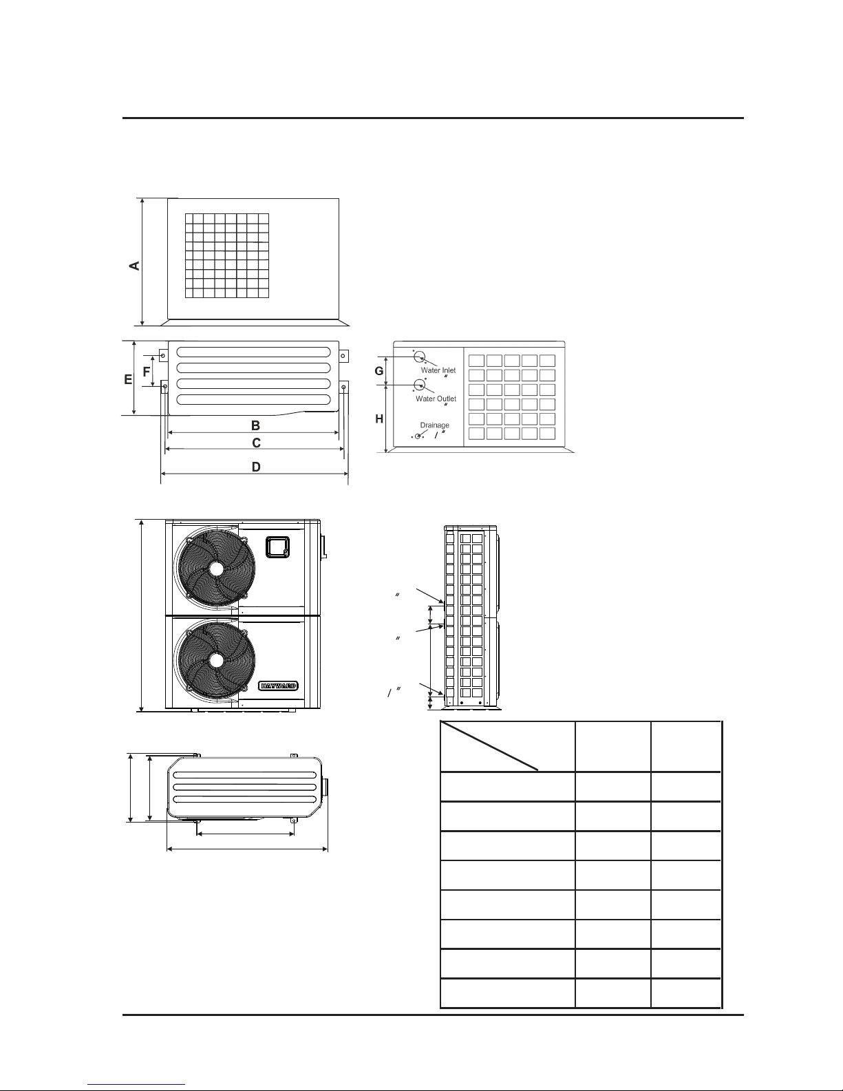
2.2
Dimensions for the Swimming Pool Heat Pump Unit
Model:HP50A
HP50A
A 650/25.6
B 1000/39.4
C 1015/40.0
D 1035/40.8
E 415/16.3
F 220/8.7
G 150/5.9
H 338/13.3
SIZE
TYPE
Unit : mm / inch
Water Inlet
Drainage
G
H
F
Water Outlet
C
E
B
A
D
HP85A
1045/41.2
455/17.9
1250/49.2
630/24.8
430/17.0
120/4.8
500/19.7
82/3.3
Model:HP85A
1.5
1.5
3 4
1.5
1.5
1 2
4
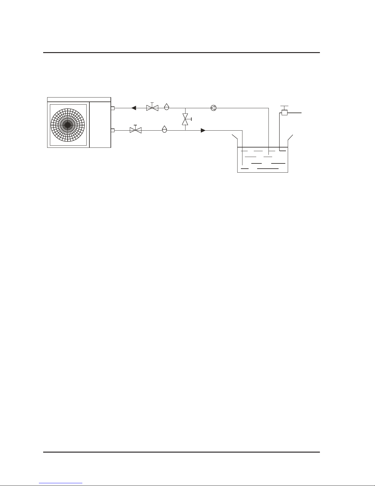
3. INSTALLATION AND CONNECTION
3.1 Installation illustration
Installation items:
The factory only provides the heat pump unit; the other items in the illustration are
necessary spare parts for the water system, provided by users or the installer.
Attention:
Please follow these steps when using for the first time
1. Open valve and charge water
2. Make sure that the pump and the water-in pipe have been filled with water
3. Close the valve and start the unit
ATTN: It is necessary that the water-in pipe inlet be higher than the pool surface.
Chlorinator cell
Water outlet
Pool
Valve
Water supply
Water inlet
Water pump
Sand filter
(or other type filter)
By-pass valve
Installation must be performed in accordance with the requirements of NEC and CEC
by authorized personnel only.
(optional)

5
3. INSTALLATION AND CONNECTION
3.2 Swimming Pool Heat Pumps: Location
The unit will perform well in any outdoor location provided that the following three
factors are present:
1. Fresh Air - 2. Electricity - 3. Pool filter piping
The unit may be installed virtually anywhere outdoors. For indoor pools consult the
supplier. Unlike a gas heater, it has no draft or pilot light problem in a windy area.
DO NOT place the unit in an enclosed area with a limited air volume, where the units
discharge air will be re-circulated.
DO NOT place the unit next to shrubs which can block the air inlet. These locations
deny the unit a continuous source of fresh air which reduces its efficiency and may
prevent adequate heat delivery.
3.3 How Close To Your Pool?
Normally, the pool heat pump is installed within 7.5 metres of the pool. The
longer the distance from the pool, the greater the heat loss from the piping.
For the most part, the piping is buried. Therefore, the heat loss is minimal for
runs of up to15 metres (15 metres to and from the pump = 30 metres total),
unless the ground is wet or the water table is high. A very rough estimate of
heat loss per 30 metres is 0.6 Kw-hour (2000BTU) for every 5°C difference in
temperature between the pool water and the ground surrounding the pipe,
which translates to 3% to 5% increase in operating time for the water to reach
the desired temperature.
Air inlet
Air outlet
2500mm
700mm
300mm
700mm
500mm
 Loading...