

Page 1
NOTIC
abe
ca
tes specia
uctions that are
but not related to hazards.
Models HP6003T, HP11003T, HP2100TCO3T,
HP13023772 Rev: B
OWNERS OPERATION & PARTS MANUAL
Attention
Installer:
Give this manual to
the homeowner.
Important Information to
keep for Service
Model # ___________________
Serial # ____________________
Install Date ________________
HP21003T, HP21203T
SAVE THIS OWNERS MANUAL
The Hayward HeatPro Heat Pump is listed by ETL as complying with the latest edition of the “UL Standard for Safety for
Heating and Cooling Equipment”, UL1995 and CSA C22.2 No. 236.
All Hayward HeatPro Heat Pumps must be installed in accordance with all applicable National and Local codes. In the absence
of local codes, refer to the latest edition of the National Electric Code (NEC) in the United States and the Canadian Electric
Code (CEC) in Canada
Basic safety precautions should always be followed, including the following: Failure to follow instructions can cause severe
injury and/or death.
This is the safety-alert symbol. When you see this symbol on your equipment or in this manual, look for one of the
following signal words and be alert to the potential for personal injury.
WARNING warns about hazards that could cause serious personal injury, death or major property damage and if
ignored presents a potential hazard.
CAUTION warns about hazards that will or can cause minor or moderate personal injury and/or property damage
and if ignored presents a potential hazard. It can also make consumers aware of actions that are unpredictable and unsafe.
The
E l
l indi
l instr
important
USE ONLY HAYWARD GENUINE REPLACEMENT PARTS
Pomona, CA Clemmons, NC Nashville, TN
Tel: 908.351.5400 www.haywardpool.com
Page 2
Page 2 of 24 HEATPRO HEAT PUMP HP13023772 Rev: B
IMPORTANT SAFETY INSTRUCTIONS
READ AND FOLLOW ALL INSTRUCTIONS IN THIS OWNER’S
MANUAL AND ON EQUIPMENT.
Before servicing this electrical equipment, turn power supply OFF.
KEEP ALL LABELS IN GOOD CONDITION AND REPLACE IF MISSING OR DAMAGED.
WARNING – To reduce risk of injury, do not permit children to use or climb on the heat pump, pumps or filters. Closely supervise
children at all times. Components such as the filtration system, pumps, and heaters must be positioned to prevent children from using them as a
means of access to the pool.
CAUTION – This heat pump is intended for use on permanently installed swimming pools and may also be used with spas. Do NOT use
with storable pools. A permanently installed pool is constructed in or on the ground or in a building such that it cannot be readily disassembled for
storage. A storable pool is constructed so that it is capable of being readily disassembled for storage and reassembled to its original integrity.
Though this product is designed for outdoor use, it is strongly recommended to protect the electrical components from the weather. Select a welldrained area, one that will not flood when it rains. It requires free circulation of air for cooling. Do not install in a damp or non-ventilated location.
WARNING – Risk of Electric Shock. All electrical wiring MUST be in conformance with all applicable local
codes, regulations and the National Electric Code (NEC). Hazardous voltage can shock, burn, and cause death or serious
property damage. Provide a properly located outlet. All electrical wiring MUST be in conformance with applicable local
and national codes and regulations. Before working on this unit, turn off power supply to the heat pump.
WARNING – To reduce the risk of electric shock replace damaged wiring immediately. Locate conduit to
prevent abuse from lawn mowers, hedge trimmers and other equipment.
WARNING – Failure to bond heat pump to pool structure will increase risk for electrocution and could result in injury or death. To reduce
the risk of electric shock, the electrician must comply with installation instructions and must bond the heat pump accordingly. In addition, the
licensed electrician must also conform to local electrical codes for bonding requirements.
Notes to the electrician:
Use a solid copper conductor, size 8 or larger. Run a continuous wire from external bonding lug to reinforcing rod or mesh. Connect a No. 8 AWG
(8.4 mm
electrical equipment, metal piping (except gas piping), and conduit within 5 ft. (1.5 m) of inside walls of swimming pool or spa. IMPORTANT -
Reference NEC codes for all wiring standards including, but not limited to, grounding, bonding and other general wiring procedures.
2
) solid copper bonding wire to the grounding lug provided on the heat pump and to all metal parts of swimming pool or spa, and to all
WARNING – Suction Entrapment Hazard.
Suction in suction outlets and/or suction outlet covers which are damaged, broken, cracked, missing, or unsecured can cause
severe injury and/or death due to the following entrapment hazards:
Hair Entrapment- Hair can become entangled in suction outlets.
Limb Entrapment- A limb inserted into an opening of a suction outlet or suction outlet cover that is damaged, broken,
cracked, missing, or not securely attached can result in a mechanical bind or swelling of the limb.
Body Suction Entrapment- A differential pressure applied to a large portion of the body or limbs can result in an entrapment.
Evisceration/ Disembowelment - A vacuum applied directly to the intestines through an unprotected suction outlet sump or
suction outlet cover which is damaged, broken, cracked, missing, or unsecured can result in evisceration (disembowelment).
Mechanical Entrapment- There is potential for jewelry, swimsuit, hair decorations, finger, toe or knuckle to be caught in an
opening of a suction outlet or suction outlet cover resulting in mechanical entrapment.
WARNING - To reduce the risk of entrapment hazards:
o When suction outlets are less than a 18” x 23” [45cm x 58cm] equivalent, a minimum of two functioning suction
outlets per pump must be installed. Suction outlets in the same plane (i.e. floor or wall), must be installed a
minimum of three feet (3’) [1 m] apart, as measured from near point to near point.
o Dual suction outlets shall be placed in such locations and distances to avoid “dual blockage” by a user.
USE ONLY HAYWARD GENUINE REPLACEMENT PARTS
Pomona, CA Clemmons, NC Nashville, TN
Tel: 908.351.5400 www.haywardpool.com
Page 3
Page 3 of 24 HEATPRO HEAT PUMP HP13023772 Rev: B
o Dual suction fittings shall not be located on seating areas or on the backrest for such seating areas.
o The maximum system flow rate shall not exceed the flow rating of any listed (per current revision of ASME/ANSI A112.19.8) suction
outlet cover installed.
o Never use the Pool or Spa if any suction outlet component is damaged, broken, cracked, missing, or not securely attached.
o Replace damaged, broken, cracked, missing, or not securely attached suction outlet components immediately.
o In addition two or more suction outlets per pump installed in accordance with latest APSP (formally NSPI) Standards and CPSC
guidelines, follow all National, State, and Local codes applicable.
WARNING – Never operate or test the circulation system at more than 50 PSI.
WARNING – Failure to remove pressure test plugs and/or plugs used in winterization of the pool/spa from the suction outlets can
result in an increase potential for suction entrapment as described above.
WARNING – Failure to keep suction outlet components clear of debris, such as leaves, dirt, hair, paper and other materials can
result in an increase potential for suction entrapment as described above.
WARNING – Suction outlet components have a finite life, the cover/grate should be inspected frequently and replaced at least every
ten years or if found to be damaged, broken, cracked, missing, or not securely attached.
WARNING – All suction and discharge valves MUST be OPEN when starting the circulation system. Failure to do so could result in
severe personal injury and/or property damage. All drains and suction outlets MUST have properly installed covers, securely attached using the
screws supplied with the covers. If screws are lost, order replacement parts from your supplier.
WARNING – Hazardous Pressure. Pool and spa water circulation systems operate under hazardous pressure during
start up, normal operation, and after pump shut off. Stand clear of circulation system equipment during start up. Failure to
follow safety and operation instructions could result in violent separation of the pump housing and cover due to pressure in the
system, which could cause property damage, severe personal injury, or death. Before servicing pool and spa water circulation
system, all system and pump controls must be in off position and filter manual air relief valve must be in open position. Before
starting system pump, all system valves must be set in a position to allow system water to return back to the pool. Do not change
filter control valve position while system pump is running. Before starting system pump, fully open filter manual air relief valve.
Do not close filter manual air relief valve until a steady stream of water (not air or air and water) is discharged.
WARNING – Separation Hazard. Failure to follow safety and operation instructions could result in violent
separation of pump components. Strainer cover must be properly secured to pump housing with strainer cover lock ring. Before
servicing pool and spa circulation system, filter manual air relief valve must be in open position. Do not operate pool and spa
circulation system if a system component is not assembled properly, damaged, or missing. Do not operate pool and spa
circulation system unless filter air relief valve body is in locked position in filter upper body.
WARNING – Fire and burn hazard. Motors operate at high temperatures and if they are not properly isolated from any flammable
structures or foreign debris they can cause fires, which may cause severe personal injury or death. It is also necessary to allow the motor to cool for
at least 20 minutes prior to maintenance to minimize the risk of burns.
WARNING – Failure to install according to defined instructions may result in severe personal injury or death.
WARNING – The following “Safety Rules for Hot Tubs” recommended by the U.S. Consumer Product Safety Commission should be
observed when using the spa.
1. Spa or hot tub water temperatures should never exceed 104°F [40°C]. A temperature of 100°F [38°C] is considered safe for a healthy adult.
Special caution is suggested for young children. Prolonged immersion in hot water can induce hyperthermia.
2. Drinking of alcoholic beverages before or during spa or hot tub use can cause drowsiness, which could lead to unconsciousness and
subsequently result in drowning.
3. Pregnant women beware! Soaking in water above 100°F. [38°C] can cause fetal damage during the first three months of pregnancy (resulting
in the birth of a brain-damaged or deformed child). Pregnant women should adhere to the 100°F. [38°C] maximum rule.
4. Before entering the spa or hot tub, users should check the water temperature with an accurate thermometer; spa or hot tub thermostats may err in
regulating water temperatures by as much as 4°F (2.2°C).
5. Persons taking medications, which induce drowsiness, such as tranquilizers, antihistamines or anticoagulants, should not use spas or hot tubs.
USE ONLY HAYWARD GENUINE REPLACEMENT PARTS
Pomona, CA Clemmons, NC Nashville, TN
Tel: 908.351.5400 www.haywardpool.com
Page 4

Page 4 of 24 HEATPRO HEAT PUMP HP13023772 Rev: B
6. If the pool/spa is used for therapy, it should be done with the advice of a physician. Always stir pool/spa water before entering the pool/spa to
mix in any hot surface layer of water that might exceed healthful temperature limits and cause injury. Do not tamper with controls, because
scalding can result if safety controls are not in proper working order.
7. Persons with a medical history of heart disease, circulatory problems, diabetes or blood pressure problems should obtain a physicians advice
before using spas or hot tubs.
8. Hyperthermia occurs when the internal temperature of the body reaches a level several degrees above normal body temperature of 98.6°F.
[37°C]. The symptoms of Hyperthermia include: drowsiness, lethargy, dizziness, fainting, and an increase in the internal temperature of the
body.
The effects of Hyperthermia include:
1. Unawareness of impending danger.
2. Failure to perceive heat.
3. Failure to recognize the need to leave the spa.
4. Physical inability to exit the spa.
5. Fetal damage in pregnant women.
6. Unconsciousness resulting in danger of drowning.
DEFINITIONS:
Suction Outlet – The term Suction Outlet is a fitting, fitting assembly, cover/grate and related components that provide a means for water to exit the
pool and into the pump circulating system.
Inches of Mercury (in Hg) - A unit for measuring pressure below atmospheric (“suction” or “vacuum”) (1.0 inch Hg = .491 PSI)
Main Drain – See Suction Outlet
PSI – An abbreviation for pounds per square inch.
General Information:
Swimming Pool Energy Saving Tips
It is important to note that a heat pump will not heat a pool as fast as a gas heater. If the pool water is allowed to
cool significantly, it may take a heat pump several days to return pool water to the desired temperature. For
weekend use, it is more economical to maintain the pool water temperature at the desired temperature. If pool
use is not planned for a prolonged period, energy consumption can be minimized by either turning off the heat
pump or by decreasing the temperature setting several degrees.
Hayward Pool Products offers the following recommendations to help conserve energy and minimize the cost of
operating the heat pump.
1. Carefully monitor the water temperature of the pool in the summertime.
2. During the winter or when on vacation longer than a week, turn off the heat pump and follow the
winterization procedures in this manual.
3. Where possible, shelter the pool from prevailing winds with well-trimmed hedges or other landscaping,
cabanas, or fencing.
4. The use of a pool cover is recommended. A pool cover will provide a valuable safety feature, reduce heat
loss, conserve chemicals, and reduce the load on filter systems.
USE ONLY HAYWARD GENUINE REPLACEMENT PARTS
Pomona, CA Clemmons, NC Nashville, TN
Tel: 908.351.5400 www.haywardpool.com
Page 5
Page 5 of 24 HEATPRO HEAT PUMP HP13023772 Rev: B
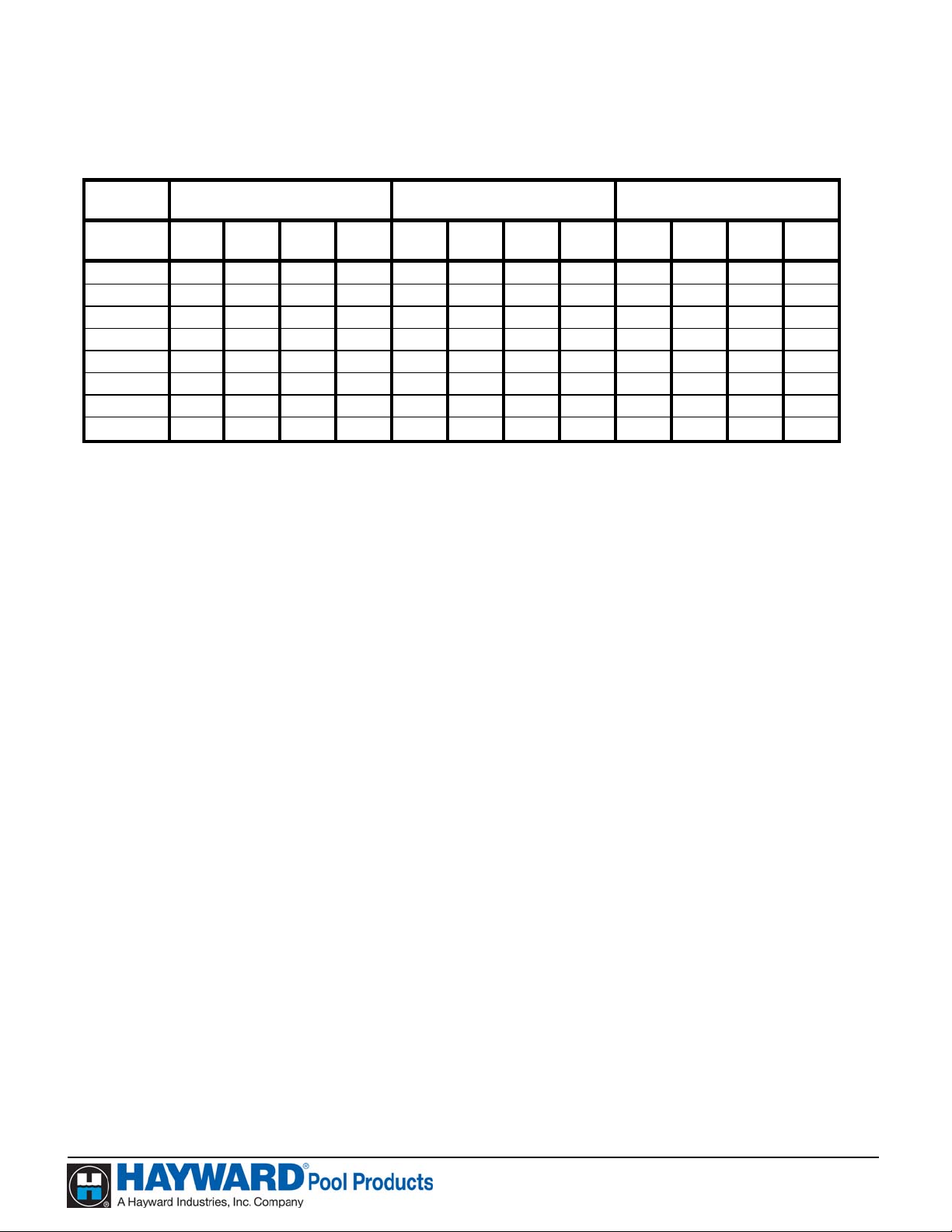
The following table lists the minutes it will take to heat a pool 1°F, based on gallons. This is an approximation
only.
HP21003T, HP2100TCO3T,
HP11003T
HP6003T
Pool Size in
Model HP21203T
Gallons
200 1 1 2 2 1 1 2 2 2 2 2 2
500 2.5 2.5 2.5 3 3 3 3 4 4 5 5 6
1000 4 5 5 6 5 6 6 7 8 10 11 12
1500 7 8 8 9 8 9 9 11 13 14 16 18
2000 8 10 10 12 10 12 12 14 17 19 21 24
5000 21 24 26 29 25 29 31 35
10000 42 48 52 59 50 58 62 71
20000 83 97 104 118 100 116 125 141
80°F 70°F 60°F 50°F 80°F 70°F 60°F 50°F 80°F 70°F 60°F 50°F
Features:
- UV resistant cabinet;
Scroll compressor for quiet operation;
-
Energy efficient heating of your pool and spa;
-
Digital Electronic Control (All Models):
-
o Easy to read display;
o Continuous digital temperature display;
o Dual thermostats for independent temperature control of pool and spa
(Single thermostat for model HP11002 only);
o Display of self diagnostic codes to monitor heat pump performance;
o Control Lock Out Function;
o Defrost Function to prevent evaporator coil freeze up;
Titanium Heat Exchanger withstands the harshest conditions.
-
USE ONLY HAYWARD GENUINE REPLACEMENT PARTS
Pomona, CA Clemmons, NC Nashville, TN
Tel: 908.351.5400 www.haywardpool.com
Page 6
Page 6 of 24 HEATPRO HEAT PUMP HP13023772 Rev: B
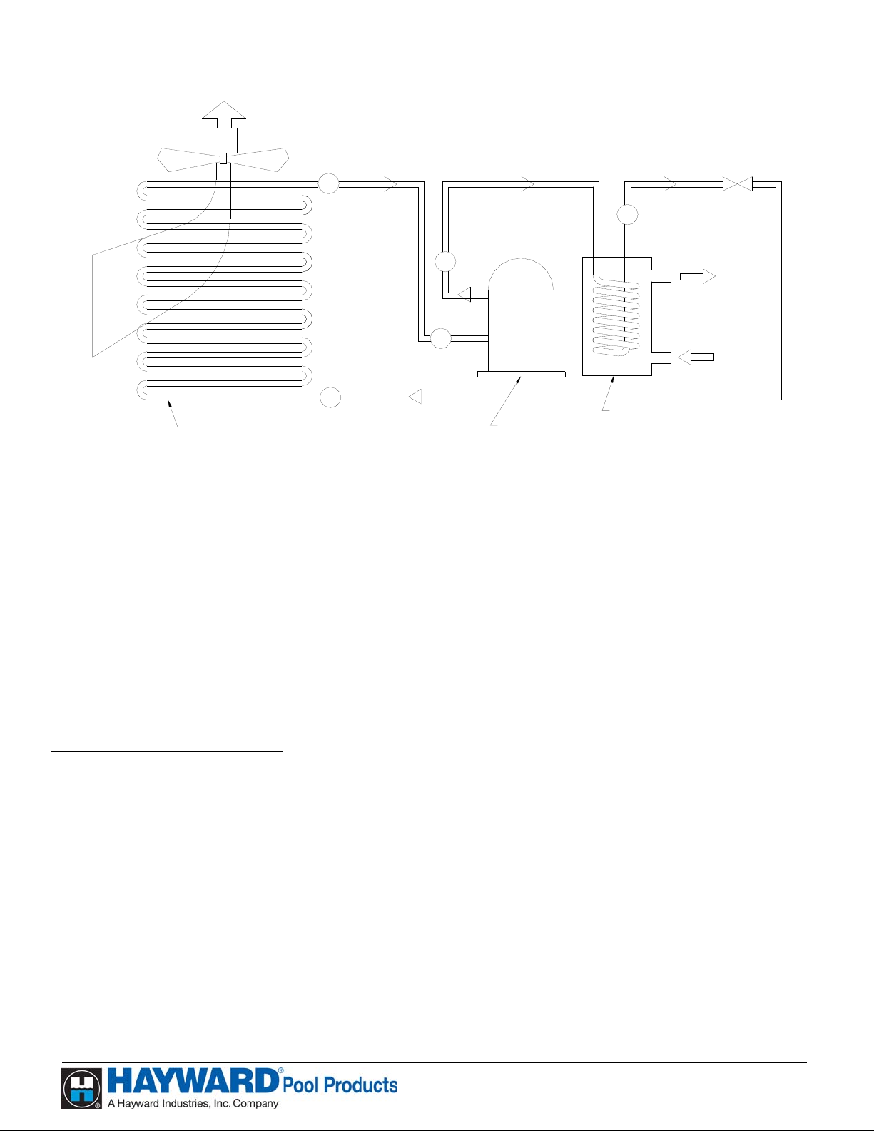
How a Heat Pump Works
C
A
TXV
HEAT
FROM
AIR
B
AIR COIL (EVAPORATOR)
E
D
WATER HEAT EXCHANGER
COMPRESSOR
(CONDENSER)
HOT
WATER
OUT
COLD
WATER
IN
The heat pump takes heat from the environment and uses it to heat the pool water. During heat pump operation,
high temperature, high-pressure sub cooled liquid Refrigerant (A) is throttled by Metering Device (TXV) and
turned into low temperature, low-pressure saturated liquid (B). The two-phase Refrigerant flows through the Air
Coil (Evaporator), where the liquid refrigerant evaporates into vapor by absorbing heat from the surrounding
air. At the outlet of the Air Coil (Evaporator) it becomes a low temperature, low-pressure superheated vapor
(C). The Compressor receives this flow at the suction line (D), and compresses it into a high temperature, high
pressure superheated vapor, which is discharged from the Compressor (E) and flows into the Water Heat
Exchanger (Condenser). The heat carried by the flow is then released to the surrounding water from the pool. At
the same time, the high temperature, high-pressure superheated vapor is then condensed back to high-pressure
sub cooled liquid (A), which completes the cycle. The water, which is being forced through the Water Heat
Exchanger (Condenser) by the pool pump, is heated as it passes through.
Becoming Familiar with Your Heat Pump
Heat Pump Protection Features
Hayward heat pumps are equipped with safeguards that will stop operation to protect the unit in case of the
following events:
• Excessively high refrigerant pressure
• Excessively high water temperature
• Loss of refrigerant
• Fan Motor Failure
• Evaporator Freeze-up
• Low Ambient Temperature
USE ONLY HAYWARD GENUINE REPLACEMENT PARTS
Pomona, CA Clemmons, NC Nashville, TN
Tel: 908.351.5400 www.haywardpool.com
Page 7

Page 7 of 24 HEATPRO HEAT PUMP HP13023772 Rev: B
High / Low Refrigerant Pressure Switches
• The high-pressure switch senses the refrigerant pressure in the sealed refrigeration system and turns
the heat pump off if the operating pressure exceeds the normal pressure. The heat pump will
automatically reset the switch after the system pressure drops back to normal operating pressure. The
display will show “HI”, if this switch is tripped.
• The low-pressure switch senses the refrigerant pressure in the sealed refrigeration system to protect
against certain conditions that could be detrimental to compressor life. The switch turns the heat
pump off in the event of loss of refrigerant, fan motor failure, evaporator freeze-up, or airflow
blockage. The heat pump will automatically reset the switch after the system pressure rises to the
normal operating pressure. The display will show “LP”, if this switch is tripped.
Water Pressure Switch
Water pressure causes the Water Pressure Switch contacts to close. Insufficient water pressure will allow these
contacts to open, and turn the heat pump off. The display will read “PS” if the water pressure is not sufficient.
Time Delay
All models use a 5-minute time delay to prevent repeated tripping of the compressor thermal overload, which is
caused by attempting startup before system refrigerant pressures are equalized. Any interruptions, outside of
power loss, will result in a 5-minute time delay.
Low Ambient Temperature
If the air outside the heat pump is not warm enough the heat pump will not operate. The actual point at which
the unit will cease operating due to low temperature varies depending on which model is purchased, current
weather conditions, and the amount of sunlight reaching the heat pump. The shutdown can occur anywhere
within a wide range of temperatures, near 50°F (10°C). This is not a “fixed” range. Climate conditions, sunlight,
and various models respond differently to low ambient temperature. Low outside air temperatures will activate
the systems defrost function. The heat pump will run for 15 minutes to defrost the evaporator coil at which time
the control will check the temperature to see if the coil has warmed up sufficiently to return to normal operation.
The control will run through three cycles checking the coil temperature, to try and return to normal operation,
before it will shut the unit down completely for 2 hours (display will show “dEF”). After the 2-hour wait the
unit will restart to check the temperature and try to resume normal operation. The heat pump control will
continue this cycle until the evaporator is defrosted.
USE ONLY HAYWARD GENUINE REPLACEMENT PARTS
Pomona, CA Clemmons, NC Nashville, TN
Tel: 908.351.5400 www.haywardpool.com
Page 8
Page 8 of 24 HEATPRO HEAT PUMP HP13023772 Rev: B
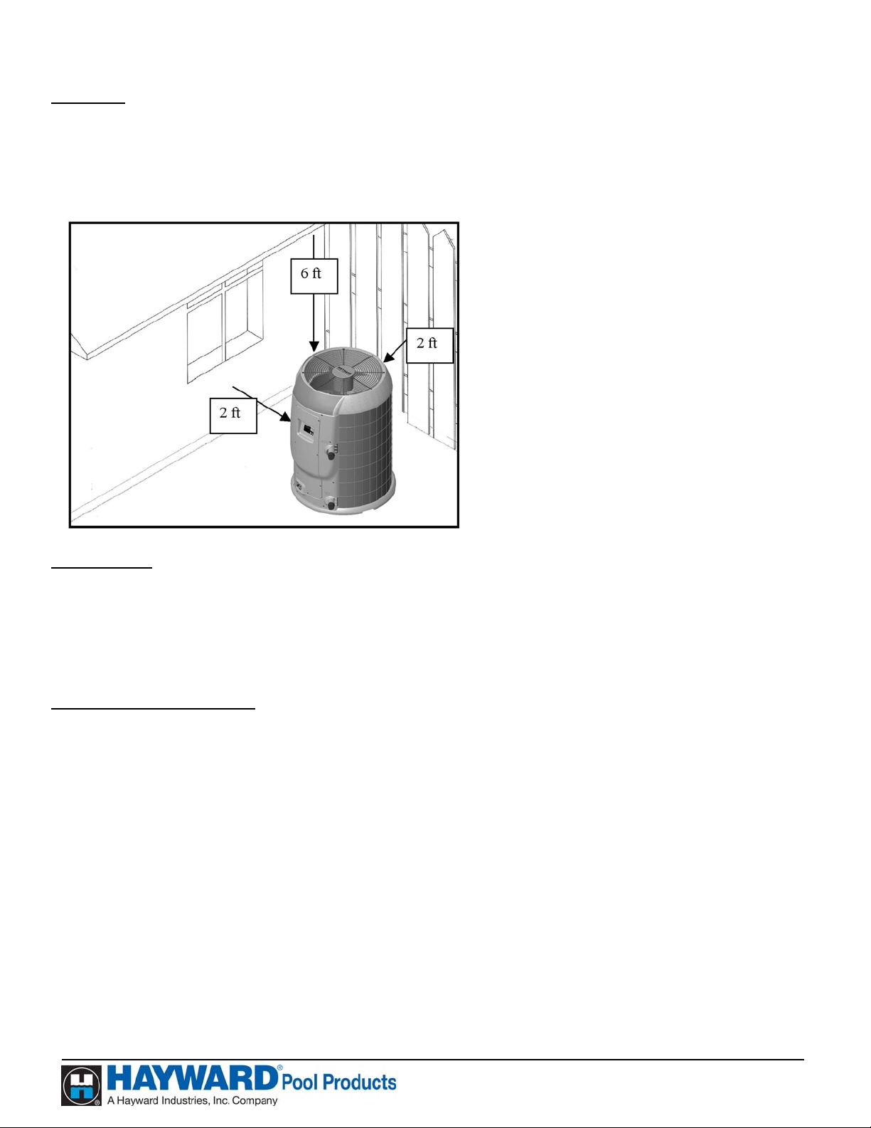
Clearance
A minimum of 2 feet (.6 m) of clearance from walls, shrubbery, equipment, etc. is required around the entire
heat pump. This allows for ample air intake. A minimum of 6 feet (2 m) of clearance above the heat pump is
required to prevent re-circulation of air. We recommend NOT placing the unit underneath eaves, decks, or
porches, as this causes re-circulation of air.
RE-CIRCULATION OF AIR BACK
INTO THE PUMP WILL
GREATLY REDUCE ITS EFFICIENCY
Roof Run-Off
NOTICE - Make sure the heat pump is not located where large amounts of water may run-off from the roof
into the unit. Sharp sloping roofs without gutters will allow massive amounts of rainwater, mixed with debris
from the roof to be forced through the unit. This will clog, damage, and corrode the unit.
NOTE: A gutter or down spout may need to be installed to protect the heat pump.
Drainage and Condensation
THE HEAT PUMP GENERATES WATER CONDENSATION DURING NORMAL OPERATION.
THIS SHOULD NOT BE MISTAKEN FOR A LEAK IN THE UNIT.
A drain hole is provided in the in base pan on the side of the unit opposite the controls for adequate removal of
condensation and rainwater. Condensation will be produced by the evaporator coil while the unit is running and
drain at a steady rate, usually
The more humid the ambient air, the more condensation will be produced. If drainage is above this range during
operation or if water continues to drain from the base when the heat pump is not in operation for more than an
hour, a leak in the internal plumbing may have occurred. The troubleshooting section provides
recommendations if a leak is suspected.
NOTICE: Keep the drain hole clear of debris and clean it regularly to remove any obstruction.
3 to 5 gallons per hour, depending upon ambient air temperature and humidity.
USE ONLY HAYWARD GENUINE REPLACEMENT PARTS
Pomona, CA Clemmons, NC Nashville, TN
Tel: 908.351.5400 www.haywardpool.com
Page 9

Page 9 of 24 HEATPRO HEAT PUMP HP13023772 Rev: B
NOTICE
Make sure there are no sprinkler heads near the heat pump that will spray on or into the unit.
Sprinkler damage is not covered under the warranty agreement.
Make sure that sprinklers are placed at a sufficient distance away, so that normal wind will not
carry the mist to the heat pump.
The heat pump is designed to handle the wettest weather conditions that are typical of rain and high humidity.
Sprinkler heads force high-pressure water into the unit from the side at an odd angle. Many sprinkler systems
are connected to a well system, whose water is high in minerals, sulphur, and other aggressive contaminates that
will leave a build up on the evaporator coils and electronics causing corrosion and hampering efficiency. If the
installed location is within 15 miles of the coast, salt may also be in the well water.
NOTICE- If in an oceanfront area, the heat pump should be placed out of direct spray of sand and salt.
This will clog, damage, and corrode the unit, which will void the warranty. You may also consider protecting
the unit by planting shrubbery or installing a privacy fence between the unit and the prevailing beachfront wind.
NOTICE – Damage caused by sand or salt spray will void the warranty.
POOL COVERS ARE STRONGLY RECOMMENDED
Using a Pool Cover
A pool loses heat in several ways and testing shows that evaporative cooling (the cooling effect created by
water evaporating from the surface of the pool) accounts for approximately 75% of a pool’s heat loss. However,
if a pool is covered when not in use, most evaporative cooling can be prevented. If the pool temperature is to be
maintained, the pool heating system must replace the heat lost, therefore the use of a pool cover can offer
dramatic savings in energy consumption. The cover’s approximate effect on pool losses is illustrated in the table
below:
Source of Heat Loss POOL UNCOVERED (USED 12HRS/DAY) POOL COVERED
Evaporative Cooling 75% 30%
Convection loss to air 15% 10%
Ground loss (dry earth) (Negligible – less than 1%) (Negligible)
Re-radiation to environment 9% 9%
Make-up water 1% 1%
Total 100% 50% of uncovered pool losses
As the table shows, a pool cover that reduces evaporative cooling can reduce the heat lost from a pool by
approximately 50% (which also reduces your power consumption by 50%).
USE ONLY HAYWARD GENUINE REPLACEMENT PARTS
Pomona, CA Clemmons, NC Nashville, TN
Tel: 908.351.5400 www.haywardpool.com
Page 10

Page 10 of 24 HEATPRO HEAT PUMP HP13023772 Rev: B
Operating the HeatPro Heat Pump
Start-Up Instructions
NOTICE- Do not use this heat pump if any part has been flooded or submerged. Immediately call a qualified
technician to inspect and replace any part of the heat pump control system that has been under water. Failure to
do so will cause property damage.
Before proceeding, MAKE CERTAIN there are no air or water leaks in any plumbing connections or piping
and water flow is within the proper flow rate ranges. The proper flow ranges for ALL Hayward HeatPro Heat
Pumps are a minimum of 30 GPM and a maximum of 75 GPM.
NOTE: Damage caused by flow rates outside this range will void the warranty.
CAUTION - Keep all objects off the top of the heat p ump. Blocking airflow could damage the unit
and will void the warranty.
Start-Up Procedures
After completing the electrical and piping connections to the pool heater, follow the procedures outlined below
to ensure that the pool heat pump is functioning properly.
1. Apply power to the pool heater by plugging in the non-fused disconnect block or moving the circuit
breaker to the “ON” position.
2. Place the pool heater thermostat in the “Standby” mode.
3. With the pool filter pump operating properly, push the “POOL” button to activate the unit and then set
the pool Heat Pump thermostat to the desired temperature.
4. Allow 5 Minutes for the Heat Pump to start.
5. When the unit starts, confirm that air is being discharged upward from the unit and the air is cooler than
the ambient air.
6. Allow the Heat Pump to operate for 10-15 minutes in order for system pressure to stabilize.
7. If Heat Pump fails to start:
Check water flow
a)
Ensure that power is On
b)
c) Refer to Performance Monitoring Section of this Manual
USE ONLY HAYWARD GENUINE REPLACEMENT PARTS
Pomona, CA Clemmons, NC Nashville, TN
Tel: 908.351.5400 www.haywardpool.com
Page 11

Page 11 of 24 HEATPRO HEAT PUMP HP13023772 Rev: B
p
ght
Becoming Familiar with HeatPro Heat Pump Controls
Display Window
Arrow Button
U
Down Arrow Button
Spa Button
(Optional)
Time Clock
Override Button
(Optional)
Heat Pump Control Panel
Pool Button Run Li
Display Window (All Models) When power is supplied to the unit, the display will either show
temperature (in degrees F or C), diagnostic code (such as
“rhd”), or scrolling dots.
Up Arrow Button (All Models) Raises the heat pump temperature set point.
Down Arrow Butto n (All Models) Lowers the heat pump temperature set point.
Pool Button (All Models) Activates the pool function of the controller.
Spa Button (All Models except HP11003T) Activates the spa function of the controller.
Run Light
Time Clock Override Button (Model
HP2100TCO3T only)
(All Models) Indicates the unit is operating normally and the thermostat is
making a demand for heat.
Activates the time clock override function of the controller.
USE ONLY HAYWARD GENUINE REPLACEMENT PARTS
Pomona, CA Clemmons, NC Nashville, TN
Tel: 908.351.5400 www.haywardpool.com
Page 12

Page 12 of 24 HEATPRO HEAT PUMP HP13023772 Rev: B
Control Operation
Dual Thermostat (Models HP6003T, HP21003T, HP21203T)
On/Off:
To enter Standby mode: If pool mode is active (indicated by the green led over the pool button), press
This control does not have a true on/off feature. The unit uses standby mode
instead. Scrolling dots in the display indicate standby.
Standby mode serves two
functions. (1) It serves as an “off” mode, which keeps the heat pump from
transferring heat into your pool water. (2)
Standby allows a pool owner with
remote controlling systems, such as Goldline, to maintain pool and spa
temperatures via the remote.
pool button once. Rolling dots should appear on the display. If spa mode is
the
active (indicated by the green led over the
once. Rolling dots should appear on the display.
spa button), press the spa button
To exit Standby mode:
Mode Selection:
Run Indicator Light:
Temperature Set point:
Adjust the set point:
To display the set point:
Press either the
pool or spa mode button.
Select the desired mode of operation (spa or pool) by using the POOL / SPA
buttons. A green LED above the buttons designates the active mode. When the
pool mode is active, any displays or adjustments apply only to the pool mode.
Adjustments for
user can switch between modes without turning the control to
spa mode must be made while the spa button is activated. A
standby first.
Shows the unit is operating normally and the thermostat is making a demand for
heat.
Pool and spa mode range is 50-104°F (21-40°C).
Continuing to hold the up or down arrow button will adjust the set point value
until the desired set point is reached. When the desired value has been reached,
release the button. The new set point will flash to indicate a new value has
been recognized and the display will revert back to water temperature as
indicated by a steady display.
Press and release the up or down arrow button once to display the current set
point for 3 seconds. For help with this type of control, refer to
Troubleshooting Guide with Digital Control.
USE ONLY HAYWARD GENUINE REPLACEMENT PARTS
Pomona, CA Clemmons, NC Nashville, TN
Tel: 908.351.5400 www.haywardpool.com
Page 13

Page 13 of 24 HEATPRO HEAT PUMP HP13023772 Rev: B
Single Thermostat (Model HP11003T)
Display:
When power is supplied to the unit, the display will either show temperature,
diagnostic code (such as “rhd”), or scrolling dots.
On/Off:
This control does not have a true on/off feature. The unit uses
instead. Rolling dots in the display indicate standby.
Standby mode serves two
standby mode
functions. (1) It serves as an “off” mode, which keeps the heat pump from
transferring heat into your pool water. (2)
Standby allows a pool owner with
remote controlling systems, such as Goldline, to maintain pool temperature via the
remote.
To enter
To exit
Run Indicator Light:
standby mode: Press the pool button once. Scrolling dots should appear on the display.
standby mode: Press the pool mode button.
Shows the unit is operating normally and the thermostat is making a demand for
heat.
Temperature Set point:
Adjust the set point:
Pool mode range is 50-104°F (21-40°C).
Continuing to hold the up or down button will scroll the set point value until the
desired set point is reached. When the desired value has been reached, release the
button. The new set point will flash to indicate a new value has been recognized
and the display will revert back to water temperature as indicated by a steady
display.
Note: The temperature reading displayed when the unit is in operation (run indicator light is present) displays
current water temperature.
the
To display the set point: Pressing and releasing the Temperature Set up or down button once will display the
current set point for 3 seconds. For help with this type of control, refer to Troubleshooting Guide with Digital
Control.
TCO Function (Model HP2100TCO3T)
Time Clock Override (TCO):
TCO provides a method of maintaining the pool temperature when a time clock has the pool filter pump turned
off. The TCO function then controls the pool filter pump. TCO will automatically turn the pool filter pump on
after 2 hours of “off time”. It will run the filter pump for 10 minutes while monitoring the water temperature. If
there is more than a 2
will energize and continue to run until the set point is satisfied.
NOTE: The 2-hour TCO checking interval cannot be adjusted.
°F (1°C) difference between the set point and the actual pool temperature the heat pump
USE ONLY HAYWARD GENUINE REPLACEMENT PARTS
Pomona, CA Clemmons, NC Nashville, TN
Tel: 908.351.5400 www.haywardpool.com
Page 14

Page 14 of 24 HEATPRO HEAT PUMP HP13023772 Rev: B
A user may temporarily override the TCO. An example would be if the pool were to be used between 9:00 and
10:00 pm. The control may be programmed to energize the filter pump, which will engage the heat pump to
maintain the pool temperature. This is a temporary measure that can be initiated in 30- minute increments, for a
period up to 9.5 hours.
Programming for Time Clock Override:
1) Push and hold TC OVRD Button – Display will read “P0.0”
Push up (RED) button – display will read “P0.5” and the TC OVRD light will be on.
2)
Note: Each time the up or down arrow button is pressed, the display will increase or decrease in “.5”
increments. Each increment equals 30 minutes, up to 9.5 hours (
Push down (BLUE) button to decrease the temporary override time. Continue decreasing the time until
3)
reaching
“P0.0” to turn the override off.
P9.5) maximum
Example of typical TCO cycle: When the time clock turns off the filter pump, a “PS” will show on the
display. A timer starts inside the controller. After 2 hours, the heat pump will start the filter pump to circulate
water. “PS” is removed from the display and if a demand for more heat is made, the heat pump goes back to
normal operation. The 2-hour timer is reset and the cycle will start over. For help with this type of control,
refer to Troubleshooting Guide with Digital Control
.
Changing Temperature Display (All Models):
The control will display temperatures in either degrees Fahrenheit or Celsius. To change the temperature
display, place the heat pump in “Stand-By” mode so that the scrolling dots appear on the screen. Press and
hold both the
pool button and the down arrow button for two seconds and release. Place the heat pump back in
pool or spa mode and the temperature change will be displayed. When viewing the temperature in degrees
Fahrenheit only the numeric temperature is displayed, but when viewing degrees Celsius the control will
display the numeric temperature followed by a lower case “c”.
Lock Out Feature (All Models):
A lock out function is provided to keep the temperature set point from being changed. To engage this function
in the
pool or spa mode press the up arrow button, down arrow button and pool button at the same time and
hold for 2 seconds. The control display will read “LOC” while the lock out function is engaged. To exit the
lock out function in
pool or spa mode press the up arrow button, down arrow button and pool button at the
same time.
Defrost Function (All Models):
This function is provided to prevent the evaporator coil from freezing up when the outside air temperature is
near 50°F (10°C). There is no exact temperature at which this function will operate, as each unit will vary
depending upon the surrounding conditions and outside air temperature. This time period will vary from 15
minutes to several hours depending on the outside air conditions.
USE ONLY HAYWARD GENUINE REPLACEMENT PARTS
Pomona, CA Clemmons, NC Nashville, TN
Tel: 908.351.5400 www.haywardpool.com
Page 15

Page 15 of 24 HEATPRO HEAT PUMP HP13023772 Rev: B
Maintenance
Water Chemistry
Proper chemical balances are necessary for sanitary swimming conditions as well as ensuring your heat pump’s
long life.
Sanitizing Equipment
Sanitizers, if used, MUST be installed downstream of the heat pump (in the return line to the pool) and a check
valve installed in a manner that will not allow the raw chlorine to drain back to the heat pump when the water
filter pump is off. This will prolong the overall life of the heat exchanger and the heat pump.
CHEMICALS DIRECTLY INTO THE SKIMMER.
DO NOT POUR
Inspection and Service
Hayward HeatPro heat pumps are designed and constructed to provide long performance life when installed and
operated properly under normal conditions. Periodic inspections are important to keep your heat pump running
safely and efficiently through the years.
Keep all objects off the top of the heat pump. Blocking airflow could damage the unit and void the
warranty.
Owner Inspection
Hayward recommends that you inspect your heat pump on a seasonal basis and especially after significant
weather events. Refer to the sections of this Manual: “Clearance”, “Roof Run-Off”, “Drainage and
Condensation” for proper inspection.
Professional Inspection
WARNING - RISK OF ELECTRIC SHOCK OR ELECTROCUTION. Before servicing heat pump or
motor, disconnect ALL electrical power. An EPA Certified service technician MUST perform inspection.
Note: Hayward recommends annual equipment inspections.
Note: Never use high-pressure water to clean evaporator coil fins, as this will cause damage to the coil.
Summertime Shutdown
For certain areas during the summer months, when the heat pump is not needed, you can place the heat pump in
standby mode.
End of Season (Winterizing)
Failure to properly winterize heat pump may result in serious equipment damage.
covered under the heat pump warranty.
Freeze damage is NOT
USE ONLY HAYWARD GENUINE REPLACEMENT PARTS
Pomona, CA Clemmons, NC Nashville, TN
Tel: 908.351.5400 www.haywardpool.com
Page 16

Page 16 of 24 HEATPRO HEAT PUMP HP13023772 Rev: B
While the plumbing connections are in the winterized condition (not fully tightened), it is imperative that the
pool / spa water is NOT circulated through the heat pump. Loss of water through loose plumbing connections
may result in damage to circulating pump, pool / spa structure and / or other equipment.
Many pool service companies offer “Winterizing” assistance. Hayward recommends using a professional
for this procedure.
• Perform the cleaning procedures recommended above.
• Disconnect the power supply (usually at the circuit breaker in your house).
Cover the heat pump to protect it from snow and water, which may freeze and damage the unit. If the pool is
being closed for the winter,
THE UNIONS AND DRAIN ALL WATER LINES. A drain plug is provided on the bottom water connection
BE ABSOLUTELY CERTAIN TO DISCONNECT THE HEAT PUMP FROM
on the heat exchanger (see figure below). Remove all excess water.
Some heat pump owners desire their pool to be heated during the winter months. This is possible when daytime
temperatures are above the low ambient temperature (near 50
°F [10°C]) for most of Hayward’s heat pumps.
If temperatures fall below freezing, be certain to keep the pool filter pump operating continuously to prevent
freeze damage.
Performance Maintenance and Troubleshooting
Service Procedures
Before Calling For Service
If there appears to be a problem, refer to the troubleshooting section on the following pages.
1. Ensure the swimming pool filtration system is turned on.
2. Ensure the main power circuit on.
3. Verify that the heat pump is not in stand-by mode (pool or spa indicator light is illuminated).
4. Ensure that the heat pump thermostat set at a high enough level to enable the system to turn on.
USE ONLY HAYWARD GENUINE REPLACEMENT PARTS
Pomona, CA Clemmons, NC Nashville, TN
Tel: 908.351.5400 www.haywardpool.com
Page 17

Page 17 of 24 HEATPRO HEAT PUMP HP13023772 Rev: B
5. Ensure the outside temperature is high enough to allow the unit to operate. Hayward heat pumps will not
turn on when the outside air temperatures drop near 50°F (10
6. Ensure that the pump and skimmer baskets are clean; also ensure that the pool filter is clean and
supplying proper water flow to the heat pump.
7. If the heat pump is not able to maintain the desired temperature, depending on the time of the year, it
may be necessary to adjust your pool filtration systems hours of operation (increase run time).
8. If the heat pump does not appear to be heating, check the air temperature being blown out of the top. If
the air coming out is cooler than the ambient air, the unit is functioning properly. If the two temperatures
are the same, there may be a problem.
Note: Use a solar blanket / cover on the surface of the pool in order to minimize heat loss.
Check the Electronic Display:
1. If diagnostic code “PS” is displayed, insufficient water flow may be the problem. Ensure that pool filter
pump basket, skimmer basket and filter are clean.
°C).
2. If diagnostic code “LP” is displayed, this may indicate that the outside temperature is too low (50-55°F
[10-13
rises sufficiently, the heat pump will automatically turn on.
3. If diagnostic code “HI” is displayed, this may indicate that an insufficient water flow condition exists.
Check that the pool pump strainer basket, skimmer basket and filter are clean. After checking these
items, if the “HI” indicator is still displayed, contact your original equipment installer or service
provider. If you do not have a service provider, a list of service providers may be found at
www.haywardnet.com/locator.
°C]). When this occurs, the Heat Pump turns off automatically. When the outside air temperature
USE ONLY HAYWARD GENUINE REPLACEMENT PARTS
Pomona, CA Clemmons, NC Nashville, TN
Tel: 908.351.5400 www.haywardpool.com
Page 18

Page 18 of 24 HEATPRO HEAT PUMP HP13023772 Rev: B
Troubleshooting
Circuit Breakers: If it is suspected that a circuit breaker is tripped, turn the breaker to the “Off” position and
then back to the “On” position. Visually checking the breaker is “On” is inadequate, as some switches move
only a short distance when tripped. Toggle the switch to “Off” then “On” every time you suspect the breaker is
tripped.
General Troubleshooting Guide for Hayward HeatPro Heat Pump
Problem Possible Cause Possible Solution(s)
No power to unit Make sure power is on.
Breaker is tripped Check the breaker / see note above
Thermostat not turned up
high enough
5 minute delay timer still
running
Unit is not operating.
Low water flow
Outside temperature too low
Fan not functioning Call Pool Service Provider.
Check output air temperature
Heat pump is running but
is not heating “Run” light
does not come on.
to input air temperature.
Differential should be
between 5 and 12 ºF
System Component failure. Call Pool Service Provider.
Thermostat set too high Turn thermostat down
Heat pump runs
continually
Electrical component failure
Bad valve or improper water
flow
Heat pump is cycling (on /
off too quickly)
Low refrigerant, low ambient
temp, or high humidity with
low ambient temp
Condensation This is normal and there is no reason to be concerned
Water is coming from
bottom of unit
Possible water leak
Turn thermostat up until unit comes on
Be sure the 5 minute delay has passed
Make sure filter is clean
Make sure filter pump is on
Unhook cleaning devices (skimmers, crawlers, etc.)
Check outside ambient temperature or wait for
warmer temperatures to operate. (refer to Operating
section)
Low ambient air temperature. Allow outside air
temperature to exceed 60ºF, and then re-check.
Turn off the filter pump. If the unit is still running
after 2 minutes, turn off the power to the unit and call
Pool Service Provider.
Check valve settings and ensure water flow is
sufficient (is the filter pump running continually?) If
heat pump continues to cycle, turn unit off to prevent
compressor damage.
Check evaporator coil for severe frost. Turn unit off to
prevent compressor damage.
If heat pump continues to cycle, turn unit off to
prevent compressor damage- and call Pool Service
Provider.
Turn the unit off for several hours, but leave the filter
pump running continuously. If water discharge
ceases, then it is only condensation. Otherwise there is
a possible leak.
USE ONLY HAYWARD GENUINE REPLACEMENT PARTS
Pomona, CA Clemmons, NC Nashville, TN
Tel: 908.351.5400 www.haywardpool.com
Page 19

Page 19 of 24 HEATPRO HEAT PUMP HP13023772 Rev: B
Display diagnostic codes - Troubleshooting Guide for Hayward HeatPro Heat Pump
Display Problem Possible Cause Solution
No power to heat
(Blank)
★
PS
LP Low Pressure Switch Air flow obstruction
HI High Pressure Switch
SH Temperature sensor Failure Call Pool Service Provider.
OP Temperature sensor Failure Call Pool Service Provider.
888 Thermostat reset Normal operation
rhd
pump
Faulty electrical
component
Unit will not turn on 5-minute delay Wait 5 minutes
Water Pressure
Switch
Tripped circuit breaker/
no power supply
Call Pool Service Provider.
Low or no water flow
Low water flow
High water temp
Remote device is
controlling the unit.
Check breaker and ensure that the unit is properly
installed.
Check water flow to heat pump
Clean the filter
Make sure all valves are open and bypass valve is
closed
Ensure pool filter pump is on
Normal operation for TCO function
Turn off fountains, etc.
Perform cleaning procedures described in this manual.
Call Pool Service Provider.
Check water flow to heat pump. .
Clean the filter
Make sure all valves are open and bypass is closed.
Ensure pool filter pump is on and turn off fountains.
Set unit to “ACP” if the unit has the heat / cool option.
Refer to text on HP3100 control board.
Check pool temp. Wait until pool needs heat.
Call Pool Service Provider.
Temporary display. Shows for 1-2 seconds when the
unit is first turned on.
Refer to owner’s manual of the remote device.
If a remote device is not connected. Call Pool Service
Provider.
PST Push button stuck Release button is stuck. If button does not release. Call Pool Service Provider.
PNL
CEL
CHC Board self-check error Board Failure Call Pool Service Provider.
dEF Defrost Mode
cOP Coil Sensor Sensor Failure Call Pool Service Provider
cSH Coil Sensor Sensor Failure Call Pool Service Provider
Control not receiving
data from panel
Panel not receiving
data from control
Control communication
problem.
Control communication
problem.
Frost build up on
evaporator coil.
Call Pool Service Provider.
Call Pool Service Provider.
No action required. Unit is defrosting automatically.
USE ONLY HAYWARD GENUINE REPLACEMENT PARTS
Pomona, CA Clemmons, NC Nashville, TN
Tel: 908.351.5400 www.haywardpool.com
Page 20

Page 20 of 24 HEATPRO HEAT PUMP HP13023772 Rev: B
Heat Pump Replacement Parts Diagram
CONTROL BOX FOR:
HP6003T, HP11003T,
HP21003T AND
HP21203T
CONTROL BOX FOR:
HP2100TCO3T
USE ONLY HAYWARD GENUINE REPLACEMENT PARTS
Pomona, CA Clemmons, NC Nashville, TN
Tel: 908.351.5400 www.haywardpool.com
Page 21

Page 21 of 24 HEATPRO HEAT PUMP HP13023772 Rev: B
Heat Pump Replacement Parts List
Item Part description HP21203T HP21003T HP2100TCO3T HP11003T HP6003T
FAN TOP
1
2 SIDE PANEL
CONTROL BOX COVER
3
4 CONTROL BOX
CONTACTOR
5
6 CONTROL BOARD ASSY HPX26024140 HPX26024138 HPX26024139
INTERFACE BOARD
7
WATER PRESSURE SWITCH
8
TRANSFORMER
9
CAPACITOR HPX11024155
10
BENT COIL with GUARD
11
COMPRESSOR HPX11023911 HPX11024077
12
13 CONDENSER
COVER GASKET
14
15 HPC CABLE (NS)
FAN MOTOR, 1/3 HP
16
17 FAN GUARD
COMPRESSOR BLANKET (NS)
18
19 -
FAN BLADE
20
21 REPLACEMENT HP SWITCH
REPLACEMENT LP SWITCH
22
EXPANSION VALVE ASSY HPX15024026
23
24
TEMPERATURE SENSOR
25
SCREW REPLACEMENT KIT (NS)
26
COMPRESSOR MOUNT KIT (NS)
27
28 COMPRESSOR EL. PLUG (NS)
ELECTRICAL ENTRY PLUG
29
30 DRAIN PLUG
FAN RUN CAPACITOR
31
32 DEFROST SENSOR
-
HPX26024139
HPX15024023
HPX01023502
HPX01023503
HPX01023504
HPX01023505
HPX1985
HPX11024130
HPX2181
HPX11023693
HPX11024154
HPX24023929
HPX11024170
HPX24023941
HPX05023549
HPX10023517
HPX11023564
HPX01023561
HPX02024108
-
HPX15023562
HPX2186
HPX2179
-
HPX2169
HPXSCRKIT1
HPX0054
HPX2223
HPX01023760
SPX4000FG
HPX11024151
HPX11024169
USE ONLY HAYWARD GENUINE REPLACEMENT PARTS
Pomona, CA Clemmons, NC Nashville, TN
Tel: 908.351.5400 www.haywardpool.com
Page 22

Page 22 of 24 HEATPRO HEAT PUMP HP13023772 Rev: B
NOTES:
_____________________________________________________________________________
_____________________________________________________________________________
_____________________________________________________________________________
_____________________________________________________________________________
_____________________________________________________________________________
_____________________________________________________________________________
_____________________________________________________________________________
_____________________________________________________________________________
_____________________________________________________________________________
_____________________________________________________________________________
_____________________________________________________________________________
_____________________________________________________________________________
_____________________________________________________________________________
_____________________________________________________________________________
_____________________________________________________________________________
_____________________________________________________________________________
_____________________________________________________________________________
_____________________________________________________________________________
_____________________________________________________________________________
USE ONLY HAYWARD GENUINE REPLACEMENT PARTS
Pomona, CA Clemmons, NC Nashville, TN
Tel: 908.351.5400 www.haywardpool.com
Page 23

Page 23 of 24 HEATPRO HEAT PUMP HP13023772 Rev: B
HAYWARD® HEAT PUMP POOL HEATERS LIMITED WARRANTY
The HAYWARD heat pump pool heater is warranted to be free of defects in materials and workmanship for a period of
two (2) years for parts and (1) one year for labor. In the state of Florida, warranty labor is covered for (2) years. This
warranty is applicable to the original location and owner only and is not transferable. The compressor component has a
five (5) year limited warranty with parts and labor warranted the first two (2) years and parts only warranted in years
three (3), four (4) and five (5). The titanium tube component of the heat exchanger has a ten (10) year warranty.
HAYWARD will not void this warranty due to improper pool chemistry. This warranty is valid only if the product is
installed according to the HAYWARD specifications.
This warranty does not include refrigerant or other expendable materials, or services such as inspection, maintenance,
or unnecessary service calls due to erroneous operational reports, external valve position, or electrical service. It also
does not include the repair of damage due to negligence, accident, freezing, or other conditions beyond the normal
intended use of the unit. This warranty is void if the product is repaired or altered in any way by any persons or
agencies other than those authorized by HAYWARD, and is in lieu of all other warranties, expressed or implied,
written or oral. There are no implied warranties of merchantability or fitness for a particular purpose that apply to this
product. This warranty applies only within the continental USA. For warranty outside the continental USA, contact
HAYWARD.
At its option, HAYWARD will replace or repair any HAYWARD part that proves defective if such parts are returned
to our factory, freight collect, within the warranty period. It is agreed that such replacement or repair is the exclusive
remedy available from HAYWARD. Unless authorized by HAYWARD and performed by a factory authorized service
center, HAYWARD is not liable for any labor involved in the removal of defective parts or the installation of
replacement parts. HAYWARD is not liable for damages of any sort whatsoever, including incidental and
consequential damages. Parts returned and services performed under terms of this warranty must be approved by
HAYWARD. All parts returned under terms of this warranty will be repaired or replaced and returned transportation
charges prepaid, by best and most economical means.
This warranty applies to units shipped after July 14, 2008
Hayward Pool Products, Inc.
620 Division Street
Elizabeth, NJ 07207
Retain this Warranty Certificate in a safe and convenient location for your records
USE ONLY HAYWARD GENUINE REPLACEMENT PARTS
Pomona, CA Clemmons, NC Nashville, TN
Tel: 908.351.5400 www.haywardpool.com
Page 24

Page 24 of 24 HEATPRO HEAT PUMP HP13023772 Rev: B
▼DETACH HERE: Fill out bottom portion completely and mail within 10 days of purchase/installation.
USE ONLY HAYWARD GENUINE REPLACEMENT PARTS
Pomona, CA Clemmons, NC Nashville, TN
Tel: 908.351.5400 www.haywardpool.com
 Loading...