

Hayward HL32950VVSP, HL26720VSP, HL23520VSP, HL32900VSP, HL23510VSP Installation Manual

Hayward Pool Products
620 Division Street, Elizabeth NJ 07207
Phone (908)-355-7995
www.hayward.com
VS Omni
Pool Automation Control
Installation Manual
HL32950VVSP HL32900VSP
HL26720VSP HL23520VSP
HL23510VSP
Contents
Before you Begin.....................3
Mounting...............................7
Plumbing................................9
Wiring...................................10
Startup................................22
Conguration........................22
092680 RevB
USE ONLY HAYWARD GENUINE REPLACEMENT PARTS

FCC Statement
This device complies with part 15 of the FCC rules. Operation is subject to the following two conditions:
(1) This device may not cause harmful interference, and (2) this device must accept any interference
received, including interference that may cause undesired operation.
Changes or modifications not expressly approved by Hayward could void the user’s authority to
operate this equipment.
NOTE: This equipment has been tested and found to comply with the limits for a Class B digital device,
pursuant to Part 15 of the FCC Rules. These limits are designed to provide reasonable protection
against harmful interference in a residential installation. This equipment generates, uses and can
radiate radio frequency energy and, if not installed and used in accordance with the instructions, may
cause harmful interference to radio communications. However, there is no guarantee that interference
will not occur in a particular installation. If this equipment does cause harmful interference to radio
or television reception, which can be determined by turning the equipment off and on, the user is
encouraged to try to correct the interference by one or more of the following measures:
-- Reorient or relocate the receiving antenna.
-- Increase the separation between the equipment and receiver.
-- Connect the equipment into an outlet on a circuit different from that to which the receiver is
connected.
-- Consult the dealer or an experienced radio / TV technician for help.
Industry Canada Statement
This Class B digital apparatus complies with Canadian ICES-003.
Cet appareil numérique de la classe B est conforme à la norme NMB-003 du Canada.
The term “IC” before the certification / registration number only signifies that the Industry Canada
technical specifications were met.
1
USE ONLY HAYWARD GENUINE REPLACEMENT PARTS

Table of Contents
Before you Begin.......................................................................................................3
Overview..................................................................................................................4
Mounting
VS Hub.............................................................................................................7
Control Pad.......................................................................................................7
Smart Relay......................................................................................................8
Temperature Sensors........................................................................................9
Plumbing.................................................................................................................9
Electrical Wiring
High Voltage...................................................................................................11
Low Voltage....................................................................................................13
System Startup.........................................................................................................22
Configuration
Pre Programmed Configuration........................................................................25
Typical Configuration.......................................................................................25
Advanced Configuration..................................................................................27
Quick Edit..............................................................................................................42
Control Pad Mounting Template.................................................................................50
USE ONLY HAYWARD GENUINE REPLACEMENT PARTS
2
USE ONLY HAYWARD GENUINE REPLACEMENT PARTS
2

Before you Begin
What’s Included
Check that the following components have been included in your package:
• VS Omni Hub
• Control Pad
• Smart Relay
• 2 Temperature Sensors
• Variable Speed Pump (VSP)
• 15 ft, 3 conductor (red, black and bare wire) communication cable to connect Hub to VSP
• 2 Wiring Whips - 6 ft flexible conduit containing three 12AWG conductors (red, black and
green) for wiring VSP to VS Omni Hub and for Smart Relay installation). A length of white 12
AWG conductor is included to replace red for 115V Smart Relay applications
• Input Power Wiring harness and miscellaneous installation hardware
What’s NOT Included
Some of the additional items that you may need to complete an installation include:
Wire
Wire/conduit for incoming power
Wire for remote heater control and other low voltage devices
Ethernet cable (if not using wifi)
Miscellaneous
Valve actuator to automate pool functions (see page 9)
Flow switch for pump protection/flow monitoring
Mounting hardware for mounting Hub, Control Pad and Smart Relay
Cable/cord connectors to provide knockout strain relief
Wire nut connectors
USB thumbstick (to update firmware)
Tools Needed
Philips and flat screwdrivers
Wire cutters and strippers
Knife to cut conduit
Drill and drill bits (including 3/8")
Pliers
Level
Accessory Products - Order Separately
HLH485RELAY Smart Relay used for controlling additional pool equipment
FLO Flow Switch used to detect water flow
GVA-24 Valve Actuator
2PC Temperature Sensor for 3rd input
3
USE ONLY HAYWARD GENUINE REPLACEMENT PARTSUSE ONLY HAYWARD GENUINE REPLACEMENT PARTS

Overview
The Hayward VS Omni is a web enabled pool automation control with a convenient touchscreen
interface. Because it's packaged with a high efficiency variable speed pool filter pump, the VS Omni
is ideal for both retrofit and new pool/spa installations. Automatically and remotely control pumps, a
heater, a valve actuator, pool and yard lighting, and more. The VS Omni offers the next generation of
technology to manage pool/spa equipment, allowing communication to web connected computers
and mobile devices. You can now conveniently monitor your pool/spa and change settings anytime,
and from anywhere.
Please read through this manual thoroughly before attempting to install, configure or operate this
unit. A Quick Start guide is also included to offer concise information to experienced installers.
Features
The standard Hayward VS Omni offers the following functionality:
• controls up to 2 variable speed pumps for pool/spa filtration and water features
• controls up to 2 Smart Relays to turn on/off single speed pumps, pool lights, yard lights, water
features, chemical dispensers and more
• controls up to two valve actuators allowing you to manage two bodies of water (both pool and
spa) or can be used for water features, cleaners, solar heating, etc. (currently requires Hub to be
powered by 230 VAC)
• controls one conventional heater (electric heatpump or gas) and optional solar heater (for single
body of water applications only)
• inputs for up to 3 temperature sensors or external input devices
• built-in wireless to connect to the home’s router/access point (ethernet port provided for optional
wired connection)
• optional flow switch used to protect pool equipment by detecting water flow
Optional accessories (page 3) can expand the functionality of the VS Omni. Determine your needs
and select the necessary accessories before you begin the installation.
Equipment
VS Omni Hub
All incoming/outgoing wiring will be connected to the Hub. The VS Omni Hub can be powered by
either 115 VAC or 230 VAC. Input power should be constant, not from a timer. If a timer must be
used, set the timer to power the Hub continuously. For convenience, a 6ft Wiring Whip is included
with the VS Omni. This whip is intended to connect the Hub's input power to the variable speed
pump if using 230 VAC. This connection should be made inside of the Hub and will ensure that both
the Hub and pump are powered continuously.
The remaining connections, including the Control Pad, are all low voltage. Depending on your installation, these connections could be to a heater, Smart Relays, temperature sensors, actuator and a
flow switch.
USE ONLY HAYWARD GENUINE REPLACEMENT PARTS
4
USE ONLY HAYWARD GENUINE REPLACEMENT PARTS
Control Pad
The Control Pad is weather resistant and comes with a 15 ft cord. Its resistive touch screen with
flip down cover is designed to function year round directly in the elements. Because it plugs into the
Hub, it should be mounted close by, but in a location that is convenient for the user to periodically
view and change pool/spa settings.
The Control Pad features a USB connector for firmware updates and an Ethernet connector for an
optional direct connection to your router (if wifi won't be used).
Smart Relay
Smart Relays have 15 ft cable that wire to the Hub. They're used to control high voltage 115 or 230
VAC pool equipment like lights, water features, pumps and more. Power to the intended load must
be supplied separately and run through the Smart Relay. Smart Relays are rated for up to 20 amps
at 230 volts.
Temperature Sensors
Depending on your installation, up to 3 temperature sensors may be used. The VS Omni requires
a water temperature sensor for heater operation. If freeze protection is desired, an air temperature
sensor is also required. For solar heating systems, a solar sensor is necessary. Even if your installation doesn't require the use of temperature sensors, installing water and air sensors provides a
convenience to the user, especially during remote use.
Flow Switch (not included)
An optional flow switch can be used to detect leaks or clogs in the pool/spa plumbing.
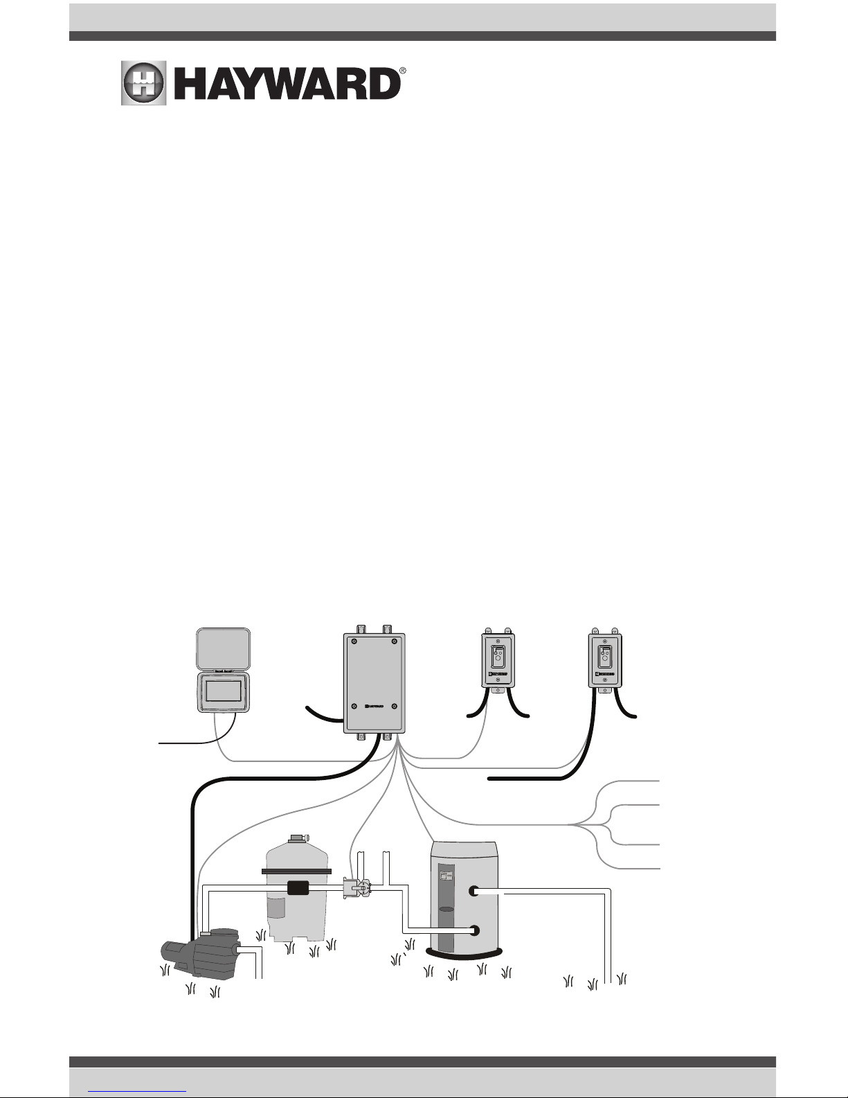
Input Power or
Existing Timeclock
Wiring Hub
(Optional)
Smart Relay 2
To Feature,
Accessory,
Lights, etc.
Variable
Speed Pump
Filter
Valve
Actuator
Heater
TO
POOL
FROM
POOL
Power
to VSP
Input Power to
Smart Relay 1
Comm. to Smart
Relay 1 (15’)
Comm. to
Heater
Comm. to
Valve Actuator
Comm.
to VSP
To Solar
REMOTE
RELAY
OFFLINE:
ON/OFF
Smart Relay 1
Input
Power
Comm. to Smart
Relay 2 (15’)
Control Pad
To Feature,
Accessory,
Lights, etc.
Wireless
Connection
OR
Ethernet to
Router
Comm. to
Controller (15’)
Sensor 1
(Water Temp.)
Sensor 2
(Air Temp.)
Sensor 3 (Solar OR
External Input)
(Optional)
Flow Switch
REMOTE
RELAY
OFFLINE:
ON/OFF
Wiring Whip
5
USE ONLY HAYWARD GENUINE REPLACEMENT PARTS

Installation
Installation Steps
DANGER of Death, Injury or Property Damage if procedure not followed. Power wiring must
be shut off before attempting to install the VS Omni.
The VS Omni is designed to be mounted outdoors at the pool pad. Both the Hub and the Control
Pad are water resistant and can be left out for the winter. Details on each installation step are
shown below:
1. Mounting the equipment (page 7)
VS Omni Hub
Control Pad
Smart Relay
Temperature sensors
Valve actuators (if applicable)
2. Plumbing (page 9)
General Pool Equipment
Flow Switch
3. Electrical Wiring (page 10)
Hub power
Grounding
Low voltage wiring (Pool Pump Communication, Heater, Smart Relays, Temperature Sensors,
Flow Switch, etc.)
5. System Startup and Firmware Upgrade (page 22)
The most common installation technique is described in the included Quick Start Guide. Use this
guide if possible. If the Guide can not be applied to your particular installation, refer to the additional
information in this manual.
USE ONLY HAYWARD GENUINE REPLACEMENT PARTS
6
Mounting the Equipment
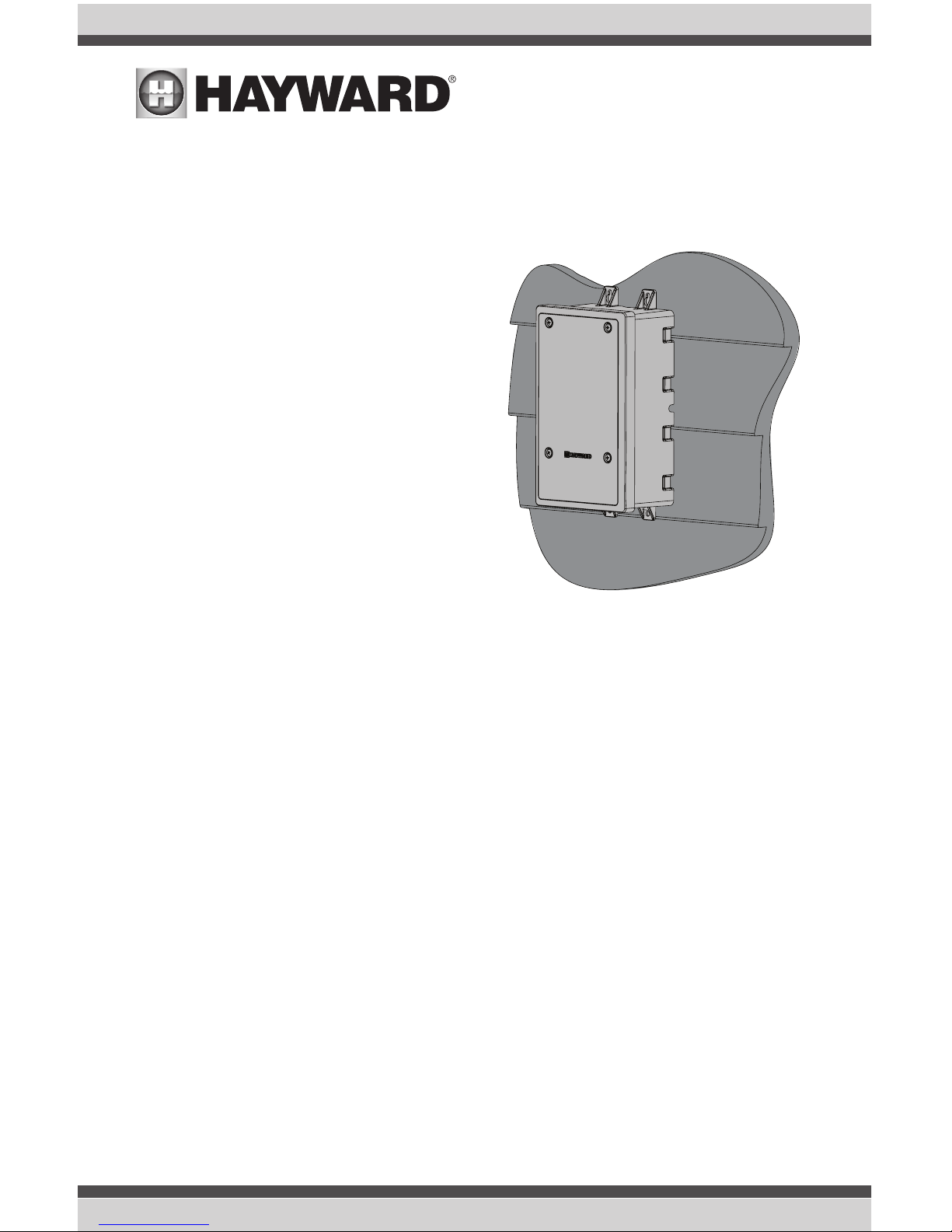
VS Omni Hub
The Hub is contained in a raintight enclosure
that is suitable for outdoor mounting. It must
be mounted a minimum of 6 ft (2 meters) horizontal distance from the pool/spa (or more, if
local codes require). The Hub is designed to
mount vertically with the knockouts facing
downward. Do not mount the Hub inside a
panel or tightly enclosed area.
When selecting a location, note that the standard cables supplied with the optional flow
switch, temperature sensors, and actuators
are all 15 ft (5m) long. Additional low voltage connections will have to be made to the
pump and/or heater. 115 VAC or 230 VAC input power must also be run to the Hub. Try to
mount the Hub in a location where incoming/
outgoing wiring will be easily accessible.
Mount the Hub on a wall or flat surface. Select
mounting hardware that is appropriate for the
mounting surface and material. The Hub has two keyhole type mounting tabs on the top and bottom
of the enclosure requiring a total of 4 fasteners.
Control Pad
The Control Pad comes with a 15 ft cord and plugs into the Hub. It should be mounted in a location
that is convenient for the user to view and change pool/spa settings. When considering the mounting location, make sure there is enough clearance above the enclosure so that the flip door will be
able to be opened fully. Also be sure to allow enough clearance below the Control Pad to access
the USB and Ethernet connectors. For best viewing results, position the Control Pad where it won't
be subjected to direct sunlight.
The Control Pad has two keyhole cutouts on the back of its enclosure. To mount, screw the two
provided fasteners into the mounting surface at the desired location using the template found on
page 54 . Tighten until the bottom of the screw heads are 1/8" off the mounting surface. Position
the Control Pad cutouts over the screw and slide the unit downward. You may have to tighten or
loosen the screws slightly to fully engage the screw heads to get a snug fit.
7
USE ONLY HAYWARD GENUINE REPLACEMENT PARTS
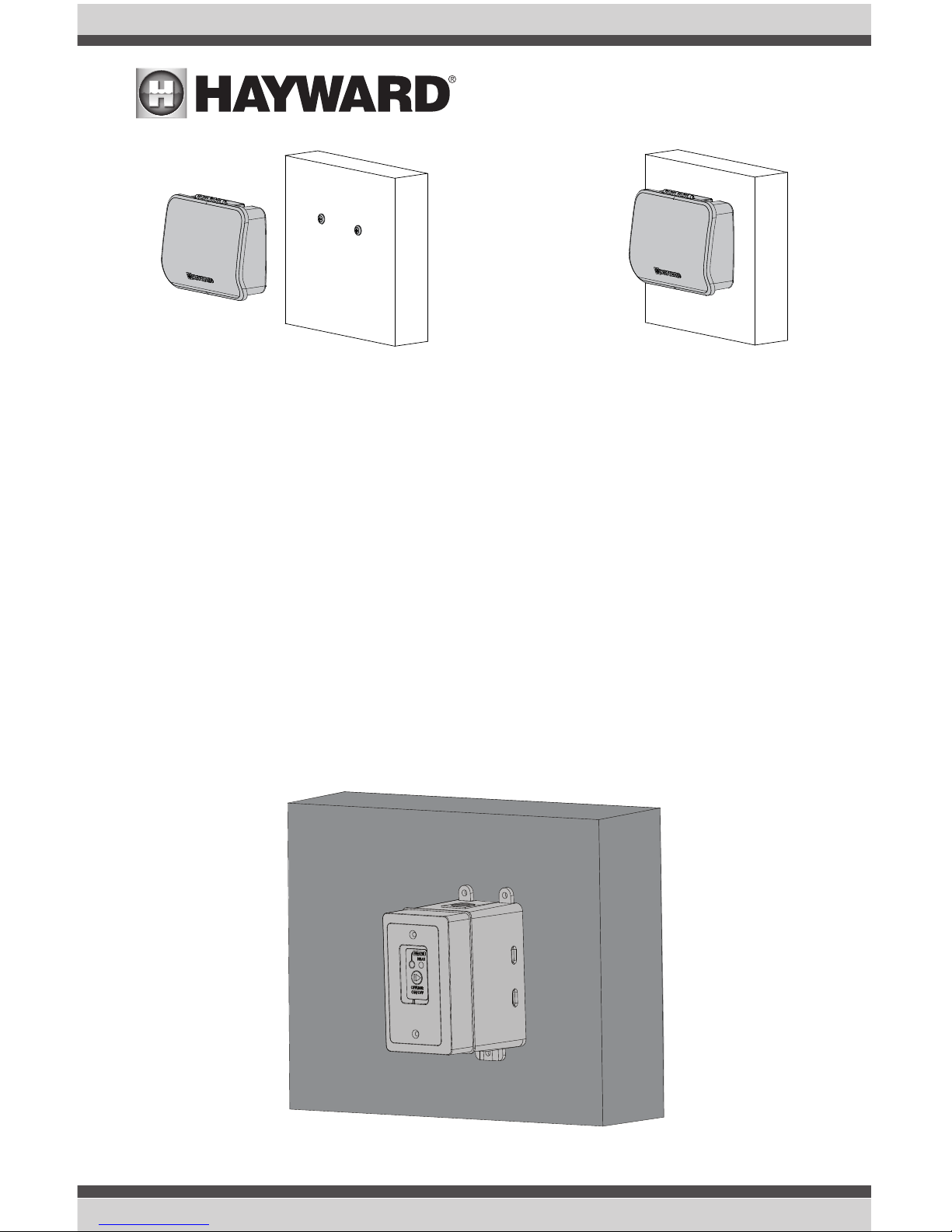
Smart Relay
The Smart Relay is packaged with a single gang electrical box but can also be used with any existing
comparable standard electrical box with a minimum volume of 16.2 in3. If using 115 VAC, make
sure that there is a Neutral line inside the box before installation. If not, you must run a separate
Neutral wire to power the Smart Relay. This is not a concern if using 230 VAC. Note that conduit and
connections to the included plastic box must be non-metallic.
Find a location within 15 ft of the Hub with convenient access to the pool equipment that you intend
to control with the Smart Relay. Three threaded 1/2" NPT knockouts are provided for high voltage
power coming into the relay and for power out to the pool equipment. A Wiring Whip is included to
aid installation.
The Smart Relay has a manual On/Off button that can be used if communication is lost with the Hub.
Although this button is not functional during normal operation, mount the Smart Relay in an accessible location to use this feature in case of communication loss.
Mount the Smart Relay to a wall or other flat surface using the mounting holes which are designed
to accommodate #8 screws.
USE ONLY HAYWARD GENUINE REPLACEMENT PARTS
8

Temperature Sensors
Water Sensor
This sensor is used to measure the pool/spa temperature and is installed in the filtration plumbing
after the filter but before either the solar or conventionally fueled heaters.
1. Drill a 3/8” (10mm) diameter hole in the PVC piping and remove all chips and burrs.
2. Insert sensor until O-ring collar sits flush on the hole.
3. Position hose clamp over the sensor and gently tighten until O-ring makes an adequate seal.
Do not overtighten.
Air Sensor
Mount the air sensor outdoors. IMPORTANT: The air sensor must not be mounted in direct sunlight.
Solar Sensor
For solar applications, mount the sensor near the solar collector array so that it is exposed to the
same sunlight as the collectors. Use additional cable (20 AWG) if necessary.
Optional Valve Actuators
Currently, using an Hayward GVA-24 actuator or equivalent requires that the Hub be powered with
230 VAC. If powering the VS Omni Hub with 115 VAC, an actuator can't be used. For installation,
refer to the mounting instructions included with the unit. After configuring and first operating the
valve, note that the internal cams in the actuator may have to be adjusted depending on the way the
actuator is mounted on the valve and the desired valve action.
Plumbing
Optional Flow Switch
Only applicable if leak/clog detection is desired. The flow switch should be plumbed on the return
side at the very end of the pool pad plumbing. This will ensure that if a leak occurs anywhere at the
pool pad, the VS Omni will be able to detect it. Understand that if a leak occurs after the flow switch
(downstream), the VS Omni will not sense a no flow condition.
IMPORTANT: There must be at least a 12” (30cm) straight pipe run before (upstream) the flow switch.
IMPORTANT: To ensure proper operation, verify that the arrow on the flow switch points in the direction of water flow.
Variable Speed Pump
Refer to the included VS Omni Pump manual for plumbing information.
9
USE ONLY HAYWARD GENUINE REPLACEMENT PARTS
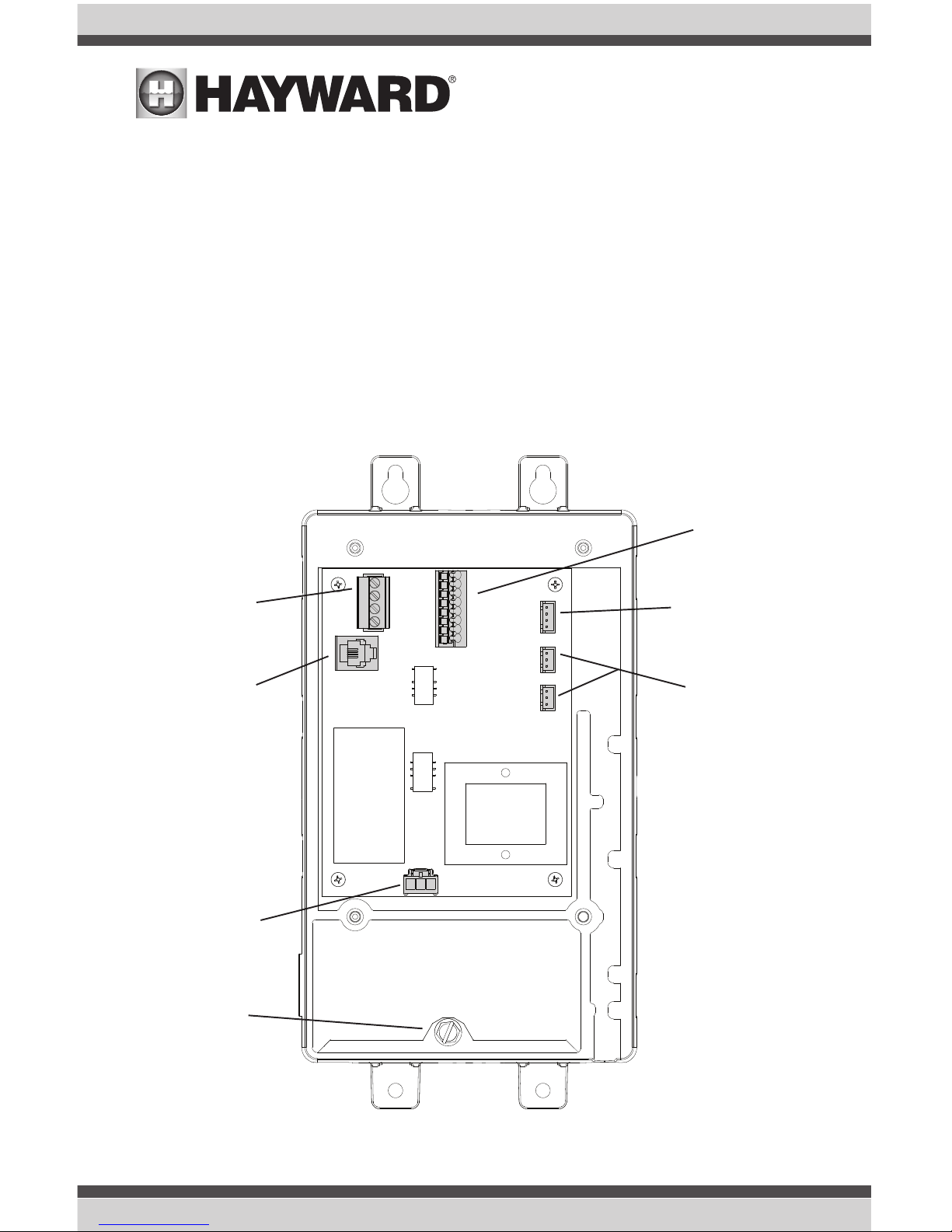
Electrical Wiring
The Hub requires both high and low voltage connections. Always:
- Ensure that Power is disconnected prior to performing any wiring
- Follow all local and NEC (CEC if applicable) codes
- Use copper conductors only
A dedicated channel on the right side of the Hub has been provided for all low voltage wiring. All low
voltage wires should run through this channel to exit the Hub. A weather resistant gasket is provided
(see page 21) to seal this exit.
Input Power
Flow Switch
Smart Relays
&
Variable Speed Pump
Communication
Temperature Sensors,
External Input
& Heater
Control Pad
Valve Actuators
(Hub must be powered by
230 VAC)
Wiring Channel
Low Voltage
Ground Screw
USE ONLY HAYWARD GENUINE REPLACEMENT PARTS
10
High Voltage Wiring
Hub Input Power
The Hub requires a constant 115 VAC or 230 VAC input power to operate. A wiring harness is included and will plug into the input power connector shown on page 10. Wire the harness according
to the diagram below.
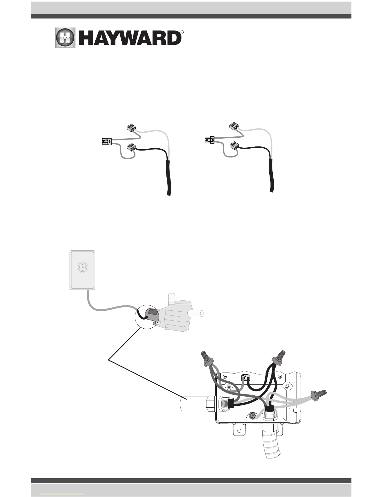
For easy installation, if replacing an existing 230 VAC pump, disconnect power at the pump and use
that connection to provide power to both the Hub and the new variable speed pump (VSP). Use the
included Wiring Whip to aid in this connection. The diagram below shows an existing timeclock used
to power the old pump. This configuration can be easily modified to power the VS Omni and the new
VSP. Refer to the diagrams below.
115 VAC
L1
N
230 VAC
L1
L2
Connect to Hub and
new Variable Speed
Pump (VSP)
L1
L2
Ground
Disconnect from existing
230 VAC pump
Wiring Whip to
VSP
230 VAC
Existing Timeclock
11
USE ONLY HAYWARD GENUINE REPLACEMENT PARTS
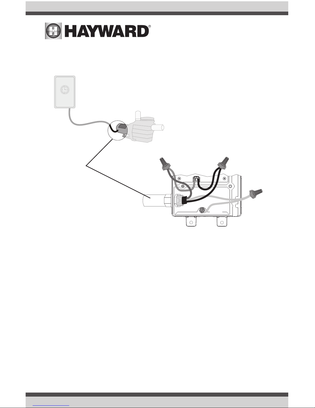
If replacing a 115 VAC pump, you can disconnect power at the pump and use it to power the Hub
only. The new variable speed pump however, requires 230 VAC which will have to be run separately.
Refer to the included pump manual for input power wiring.
If using an existing timeclock to power the Omni VS Hub, set it to run constantly. If the VS Omni Hub
will be connected to a panel or switch, the power will have to be left on continuously.
Grounding
Connect a ground wire from the primary electrical panel to the Hub's ground connection as shown in
the previous diagrams. Also ground each piece of high voltage equipment that is connected through
the Hub or Smart Relay.
Variable Speed Pump Input Power
The VS Omni pump requires a constant 230 VAC, 60Hz input power whether from the VS Omni Hub
using the Wiring Whip or directly from a service panel/switch. Refer to the VS Omni Pump manual for
the location of the wiring terminals as well as other related high voltage wiring information.
Connect 115 VAC to Hub
only and run 230 VAC
separately to the new
VSP
Neutral
Disconnect from existing
115 VAC pump
L1
Ground
115 VAC
USE ONLY HAYWARD GENUINE REPLACEMENT PARTS
12
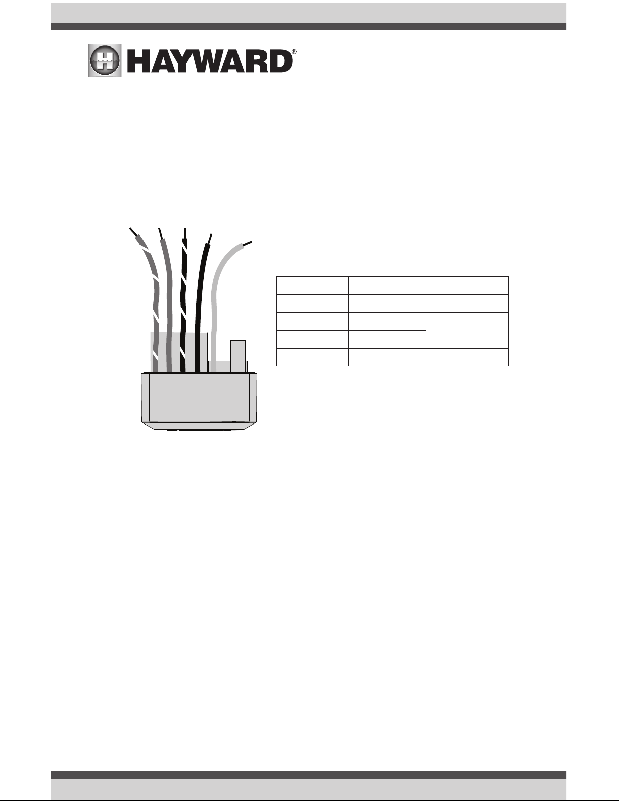
Smart Relay Load Wiring
A Smart Relay can be used to control either 115 or 230 VAC pool equipment. The relay is double pole
(makes/breaks both “legs” of 230V circuits or one "leg" of 115V circuits). Refer to the diagram below
for wire connections. Use the included Wiring Whip if the supplied electrical box will be mounted
within 6 ft of the power source. Red, black and green conductors are included for 230 VAC and a
white conductor is supplied if using 115 VAC input power. Use the included wire nuts for wiring connections. Use proper threaded strain relief fittings for conduit attached to knockouts. After wiring is
complete, carefully insert the cover with connections into the box and secure.
Low Voltage Wiring
Note: There is a low voltage channel on the right side of the Hub's enclosure labeled on page 10
and shown on page 21. All low voltage wiring that exits the Hub must run through this channel. The
included foam gasket (page 21) should be used to seal the channels's exit after wiring is complete.
Do not run low voltage wiring through a knockout or with any high voltage wiring.
Hayward Variable Speed Pump (VSP) Wiring
A separate VSP pump manual has been included with the VS Omni. For low voltage communication
wiring information, refer to the pump manual.
Gray
Black
Black/White
Red
Red/White
Red
Red/White
Black
Black/White
Gray
Neutral
Load out
No Connection
No Connection
115 VAC
Load 2 out
Load 1 out
Line 1 in
230 VAC
Line in
Connect Gray &
Red to Line 2 in
Smart Relay
Wire Colors
13
USE ONLY HAYWARD GENUINE REPLACEMENT PARTS
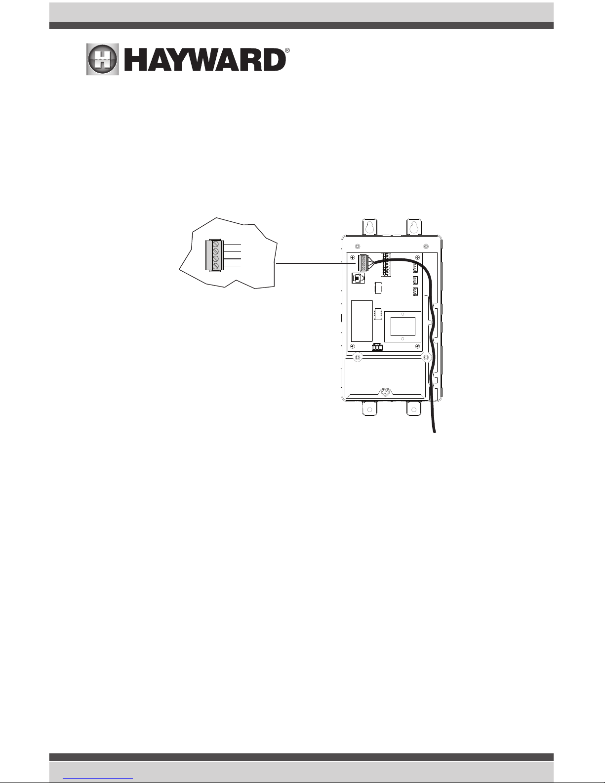
Smart Relays
Like VSPs, Smart Relays rely on communication from the Hub. Their 4 conductor cable is wired to
the same connector as a VSP. Wire the cable as shown below. Up to two Smart Relays can be controlled by the VS Omni. In addition to communication wiring, the Smart Relay will be wired to high
voltage pool equipment shown on page 13.
Valve Actuators
When wired for 230 VAC, the VS Omni can control up to two valve actuators which allow automated
control of pool/spa, water features, cleaners or solar heating. The VS Omni is compatible with standard valve actuators manufactured by Hayward, Pentair/Compool, and Jandy. Actuators have 15 ft
cables that are terminated with connectors that plug directly into the Hub as shown on page 10.
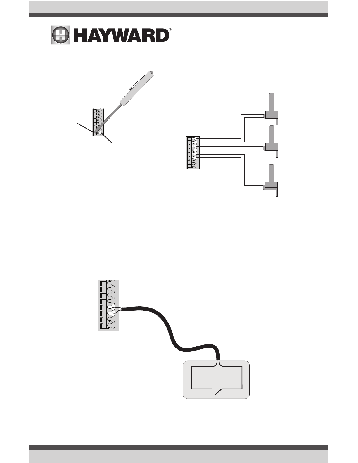
Temperature Sensors
The Hub utilizes 10K ohm thermistor type sensors with 15 ft cable. If a longer cable is required, contact the Hayward service dept. (908-355-7995) for information on suitable cable types and splices.
Temperature sensors are wired to the 8 position connector shown on page 10 and on the following page. To unlock, push on the corresponding lever with a small tool as shown. When pushed,
the connector will be open and able to receive the wire lead. For best results, strip back leads 1/8"
before inserting. After the wire is fully inserted, release the lever and the wire will lock in place.
Green
White
Black
Red
Smart Relay Connection
USE ONLY HAYWARD GENUINE REPLACEMENT PARTS
14
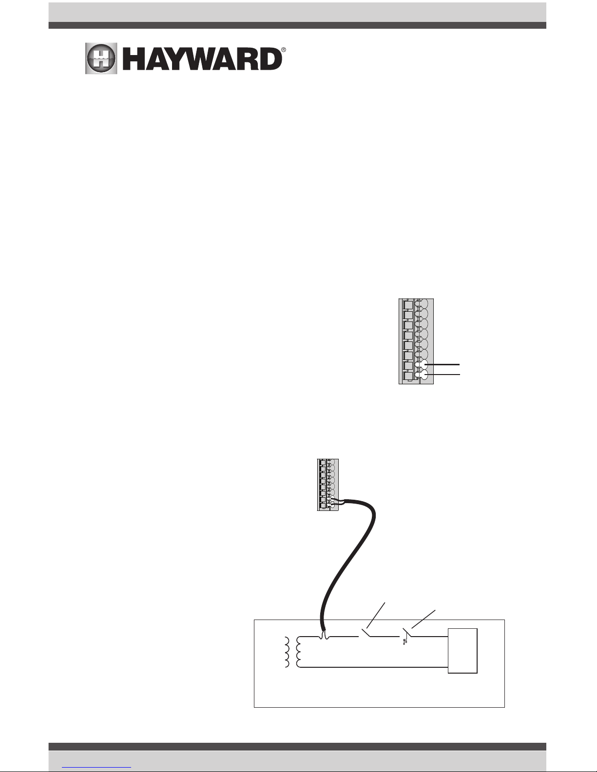
External Input Switch
If solar heating won't be used, a SPST external switch/device can be connected to this input. This
normally open or normally closed on/off external device provides a means to turn the filter pump or
other pool equipment on or off when certain conditions exists. Connect the external switch as shown
below. After properly configuring the VS Omni (see Configuration Wizard), the filter pump and/or
desired pool equipment will be forced on or off when the external device is activated.
SPST External Switch
Either Normally Open or Normally Closed
Push on lever
Insert wire here
Pool/Spa Sensor
Air
Sensor
Optional Solar Sensor or
External Input Switch
15
USE ONLY HAYWARD GENUINE REPLACEMENT PARTS
Control Pad
The Control Pad has a 15 ft cable with a connector that plugs directly into the Hub as shown on
page 10.
Note that there are rubber plugs covering USB port and Ethernet port on the bottom of the Control
Pad. The ethernet port is available for those that desire a wired connection to their access point,
rather than using the VS Omni's built-in wifi (see page 21). The USB port is only used for firmware
upgrades.
Optional Flow Switch
The 15 ft flow switch cable plugs into the flow switch connector shown on page 10. Ensure that the
connector catch “snaps” in order to provide a reliable connection.
Heater
Ignition/Valve
Heater
Kill Switch
Thermostat
Heaters
The manuals supplied with most heaters also include specific wiring
instructions for connecting the heater to an external control (usually
identified as “2-wire” remote control). For millivolt or line voltage
heaters, contact Hayward Tech support, 908-355-7995. Refer to
the information on the following pages for more details on the connection to several popular heaters. Refer to the diagram below for
the location of heater connections at the Hub.
Generic Heaters
1. Wire heater to 115/230V power source per the instructions in the heater manual. The Hub
does NOT control the power going to the
heater.
2. Wire the Hub dry contact heater output
per the diagram below. Many internal
parts of the heater can get very hot--see
the heater manufacturer’s recommendations on the minimum temperature
rating for wires. If no guidance is given,
use 105°C rated wire.
3. Set any ON/OFF switch on the heater to
ON.
4. Set the thermostat(s) on the heater to
the maximum (hottest) setting.
USE ONLY HAYWARD GENUINE REPLACEMENT PARTS
16
 Loading...