

OWNER’S MANUAL
Installation, Operation and Service
HEAT PUMP STYLE
POOL / SPA
HEATERS
TA2267
Jan. 2004

Owner’s
Manual
I. Operating Principles
• How a heat pump works…………...………………………………………………….2
• Get familiar with your heat pump ………………………………………………...….3
Temperature control systems for each model……………………….………...……4-9
•
II. Installation Specifications and Procedures
•
eceipt inspection of unit……………………………………………………...……10
R
• Determining optimum location…………………………………………………..….10
Clearance…………………………………………………………….………….11
o
o
Placement………………………………………………………………………..11
o
Drainage…………………………………………………………………………11
Other Precautions………………………………………………………………..12
o
III. Application Guidelines and Maintenance
• Climate Conditions……………………………………………………...……….…..12
• Pool Cleaning Systems………………………………………………………………12
• Efficient Practices
o
Using a pool cover…………………………………………..…………………..13
Water flow………………………………………………………………………13
o
o
Chlorine content…………………………………………………………………13
• Cleaning Procedures………………………………………………………..………..14
• At the beginning of each season………………………………………….………….14
• Occasional / Weekend Use…………………………………………….…………….15
• Summertime Shutdown…………………………………………….………………..15
At the end of each season………………………………………...………………….15
•
IV. Service Procedures
• Before you call for service……………………………………………..………..16, 38
Troubleshooting guide…………………………………………………………...16-18
•
V.
Warranty
……….……………………..……………………………….………...19
VI. Installation Guide
……………………………………………………...…20-40
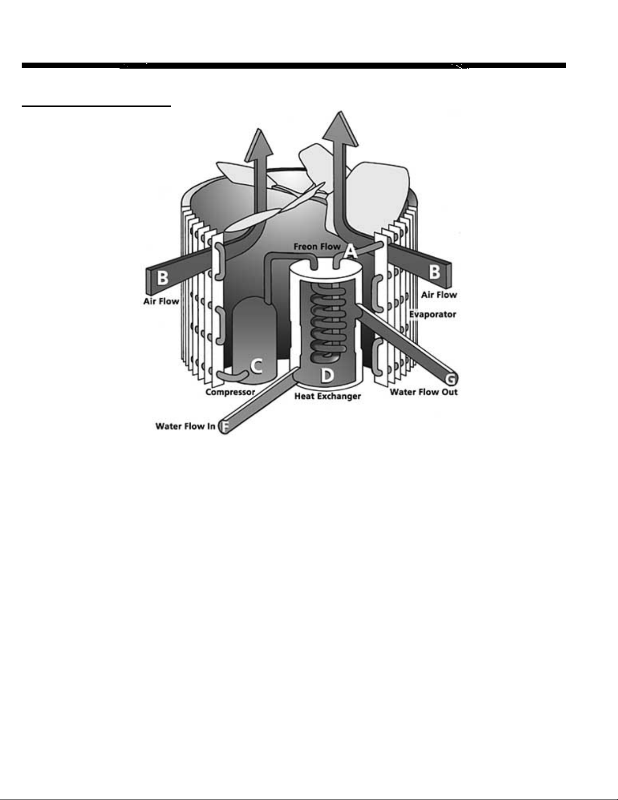
How a Heat Pump Works
Hayward Heat Pumps take heat from the environment and use it to heat your pool
water. During heat pump operation, liquid freon from inside the unit is pumped
through the system (A) and is turned into a heated gas. This happens when heat is
taken from the surrounding air (B) as it is drawn through the evaporator by the fan.
The compressor (C) receives this warmer gas and compresses it to a higher
pressure, resulting in the freon reaching even higher temperatures. As the unit
sends the heated gas through the heat exchanger, the gas gives up its heat to the
surrounding water (D). The freon reverts to a liquid state as it gives up the heat to
the pool water, which completes the cycle (A). The water (F), which is being
forced through the heat exchanger (D) by your pool pump, is heated by three to
five degrees as it passes through and returned to your pool as heated water. (G)
This process can also be reversed to remove heat from pool water.
A heat pump can transform 4 to 6 units of heat energy (BTU’s) for every 1
equivalent unit of electrical energy it consumes. This results in a coefficient of
performance between 4 and 6. The specific performance coefficient depends on
your heater model, ambient air temperature and climatic conditions, as well as
incoming pool water temperatures.
2

Get Familiar with Your Heat Pump
Safety Features
Hayward heat pumps are equipped with safeguards that will stop operation to protect your unit in case
of the following events:
High / Low Refrigerant Pressure Switches
• The high-pressure switch senses the refrigerant pressure in the sealed refrigeration system
and shuts the heater down in the event unsafe operating pressures are reached. The heat pump
will automatically reset after the system pressure drops back to normal operating pressures. When
this switch is tripped, digital displays will read “HP”
• The low-pressure switch senses the refrigerant pressure in the sealed refrigeration system to
protect against certain conditions that could be detrimental to compressor life. The switch shuts
the unit down in the event of loss of refrigerant, fan motor failure, evaporator freeze-up and
airflow blockage. The switch automatically resets when the pressure rises to normal operating
pressures. The display will show “LP” if this switch is tripped.
Heat Pump Pool / Spa Heater Owner’s Manual
• Excessively high refrigerant pressure
• Excessively high water temperature
• Loss of refrigerant
• Fan Motor Failure
• Evaporator Freeze-up
• Low Ambient Temperature
Refrigerant line blockage or overcharging
•
Evaporator Freezing
The low-pressure switch will shut the heat pump down when the evaporator starts to freeze.
When the unit starts to freeze the low-pressure switch will be tripped, causing the display to read
“LP” This will prevent the evaporator from becoming damaged or deformed.
Water Pressure Switch
The water pressure switch contacts close when pressure is applied as pool water flows through
the heat exchanger. Low flow rates as well as no flow will let these contacts open and this will
cause the unit to shut down. The display will read “PS” if the water pressure is not sufficient.
Time Delay
All models use a 5-minute time delay to prevent repeated tripping of the compressor thermal
overload, which is caused by attempting startup before system pressures are equalized. Any
interruptions, outside of power loss, will result in a 5-minute time delay.
Low Ambient Temperature
If the air outside the heat pump is not warm enough to produce heat, the system will shut down.
The actual point at which your unit will shut down due to low temperature varies depending on
which model you purchased, current weather conditions, and the amount of sunlight reaching the
heat pump. The shutdown can occur anywhere within a wide range of temperatures, usually
45≡F-55≡F. This is not a “fixed” range. We stress that climate conditions, sunlight, and various
models respond quite differently to low ambient temperature. A shutdown occurs because low
temperatures will activate the systems low-pressure safeguard switch (digital thermostats will
display a code “LP”.) The unit will start up again when the temperature has raised enough to reset
this switch. Note: Low ambient temperature does not necessarily affect the Chiller models
or the cooling cycle of the heat/cool units.
3
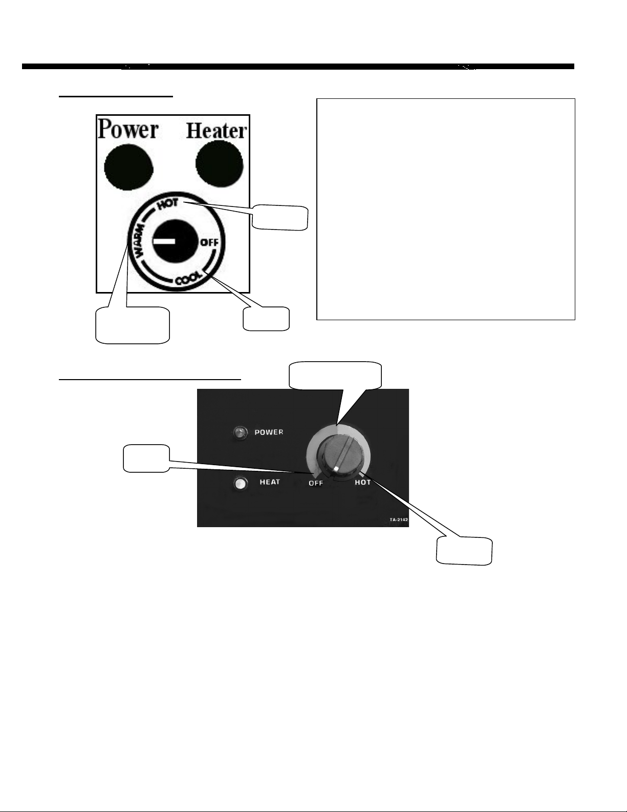
Analog Thermostat
Approx.
83°F
105°F
60°F
Power Indicator Light: Shows that proper power is
supplied.
Heater Indicator Light: Shows the unit is operating
normally and the thermostat is making a demand for
heat.
Temperature Control Knob: Adjust knob to desired
range, using the diagram on the left as a guide. The
thermostat has a temperature range from 60°F –
105°F(approx. ± 5° at the mid point.) Once you have
the dial is set to the preferred temperature, the unit
will achieve and maintain this temperature.
For help with this type of control, refer to the
troubleshooting guide
.
Single Mechanical Thermostat
60°F
Power Indicator Light: Shows that power is supplied.
Approx. 83°F
105°F
Heat Indicator Light: Shows the unit is operating normally and the thermostat is making a demand for heat.
Temperature Control Knob: Adjust knob to desired range, using the diagram above as a guide. The
thermostat has a temperature range from 60°F – 105°F. Once the dial is set to a preferred temperature, the
unit will achieve and maintain this temperature.
** The Single Mechanical Thermostat models do not turn off under 60 degrees F. This model was designed
to come on automatically if your water temperature is below 60 degrees to prevent the pool from becoming
excessively cool and creating long recovery times. If your application dictates the need to turn the heater off
for extended periods of time, use the circuit breaker.
For help with this type of control, refer to
Control
in the back of the owner’s manual.
Troubleshooting Guide for
MECHANICAL
Thermostat
4
Heat Pump Pool / Spa Heater Owner’s Manual
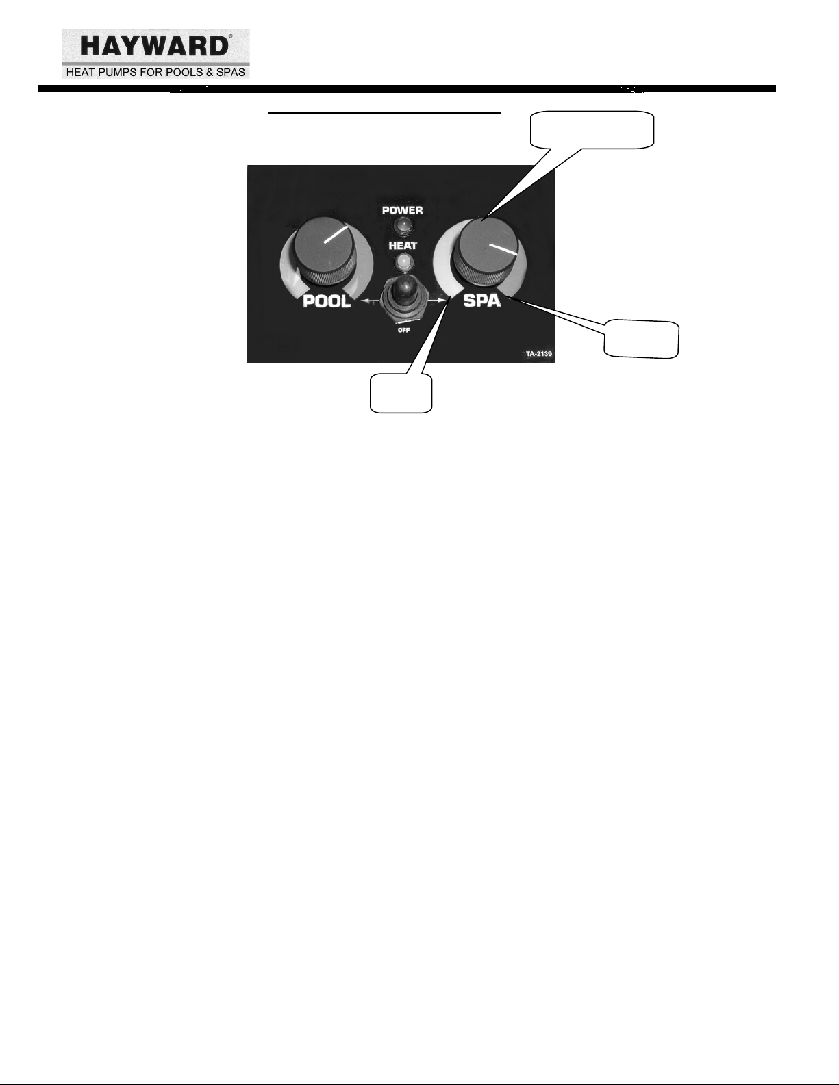
Dual Mechanical Thermostat
60°F
Power Indicator Light: Shows that power is supplied.
Approx. 83°F
105°F
Heat Indicator Light: Shows that the unit is operating normally and the thermostat is making a
demand for heat.
Temperature Control: Adjust knob pool or spa to desired range, using the diagram
above as a guide. The thermostat has a temperature range
from 60°F – 105°F. Once the dial is set to a preferred
temperature, the unit will achieve and maintain this
temperature.
Mode Toggle Switch: Off: Middle position, sets the unit to a “no-heating” mode.
Pool: Flip the switch toward the pool control knob (left). This sets the
unit into pool mode. The unit will maintain the preferred
temperature set point for your pool.
Spa: Flip the toggle switch toward the spa control knob (right). The unit
will maintain the preferred temperature set point for your spa.
For help with this type of control, refer to Troubleshooting Guide for MECHANICAL
Thermostat Control in the back of the owner’s manual.
5
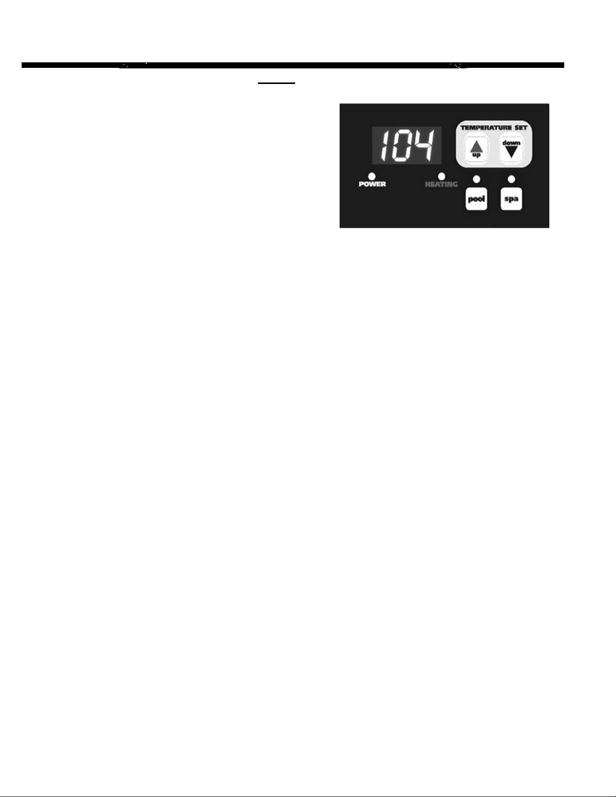
PST-1
Power Indicator Light: Indicates that power is
supplied to the heat pump
but does not indicate that
the unit is in operation.
Heating Indicator Light: Shows the unit is operating
normally and the thermostat
is making a demand for
heat.
Display: When power is supplied to
the unit, the display will
either show temperature,
diagnostic code (such as “PS”), or rolling dots.
On/Off: This control does not have a true on/off feature. The unit uses standby mode
instead. Rolling dots in the display indicate standby. Standby mode serves two
functions. (1) It serves as an “off” mode, which keeps the heat pump from
transferring heat into your pool water. (2) Standby allows a pool owner with
remote controlling systems, such as Jandy or ComPool, to maintain pool and
spa temperatures via their remote.
To enter standby mode: If pool mode is active (indicated by the green led over the pool button), press
the pool button once. Rolling dots should appear on the display.
If spa mode is active (indicated by the green led over the spa button), press the
spa button once. Rolling dots should appear on the display.
To exit standby mode: Press either the pool or spa mode button.
Mode Selection: Selecting the desired mode of operation (spa or pool) is accomplished using the
POOL / SPA buttons. A green LED above buttons designates the active mode.
When the pool mode is active, any displays or adjustments apply only to the
pool mode. Adjustments for spa mode must be made while the spa button is
activated. A user can switch between modes without turning the control to
standby first.
Temperature
Setpoint: Pool mode range is 70-98°F (21-37°C).
Spa mode range is 70-105°F (21- 41°C).
Adjust the setpoint: Continuing to hold the up or down button will scroll the setpoint value until
the desired setpoint is reached. When the desired value has been reached, release the button. The
new setpoint will flash to indicate a new value has been recognized and the display will revert
back to water temperature as indicated by a steady display.
Note
: The temperature reading displayed when the unit is in operation (heating indicator light is present)
displays the current water temperature.
To display the setpoint
setpoint for 3 seconds.
: Press and release the Temperature Set up or down button once will display the current
For help troubleshooting this type of control, refer to the Troubleshooting
Guide for
DIGITAL Thermostat Control in the back of this manual.
6
Heat Pump Pool / Spa Heater Owner’s Manual
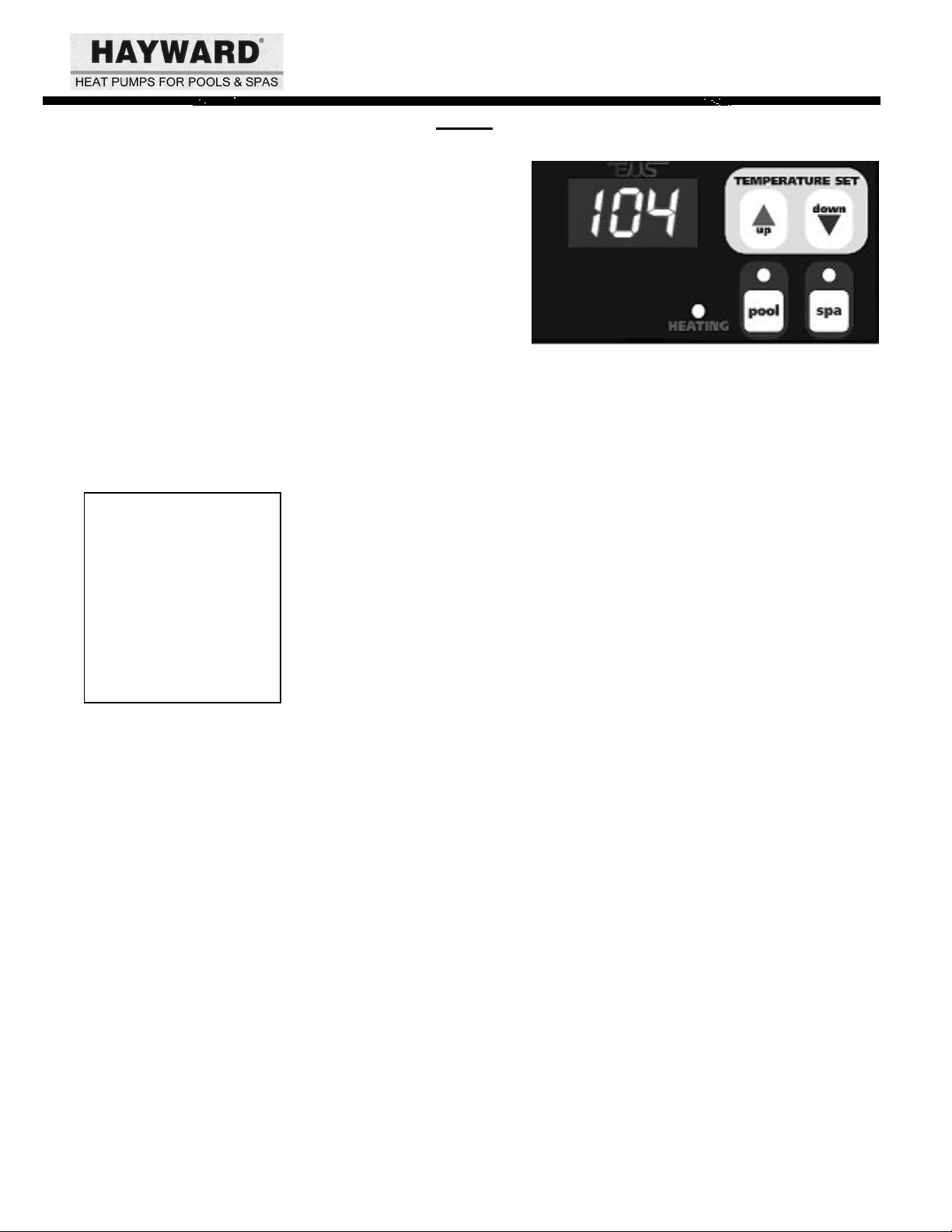
PST-4
The PST-4 temperature control is similar to the PST-1
shown above, with two differences. (1) The PST-4 has
a Time Clock Override. (2) The PST-4 has no power
indicator light.
Please read the data for the PST-1 on the previous page before continuing. It will provide you with
descriptions of button functions and setpoint programming.
Time Clock Override: This feature must be connected by an electrician. TCO provides a method of
maintaining the pool temperature when a time clock has the pool filter pump
turned off. TCO function then controls the pool filter pump via the PST-4.
Notes:
1. An electrician must
wire the TCO
function to your pool
system before it will
work.
2. The 2-hour TCO
checking interval
cannot be adjusted.
TCO will automatically turn the pool filter pump on after 2 hours of “off
time”. It will run the filter pump for 10 minutes while monitoring the water
temperature. If there is more than a 2-degree difference between the setpoint
and the actual pool temperature the heat pump will energize and continue to
run until the setpoint is satisfied.
A user may temporarily override the TCO. An example would be that you
want to use your pool between 9:00 and 10:00 pm. The control may be
programmed to energize the filter pump, which will engage the heat pump to
maintain the pool temperature. This is a temporary measure that can be
initiated in 30-minute increments, for a period up to 3 hours.
Programming for Temporary Pump Override:
1) Push and hold up and down buttons simultaneously – Display reads P0.0
2) Release buttons.
3)
4)
Push up button – display reads P0.5 (Each time the up Arrow engages, the
display will increase by .5 increments. Each .5 increment equals 30 minutes,
3 hours is the max.).
Push down button to decrease the temporary override time.
Example of typical TCO cycle: When the time clock turns off the filter pump, a “PS” will show on
the display. A timer starts inside the controller. After 2 hours, the heater will start the filter pump to
circulate water. “PS” is removed from the display and if a demand for more heat is made, the heater
goes back to normal operation. When the water is brought back to temperature, the TCO turns off the
filter pump and the heat pump will shut-down, displaying “PS”. The 2-hour timer is reset and the cycle
will begin anew.
For help troubleshooting this type of control, refer to the
Thermostat Control
in the back of this manual.
Troubleshooting Guide for
DIGITAL
7
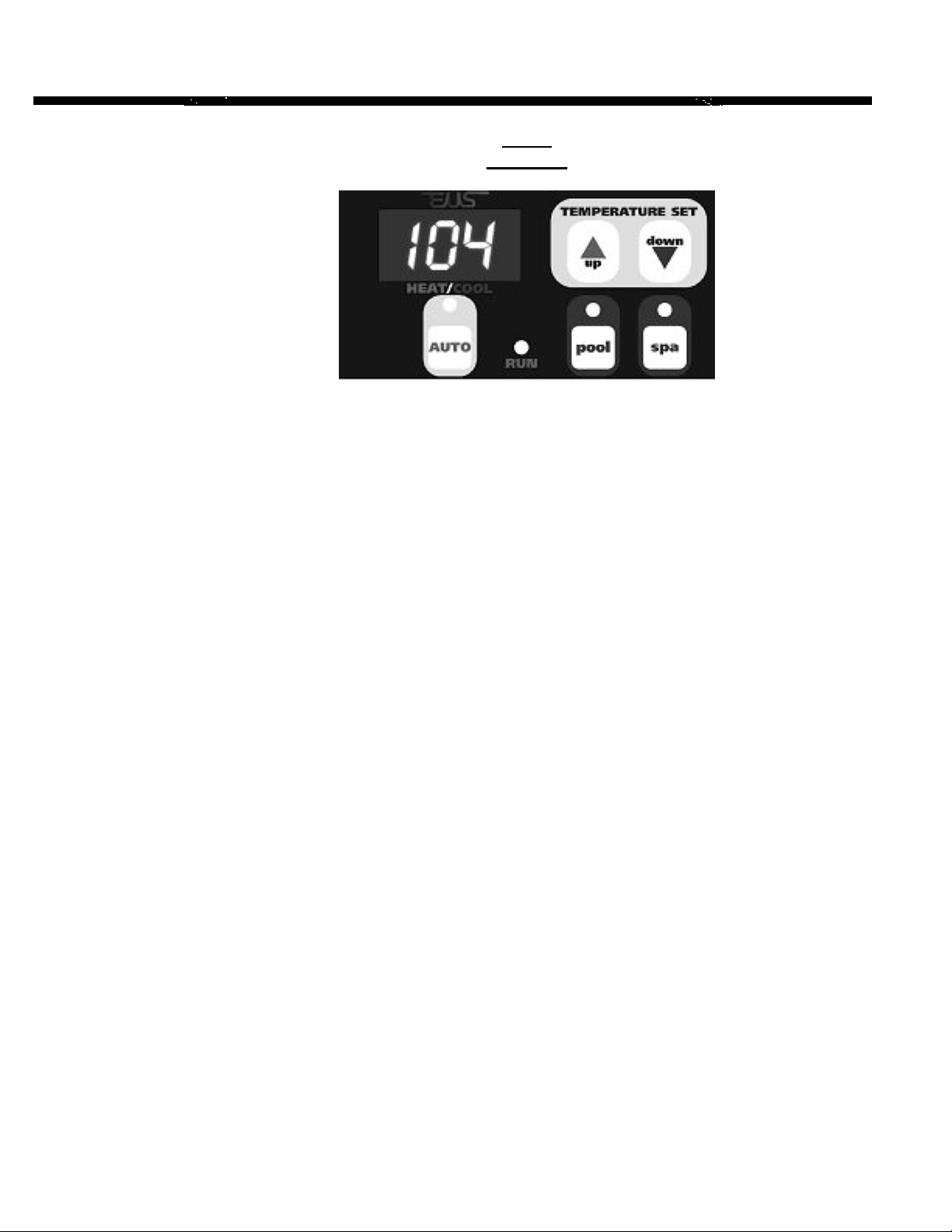
PST-5
Heat/Cool
The PST-5 is an upgrade of the PST-4 with the addition of an AUTO function. This allows the heat pump to
heat or cool the water automatically to maintain the setpoint. The PST-5 also has an optional Time Clock
Override (TCO-This feature must be connected by an electrician to operate.)
Read the instructions for the PST-1 and PST-4 fully before continuing. . The PST-1 page will
provide you with descriptions of button functions and setpoint programming. If you have purchased
the TCO option, the PST-4 page will provide TCO functionality and programming procedures.
Run indicator light:
Serves the same function as the “heating” indicator on the PST-1
and PST-4.
Setting the
AUTO function:
will be off.)
1. Disengage the AUTO mode (the AUTO mode indicator light
2. Program your desired temperature setpoint.
3. Press the AUTO button to activate the automatic heat / cool
function. (AUTO mode indicator will light.)
4. “AC5” should show on the display (set at the factory). “AC”
indicates that the cooling function is enabled and the
“5”means that when the water temperature is 5°F above the
setpoint, the unit will energize to cool your pool or spa.
By using the up and down keys, the AC5 can be changed to
values ranging from AC3 to AC9.
Setting unit to
cool only:
Engage the AUTO mode and use the up button to scroll past “AC9”. You
will notice that after the display of “AC9” an “ACP” (AUTO Cool
Primary) will be displayed. When “ACP” is displayed, the unit will only
cool the pool and will not go into the heating mode, no matter how
cool the pool gets.
NOTE: The
light will flash during cooling cycles.
RUN
Time Clock Override: Refer to TCO information on the previous page. (PST-4)
If troubleshooting this controller, refer to the
Troubleshooting Guide for DIGITAL Thermostat Control.
8

Installation Specifications
Receipt Inspection of Unit
Inspect the heat pump pool heater carton upon receipt for possible damage in shipment. Check
the “Tip-n-Tell” indicator attached to the outside of the box. A punctured or oil-soaked area of
the carton could indicate damage to the sealed refrigeration system. If damage has been
incurred or is suspected, bring it to the immediate attention of the delivering carrier. The carton
bears specific warnings stating “DO NOT DROP OR TAILGATE”, as well as arrows indicating
the correct vertical positioning. THE POOL HEATER MUST NOT BE TIPPED OR
TRANSPORTED ON ITS SIDE AS EVAPORATOR “OIL LOGGING” MAY OCCUR.
Upon arrival at the installation site, the unit should be carefully unpacked and again inspection
for any damage that may have occurred in transit. Minor indentations to the aluminum
evaporator fins will not affect performance of the unit.
THE MANUFACTURER CANNOT ACCEPT RESPONSIBILITY FOR
DAMAGE INCURRED OR REPAIRS NECESSITATED DUE TO IMPROPER
Heat Pump Pool / Spa Heater Owner’s Manual
HANDLING OF OUR EQUIPMENT.
Determining Optimum Location
THE LOCATION OF THE HEAT PUMP POOL HEATER IS VERY IMPORTANT FOR
EFFICIENT OPERATION
In order of importance, the installer must consider the following conditions:
o The heat pump will perform more efficiently when placed in direct sunlight
o Ample air intake
o Avoidance of air recirculation
o Accessibility of service panels
o Means of draining condenser in freezing weather (such as union-style fittings)
o Means of draining condenser and rainwater. Insulation of long water lines (over 25 ft.) from
heater to pool.
The installation of the unit in a fully enclosed area (i.e. garage, shed, etc.) is not
recommended. Consult HAYWARD for indoor pool application analysis.
.
.
9
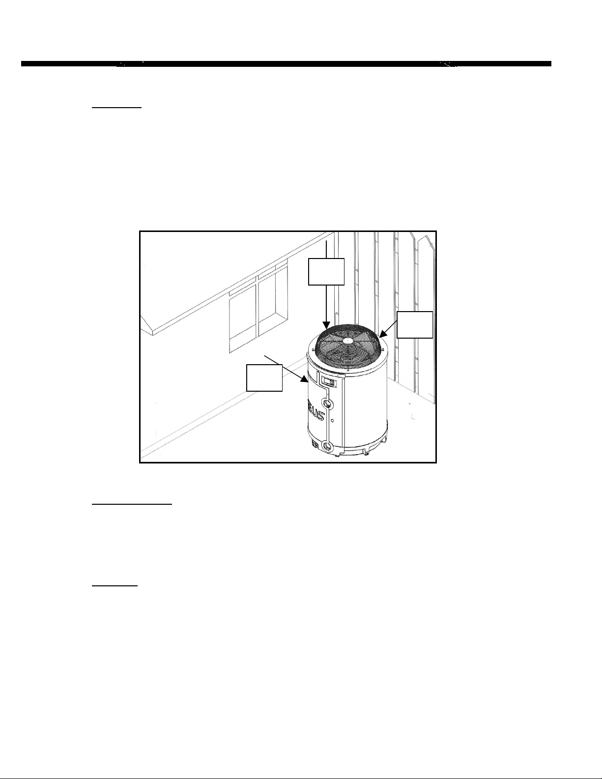
Clearance
A minimum of two feet of clearance from walls, shrubbery, equipment, etc. is required
around the entire pump circumference. This allows for ample air intake. No less than 6
feet clearance above the heat pump is required to prevent re-circulation of air. We
recommend not placing the unit underneath eaves, decks, or porches, as this causes
recirculation of discharged air.
RECIRCULATION OF DISCHARGED AIR BACK INTO THE PUMP WILL
GREATLY REDUCE ITS EFFICIENCY.
6 ft
2 ft
2 ft
Level Placement
The heater should be located on a solid, level surface. The pool heater is
exceptionally quite, but if further noise reduction is desired, the heat pump may be
placed on vibration absorbent pads, which are available from most airconditioning and refrigeration wholesalers.
Drainage
Condensation drain holes are provided in all base pans for adequate removal of
condensation and rainwater. Keep the drain holes unobstructed. Clean them
regularly (with your finger or a short stick) to remove any debris that may block
them.
HEAT PUMPS GENERATE WATER CONDENSATION DURING
NORMAL OPERATION. THIS SHOULD NOT BE MISTAKEN FOR A
LEAK IN THE UNIT.
The troubleshooting section provides recommendations should you suspect a leak.
10

Heat Pump Pool / Spa Heater Owner’s Manual
Other Precautions
The heat pump should not be placed near sprinkler systems, especially those
where fertilizer is added. This is very corrosive and, over time, will severely
damage the unit. If you live in an oceanfront area, the heat pump should be placed
out of direct spray of sand and salt. This will also clog, damage, and corrode the
unit. You may consider protecting your heat pump by planting shrubbery or a
privacy fence between the unit and the prevailing beachfront wind.
Application Guidelines and Maintenance
Climate
Weather conditions have a significant impact on pool heating. Local weather and
climate data are general conditions surrounding your pool. The microclimate
surrounding the pool must also be considered.
Lots of shade, low air temperature, relative humidity, and high wind velocity at the
pool surface negatively impact pool heating and will require an increased pool
heater output to maintain pool temperature.
Cleaning Systems
Some pools have cleaning systems attached to the filter pump intake (i.e. crawlers
and skimmers). These devices slow the flow of water entering the heat pump. As
low flow rates may damage the heat pump, built-in safeguards will automatically
shutdown the unit in instances of low water flow.
Dirty pool filters slow water flow and may cause a shutdown.
Familiarize yourself with the pool filter. Know how to check and clean or replace
it yourself. Do not completely trust a pool cleaning service to do this task for you.
11

Efficient Practices
Using A Pool Cover
POOL COVERS ARE STRONGLY RECOMMENDED.
A pool loses heat in several ways but testing shows that evaporative cooling (the cooling
effect created by water evaporating from the surface of the pool) accounts for
approximately 75% of a pool’s heat loss. However, if a pool is covered when it is not in
use, most evaporative cooling can be prevented. If the pool temperature is to be
maintained, the pool heating system must replace heat lost. Thus, the use of a pool cover
can offer dramatic savings in energy consumption. The cover’s approximate effect on
pool heat losses is illustrated in the table below:
SOURCE POOL UNCOVERED POOL COVERED
Of Heat Loss (USED 12 HRS/DAY)
Evaporative cooling 75% 30%
Convection loss to air 15% 10%
Ground loss (dry earth) (Negligible – less than 1%) (Negligible)
Re-radiation to environment 9% 9%
Make-up water 1% 1%
__________ ________________ ________________
Total 100% 50% of uncovered
pool losses
As the table shows, a pool cover that prevents evaporative cooling can reduce the
heat loss from a pool approximately 50% (which also cuts your power
consumption by 50%.)
Water Flow
To minimize heating times, make sure all water valves are open completely, that
the water level of the pool is at the correct height, and that any fountains or
waterfalls are disconnected or turned off. Maintain 30–75 gpm flow rate.
CHECK YOUR PUMP FILTER WEEKLY. REPLACE OR CLEAN AS
NECESSARY TO ENSURE PROPER FLOW RATES.
Chlorine Content
Chlorine is corrosive, along with other chemicals used in sanitizing pools.
Improperly maintained pH alkalinity levels are unhealthy for you and your pool
systems. Maintaining proper water pH levels will increase the life of all your pool
components, including your heat pump.
installed downstream of the heat pump (in the return line to the pool) and a check valve
installed in a manner that will not allow the raw chlorine to drain back to the heat pump
when the water pump is off. Do not allow pool maintenance people to pour chemicals
in skimmer.
Automatic chlorinators, if used, must be
12
 Loading...