

Page 1
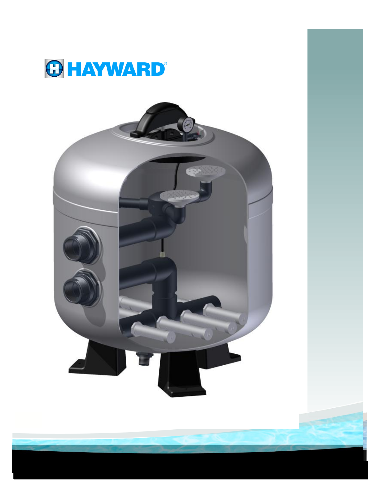
COMMERCIAL SAND FILTER MANUAL
Models: HCF302 / HCF362 / HCF363
Models :
HCF302T, HCF342T, HCF343T, HCF343F, HCF362T, HCF363T, HCF363F
LITCF301
Page 2
2
Table of Contents
1. Important Safety Instructions
2. General
2.1 Swimming Pool Filters
2.2 Hayward® Filters
2.3 Selection of Filters and Installation
2.3.1 Filter Characteristics
2.3.2 Installation Characteristics
2.3.3 Piping Connection Kits
3. Characteristics and Dimensions
3.1 Dimensions
4. Installation
4.1 General Installation Notes
4.2 Filter Installation
4.3 Installation of the Pressure Gauge
4.4 Removing the Filter Manway Cover
4.5 Re-Installation of the Manway Cover
4.6 Testing of Filter
4.7 Installation of the Sand
5. Normal Operation
5.1 Filtration
5.2 Backwash
5.3 Close/ Isolate
6. Changing of the Sand
7. Winterizing
8. Graph of Filter Head Loss
9. Replacement Filter Parts List
10. Warranty
11. Product Registration
12. Warranty Card Registration
Commercial Sand Filter
Models: HCF302T, HCF342T, HCF343T,
HCF343F, HCF362T, HCF363T, HCF363F
Page 3
3
1. Important Safety Instructions
Basic safety precautions should always be followed, including the following: Failure to follow
instructions may result in injury.
This is the safety-alert symbol. When you see this symbol on your pump or in this manual, look
for one of the following signal words, and be alert to the potential for personal injury.
WARNING warns about hazard that could cause serious personal injury, death or major
property damage if ignored presents a potential hazard.
CAUTION warns about hazards that will or can cause minor or moderate personal injury and/or
property damage and if ignored presents a potential hazard. It can also make consumers aware of
actions that are unpredictable and unsafe.
The NOTICE label indicated special instructions that are important but not related to hazards.
WARNING – Read and follow all instructions in this owner’s manual and on the
equipment. Failure to follow instructions can cause severe injury and/ or death.
WARNING – This product should be installed and serviced only by qualified professionals.
CAUTION – All electrical wiring MUST be in conformance with all applicable local codes,
regulations, and the National Electrical Code (NEC).
WARNING – To reduce risk of injury, do not permit children to use or climb on this product.
Closely supervise children at all times. Components such as the filtration system, pumps, and
heaters must be positioned to prevent children from using them as a means of access to the pool.
WARNING – Pool and spa components have a finite life. All components should be inspected
frequently and replaced at least every seven years, or if found to be damaged, broken, cracked,
missing, or not securely attached.
WARNING – Suction Entrapment Hazard. Suction in suction outlets and/ or suction outlet
covers, which are damaged, broken, cracked, missing, or unsecured cause severe injury and/ or
death due to the following entrapment hazards (symbols compliments of APSP):
Hair Entrapment – Hair can become entangled in suction outlet cover.
Page 4
4
Limb Entrapment – A limb inserted into an opening of suction outlet sump or suction outlet cover
that is damaged, broken, cracked, missing, or not securely attached can result in mechanical bind or
swelling of the limb.
Body Suction Entrapment – A differential pressure applied to a large portion of the body or
limbs can result in an entrapment.
Evisceration/ Disembowelment – A negative pressure applied directly to the intestines
through an unprotected suction outlet sump or suction outlet cover which is damaged, broken,
cracked, missing, or unsecured can result in evisceration/ disembowelment.
Mechanical Entrapment – There is potential for jewelry, swimsuits, hair decorations, fingers,
toes, or knuckles to be caught in an opening of a suction outlet cover resulting in mechanical
entrapment.
WARNING – To Reduce the Risk of Entrapment Hazards:
When outlets are small enough to be blocked by a person, a minimum of two functioning
suction outlets per pump must be installed. Suction outlets in the same plane (i.e. floor or
wall), must be installed a minimum of three feet (3’) (.91 meter) apart, as measured from near
point to near point.
Dual suction fittings shall be placed in such locations and distances to avoid “dual blockage”
by a user.
Dual suction fittings shall not be located on seating areas or on the backrest for such seating
areas.
The maximum system flow rate shall not exceed the values shown in the “Pipe Sizing Chart”
found on page 12.
Never use pool or spa if any suction outlet component is damaged, broken, cracked, missing,
or not securely attached.
Replace damaged, broken, cracked, or not securely attached suction outlet components
immediately.
In addition to two or more suction outlets per pump installed in accordance with latest APSP
standards and CPSC guidelines, follow all national, state, and local codes applicable.
Installation of a vacuum release or vent system, which relieves entrapping suction, is
recommended.
WARNING – Hazardous Pressure. Pool and spa water circulation systems operate under
hazardous pressure during start-up, normal operation, and after pump shut-off. Stand clear of
circulation system equipment during pump start-up. Failure to follow safety and operation
instructions could cause property damage, severe personal injury, or death. Before servicing pool
and spa water circulation system, all system and pump controls must be in off position and filter
manual air relief valve must be in open position. Before starting system pump, all system valves
must be set in a position to allow system water to return back to the pool. Do not change filter control
valve position while system pump is running. Before starting system pump, fully open filter manual
air relief valve. Do not close filter manual air relief valve until a steady stream of water (not air or air
and water mix) is discharged from the valve. All suction and discharge valves MUST be OPEN when
Page 5
5
starting the circulation system. Failure to do so could result in severe personal injury and/ or
damage.
WARNING – Separation Hazard. Failure to follow safety and operation instructions could
result in violent separation of pump components. Strainer cover must be properly secured to pump
housing. Before servicing pool and spa circulation system, all system and pump controls must be in
off position and filter manual air relief must be in open position. Do not operate pool and spa
circulation system if a system component is not assembled properly, damaged, or missing. Do not
operate pool and spa circulation system unless manway cover is in seated position in filter body. All
suction and discharge valves MUST be OPEN when starting the circulation system. Failure to do so
could result in severe personal injury and/ or property damage.
WARNING – Never operate or test the circulation system at more than 50 PSI maximum.
WARNING – Failure to install according to defined instructions may result in severe personal injury
or death.
WARNING – ELECTROCUTION HAZARD. High voltage electricity is present in the pool and
spa equipment. High voltage electricity can cause shock and electrocution. Shock and electrocution
can result in severe personal injury or death.
All electrical wiring MUST be in conformance with applicable local codes, regulations and the
National Electrical Code (NEC).
Before performing any service or maintenance on electrical equipment turn off all electrical
power.
Contact a licensed electrician or building inspector for information on local electrical codes for
bonding requirements.
Verify water discharge from the filter manual air relief valve is directed away from electrical
devices.
Do not locate pump controls over or near filter.
Page 6
6
2. General
NOTICE – Each country (possibly each state) will have its own standards for public and
private pools. It is the responsibility of the installer to be aware of these codes before designing,
specifying or installing any piece of equipment for a swimming pool.
2.1 Swimming Pool Filters
Filters are, without a doubt, the most important
accessory used in the treatment of swimming
pool water. Their purpose is to eliminate
suspended particles from the circulating water,
thus clarity of the water.
The principle operation consists of passing the
swimming pool water through a bed of sand
which will retain any particles that are
suspended in the water.
It should be kept in mind that the filtration
system consists of a number of elements, such
as metering equipment, pumps, pool shell
fittings and pipe work, which ensure the correct
suction and return flows that will affect the
resultant condition of the treated water.
The quality of filtration depends on various
factors, the size and shape of the sand, the
sand bed depth, characteristics of the sand such as granular size, density, etc. A most important
parameter is the water filtration rate. Other factors affecting the selection of a filter are the materials
used for its construction, the working temperature, and the operating pressure.
2.2 Hayward® Filters
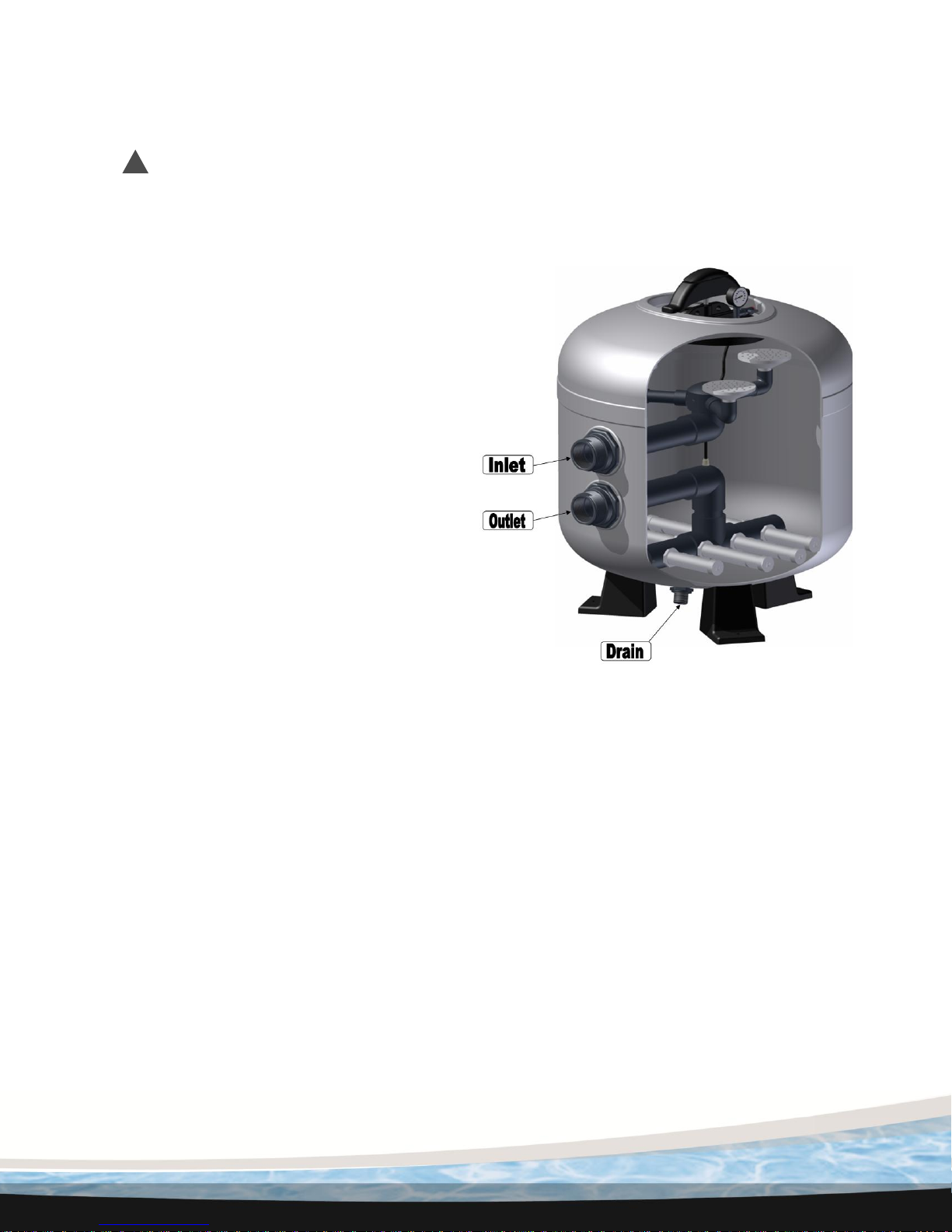
Manufactured from proprietary resins and fiberglass, they are virtually corrosion-proof. The internal
fittings (diffuser and lateral system) are manufactured from PVC and ABS. They are unaffected by
salt water and are manufactured for a working pressure up to 50 PSI and a maximum working
temperature of 122° F.
2.3 Selection of Filters and Installation
2.3.1 Filter Characteristics
Choose the filter or filters that meet the local turnover time requirements. Remember it is
possible to add filters together to obtain the correct amount of filtration area required.
Note: when using multiple filters, they must be plumbed in parallel configuration. It is also
a good idea to oversize the surface area required by 10% or more, this will allow for
better water quality. When possible, use more than one filter in conjunction, this will
allow one filter to be serviced while one is still functioning.
Page 7
7
Hayward Recommended Filter Piping Connections:
Filter Model:
Port Size
Multi-Port Valve
Piping Kit
Flange P/N
HCF302T
2”
HCV275
W/ Valve
N/A
HCF342T
2”
HCV275
W/ Valve
N/A
HCF343T
3”
HCV375
HCV375KIT
N/A
HCF343F
3”
N/A
N/A
HCF375KIT
HCF362T
2”
HCV275
W/ Valve
N/A
HCF363T
3”
HCV375
HCV375KIT
N/A
HCF363F
3”
N/A
N/A
HCF375KIT
When sizing the plumbing for a filtration package be sure to keep in mind that the
velocity of the water in the pipes is very important. Each country or state may have
different maximums for velocity in the plumbing. The recommendations of APSP-7
should be followed.
2.3.2 Installation Characteristics
To insure selection of the correct pump size, the required flow must be obtained by
taking the system head into consideration. The system head is the added difficulty to
move water through the system presented by using, elbows, piping, tees, changes in
elevation, etc.
It is also recommended that the discharge from each pump is brought together in a
single manifold to the filters. This will allow for greater flow rates for the backwash cycle.
Install a check valve ahead of filter inlet to prevent contaminants from draining
back into the pool.
Install a check valve between filter and heater to prevent hot water from backing
up into filter and damaging internal components.
Disposal of “waste water” must meet local, state and national codes.
See Chart on Page 7 for vertical and horizontal clearance.
2.3.3 Piping Connection Kits
Page 8
8
3. Characteristics and Dimensions
Filter
Model
Number
Dimensions (Inches)
Filter Area
Max Flow
Rate
Filter
Sand
Qty
(Lbs)
Clearance (Inches)
A B C D E
Sq. Ft.
Sq. M
GPM
LPM
Vertical
Horizontal
HCF302T
16.5
24.0
30.63
42.5 2 4.9
.46
98
371
650
42.5
30.0
HCF342T
18.75
26.25
34.5
47.5 2 6.3
.59
126
477
950
47.5
34.0
HCF343T
18.75
26.25
34.5
47.5 3 6.3
.59
126
477
950
47.5
34.0
HCF343F
18.5
26.22
34.5
47.5 3 6.3
.59
126
477
950
47.5
34.0
HCF362T
18.75
26.25
37.0
48.5 2 7.16
.67
143.2
542
1050
48.5
36.25
HCF363T
18.75
26.25
37.0
48.5 3 7.16
.67
143.2
542
1050
48.5
36.25
HCF363F
18.5
26.22
37.0
48.5 3 7.16
.67
143.2
542
1050
48.5
36.25
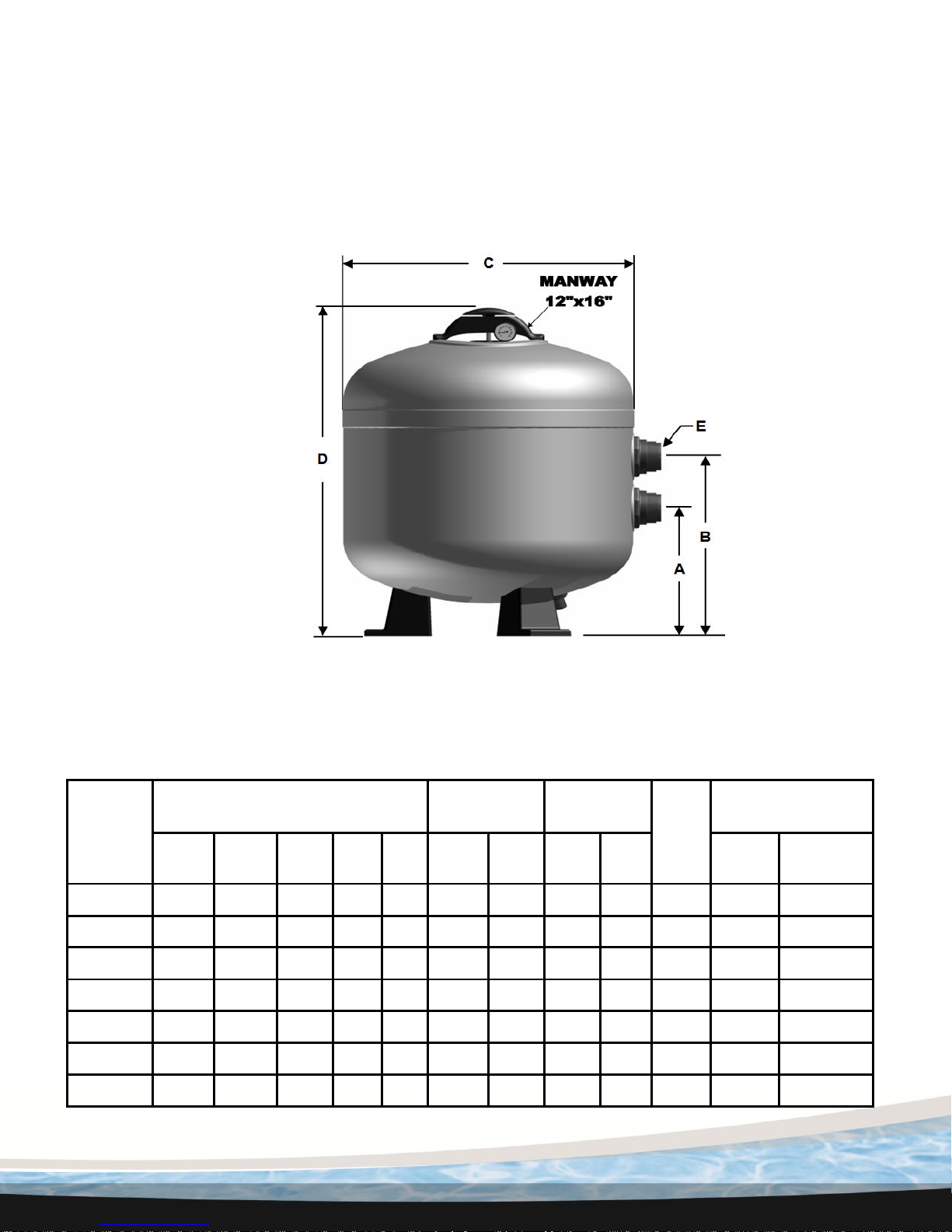
3.1 Dimensions and Sand Requirements
Use only High Rate Sand No. 20 Silica Sand (.45mm - .55mm)
Figure 3-1
Page 9
9
4. Installation
WARNING – Read and follow all Instructions.
4.1 General Installation Notes
WARNING – This product should be installed and serviced only by a qualified
professional.
Note: Filters are supplied in a box and on a pallet with accessories included. Due to their
weight and size it is recommended that mechanical means be employed to move the filter into
position. It is also very important to inspect the filters carefully before installing. Make note on
the shipping paperwork if there is any damage to the packaging. FRP filters can be damaged
during transportation and it is the responsibility of the installer to inspect at the time of delivery.
Damages to filters from transportation that are not noted on the bill of lading are not covered
by Hayward’s warranty policy and all costs to repair will be the responsibility of the owner.
Never put the sand into the filter until it is in its final working position and all prior steps are
complete.
The filter should be accessible for periodic maintenance or media change. It is absolutely
necessary to leave a minimum access space around the filter(s), as defined on page 7.
The equipment room should be well ventilated an provided with adequate drainage capabilities
so that should an emergency occur, resulting in flooding from a pipe, filter or pump, the water
can be easily removed to avoid property damage. If drainage cannot be supplied directly from
the equipment room, consideration should be given to the installation of alternate system to
remove water from the mechanical room, per federal, state and local codes.
4.2 Filter Installation
Move the filter(s) into place using whatever means available. Do not use the manway cover or
opening to maneuver the filter. Be sure to use care if moving by hand. Before continuing, be
sure that the filter(s) are in the desired location with the connections facing the direction
necessary for proper installation. It is also very important to make sure that the filter is sitting
on a level, hard surface.
It is possible that during transportation, some internal components have loosened. It will be
necessary to remove the filter manway cover and enter the filter, being careful not to break any
of the connections. By hand, check the tightness of all the laterals in the bottom of the filter
making sure they are firmly tightened.
Page 10

10
4.2.1 Tank Positioning
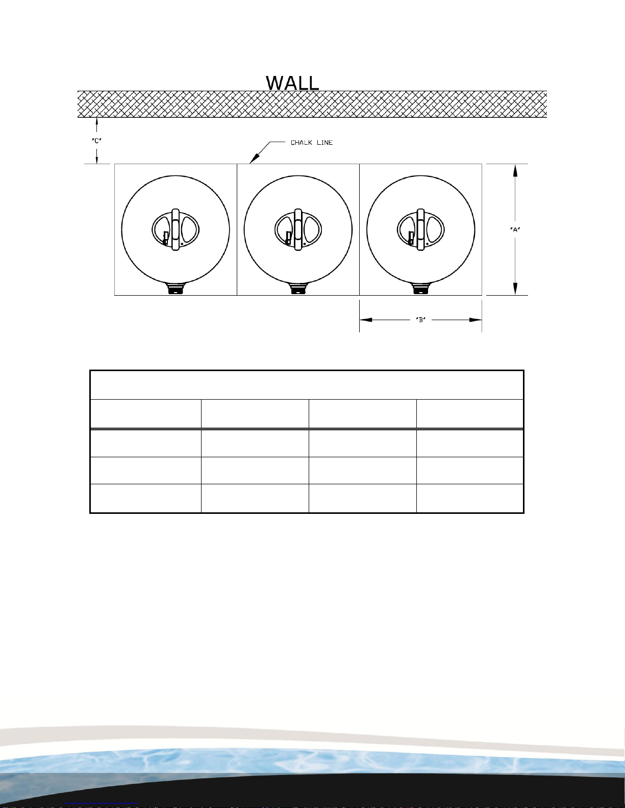
Chalk lines are recommended for multiple tank installations and should be laid for positioning
each tank. The shipping pallet for the filter also serves as an anchor bolt hole template(s) to
aid in positioning the filter tank(s).
Attention must be paid to the location and routing of the influent, effluent and waste line
plumbing when planning the proper location of the filter system. The tanks must be level and
parallel to each other or damage may occur to filter tanks, operating valves or connecting
piping.
Anchor bolts, nuts and flat washers can be purchased. Anchor bolts must be installed and
secured to comply with the requirement of specific seismic zones. If the filter room floor is not
level, shims must be used to level the tanks or the face piping plumbing connections may
break or leak.
Select one of the following appropriate assembly steps for your filter system:
4.2.1.1 Positioning Single Tank
Position the tank in the desired location, drill anchor bolt holes, and install anchor bolts,
washers and nuts. Tighten nuts to secure filter system.
4.2.1.2 Positioning Multiple Tanks
Position the tank positioning templates along the chalk line. The templates, when butted
together side by side, will ensure the proper alignment of filter tank to filter tank and tanks to
face piping.
The pallet template footprint is 6” larger than the filter tank. If you are positioning the rear of the
filter tank six (6”) inches away from the mechanical room wall, you must set the templates at
the “C” dimension for proper anchor/ tank location (see figure 4-1).
Page 11
11
Anchor Template Dimensions
Filter Model:
A B C
HCF30
39”
36”
6”
HCF34
42”
40”
6”
HCF36
45”
42”
6”
Figure 4-1
Position first tank, installing all anchor bolts and secure before positioning the next
tank and so on.
Page 12
12
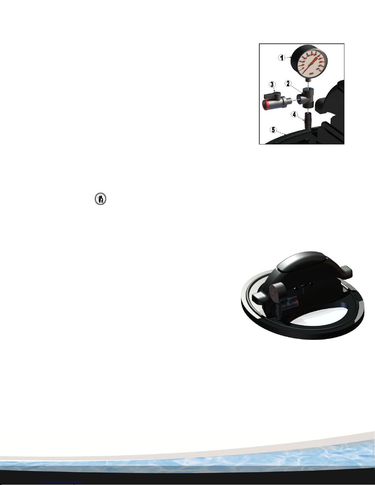
4.3 Installation of the Pressure Gauge
The pressure gauge assembly will come in a bag hanging from a
diffuser within the filter. Remove all the parts from the bag and apply
Teflon tape to all threaded connections. Thread the pressure gauge
(1) into gauge tee (2). Screw vent valve (3) into other side of the
gauge tee (2). Thread long nipple (4) into gauge tee (2) and into
manway cover (5).
Once the system is started, open vent valve (3) to bleed any air that
might have been trapped in the filter during startup.
1- Pressure Gauge 2 – Gauge Tee 3 –Vent Valve
4 – PVC Long Nipple 5 – Manway Cover
4.4 Removing the Manway Cover
WARNING This product should be installed and serviced only by a qualified pool
professional. Your filter comes with a filter manway cover pre-installed from the factory.
For qualified pool professionals only: If filter manway cover needs to be serviced, follow these
instructions carefully.
1. Turn off all system circulation pumps and all electrical
power in the equipment controls.
2. Set all system valves in a position to prevent water from
flowing to the filter.
3. The manual air bleed valve (vent valve) must be placed in
the OPEN position.
4. Wait until all water leakage has stopped.
5. While holding the manway cover by the finger holes, rotate
the knob portion of the manway cover yoke counterclockwise
until released from the manway cover.
6. Push the manway cover into the filter tank, rotate cover.
7. Remove the manway cover from the tank, a slight rocking
motion may be required to clear the internal piping in the filter
tank
4.5 Re-installation of the Manway Cover
1. Check the seals, replace as needed.
2. With a clean cloth, wipe upper filter body manway seat. Remove all dirt and debris.
3. Insert the manway cover into the filter tank, hold the manway cover by the finger holes.
4. Rotate the manway cover into position, a slight rocking motion may be required to clear
internal piping in the filter tank.
5. Reseat the manway cover into filter tank, make sure seal is inserted in groove all
around manway cover and making contact with filter tank manway seat for full surface
of seal.
Page 13
13
6. Attach knob bolt to manway cover ensuring proper insertion through yoke and proper
seating of yoke onto flat areas of filter tank bezel.
7. Rotate knob portion of the manway cover yoke clockwise to energize seal.
8. Verify the air bleed discharge points away from all electrical connections.
4.6 Testing Filter
Before adding any sand to the filter, it is very important to test the system with water only. All
filters are tested with high pressure before leaving the factory. It is important to test the system
without sand first, to check for leaks. Open the vent valve. Fill the system with water. When
water stream, not water and air, is discharged from the vent valve, close vent valve. Run
system as normal and check for leaks. If there is a problem with the test, contact Hayward
customer service immediately. If sand is added before the test and there is a problem with the
filter, the sand will need to be evacuated in order to inspect for potential damage. Hayward®
will not be responsible for the removal and replacement of the sand for warranty or repair
work, nor will Hayward provide labor to evacuate and replace the sand for repair work done
due to transportation or installation damage. This is also a good chance to check all of the
plumbing for the system. Do not drain the water from the filter after the testing sequence.
4.7 Installation of the Sand WARNING
After testing has been finished and the system is 100% operational, add the filtration sand
required. Use #20 silica sand (.45 - .55 mm). Open the vent valve, remove the manway cover
and seal from the filter. See section 4.4 (page 9). Ensure the filter is full of water up to the inlet
port. The proper amount of sand is listed in Fig. 3-1, page 7. If a diffuser head is directly
underneath the manway opening, cover it with plastic and tape to prevent sand from entering
the plumbing.
Notice - Remove any plastic and tape from the diffuser after the sand is poured in the filter
and before starting the system.
Now, replace the manway cover and seal into the filter tank. See section 4.4 (page 9). Be sure
that the manway cover is free of debris. If the manway cover is not free of sand, the seal will
not seat properly and could cause the filter to leak at the manway cover. Put the filter valves
into the backwash mode, turn the pump on, (see next section) and run for about 3 to 5
minutes. This will level the sand inside the filter. Use the vent valve to remove air from the
filter. Turn pump OFF, put the valves into filter position and the system is ready for operation.
5. Normal Operation
5.1 Filtration
Note: Hayward Commercial offers a complete line of valves and connection kits for the
Hayward line of Commercial Pool Filters.
Use the Hayward 2” Multi-Port valve (HCV275) for the HCF302T, HCF342T, HCF362T filters.
Page 14
14
Use the Hayward 3” Multi-Port valve (HCV375) for the HCF343T and HCF363T filters. Use the
Hayward 3” Flange Kit (HCF375KIT) for the HCF343F and HCF363F filters. See section 2.3.3.
With the pump turned OFF, arrange the valve(s) for filtration. Start pump, open air relief vent
valve until solid stream of water is coming out. Close the vent valve and read the pressure
gauge. This is the normal start up pressure when the filter sand is clean. Make a note of the
start up pressure.
When the pressure gauge shows a pressure rise of 8 to 12 psi above the start up pressure, it
is time to backwash the filter.
5.2 Backwash
CAUTION – Check the water level in the skimmer opening before and after
backwashing. Replace water after backwashing to at least 2 inches above the bottom of
the skimmer opening.
To backwash the filter, stop the pump, set the valve(s) into the “Backwash” position and restart
the pump. The backwash cycle should be run for 3 to 5 minutes. Once backwash is complete,
turn pump off and set valve(s) to the “Filter” position and start pump.
NOTICE- It is very important to turn off the filter pump(s) prior to changing valve(s)
position.
6. Changing of the Sand
The procedure for changing the filter sand is as follows:
1. WARNING Turn pump(s) OFF. Open vent valve. Close necessary valves to
isolate filter.
2. Remove manway cover and seal from filter. See section 4.4. Open drain port to
drain the water from the filter.
3. Using a shop vacuum or a small bucket remove the sand.
4. Using a hose, spray the sand to loosen if necessary.
5. Clean remaining sand from the walls as best as possible with A hose and vacuum.
6. Add the new sand as required in Figure 3-1 of this manual.
7. Replace the manway cover and seal. See section 4.5.
7. Winterizing
Where freezing can occur, be certain to drain the water from the filter tank prior to freezing
conditions.
Page 15
15
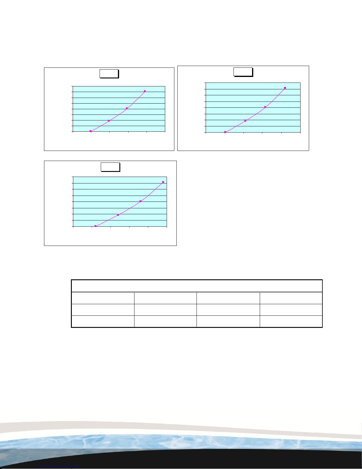
HCF30
0.0
2.0
4.0
6.0
8.0
10.0
12.0
14.0
16.0
0 25 50 75 100 125
Flow (GPM)
Total Head (Ft. of Water)
HCF34
0.0
2.0
4.0
6.0
8.0
10.0
12.0
14.0
16.0
0 30 60 90 120 150
Flow (GPM)
Total Head (Ft. of Water)
HCF36
0.0
2.0
4.0
6.0
8.0
10.0
12.0
14.0
16.0
0 30 60 90 120 150
Flow (GPM)
Total Head (Ft. of Water)
Acceptable Pipe Size For Maximum Recommended System Flow Rate
Pipe Size
Flow Rate GPM
Pipe Size
Flow Rate GPM
2” (63mm)
90 (340 lpm)
4” (100mm)
350 (1325 lpm)
3” (90mm)
200 (757 lpm)
6” (150mm)
800 (3028 lpm)
8. Graph of Filter Pressure Loss
Figure 8-1
Page 16
16
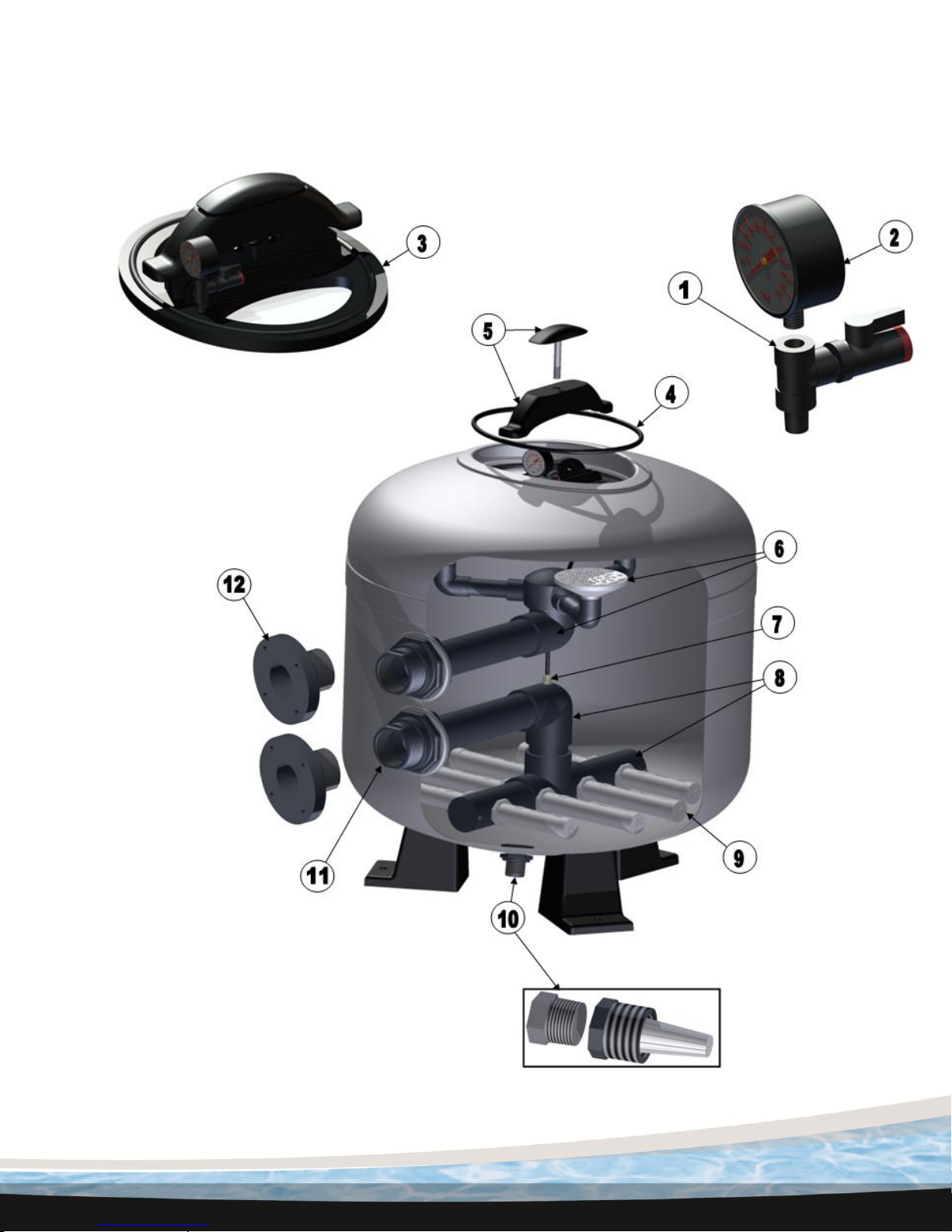
9. Replacement Part Drawing and Numbers
Figure 9-1
Page 17
17
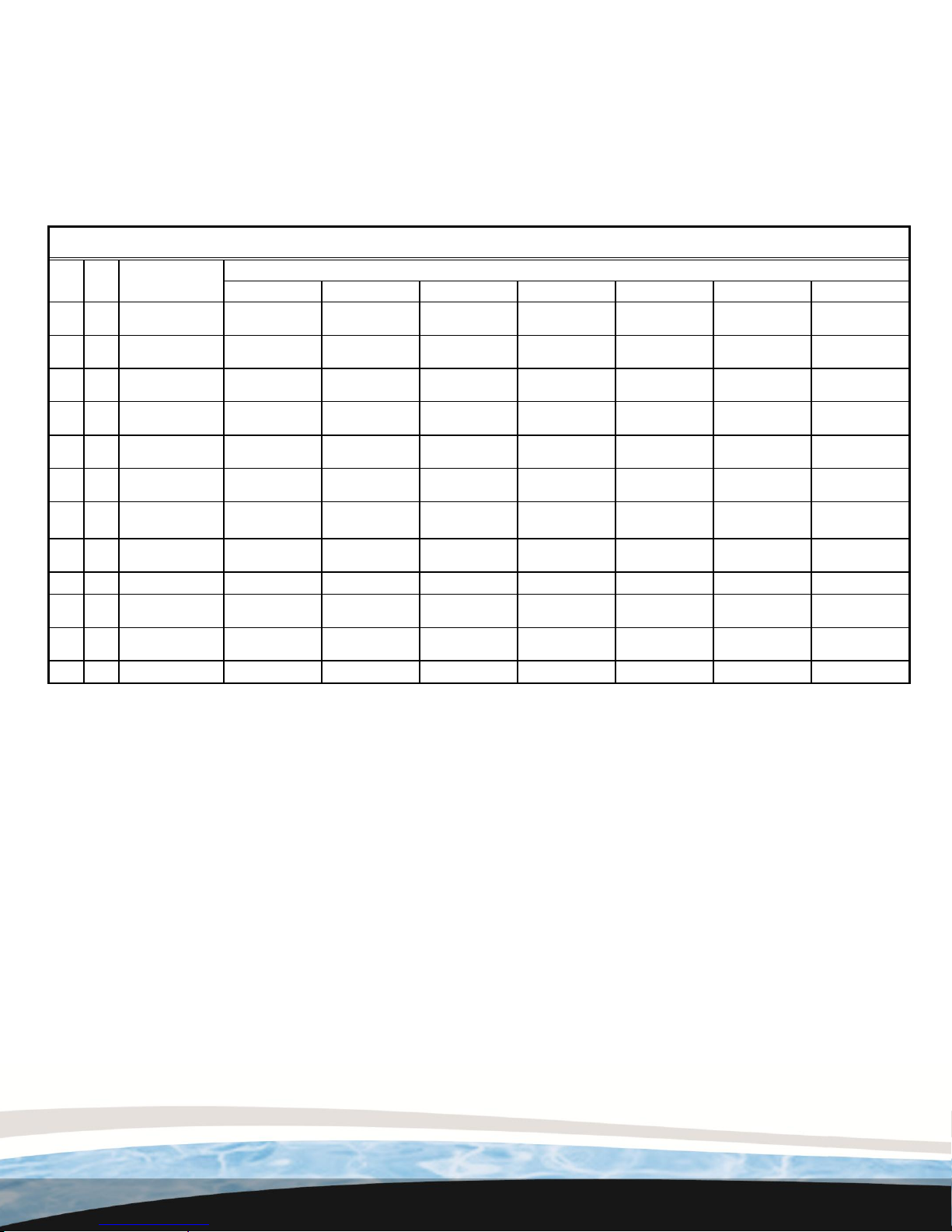
Filter Service Parts List
Item
No.
Qty.
Description
Filter Model Numbers
HCF302T
HCF342T
HCF343T
HCF343F
HCF362T
HCF363T
HCF363F
1
1
External Air Relief
Valve Assembly
HCXFARV1000
HCXFARV1000
HCXFARV1000
HCXFARV1000
HCXFARV1000
HCXFARV1000
HCXFARV1000
2
1
Pressure Gauge -
1/4" Btm Mt
HCXFPGB1000
HCXFPGB1000
HCXFPGB1000
HCXFPGB1000
HCXFPGB1000
HCXFPGB1000
HCXFPGB1000
3
1
Manway Cover
Assembly
HCXFMWC1000
HCXFMWC1000
HCXFMWC1000
HCXFMWC1000
HCXFMWC1000
HCXFMWC1000
HCXFMWC1000
4
1
Manway Cover
Gasket
HCXFMCG1000
HCXFMCG1000
HCXFMCG1000
HCXFMCG1000
HCXFMCG1000
HCXFMCG1000
HCXFMCG1000
5
1
Manway Cover
Yoke & Knob Assy
HCXFMWY1000
HCXFMWY1000
HCXFMWY1000
HCXFMWY1000
HCXFMWY1000
HCXFMWY1000
HCXFMWY1000
6
1
Distribution
Manifold Assembly
HCXFDHA1000
HCXFMWK1001
HCXFMWK1002
HCXFMWK1002
HCXFMWK1003
HCXFMWK1004
HCXFMWK1004
7
1
Internal Air Relief
Assembly
HCXFARA1000
HCXFARA1001
HCXFARA1001
HCXFARA1001
HCXFARA1002
HCXFARA1002
HCXFARA1002
8
1
Collector Manifold
Assembly
HCXFCMA1000
HCXFCMA1001
HCXFCMA1002
HCXFCMA1002
HCXFCMA1003
HCXFCMA1004
HCXFCMA1004
9 1 Lateral Kit
HCXFCLK1000
HCXFCLK1001
HCXFCLK1001
HCXFCLK1001
HCXFCLK1001
HCXFCLK1001
HCXFCLK1001
10
1
Drain Fitting
Assembly
HCXFDFA1000
HCXFDFA1000
HCXFDFA1000
HCXFDFA1000
HCXFDFA1000
HCXFDFA1000
HCXFDFA1000
11
2
Bulkhead Fitting
Assembly
HCXFBFA1000
HCXFBFA1000
HCXFBFA1001
HCXFBFA1001
HCXFBFA1000
HCXFBFA1001
HCXFBFA1001
12 2 Filter Flange Kit 3”
NA
NA
NA
HCXFFFK1000
NA
NA
HCXFFFK1000
Page 18

18
10. Warranty
Hayward® Limited Warranty
To buyer, as original purchaser of this equipment, Hayward Pool Products, 620 Division
Street, Elizabeth, New Jersey, warrants its products free from defects in materials and
workmanship for a period of FIVE (5) years from the date of purchase.
Parts which fail or become defective during the warranty period, except as a result of
freezing, negligence, improper installation, use, or care, shall be repaired or replaced, at our
option, without charge, within 90 days of the receipt of defective product, barring unforeseen
delays.
To obtain warranty replacements or repair, defective components or parts should be returned,
transportation paid, to the place of purchase, or to the nearest authorized Hayward service
center. For further Hayward dealer or service center information, contact Hayward customer
service department, or visit our website at www.Hayward-CommercialPool.com for an
authorized service center near you. No returns may be made directly to the factory without
the express written authorization of Hayward Pool Products.
To original purchasers of this equipment, Hayward Pool Products warrants its products to be
free from defects in materials and workmanship for a period of FIVE (5) years from the date
of purchase.
All other conditions and terms of the standard warranty apply.
Hayward shall not be responsible for cartage, removal and/ or reinstallation labor or any other
such costs incurred in obtaining warranty replacements.
The Hayward Pool Products warranty does not apply to components manufactured by others.
For such products, the warranty established by the respective manufacturer will apply.
Some states do not allow a limitation on how long an implied warranty lasts, or the exclusion
or limitation of incidental or consequential damages, so the above limitation or exclusion may
not apply to you.
This warranty gives you specific legal rights, and you may also have other rights, which vary
from state to state.
Hayward Pool Products, 620 Division Street, Elizabeth, NJ 07207
*Supersedes all previous publications
Page 19

19
Mail to: Hayward Pool Products, 620 Division Street, Elizabeth, NJ 07207; : Attention Warranty Dept
Or, register your warranty online at http://www.haywardnet.com
Please Print Clearly:
COMMERCIAL SAND FILTER
First Name_________________________ Last Name___________________________________
Street Address_________________________________________________________________
City_________________________________________ State___________ Zip______________
Phone Number___________________________________ Purchase Date___________________
E-Mail Address_________________________________________________________________
Serial Number (10-17 digit number)__________________________________________________
Model Number_________________________________________________________________
Pool Capacity_______________(U.S. Gallons)
___ Please include me on all e-mail communications regarding Hayward
®
equipment or promotions.
WARRANTY CARD REGISTRATION
Years Pool has been in service: <1 year ___ 1-3 ___ 4-5 ___ 6-10 ___ 11-15 ___ >15 ___
Purchased from________________________________________________________________
Builder ___ Retailer ___ Pool Service ___ Internet/Catalog ___
Company Name________________________________________________________________
Address______________________________________________________________________
City_____________________________________ State___________ Zip__________________
Phone_______________________________________________________________________
Type of Pool: Concrete/Gunite ___ Vinyl ___ Fiberglass ___ Other_____________________
New Installation ___ Replacement ___
Installation for: In-Ground ___ Above-Ground ___ Spa ___
DETACH HERE: Fill out bottom portion completely and mail within 10 days of purchase/installation or register online.
12. Warranty Card Registration
DATE OF INSTALLATION ____________________________________________________ _
INITIAL PRESSURE GAUGE READING (CLEAN FILTER) _______________________________
PUMP MODEL ________________________ HORSEPOWER ______________________ _
* Retain this Warranty Certifi cate in a safe and convenient location for your records.
11. Product Registration
 Loading...