

Page 1
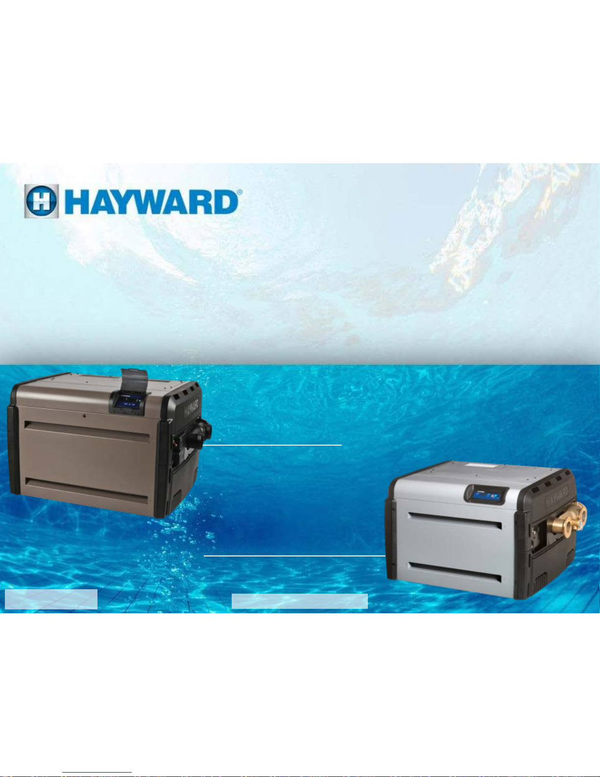
HxxxFD(N/P)ASME
Universal H S eries Heaters
T roubles hooting Guide
HxxxFD(N/P)
TSG-UHS16b
Copyright 2017 Hayward Industries Inc.
Page 2
High Voltage Electrocution Hazard
Hazardous voltage can shock, burn, cause serious injury
and or death. To reduce the risk of electrocution and or
electric shock hazards:
• Only qualified technicians should remove the panel
• Replace damaged wiring immediately
• Insure panel is properly grounded and bonded
2
!
Warning
Safety Precautions
Page 3

3
Table of Contents
ICB and Fuse Board Layout 4-6
UHS Sequence of Operation:
Normal/Failure to Light
7-8
UHS Gas and Electrical Connections
9-11
How To:
Pg.
12-17
Program Heater Bypass &
Temperature Lockout
13-15
Test/Adjust Gas Pressure 16-17
Troubleshooting:
Pg.
18-64
Diagnostic Codes and Part Numbers
19-20
1. Heater not powering up
21-26
2. Open FC1&/FC2 Fuse
27-28
3. Open FC3&/F1 Fuse
29-31
4. Open FC4 Fuse
32-33
5. “BD” Code
34-35
6. “EE” or “CE” Code
36-37
Troubleshooting (cont.):
Pg. 18
-64
7. “IO” or “SB” Code
38
-39
8. “SF” or “HS” Code
40
-41
9. “PF” Code
42
-43
10. “HF” Code
44
-45
11. “LO” Code
46
-51
12. “IF” Code
52
-55
13. “AC” Code
56
-57
14. “AO” Code
58
-60
Heat Exchanger:
Flow requirements
61
Heat Exchanger: Inspection
62
Heat Exchanger: Potential Failure Causes
63
UHS Wiring Schematic
64
UHS
Wiring Diagram
65
Page 4
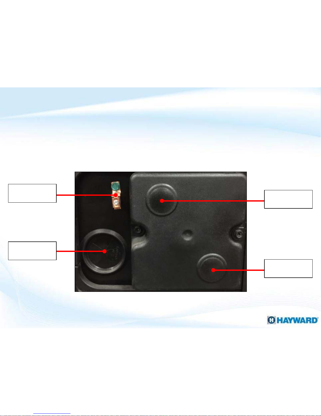
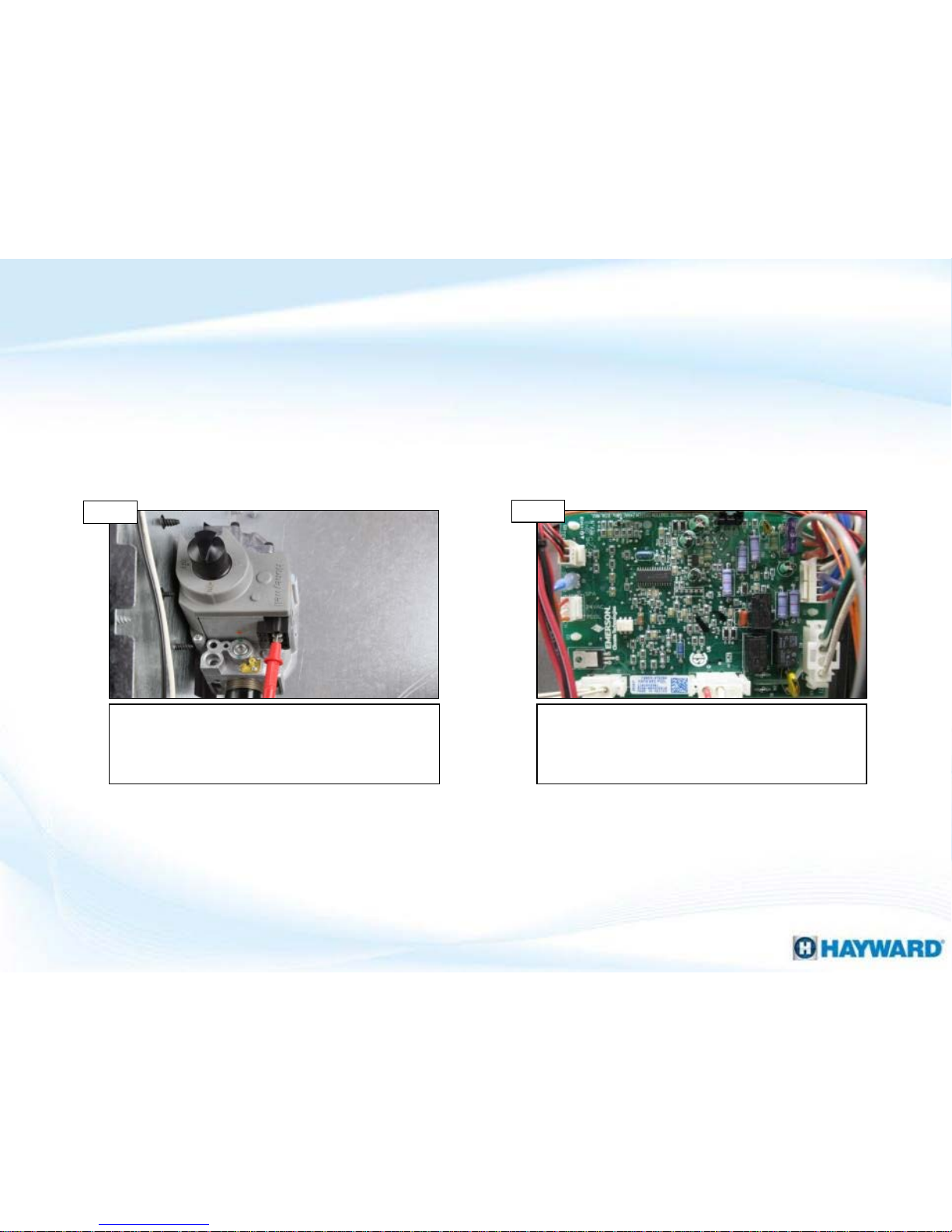
4
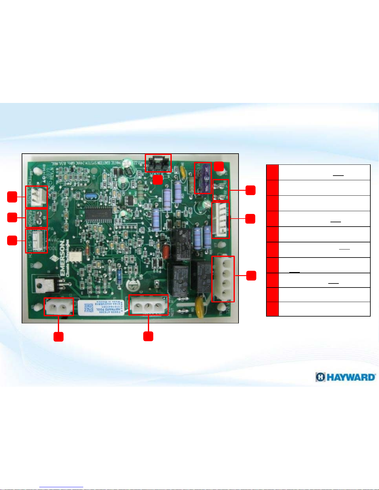
A
Remote Control: 24VAC (E1)
B
Flame Sensor (E4)
C
Temperature Sensor (E2)
D
Display Output: 24VAC (E7)
E
3A Fuse (F1)
F
Low Voltage R & C: 24VAC (E12,
E13)
G
Gas Valve & Safety Switches:
24VAC (E11)
H
High Voltage: 120VAC (E10)
I
Blower/Inducer (E6)
J
Ignitor (E3)
C
H
G
F
D
E
J
I
B
A
Integrated Control Board Layout (ICB)
Page 5
5
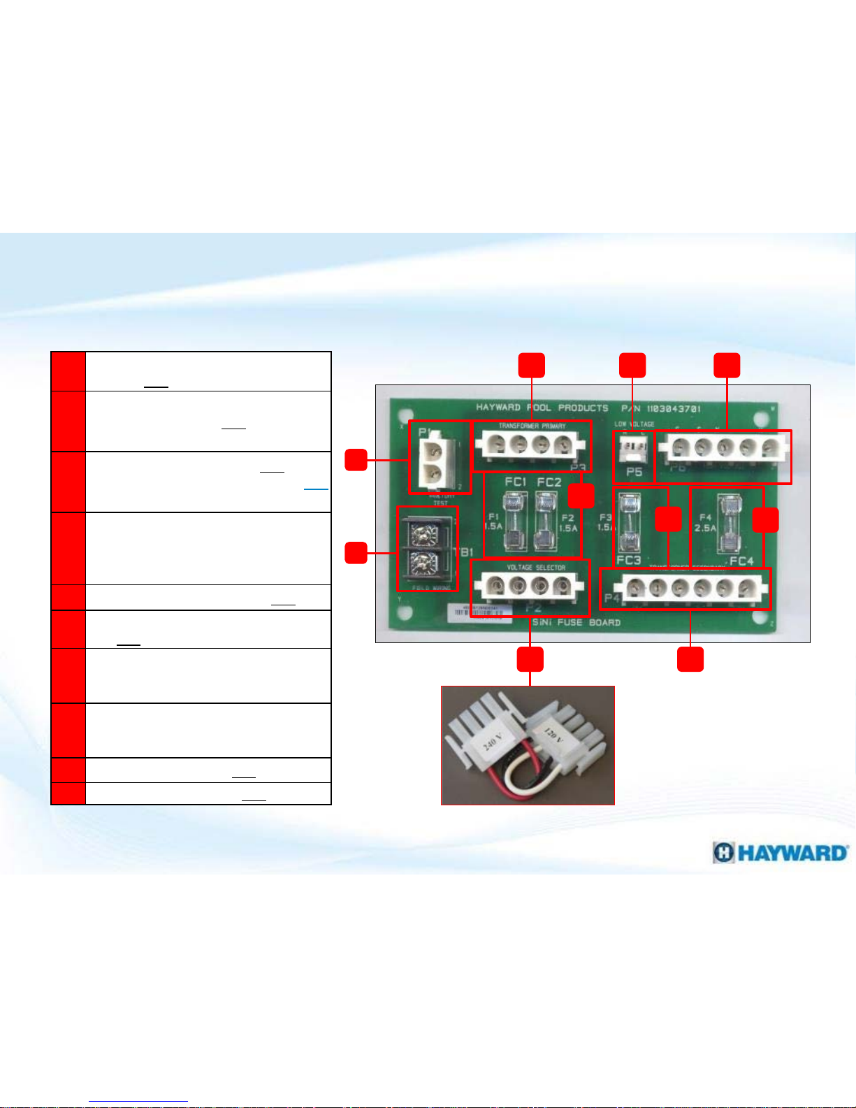
A
Power connection for junction boxes:
120/240VAC (P1) After Aug 08
B
Terminal block for field wiring
connections: 120/240VAC (TB1) Before
Aug 08 Input
C
Voltage Selector 240 OR 120VAC
determined by plug (P2): NOTE: 240VAC
plug factory installed
D
Fuse: 3A protect primary input voltage,
will fail with excessive voltage, improper
wiring, shorted transformer or fuse
board (FC1 & FC2)
E
Transformer Primary: 120/240VAC (P3)
F
Transformer Secondary: 24 (left) &
120VAC (right) (P4)
G
Fuse: 1.5A protects transformer
secondary, will fail if short occurs
between fuse & ICB (FC3)
H
Fuse: 2.5A protects transformer high
voltage secondary, will fail with blower,
ignitor or ICB failure (FC4)
I
Low Voltage Output: 24VAC (P5)
J
High Voltage Output: 120VAC (P6)
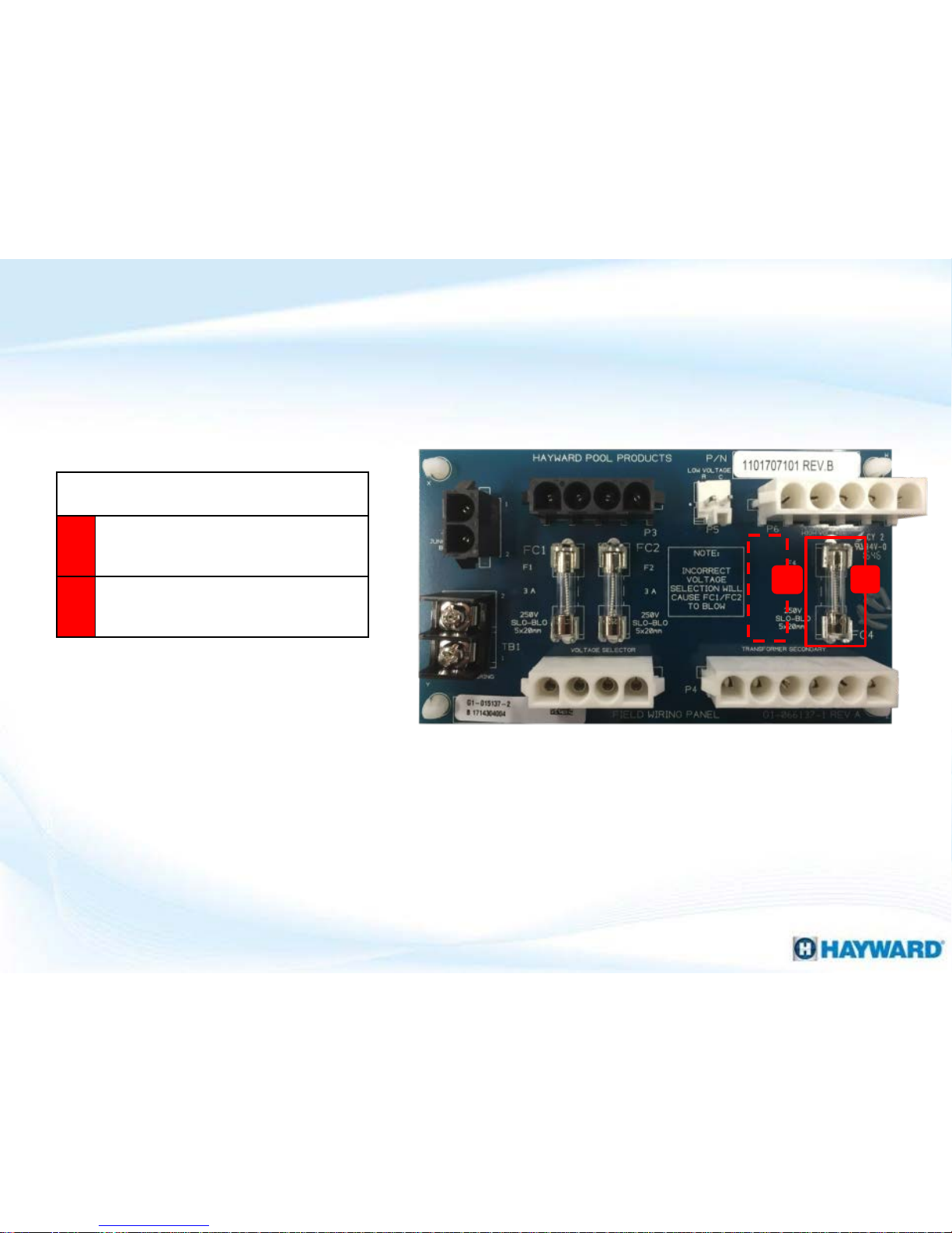
Fuse Circuit Board Layout
A
B
C
E
F
G
H
J
I
Fuse board configuration Prior to November 2010 (Older Style)
D
Page 6
6
Fuse Circuit Board Layout
H
Fuse board configuration as of November 2010 (Newer Style)
Changes compared to older style fuse board:
G
Fuse: (FC3) has been removed, since the
F1 fuse was added to the ICB
H
Fuse: (FC4) is now a 3A fuse, matching
the FC1 & FC2
NOTE: Fuses located on THIS board are all 250v SLO-BLO 5 x 20 mm.
Hayward Part # FDXLFSK19F30 (Qty. 10)
G
Page 7

The control continually compares the set temp to the actual water temp. When
the water temp is 1º below the set point the following sequence starts:
1. The control checks for open blower vacuum switch
2. Blower starts pre-purge cycle as the ignitor heats up (20 Sec).
3. The control checks for a closed blower vacuum switch.
4. At proper ignitor temp, a 4 second trial begins. Gas valve opens and
monitors flame sense. The blower will turn off for one second. The ignitor
is de-energized at flame sense or at completion of 4 sec trial. If the flame is
sensed, The blower vacuum switch, control loop, temp sensor & flame
sensor are constantly monitored during call for heat.
5. When set temp is reached, the control ends the call for heat. The gas valve
is de-energized, and the flame is extinguished.
6. The blower will operate for a 30 second post purge.
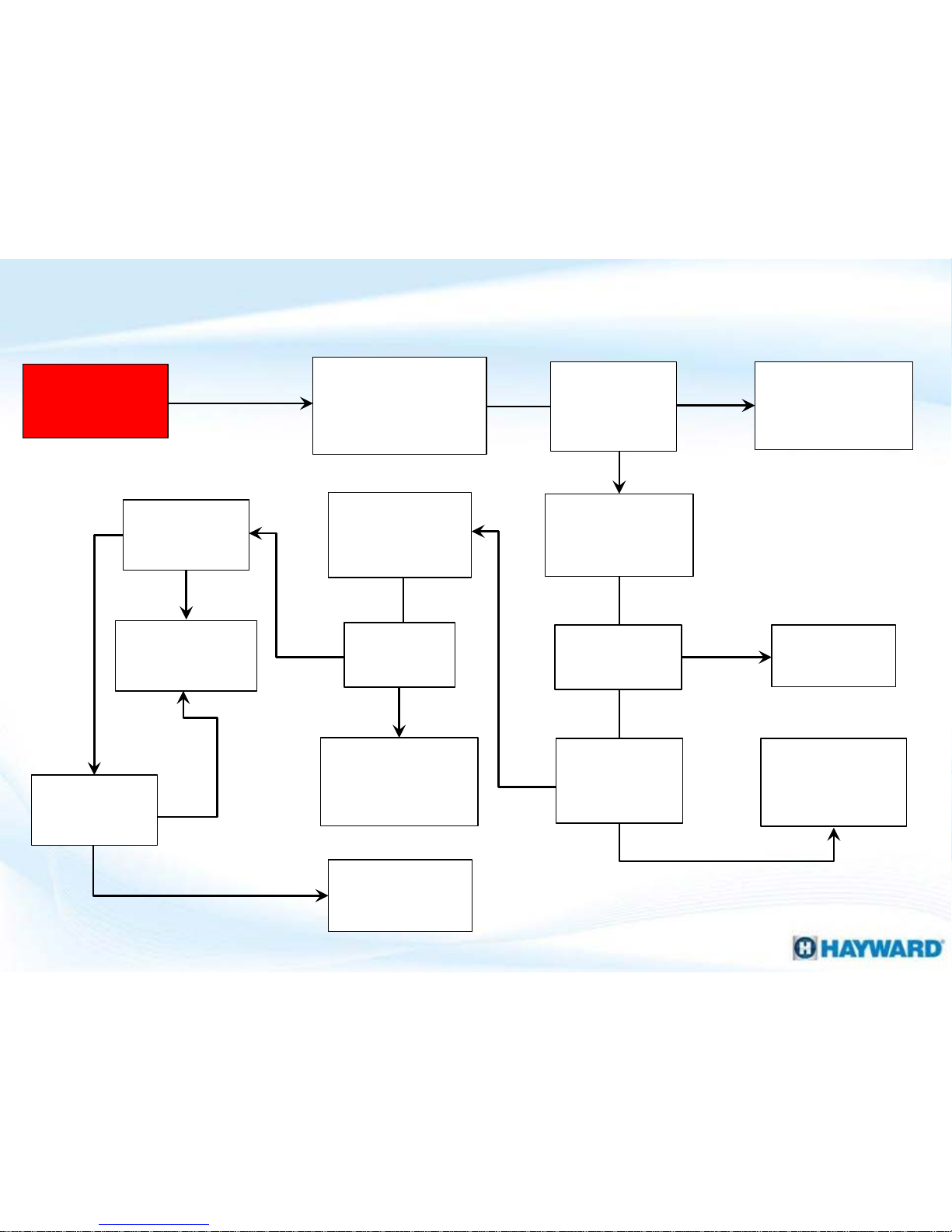
7
UHS Sequence of Operation: Normal
NOTE: If during step four, the heater fails to fire, please procced to the next page for
more details outlining failure to light operations.
Page 8

If trial fails:
1. Gas valve de-energizes (for 30 second, blower post purge).
2. Starts over at #2 of heating mode sequence.
3. Retries 3 times until lockout (IF code).
4. Waits 60 minutes then retries 3 more times.
5. Will continue to retry every 60 minutes, until demand for heat is
stopped.
NOTE: When making keypad entries of any type there may be a 5-10 sec delay for
certain situations.
8
UHS Sequence of Operation: Failure to Light
Page 9
9
UHS Electrical & Gas Connection
Connections located on both the left & right side of heater cabinet
Low Voltage
High Voltage
Gas Supply
Bonding Lug
Electrical & Gas connections as of September of 2008 (Newer Style)
Page 10
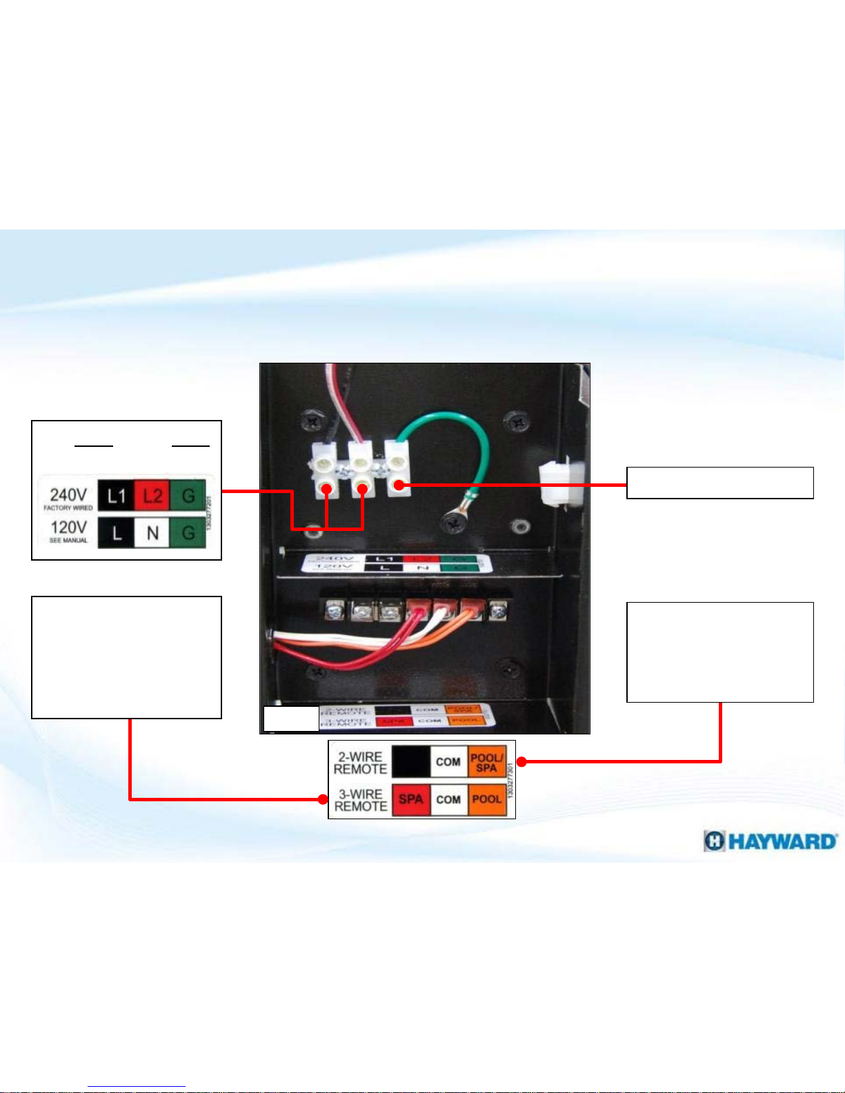
10
Electrical & Control Connections (cont.)
Fig. 1
Ground connection
Two Wire Remote
Connection:
Orange (Pool) and
White (Common)
Three Wire Remote
Connection:
Orange (Pool),
White (24V), & Red
(Spa).
120VAC or 240VAC
Connection
Electrical connections as of September of 2008 (Newer Style)
Page 11
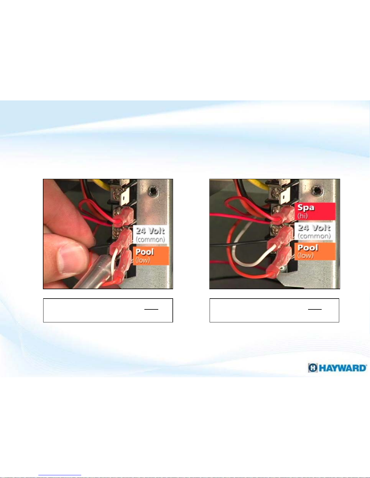
NOTE: Control hookup located outside control box.
11
Orange (Pool) & White (24VAC,
Common)
Orange (Pool), White (24VAC,
Common), & Red (Spa)
Three wire hook-up
Two wire hook-up
Electrical & Control Connections (cont.)
Electrical connections prior to September of 2008 (Older Style)
Page 12

Universal H Series Heaters®
How To:
Page 13

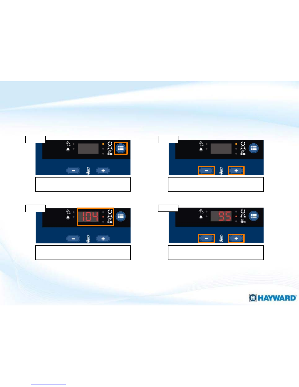
13
How To: Program Heater Bypass Operation
Follow the included steps to place the heater in bypass mode for external control.
NOTE: the maximum temperature set point is 104° F.
Press the ‘MENU ICON’ button to place the
heater in ‘STANDBY’.
Press and hold the minus button and ‘MENU
ICON’ button for 3 seconds.
‘bo’ should appear on the display when the
heater has successfully entered bypass mode.
Once in bypass, press the ‘MENU ICON ’
button until ‘POOL’ or ‘SPA’ is illuminated.
Step 2
Step 3
Step 4
Step 1
Page 14
14
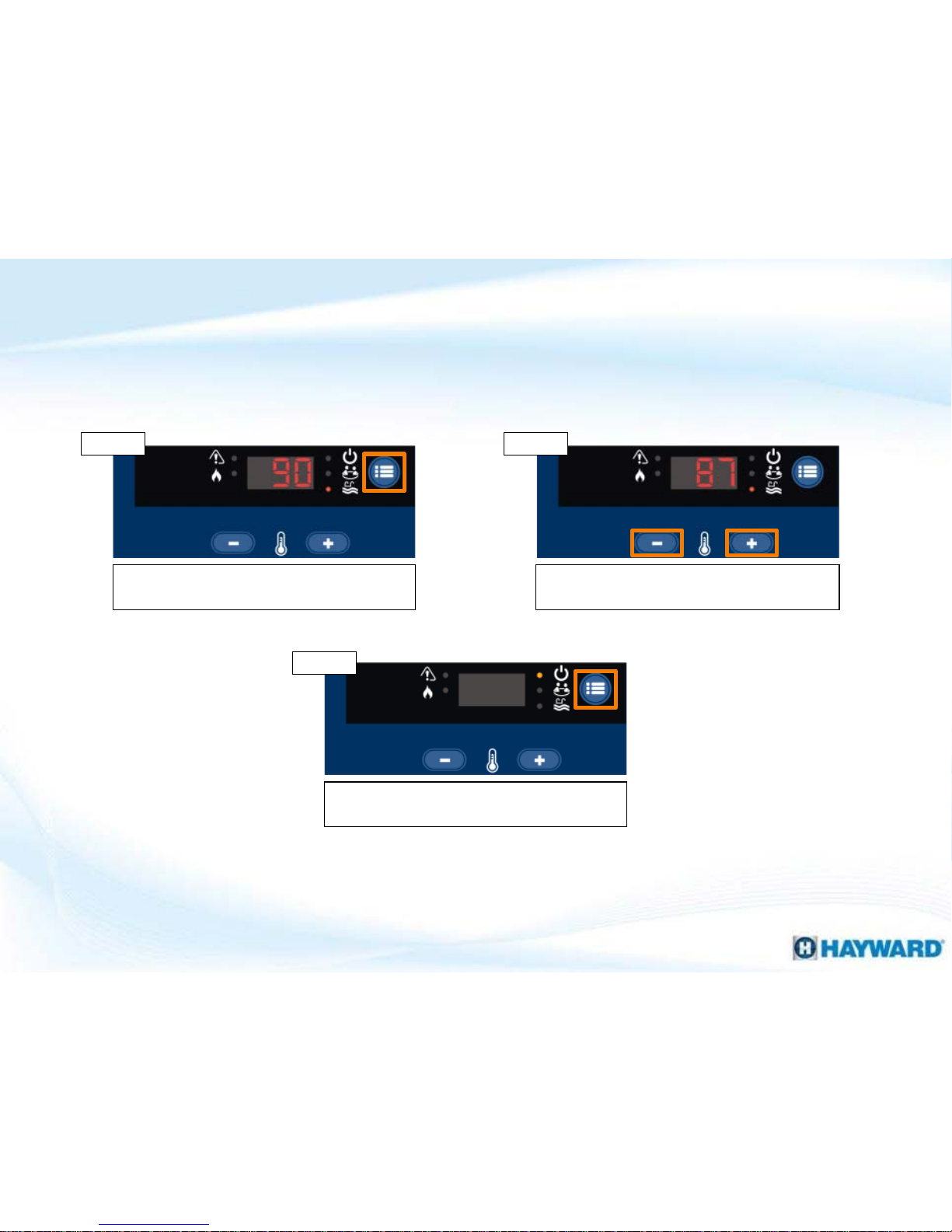
How To: Program Temperature Lock-Out
NOTE: The default Max temp lock-out set points are 90ºF (Pool) 104ºF (Spa).
Press the ‘MENU ICON’ button to place the
heater in ‘STANDBY’ mode.
Press and hold the minus & plus buttons for 3
seconds.
The ‘SPA’ indicator should illuminate & the
display should show the Max Temp set point.
Raise or lower the temperature displayed
using the minus or plus button.
Step 2 Step 1
Step 3
Step 4
Follow the included steps to place the heater in bypass mode for external control.
Page 15
15
How To: Program Temperature Lock-Out (cont.)
NOTE: When setting the max temp lock-out set point, the LEDs & display
should flash rapidly.
Press the ‘MENU ICON’ button to toggle to the
‘POOL’ now that the ‘SPA’ is set.
Raise or lower the temperature displayed
using the minus or plus button.
To finalize, press the ‘MENU ICON’ button
until the heater goes back into ‘STANDBY’.
Step 6 Step 5
Step 7
This feature is available on heaters manufactured after February 25th 2011.
Page 16
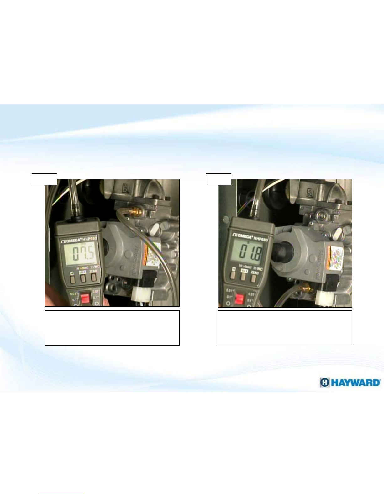
16
Measure the inlet static pressure
(valve off) & load pressure (valve
on / energized).
Measure the outlet manifold
pressure (valve on / energized), as
shown below.
The static & load values should be
within the levels listed on the data
plate, example on Page 17.
Manifold reading should be
between 1.8”- 2.0” w.c for natural
Gas or 6.8”- 7.0” w.c for propane.
NOTE: Please refer to Installation Manual for proper gas line sizing.
Step 1
Step 2
How To: Test/Adjust Gas Pressure
Page 17
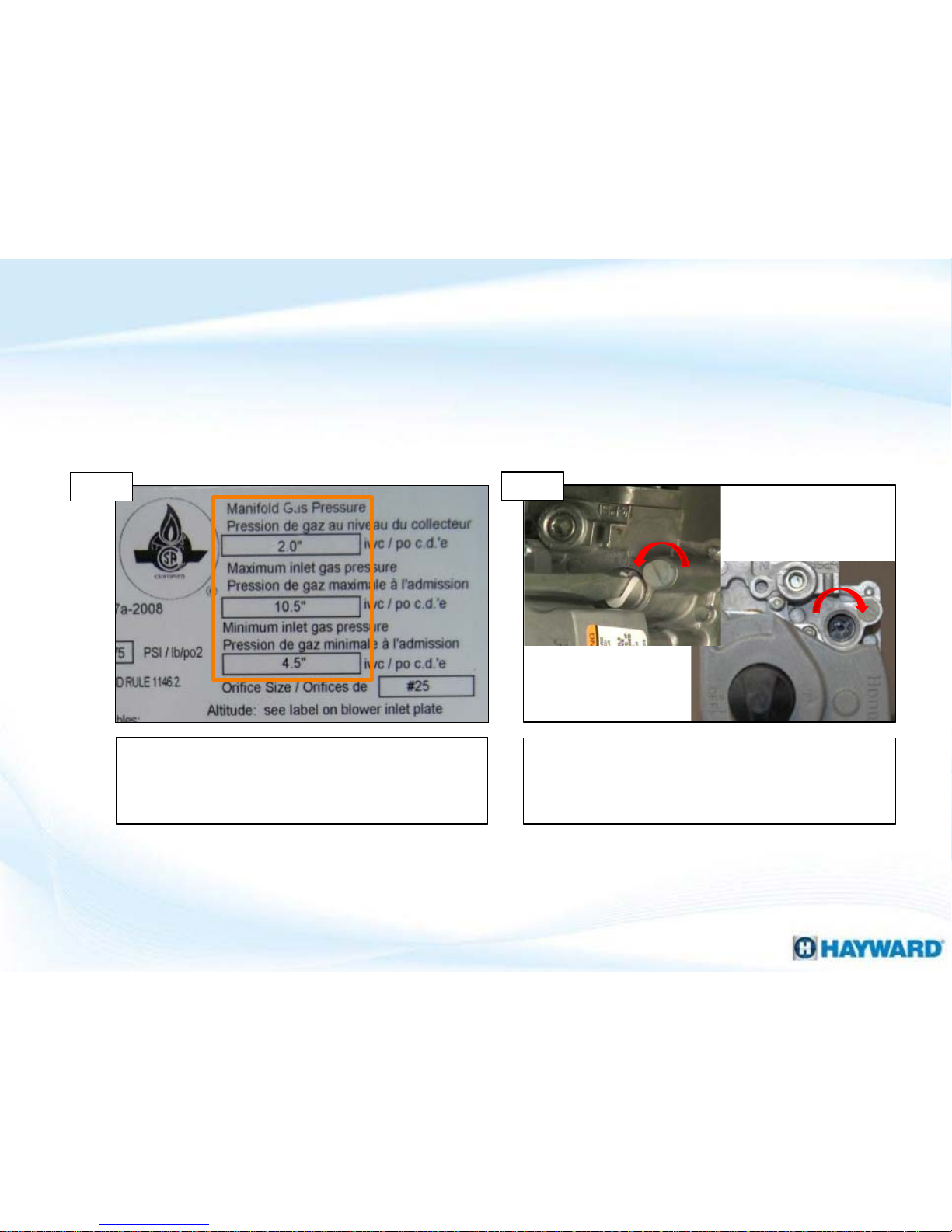
IF inlet pressures are correct AND the
manifold pressure is high or low, go to
step 4.
*NOTE: Before any adjustment occurs, verify inlet gas pressure meets the requirement
set forth by the data plate on the heater. IF it does, continue to step 4. IF NOT, refer to
installation manual and/or contact installer.
Verify heater specifications off the heater
plate (bottom front inside heater)
17
How To: Test/Adjust Gas Pressure (cont.)
Step 3
*Adjust the manifold pressure
(at the gas valve)
Remove plug. Once removed, increase
pressure by rotating valve clockwise,
(counter clockwise to reduce pressure).
Step 4
NOTE: IF incoming gas pressure is within range, then your manifold pressure
should be correct per factory settings.
Page 18
Universal H Series Heaters®
Troubleshooting:
Page 19
Below is a list of all Diagnostic Codes for the UHS Heater. Troubleshooting Steps for
each Code are covered on the following pages.
Diagnostic
Code
Description
AC Blower Vacuum Switch closed
AO Blower Vacuum Switch open
BD Bad board or secondary high voltage fault
CE Communication Error Between Control Module and Display Interface Assembly
EE Bad board
HF Flame present with Gas Valve not energized.
HS
Maximum return water temperature exceeded and / or rapid water temperature rise.
IF Ignition Failure
IO Ignitor Circuit Open
LO Water Pressure Switch, Vent Pressure Switch, or Temperature Limit Switch Fault
PF Voltage polarity reversed, low voltage detected
SB Keypad failure
SF Temperature Sensor (thermistor) input failure
19
Diagnostic Codes
Page 20
The following outlines the various replacement parts required for this
troubleshooting guide.
Part Number:
(H150-H400)
Part Number:
(H500)
Description
IDXL2TRF1930 IDXL2TRF1930 Transformer
FDXLFWP1930 FDXLFWP1930 Fuse Board (field wiring panel)
FDXLWHA1930 FDXLWHA1930 Wiring Harness Kit (complete)
FDXLICB1930 FDXLICB1930 ICB (integrated control board)
IDXL2DB1930 IDXL2DB1930 Prio r 07 /16-Display Board (only)
FDXLBKP1930 FDXLBKP1930 Prior 07/16-Bezel/Keypad Assy.
*FDXLBKP1932 *FDXLBKP1932 Display/Bezel/Keypad Assy.
FDXLBCP1150 Kit-Bezel Control Panel 150
FDXLBCP1200 Kit-Bezel Control Panel 200
FDXLBCP1250 Kit-Bezel Control Panel 250
FDXLBCP1300 Kit-Bezel Control Panel 300
FDXLBCP1350 Kit-Bezel Control Panel 350
FDXLBCP1400 Kit-Bezel Control Panel 400
FDXLBCP1500 Kit-Bezel Control Panel 500
20
Troubleshooting Part Numbers
Part Number:
(H150-H400)
Part Number:
(H500)
Description
FDXLBWR1930 FDXLBWR1500 Blower
FDXLIGN1930 FDXLIGN1930 Ignitor
FDXLTER1930 FDXLTER1930 Thermistor (temperature sensor)
IDXL2SNT1930 IDXL2SNT1930 Combustion Blower Tube Kit
FDXLEGL1931 FDXLEGL1931 Exhaust Gas Limit Switch
FDXLHLI1930 FDXLHLI1930 High Limit Kit (temperature limits)
IDXLFLS1930 IDXLFLS1930 Flame Sensor (3” & 5”)
FDXLFSK1930 FDXLFSK1930 Fuse Kit
FDXLWPS1930 FDXLWPS1930 Water Pressure Switch
FDXLBVS1930 FDXLBVS1930 Blower Vacuum Switch
FDXLBRN1930 FDXLBRN1930 Burner Kit
*FDXLGSV0001 FDXLGSV1500N Gas Valve (Natural Gas)
FDXLGSV002
FDXLGSV1500P Gas Valve (Propane)
FDXLVPS1930 FDXLVPS1930 Vent Pressure Switch
* Heaters made prior to 07/16 that want the new display/bezel/keypad, will need to replace
the old display with the Kit-Bezel Control Panel specific to their model heater.
Page 21

1. Heater Not Powering Up
Heater not
powering up
Correct source
power issue
YES
NO
Correct voltage
selector plug?
NO
Inspect wires &
connections,
are they OK?
YES
Test FC1 &
FC2 fuses
Is incoming
power correct?
Is either
fuse blown?
Go to:
Section 2
Test 22-28VAC
between R & C on
P5 (fuse board)
Test
transformer
output for 22-
28VAC
Is voltage
correct?
NO
Replace fuse
board:
FDXLFWP1930
NO
Install correct
plug and
retest
Replace harness
and/or reseat
connection:
FDXLWHA1930
YES
YES
NO
Test transformer input
for 110-125VAC
YES
Is voltage
correct?
Replace
transformer:
IDXL2TRF1930
YES
NO
Is voltage
correct?
YES
Go to section B
(next page)
NO
Replace fuse
board:
FDXLFWP1930
21
Page 22

1. Heater Not Powering Up (cont.)
YES
NO
Inspect wires &
connections,
are they OK?
Disconnect and
test the red &
grey wires on ICB
for 22-28VAC.
YES
Replace wire
harness:
FDXLWHA1930
Section B
(continued from
previous page)
Secure
wiring/plugs
and retest
Is voltage
correct?
NO
On ICB, test 3A
fuse for
continuity
Is fuse
blown?
NO
YES
On the ICB, verify
22-28VAC
between AC &
COM (pins 1&4)
Replace fuse:
FDXLFSK1930
then go to
section 3.
Is voltage
correct?
Replace the ICB:
FDXLICB1930
Replace display/
bezel/keypad:
(See Pg. 20)
NO
YES
Page 23

For models manufactured prior to August of 2008,
proceed to step 1B. IF model is later, go to 1C.
Verify input power
Verify 110-125 or 220-245VAC off fuse board (TB1).
IF correct, go to 1D. IF NOT, correct source power.
Verify heater manufacture date
Step 1A Step 1B
IF voltage is present, go to step 1D. IF voltage is
incorrect, correct source power.
Models after August 2008
Step 1C
23
Verify selector plug matches incoming line power.
IF it does not, power OFF & correct. IF OK, go to 1E.
Voltage selector plug
Step 1D
1. Heater Not Powering Up
Page 24

Inspect Fuse Board wiring, ensuring all plugs are
securely fastened. IF correct, proceed to step 1F.
Test Fuses
Verify that FC1 & FC2 fuses aren’t open. Replace all
open fuses & go to section 2. IF correct, go to 1G.
Inspect connections
Step 1E
Step 1F
Disconnect the P3 plug from the fuse board. Test
110-125VAC between pins 1&2 and 3&4 on the
board. IF good, go to 1H. IF NOT, replace the Fuse
board (pg. 20).
Test transformer input
Step 1G
24
Disconnect P4 plug from fuse board. Verify 22-
28VAC between pins 1 & 2 (red wires), then 110-
125VAC between pins 4-6 (grey wires). IF correct,
go to 1I. IF incorrect replace transformer (pg.20).
Test transformer output
Step 1H
1. Heater Not Powering Up (cont.)
Page 25

NOTE: Step 1I – Heaters older
than 11/2010 – If no voltage
across R & C, remove
FC3 fuse and test for
continuity. IF open go to page
24. IF OK go to Step 1J
Disconnect the plug from P5 (on fuse board). Test
22-28VAC between R & C. IF no voltage, replace
Fuse Board (pg. 20). If correct, go to step 1J.
Inspect wiring
Inspect ICB wiring, ensuring all plugs are securely
fastened. IF wiring is OK go to Step 1K. IF NOT,
secure wiring/plugs then retest.
Test P5 (low voltage)
Step 1I
25
Step 1J
1. Heater Not Powering Up (cont.)
Disconnect and test the red and grey wires from
the ICB. IF 22-28VAC is present go to step 1L. IF
NOT, replace wire harness (pg. 20).
Test ICB input (low voltage)
Step 1K
Page 26

Test F1 (3AMP) fuse
On the ICB, locate and test the 3A fuse for
continuity. IF fuse is blown, replace it and go to
section 3. IF Ok, go to step 1M.
On the ICB, verify 22–28VAC between AC & COM
terminals (pins 1 & 4). IF voltage is present, replace
display/bezel/keypad. IF no voltage, replace ICB
(pg. 20).
Test ICB’s display output
26
1. Heater Not Powering Up (cont.)
Step 1L
Step 1M
Page 27

27
2. Open FC1 &/or F2 Fuse
Open FC1
&/or F2 Fuse
YES
Correct voltage
selector plug?
NO
Install correct
plug and
replace fuse
Did this
correct the
problem?
YES
NO
Is transformer
wiring damaged,
pinched, or worn?
Problem
solved
Test
transformer
resistance
Correct/repair
transformer
wiring
YES
NO
Is resistance
correct?
NO
YES
Replace
transformer:
IDXL2TRF1930
Contact
Support
(908) 355-7995
Page 28

IF voltage selector plug matches voltage, go to step
2B. IF not, power down, replace FC1 & FC2 fuses, &
switch plug to proper voltage.
Inspect transformer wiring
Inspect transformer wiring, ensuring the insulation
on the wiring is not damaged. IF damaged replace
transformer (pg. 20). IF OK go to 2C.
Verify voltage selector plug
Step 2A
With power off, remove the P3 & P4 plugs. On the P3 plug measure resistance between the
orange & yellow wires for 1.9 – 2.9 Ohms, then do the same between the black and brown
wires. IF resistance is out-of-range, replace transformer (pg. 20). IF OK and problem still
persists, contact technical support: (908) 355.7995.
Test transformer resistance
28
Step 2B
2. Open FC1 &/or F2 Fuse
Step 2C
Page 29

29
3. Open FC3 &/or F1 Fuse
Open FC3
&/or F1 Fuse
Check the remote
connection/high
limits
Is low voltage
wiring damaged,
pinched, or worn?
Is water pressure
switch wiring
damaged, pinched,
or worn?
Replace wire harness:
FDXLWHA1930
OR high limit if damaged:
FDXLHLI1930
YES
NO
YES
Are any wires
showing
continuity?
NO
Is blower vacuum
switch wiring
damaged, pinched,
or worn?
YES
Is gas valve wiring
damaged, pinched,
or worn?
NO
NO
YES
Test gas valve
wires for
continuity against
ground
Replace gas
valve:
(pg. 20)
YES
Inspect ICB
wiring, any wires
compromised?
YES
Replace wiring
harness:
FDXLWHA1930
Replace ICB:
FDXLICB1930
NO
Replace wire harness:
FDXLWHA1930
OR pressure switch if
damaged:
FDXLWPS1930
Replace wire harness:
FDXLWHA1930
OR vacuum switch if
damaged:
FDXLBVS1930
Replace wire harness:
FDXLWHA1930
OR Replace gas valve:
Please refer to (pg. 20)
NO
Page 30

Power down and inspect all remote connections
and high limit wiring for damage. IF damaged,
repair/replace (pg. 20). IF OK, go to step 3B.
Inspect water pressure switch
With power off, inspect the water pressure switch
wiring for damage. IF damaged, replace the wire
harness (pg. 20). IF OK, go to step 3C.
Inspect connections/high limits
Step 3A
With power off, inspect the blower vacuum switch
wiring for damage. IF damaged, replace the wire
harness (pg. 20). IF OK, go to step 3D.
Inspect blower vacuum switch
Step 3C
30
With power off, inspect the gas valve wiring for
damage. IF damaged, replace the wire harness (pg.
20). IF OK, go to step 3E.
Inspect gas valve wiring
Step 3D
Step 3B
3. Open FC3 &/or F1 Fuse
Page 31
With power off, measure resistance, comparing
each terminal to ground. IF any terminal shows
continuity, replace the gas valve (pg. 20). IF OK, go
to step 3F.
ICB wiring
Inspect ICB wiring. IF wiring is damaged, replace
the wire harness with a new wire harness kit (pg.
20). IF OK and the problem still exists, replace the
ICB (pg. 20)
Verify gas valve is not shorted
Step 3E
31
Step 3F
3. Open FC3 &/or F1 Fuse (cont.)
When testing the gas valve, if continuity appears between any wires and ground, then
this implies a short has occurred and the gas valve will need to be replaced (refer to
pg. 20 for part number).
Page 32

32
4. Open FC4 Fuse
Open FC4
Fuse
Inspect ignitor
wiring for
damage
Is ignitor wiring
damaged, pinched,
or worn?
Is blower wiring
damaged, pinched,
or worn?
Replace ignitor:
FDXLIGN1930
YES
NO
YES
NO
Is the resistance
incorrect?
NO
YES
Ohm out blower for 8-
9ohms (before Sept.
2010) OR for 4-5ohms
(after Sept. 2010), is
resistance correct?
YES
NO
Replace blower:
Please refer to (pg. 20)
Replace ignitor:
FDXLIGN1930
Ohm out the
ignitor verifying:
8-25ohms
Contact
Support
(908) 355-7995
Replace blower:
Please refer to (pg. 20)
Page 33

Inspect the Ignitor & Blower wiring. Verify
insulation is not damaged. IF wires are damaged,
replace the damaged part (pg. 20). IF OK, go to 4B.
Verify ignitor resistance
Disconnect ignitor from ICB & measure resistance
of ignitor. Verify 8-25 ohms between 20°-140°F. IF
correct, go to 4C. IF NOT, replace ignitor (pg. 20).
Ignitor and blower wiring
Step 4A
33
Step 4B
4. Open FC4 Fuse
With power off, disconnect blower plug from ICB. Models manufactured before Sept. 2010:
measure across pins 1-2 (black & red), then 3-4 (white & blue) for 8-9 ohms. Models after Sept.
2010: measure for 4-5 ohms across the two terminal with wires. IF out-of-range, replace
blower (pg. 20). IF correct, contact technical support (908)355-7995.
Measure blower resistance
Step 4C
Before Sept. 2010
Page 34

34
5. Service LED ON: ‘BD’ Code
‘BD’ Code
Power down and
check the FC4
fuse
Is fuse blown?
Disconnect P6 and
test for 110 -
125VAC between
pins 3-5.
Proceed to:
Section 4
YES
NO
YES
NO
On P4, verify 110-
125VAC between
4-6 (grey wires)
YES
Is voltage
correct?
Is voltage
correct?
Replace fuse
board:
FDXLFWP1930
NO
Replace
transformer:
IDXL2TRF1930
Verify E10 for 110-
125VAC between
1-3 (white & black)
Is voltage
correct?
YES
NO
Replace
transformer:
IDXL2TRF1930
Replace wire
harness:
FDXLWHA1930
Page 35

With power off, verify the FC4 fuse has continuity.
IF fuse is good, go to 5B. IF fuse is blown, go to
Section 4.
Verify ICB output
Disconnect the P6 connector and test voltage for
110-125VAC between pins 3-5. IF no/low voltage,
go to step 5D. IF correct, go to 5C.
Test the FC4 fuse (continuity)
Step 5A
Disconnect the E10 connector from ICB. Verify 110-
125VAC between 1-3 (white & black). IF present,
replace ICB. IF NOT, replace wire harness (pg. 20).
Verify ICB input
Step 5C
35
Disconnect P4 from fuse board. Verify 110-125VAC
between 4-6 (grey wires). IF OK, replace fuse
board. IF NOT, replace transformer (pg. 20).
Verify transformer output
Step 5D
Step 5B
5. Service LED ON: ‘BD’ Code
Page 36

36
“EE” OR
“CE” Code
Check display for
“EE” code
Is “EE” code
present?
The “CE” code may
clear with a reset of
power, power cycle
the heater
YES
NO
Are
connections
secure?
Check display
ribbon cable
connection
6. Service LED ON: “EE” OR “CE” Code
Replace ICB:
FDXLICB1930
Did the “CE”
code clear?
YES
NO
Secure
connections
& retest
NO
YES
Did “CE” code
clear?
YES
Problem
solved
NO
Replace
display/bezel/
keypad:
(See Pg. 20)
Replace ICB:
FDXLICB1930
Go to
section B
Section B
Did the “CE”
code clear?
Problem
solved
YES
Contact
Support
(908) 355-7995
NO
Page 37

“EE” error indicates the you have a defective ICB
board. IF this error appears, replace ICB (pg. 20). IF
no EE error, go to 6B.
Check display for “CE”
“CE” (communication error) indicates a problem
between the ICB & display board. Cycle power
OFF/ON. IF error persists, go to 6C.
Check display for “EE”
Step 6A
Verify ribbon cable is secure. IF cable is secure,
replace display/bezel/keypad assy. (pg. 20) then go
to 6D. IF NOT secured, reconnect.
Inspect display connections
Step 6C
37
IF after replacing display/bezel/keypad, “CE” error
persists, replace ICB (pg. 20). IF replacing ICB fails
to solve problem, contact support (908) 355-7995.
Verify “CE” has cleared
Step 6D
Step 6B
6. Service LED ON: “EE” OR “CE” Code
Page 38

“IO” OR
“SB” Code
Check display for
“IO” code
Is “IO” code
present?
The “SB” code may
clear with a reset of
power, power cycle
the heater
YES
NO
Verify ignitor wiring is
not damaged and
plugged in securely
7. Service LED ON: “IO” OR “SB” Code
38
Is ignitor wire
damaged?
Replace ignitor:
FDXLIGN1930
YES
NO
Ohm ignitor, verify
8-25 ohms (20°-
140°F), reading out
of range?
YES
NO
Replace ICB:
FDXLICB1930
Replace
display/bezel/
keypad:
(See Pg. 20)
Page 39

“IO” error stand for ignitor Open. IF this error
appears, go to step 7B. IF “IO” does not appear, go
to step 7D.
Inspect ignitor wires
Power down and inspect ignitor wiring, ensuring
ignitor plug is securely attached to the ICB. IF OK,
go to step 7C. IF not, secure plug.
Check display for “IO”
Step 7A
With power off, verify ignitor ohm resistance ( 8-25
ohms between 20°- 140°F). IF correct, replace ICB.
IF out-of-range, replace ignitor (pg. 20).
Ohm out ignitor
Step 7C
39
“Stuck Button” indicates display board is acting as
if the button is being pressed and held. Replace
display/bezel/key pad (pg. 20). Go to pg. 66 to test.
Check display for “SB”
Step 7D
Step 7B
7. Service LED ON: “IO” OR “SB” Code
Page 40

“SF” OR
“HS” Code
Check display for
“SF” code
Is “SF” code
present?
The “HS” code
stands for High
Sense (water
temperature).
YES
NO
Ohm thermistor,
checking each red to
black, do the readings
differ by more than 1°?
40
Replace
thermistor:
FDXLTER1930
YES
NO
8. Service LED ON: “SF” OR “HS” Code
Replace ICB:
FDXLICB1930
Make sure water
inlet & outlet are
plumbed correctly,
are they reversed?
YES
Plumb correctly in
compliance with
installation manual
NO
Ohm thermistor,
checking each red to
black, do the readings
differ by more than 1°?
NO
Replace ICB:
FDXLICB1930
Replace
thermistor:
FDXLTER1930
YES
Page 41

The “SF” (Sensor Failure) indicates that the
thermistor (or temp sensor) is reading out of range.
Ohm temp sensor, checking each red to black. IF
the two readings differ more than 1°, replace
thermistor. IF NOT, replace ICB (pg. 20).
“HS”, are inlet/outlet reversed?
Check display for “SF”
Step 8A
41
Step 8B
The “HS” (High Sense (water temperature)) will appear if the water sensor is reading
above 105° OR if the sensor detects an increase of more than 6° with-in 60 seconds.
8. Service LED ON: “SF” OR “HS” Code
Verify the water inlet & outlet are not reversed;
reversing these will often cause frequent
occurrences of the “HS” error code. Follow the
steps outlined in 8A. IF the thermistor checks-out,
replace the ICB (pg. 20).
Page 42

Is the incoming
power within 10%
of required voltage?
“PF” Code
Verify incoming
power is within 10%
+ or – of required
voltage.
YES
42
NO
Replace ICB:
FDXLICB1930
Correct source
power issue
9. Service LED ON: “PF” Code
Inspect ground
and neutral
connections, are
they clean and
secured?
YES
NO
Clear dirt/debris and
secure ground and
neutral wires and
retest
Page 43

Ensure voltage is within 10% + or – of required
voltage. IF voltage is correct, go to step 9B. IF NOT,
then the problem is related to source power and
must be corrected before error will clear.
Inspect ground & neutral
Verify incoming power
Step 9A
43
Step 9B
“Polarity Failure” This code will display if low voltage is detected, if the ground path is
not sufficient, or the ICB is defective. Reset is immediate after error is corrected.
Verify both neutral and ground connections (both
internal and external) are clean and secured. IF
ground and neutral connections check-out, then
replace the ICB (pg. 20).
9. Service LED ON: “PF” Code
Page 44

Does heater
fire?
“HF” Code
Power cycle the
heater at the
breaker
YES
44
NO
Verify error code &
jump to section that
best describes error
Reduce the
temperature set
point until heater
stop firing
10. Service LED ON: “HF” Code
Did the “HF”
code reappear?
YES
NO
Did the “HF”
code reappear?
YES
NO
Problem
solved
Toggle the
mode button
and call for heat
Test for 24VAC
off the gas valve
Is 24VAC
present?
Do you have
manifold gas
pressure?
YES
NO
Replace ICB:
FDXLICB1930
YES
NO
Replace gas valve:
Please refer to (pg. 20)
Page 45

Power cycle the heater, in an attempt to clear an
erroneous “HF” code. IF power cycling clears to the
“HF” message and the heater fires, drop the
temperature to suspend heating. IF “HF”
reappears, go to step 10B.
Call for heat and test gas valve
Power cycle heater
Step 10A
45
“HF” (heat or flame sensed) will occur if flame is sensed when the gas valve is off, the
control will go into lockout. The blower will continuously run until corrected. When
corrected, control will run blower for 5 seconds then restart heater after 2 minutes.
Press the mode button to toggle the heater and
call for heat. IF 24VAC is still present at gas valve
AND manifold pressure is not present, gas valve is
defective and needs to be replaced. Otherwise,
replace the ICB (pg. 20).
10. Service LED ON: “HF” Code (cont.)
OFF
ON
Step 10B
Page 46

“LO” Code
Verify adequate
water flow, is
flow sufficient?
Is water pressure
switch wiring free of
damage?
YES
NO
46
Increase flow
rate/clean filter
11. Service LED ON: “LO” Code
YES
Replace wire
harness:
FDXLWHA1930
NO
Check continuity of
water pressure
switch, is continuity
present?
NO
Replace water
pressure switch:
FDXLWPS1930
YES
Adjust switch
if necessary
Did error
clear?
Problem
solved
YES
Verify high
limit wires
are free of
damage
NO
Are wires free
of damage?
Replace high
limits kit:
FDXLHLI1930
NO
YES
Is this heater
installed
indoors?
YES
Go to
section B
(next page)
NO
Heater made
after Feb.
2016?
YES
NO
Contact
Support
(908) 355-7995
YES
Does exhaust
gas limit have
continuity?
Replace exhaust
gas limit switch:
FDXLEGL1930
NO
Page 47
Inspect vent
pressure switch
tube & connections
47
11. Service LED ON: “LO” Code
Repair or replace
tube kit:
IDXL2SNT1930
Section B
(continued from
previous page)
Is tube
damaged?
YES
NO
Inspect flue and
vent sizing
Is flue dirty?
YES
Clean flue
and retest
NO
YES
NO
Vent sized
correctly?
Refer to
installation/
indoor vent
instructions
Test vent
pressure switch
continuity
Continuity
present?
YES
NO
Replace vent
pressure switch:
FDXLVPS1930
Heater made
after Feb.
2016?
YES
NO
Contact
Support
(908) 355-7995
Does exhaust
gas limit have
continuity?
Replace exhaust
gas limit switch:
FDXLEGL1931
NO
YES
Page 48

Inspect the water pressure switch wiring, ensuring
wire harness terminals are securely fastened. IF
damaged, replace wire harness (pg. 20). IF secure
and free of damage, go to step 11B.
Continuity test
Inspect water pressure switch
48
“LO” Code (Limit Open) may relate to water flow. Verify the pump is running &
adequate water is flowing through heater.
“LO” is NORMAL when the pump is turned off.
Remove wires from water pressure switch &
measure continuity across terminals (while pump
is running). IF open, replace water pressure switch.
IF OK, go to Step 11C.
11. Service LED ON: “LO” Code
Step 11A
Step 11B
Page 49

Some sites may require a pressure switch
adjustment. IF adjustment does not correct or was
not required, go to 11D.
Inspect and test high limits
Inspect & test high limits. Verify continuity across
the temperature limit switches. IF open or wire is
damaged, replace (pg. 20). IF OK, go to 11E.
Pressure switch adjustment
Step 11C
IF this heater is installed in an indoor application,
proceed to step 11F. IF heater is installed in an
outdoor environment, go to step 11I.
Indoor application?
Step 11E
49
Applies To Indoor Installations ONLY: Inspect the
vent pressure switch tube connections. IF OK, go to
11G. IF NOT, repair/replace tubing (pg. 20).
Vent pressure switch/tubing
Step 11F
Step 11D
11. Service LED ON: “LO” Code (cont.)
Page 50

Ensure that flue is not blocked or restricted. See
indoor vent sizing requirements in the heater’s
Installation Manual/Indoor Vent Instructions. IF
OK, go to step 11H. IF NOT, contact installer.
Vent pressure switch continuity
Inspect flue and vent sizing
Step 11G
50
Step 11H
Note: Please ensure that the vent size is sufficient for the heater model installed.
Failure to properly size venting may result in damage to heater OR COULD PUT
INHABITANTS AT SERIOUS RISK.
Disconnect wires from vent pressure switch and
measure continuity between VPS terminals. IF
open, replace the vent pressure switch (pg. 20). IF
OK, go to 11I.
11. Service LED ON: “LO” Code (cont.)
Page 51

51
11. Service LED ON: “LO” Code (cont.)
Test continuity across the exhaust gas limit switch. IF open, replace switch (pg. 20). IF switch
does not exist AND problem still persists, contact support: (908) 355-7995
Indoor/Outdoor: Feb. 2016 and newer
Step 11I
Note: This switch is a one time safety. Once the switch has tripped then it NEEDS to be
replaced and the heat exchanger should be inspected for soot or damage.
Page 52

“IF” Code
Turn on main
gas supply &
retest
YES
NO
Inspect gas
valve in heater
NO
Is heater’s gas
valve ON?
YES
Is main gas
supply ON?
Are
connections
secure?
Turn ON gas
valve and retest
YES
NO
52
12. Service LED ON: “IF” Code
On ICB, verify flame
sensor & gas valve
connections are
secure
Secure
connections
& retest
YES
YES
NO
Is inlet
pressure
correct?
Adjust
manifold gas
pressure
YES
Correct inlet
gas pressure
NO
Test 22-28VAC to
gas valve during
call for heat
(manometer
attached)
Is voltage
correct?
NO
Replace ICB:
FDXLICB1930
YES
Is there
manifold gas
pressure?
Replace gas
valve:
Please refer to
(pg. 20)
NO
YES
Is inlet and
manifold gas
pressure correct?
Go to
section B
(next page)
Page 53

53
12. Service LED ON: “IF” Code
Section B
(continued from
previous page)
Is correct flame
sensor installed
OR damaged?
YES
Replace flame
sensor:
IDXLFLS1930
Check for damaged
OR wrong blower
air inlet plate
Is plate
damaged/
wrong?
NO NO
YES
NO
Contact tech
support:
(908) 355-7995
Inspect and/or
clean burner tubes
& orifices
Are burner tubes &
orifices damaged?
YES
NO
Replace with new burner kit:
FDXLBRN1930
OR Gas Valve
(includes orifices):
(pg. 20)
Page 54

IF “Ignition Failure”, Ensure main gas supply is in
the ON position. IF ON, go to step 12B. IF NOT,
open gas supply.
Verify gas valve is ON
Verify that the gas valve, inside the heater, is in the
“ON” position. IF correct, go to step 12C. IF NOT,
rotate knob to ON position.
Inspect main gas supply
Step 12A
Ensure both flame sensor and gas valve are both
securely fastened to the ICB. IF correct, proceed to
step 12D.
Flame sensor & gas valve
54
Ensure gas static, load, and manifold pressures are
correct (See Page 16 & 17). IF OK, go to Step 12E. IF
NOT, go to Step 12F.
Verify gas pressure
Step 12D
Step 12B
12. Service LED ON: “IF” Code
Step 12C
Page 55

Verify 22-28VAC off gas valve during ignition trial.
IF present & no pressure (manometer attached),
replace valve. Otherwise, replace ICB (pg. 20).
Verify correct flame sensor
Verify that the installed flame sensor is 5”. IF 3” is
installed OR IF sensor is damaged, replace it with
the 5” version (pg. 20). IF correct, go to step 12G.
Voltage/pressure off gas valve
Step 12E
Check for damaged/wrong blower air inlet plate. IF
wrong or damaged contact tech support (908) 355-
7995. IF OK, go to step 12H.
Verify blower air inlet plate
Step 12G
55
Inspect Gas Orifices & Burners for blockage. Clean
as required. IF damaged, replace (pg. 20). IF NOT
damaged, contact tech support (908) 355-7995.
Inspect orifices & burner tubes
Step 12H
Step 12F
12. Service LED ON: “IF” Code (cont.)
Page 56

“AC” Code
NO
56
Does the switch
have continuity?
YES
Is the blower
running?
NO
Replace blower
vacuum switch:
FDXLBVS1930
YES
13. Service LED ON: “AC” Code
Test for continuity
on the blower
vacuum switch
Put the
heater in
“Stand by”
Replace blower
vacuum switch:
FDXLBVS1930
Replace ICB:
FDXLICB1930
Page 57

Isolate the blower vacuum switch. Measure
continuity between switch terminals. IF continuity
exist, replace switch (pg. 20). IF OK, go to 13B.
Verify blower operation
Test blower vacuum switch
Step 13A
57
Step 13B
“AC” Code stands for “Air Switch Closed”. The blower vacuum switch closed, when it
was expected to be open.
With the heater off (in “Stand By”), IF the blower
continues to run/operate, replace the ICB. IF not,
replace the blower vacuum switch (pg. 20).
13. Service LED ON: “AC” Code
Page 58

YES
“AO” Code
58
Replace blower:
Please refer to
(pg. 20)
Is blower
damaged?
14. Service LED ON: “AO” Code
Are blower
vacuum switch
wires damaged?
YES
YES
Replace blower
vacuum switch:
FDXLBVS1930
NO
Is vacuum tube
damaged?
NO
Replace
vacuum tubing:
IDXL2SNT1930
YES
NO
YES
Correct voltage
selector plug?
NO
Install correct
plug and
replace fuse
Ohm out blower for 8-
9ohms (before Sept.
2010) OR for 4-5ohms
(after Sept. 2010), is
resistance correct?
Replace blower:
Please refer to
(pg. 20)
NO
Verify 110-125VAC on
Inducer off ICB between
pins 1-2 (left to right), is
voltage present?
YES
NO
Replace blower
vacuum switch:
FDXLBVS1930
Replace ICB:
FDXLICB1930
Go to
section B
section B
Page 59

Check for bad blower and/or damaged blower
vacuum switch wiring. IF OK, go to step 14B. IF
damaged, replace compromised part (pg. 20).
Vacuum tube
Check for damaged vacuum tubing as well as its
connection to the blower. IF OK, go to 14C. IF NOT,
replace vacuum tubing (pg. 20).
Blower & vacuum switch wiring
Step 14A
IF voltage selector plug matches voltage, go to step
14D. IF not, power down, replace FC1 & FC2 fuses
(if open), & switch plug to proper voltage.
Verify voltage selector plug
Step 14C
59
Step 14B
14. Service LED ON: “AO” Code
Page 60

60
14. Service LED ON: “AO” Code (cont.)
With power off, disconnect blower plug from ICB. Models manufactured before Sept. 2010:
measure across pins 1-2 (black & red), then 3-4 (white & blue) for 8-9 ohms. Models after Sept.
2010: measure for 4-5 ohms across the two terminal with wires. IF out-of-range, replace
blower (pg. 20). IF correct, go to step 14E.
Measure blower resistance
Before Sept. 2010
Step 14D
On the ICB (while calling for heat). Verify 110-125VAC across
Pins 1 & 2 of Inducer on ICB. IF OK, replace blower vacuum
switch (pg. 20). IF NOT present, replace ICB (pg. 20)
Blower plug on ICB
Step 14E
Page 61

Internal By-Pass
Model Min GPM
H150FD
H200FD
20
H250FD
H300FD
25
H350FD
H400FD
30
H400FD
40
Maximum water flow 125 GPM
Flow requirements should be checked to insure proper operation.
Never allow heater to operate below minimum flow requirements or damage may
occur.
• Flow less than minimum could cause issues such as the heater dry firing or water to boil
causing high limits to trip and possible damage to heat exchanger.
• Flow exceeding maximum flow could cause issues such as damage to the heat
exchanger by thinning the tube walls.
Flow Requirements
NOTE: Internal by-pass
should be inspected
periodically as it could
be the cause of low or
high water flow through
the exchanger
61
Heat Exchanger: Flow Requirements
Page 62

1. Remove black metal Trim Plate (around water manifold, 5 Black screws)
2. Remove water connection side Upper End Cap (Black Polymer- 4 screws in
rectangle holes marked with an arrow)
3. Disconnect Unions from plumbing (water connections, 1 inlet, 1 outlet.)
4. Remove (8) ½” hex head bolts ( 4 on each side-inlet and outlet)
5. Remove water manifold (also called the “Header”) and black polymer
“Mounting Blocks” to expose the ends of the heat exchanger tubes.
6. If there is any doubt as to whether or not there is damage from aggressive
water chemistry: take 3 pictures, 1 of each pair of tubes (inlet side and outlet
side), as well as the Model & Serial number decal, and send to your local
technical representative, or call (908) 355-7995 for further instructions.
62
Heat Exchanger: Inspection
Heat Exchanger tubes should look like this picture
Page 63

New, Clean Exchanger Low pH or High Water Flow High Sanitizer Levels
Annealed Fins – Low Water Flow
Freeze Damage
High pH, Alkalinity or Calcium
Hardness
Sooted – Improper Fuel
and Air Mixture.
High Sanitizer Levels Low pH
63
Heat Exchanger: Potential Failure Causes
Page 64

64
Page 65

Wiring Connection Diagram
65
 Loading...