

Hayward H150FDAU, H250FDAU, H400FDAU Service & Installation Manual
POOL AND SPA/HOT TUB HEATERS
H150FDAU, H250FDAU, & H400FDAU MODELS
FOR USE IN AUSTRALIA
SERVICE & INSTALLATION MANUAL
FOR YOUR SAFETY
WARNING: If the information in these
instructions is not followed exactly, a re or
explosion may result causing property damage,
injury, or death.
- Do not store or use gasoline or other ammable vapors or liquids in the vicinity of this
or any other appliance.
WHAT TO DO IF YOU SMELL GAS:
• Do not try to light any appliance.
• Do not touch any electrical switch; do not use
any phone in your building.
• Immediately call your gas supplier from a
neighbor’s phone. Follow the gas supplier’s
instructions.
• If you cannot reach your gas supplier, call the
re department.
- Installation and service must be performed by
a qualied installer, service agency, or the
gas supplier.
FOR YOUR SAFETY
This product must be installed and serviced by authorized personnel, qualied in pool/
spa heater installation. Improper installation and/or operation can create carbon monoxide gas
and ue gases that can cause serious injury, property damage, or death.
U.S. PATENT NOS. 6,026,804 & 6,321,833 & 7,971,603
1301272601 Rev B 0813

2
CONTENTS
Section I General information ........................... 7
Introduction .................................................... 7
Warranty ........................................................7
Maintaining proper water chemistry ............... 7
Section II Installation ......................................... 9
Equipment inspection .................................... 9
Important notice ............................................. 9
Conformance with codes ............................... 9
Altitude of installation ..................................... 9
Uncrating the heater .................................... 11
Locating the heater ....................................... 11
Flooring ........................................................ 12
Tie-Down Brackets .......................................12
Reversible water connections ...................... 13
Gas supply and piping ................................. 15
Water piping .................................................18
Installation above pool surface .................... 20
Chlorinator/chemical feeder ......................... 20
Electricalspecications ................................ 21
Electrical connections .................................. 22
Remote control connection .......................... 24
Section III Check-out & Start-up ..................... 26
General ........................................................ 26
Gas line testing ............................................ 26
Gas pressure testing ................................... 27
Water pressure switch .................................28
Two-speed pump .........................................28
Temperature adjustment .............................. 29
Temperature lock-out ................................... 29
Fahrenheit v. Celsius ................................... 29
Heating mode .............................................. 29
Retry (Failure of light) .................................. 30
Recycle(Lossofame) ............................... 30
Keypad inputs .............................................. 30
Automatic reset time .................................... 31
Periodic inspection ...................................... 31
Winterization ................................................ 31
Draining the heat exchanger ....................... 32
Spring start-up ............................................. 32
Gas valve replacement ................................ 36
Igniter ........................................................... 37
Flame sensor ............................................... 37
Burnerorices ............................................. 37
Gas conversion ............................................ 37
Electrical wiring ............................................ 38
Ignition control system ................................. 38
Blower vacuum switch .................................. 38
High limit switch ........................................... 39
Thermistor .................................................... 40
Water pressure switch .................................40
Transformer .................................................41
Blower .......................................................... 41
By-pass service cartridge ............................ 41
Section V Troubleshooting ............................. 42
General ........................................................ 42
Automatic reset time .................................... 42
Supply wiring ............................................... 42
Internal wiring .............................................. 42
Fusespecications ...................................... 42
Error codes ................................................... 43
Troubleshooting ........................................... 44
Warranty .......................................................47
Service Parts ................................................ 50
Section IV Technician Service ........................ 33
General ........................................................ 33
Maintenance ................................................ 33
Heat exchanger inspection and cleaning ..... 34
Combustion chamber .................................. 34
Heat exchanger removal ............................. 34
Burner inspection and cleaning ................... 35
Burner removal and replacement ................ 35
USE ONLY HAYWARD GENUINE REPLACEMENT PARTS
Hayward Pool Products (Australia) Pty Ltd.
Tel: 1300 POOLS1 www.hayward-pool.com.au
SAFETY INFORMATION
Basic safety precautions should always be followed, including the following: Failure to follow instructions
can cause severe injury and/or death.
This is the safety-alert symbol. When you see this symbol on your equipment or in this manual, look for
one of the following signal words and be alert to the potential for personal injury.
WARNING warns about hazards that could cause serious personal injury, death or major property damage and if ignored presents a potential hazard.
CAUTION warns about hazards that will or can cause minor or moderate personal injury and/or prop-
erty damage and if ignored presents a potential hazard. It can also make consumers aware of actions that
are unpredictable and unsafe.
ATTENTION indicates special instructions that are important but not related to hazards.
READ AND FOLLOW ALL INSTRUCTIONS IN THIS OWNER’S
MANUAL AND ON EQUIPMENT.
IMPORTANT SAFETY INSTRUCTIONS
Before installing or servicing this electrical equipment, turn power supply OFF.
KEEP SAFETY LABELS IN GOOD CONDITION AND REPLACE IF MISSING OR DAMAGED.
3
WARNING – To reduce risk of injury, do not permit children to use or climb on the heater, pumps or
lters. Closely supervise children at all times. Components such as the ltration system, pumps, and
heaters must be positioned to prevent children from using them as a means of access to the pool.
CAUTION – This heater is intended for use on permanently installed swimming pools and may also
be used with spas. Do NOT use with storable pools. A permanently installed pool is constructed in or
on the ground or in a building such that it cannot be readily disassembled for storage. A storable pool is
constructed so that it is capable of being readily disassembled for storage and reassembled to its original
integrity.
Though this product is designed for outdoor use, it is strongly recommended to protect the electrical
components from the weather. Select a well drained area, one that will not ood when it rains. It requires free
circulation of air for cooling. Do not install in a damp or non-ventilated location.
WARNING – It is required that licensed electricians do all electrical wiring. Risk of
Electric Shock. Hazardous voltage can shock, burn, cause death or serious property
damage. To reduce the risk of electric shock, do NOT use an extension cord to connect
unit to electric supply. Provide a properly located outlet. All electrical wiring MUST be
in conformance with applicable local and national codes and regulations. Before working on this unit, turn off power supply to the heater.
WARNING – To reduce the risk of electric shock replace damaged wiring immediately. Locate conduit
to prevent abuse from lawn mowers, hedge trimmers and other equipment.
WARNING – Failure to bond to pool structure will increase risk for electrocution and could result in
injury or death. To reduce the risk of electric shock, the electrician must comply with installation instructions and must bond the heater accordingly. In addition, the licensed electrician must also conform
to local electrical codes for bonding requirements.
USE ONLY HAYWARD GENUINE REPLACEMENT PARTS
Hayward Pool Products (Australia) Pty Ltd.
Tel: 1300 POOLS1 www.hayward-pool.com.au
4
NOTES TO THE ELECTRICIAN:
Use a solid copper conductor, 8 AWG or larger. Run a continuous wire from external bonding lug to rein-
forcing rod or mesh. Connect a No. 8 AWG solid copper bonding wire to the grounding lug provided on the
heater and to all metal parts of swimming pool or spa, and to all electrical equipment, metal piping (except
gas piping), and conduit within 5 ft. (1.5 m) of inside walls of swimming pool or spa. IMPORTANT -Reference applicable local and national electric codes for all wiring standards including, but not limited to, grounding, bonding, and other general wiring procedures.
WARNING – Suction Entrapment Hazard.
Suction in suction outlets and/or suction outlet covers which are damaged, broken,
cracked, missing, or unsecured can cause severe injury and/or death due to the following
entrapment hazards:
Hair Entrapment- Hair can become entangled in suction outlets.
Limb Entrapment- A limb inserted into an opening of a suction outlet or suction outlet
cover that is damaged, broken, cracked, missing, or not securely attached can result in a
mechanical bind or swelling of the limb.
Body Suction Entrapment- A differential pressure applied to a large portion of the body or limbs can
result in an entrapment.
Evisceration/ Disembowelment - A vacuum applied directly to the intestines through an unprotected
suction outlet sump or suction outlet cover which is damaged, broken, cracked, missing, or unsecured
can result in evisceration (disembowelment).
Mechanical Entrapment- There is potential for jewelry, swimsuit, hair decorations, nger, toe or knuck-
le to be caught in an opening of a suction outlet or suction outlet cover resulting in mechanical entrapment.
WARNING - To reduce the risk of entrapment hazards:
• When suction outlets are less than a 18” x 23” equivalent, a minimum of two functioning suction outlets per pump must be installed. Suction outlets in the same plane (i.e.
oor or wall), must be installed a minimum of three feet (3’) [1 meter] apart, as measured from near point to near point.
• Dual suction outlets shall be placed in such locations and distances to avoid “dual
blockage” by a user.
• Dual suction ttings shall not be located on seating areas or on the backrest for such
seating areas.
• The maximum system ow rate shall not exceed the ow rating of any listed (AS 1926.3-2010(+A1))
suction outlet cover installed.
• Never use the Pool or Spa if any suction outlet component is damaged, broken, cracked, missing, or
not securely attached.
• Replace damaged, broken, cracked, missing, or not securely attached suction outlet components immediately.
• Install two or more suction outlets per pump in accordance with latest APSP (formally NSPI) Stan-
dards and CPSC guidelines. Follow all applicable National, State, and Local codes.
USE ONLY HAYWARD GENUINE REPLACEMENT PARTS
Hayward Pool Products (Australia) Pty Ltd.
Tel: 1300 POOLS1 www.hayward-pool.com.au
5
WARNING – Failure to remove pressure test plugs and/or plugs used in winterization of the pool/spa
from the suction outlets can result in an increase potential for suction entrapment as described above.
WARNING – Failure to keep suction outlet components clear of debris, such as leaves, dirt, hair, paper
and other material can result in an increase potential for suction entrapment as described above.
WARNING – Suction outlet components have a nite life, the cover/grate should be inspected fre-
quently and replaced at least every ten years or if found to be damaged, broken, cracked, missing, or not
securely attached.
WARNING – All suction and discharge valves MUST be OPEN when starting the circulation system.
Failure to do so could result in severe personal injury and/or property damage. All drains and suction
outlets MUST have properly installed covers, securely attached using the screws supplied with the covers. If screws are lost, order replacement parts from your supplier.
WARNING – Hazardous Pressure. Pool and spa water circulation systems operate
under hazardous pressure during start up, normal operation, and after pump shut off.
Stand clear of circulation system equipment during start up. Failure to follow safety
and operation instructions could result in violent separation of the pump housing and
cover due to pressure in the system, which could cause property damage, severe personal injury, or death. Before servicing pool and spa water circulation system, all sys-
tem and pump controls must be in off position and lter manual air relief valve must
be in open position. Before starting system pump, all system valves must be set in a
position to allow system water to return back to the pool. Do not change lter control
valve position while system pump is running. Before starting system pump, fully open
lter manual air relief valve. Do not close lter manual air relief valve until a steady
stream of water (not air or air and water) is discharged.
WARNING – Separation Hazard. Failure to follow safety and operation instructions
could result in violent separation of pump components. Strainer cover must be properly secured to pump housing with strainer cover lock ring. Before servicing pool and
spa circulation system, manual air relief valve must be in open position. Do not operate pool and spa circulation system if a system component is not assembled properly,
damaged, or missing. Do not operate pool and spa circulation system unless lter air
relief valve body is in locked position in lter upper body.
WARNING – Never operate or test the circulation system at more than 40 PSI.
WARNING – Fire and burn hazard. Motors operate at high temperatures and if they are not properly
isolated from any ammable structures or foreign debris they can cause res, which may cause severe
personal injury or death. It is also necessary to allow the motor to cool for at least 20 minutes prior to
maintenance to minimize the risk of burns.
WARNING – Failure to install according to dened instructions may result in severe personal injury or
death.
USE ONLY HAYWARD GENUINE REPLACEMENT PARTS
Hayward Pool Products (Australia) Pty Ltd.
Tel: 1300 POOLS1 www.hayward-pool.com.au

6
WARNING – The following “Safety Rules for Hot Tubs” recommended by the U.S. Consumer
Product Safety Commission should be observed when using the spa.
1. Spa or hot tub water temperatures should never exceed 104°F [40°C]. A temperature of 100°F
[38°C] is considered safe for a healthy adult. Special caution is suggested for young children. Pro-
longed immersion in hot water can induce hyperthermia.
2. Drinking of alcoholic beverages before or during spa or hot tub use can cause drowsiness, which
could lead to unconsciousness and subsequently result in drowning.
3. Pregnant women beware! Soaking in water above 100°F [38°C] can cause fetal damage during the
rst three months of pregnancy (resulting in the birth of a brain-damaged or deformed child). Pregnant women should adhere to the 100°F [38°C] maximum rule.
4. Before entering the spa or hot tub, users should check the water temperature with an accurate ther-
mometer; spa or hot tub thermostats may err in regulating water temperatures by as much as 4°F
(2.2°C).
5. Persons taking medications, which induce drowsiness, such as tranquilizers, antihistamines or anticoagulants, should not use spas or hot tubs.
6. If the pool/spa is used for therapy, it should be done with the advice of a physician. Always stir pool/
spa water before entering the pool/spa to mix in any hot surface layer of water that might exceed
healthful temperature limits and cause injury. Do not tamper with controls, because scalding can
result if safety controls are not in proper working order.
7. Persons with a medical history of heart disease, circulatory problems, diabetes or blood pressure
problems should obtain a physicians advice before using spas or hot tubs.
8. Hyperthermia occurs when the internal temperature of the body reaches a level several degrees
above normal body temperature of 98.6°F [37°C]. The symptoms of Hyperthermia include: drowsiness, lethargy, dizziness, fainting, and an increase in the internal temperature of the body.
The effects of Hyperthermia include:
1. Unawareness of impending danger.
2. Failure to perceive heat.
3. Failure to recognize the need to leave the spa.
4. Physical inability to exit the spa.
5. Fetal damage in pregnant women.
6. Unconsciousness resulting in danger of drowning.
DEFINITIONS:
Suction Outlet – The term Suction Outlet is a tting, tting assembly, cover/grate and related compo-
nents that provide a means for water to exit the pool and into the pump circulating
system.
Inches of
Mercury (in Hg) - A unit for measuring pressure below atmospheric (“suction” or “vacuum”) (1.0 inch
Hg = .491 PSI)
Main Drain – See Suction Outlet
PSI – An abbreviation for pounds per square inch.
USE ONLY HAYWARD GENUINE REPLACEMENT PARTS
Hayward Pool Products (Australia) Pty Ltd.
Tel: 1300 POOLS1 www.hayward-pool.com.au
SECTION I. GENERAL INFORMATION
7
INTRODUCTION:
This manual contains instructions for installation, operation, maintenance, troubleshooting, and parts lists
for the safe use of the swimming pool/spa/hot tub heaters. Hayward strongly recommends that the installer
read the manual before installing the swimming pool/spa/hot tub heater. If after reviewing the manual any
questions remain unanswered, contact the factory or local representative. Following heater installation, the
installer should leave all manuals with the consumer for future reference.
LIMITED WARRANTY SUMMARY:
Hayward warrants the pool/spa/hot tub heater to be free from defects in materials and workmanship, and
will within one year from date of installation for all users, for the original purchaser, repair or, at our option,
replace without charge any defective part. Hayward further warrant that if the heat exchanger or exchanger
headers (water-containing section) leak within one year from date of such installation for all users, due to
defects in materials and workmanship, Hayward will provide a replacement part. Cost of freight, installation,
fuel, and service labor (after one year) is at user’s expense. For full details of warranty agreement, see war-
ranty certicate included in this manual.
ATTENTION: If the pool/spa/hot tub heater is damaged or destroyed by improper maintenance, exces-
sive water hardness, incorrect water chemistry, or freezing it is not covered under the manufacturer’s
warranty.
MAINTAINING PROPER WATER CHEMISTRY:
Failure to Maintain Proper Water Chemistry May Cause
WARNING:
The heat exchanger in your Hayward pool heater is made from the highest quality of copper and nickel
(Cupronickel) materials. The premium materials and the exacting processes used in the manufacture of the
heat exchanger is state of the art in pool heater design and manufacture. Yet, it remains vital that the heat ex-
changer be protected from damaging or corrosive chemicals, insufcient water ow or improperly balanced
water chemistry. Heat exchanger damage or failure resulting from improper ow, improperly balanced pool
water or the improper addition of sanitizers into the water is NOT covered under the terms of your warranty.
The following factors are critical to heat exchanger protection. Follow these guidelines to help prevent
pre-mature damage or failure to your heater and heat exchanger.
1. WATER FLOW THROUGH HEATER
Water must be owing through the heater at the minimum rated ow rate during operation. Check that
the pump is operating and the system is lled with water and purged of all air prior to starting the heater. The
minimum rated ow rates are listed on page 26. Some installations may require an adjustment to the water
pressure switch for proper low-ow protection. Test your system and if necessary, adjust the water pressure
switch as described on page 35.
Premature Heat Exchanger Damage or Failure
USE ONLY HAYWARD GENUINE REPLACEMENT PARTS
Hayward Pool Products (Australia) Pty Ltd.
Tel: 1300 POOLS1 www.hayward-pool.com.au
8
2. POOL/SPA WATER CHEMISTRY
The chemistry balance and mineral content of swimming pool water changes daily due to the addition of
pool and sanitizing chemicals, bather loads, rain, runoff and the amount of sun - to name a few. Improper chem-
istry balance and mineral content can cause scaling and deposits to form on pool walls, in the ltration system,
in the heat exchanger tubes and additionally can promote corrosive action to all metals in the water path. Changing spa water regularly and maintaining the correct chemical balance in your pool/spa will keep the pool/spa
safe and sanitary, and will help protect the heat exchanger. Use a 4-way pool/spa water test kit to check your
water frequently (at least weekly). Use the following guidelines to help protect your heater’s heat exchanger:
Chlorine
Bromine
pH
Total Alkalinity
Calcium Hardness
Salt
Recommended
Level
1 - 3 ppm
2 - 4 ppm
7.4 - 7.6
80 - 120 ppm
200 - 400 ppm corrosive to heat exchangerscaling of heat exchanger
2700 - 5000 ppm
Effect of Low Levels Effect of High Levels
hazy water, algea growth,
bacteria causing infections
corrosive to heat exchanger,
swimmer irritation
corrosive to heat exchanger,
large fluctuations in pH
poor salt chlorinator performancecorrosive to heat exchanger
swimmer irritation, bleaching of clothes/hair,
corrosive to heat exchanger
cloudy water, scaling of heat exchanger,
reduced sanitizer effectiveness
scaling of heat exchanger
3. SKIMMER CHLORINATION
Placing chlorine or bromine tablets directly into the skimmer may result in high chemical concentrations
owing through the heater. DO NOT place chlorine or bromine tablets in the skimmer.
4. CHLORINATOR INSTALLATION
Chlorinators must be installed downstream of the heater, and a check valve must be installed between the
heater and chlorinator to prevent high chemical concentrations from back owing into the heater. Make sure your
piping arrangement meets the chlorinator installation requirements shown on page 27.
5. BYPASS
Until water chemistry is properly balanced, and if your piping has a bypass valve installed for the heater,
open the bypass so that corrosive and potentially damaging water will not ow through the heater and therefore the heat exchanger. Close the bypass valve once the water is properly balanced. Failure to close the
bypass valve when attempting to operate the heater will result in extensive damage to the heat exchanger.
Ensure water ow through the heater is restored before operating the heater. A bypass feature is also advantageous for service needs and for the ability to remove the heater from the water path when not heating. Refer
to page 26 for further information.
USE ONLY HAYWARD GENUINE REPLACEMENT PARTS
Hayward Pool Products (Australia) Pty Ltd.
Tel: 1300 POOLS1 www.hayward-pool.com.au

SECTION II. INSTALLATION
EQUIPMENT INSPECTION:
On receipt of the heater, inspect the heater carton(s) for damage. If any carton(s) is damaged, note it when
signing for it. Remove the heater from the carton(s) inspect it and advise the carrier of any damages at once.
IMPORTANT NOTICE:
The installation instructions are intended for the use of a qualied technician, specically trained and
experienced in the installation of this type of heating equipment. Some states or provinces require that installation be licensed. If this is the case in the state or province where heater is located, the contractor must be
properly licensed.
WARNING: Failure to comply with the appliance and vent package installation instructions and service
instructions in this manual may result in equipment damage, re, asphyxiation, or carbon monoxide poisoning. Exposure to products of incomplete combustion (carbon monoxide) can cause cancer and birth
defects or other reproductive harm.
CONFORMANCE WITH CODES:
This appliance shall be installed only by authorised persons and in accordance with the manufacturer’s
installation instructions, local gas tting regulations, municipal building codes, electrical wiring regulations,
local water supply regulations, AS 5601.1-2010 - Gas Installations and any other statutory regulations.
9
USE ONLY HAYWARD GENUINE REPLACEMENT PARTS
Hayward Pool Products (Australia) Pty Ltd.
Tel: 1300 POOLS1 www.hayward-pool.com.au
10
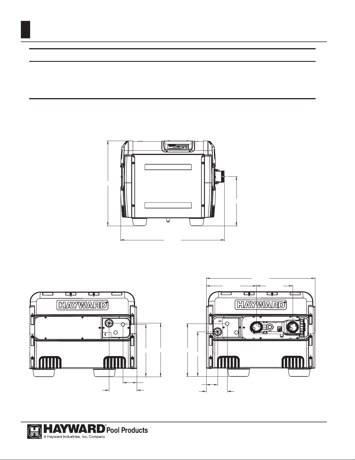
34.6cm
24.8cm
37.7cm
31.9cm
7.8cm
74.8cm
14.5cm
RIGHT
35.2cm
WIDTH
61.0cm
FRONT
37.3cm
19.1cm
9.5cm
38.3cm
LEFT
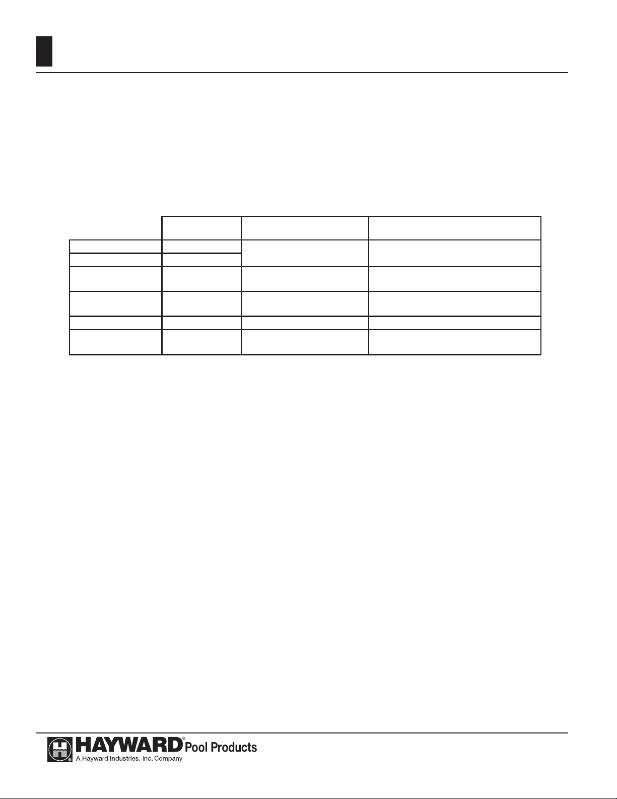
89 kg92.7 cmNatural/Propane422 MJ/hH400FDAU
75 kg71.1 cmNatural/Propane264 MJ/hH250FDAU
64 kg54.6 cmNatural/Propane158 MJ/hH150FDAU
Packaged WeightHeater WidthGas TypeHeater CapacityModel Number
USE ONLY HAYWARD GENUINE REPLACEMENT PARTS
Hayward Pool Products (Australia) Pty Ltd.
Tel: 1300 POOLS1 www.hayward-pool.com.au
11
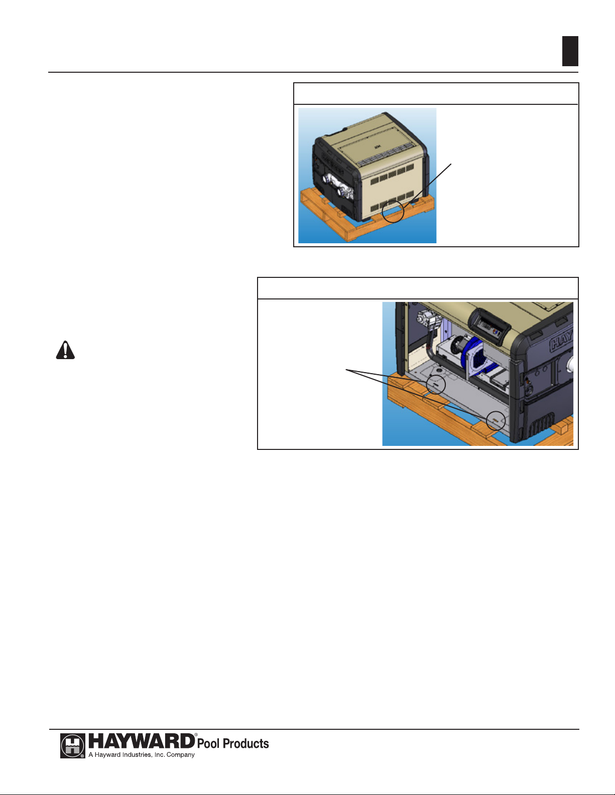
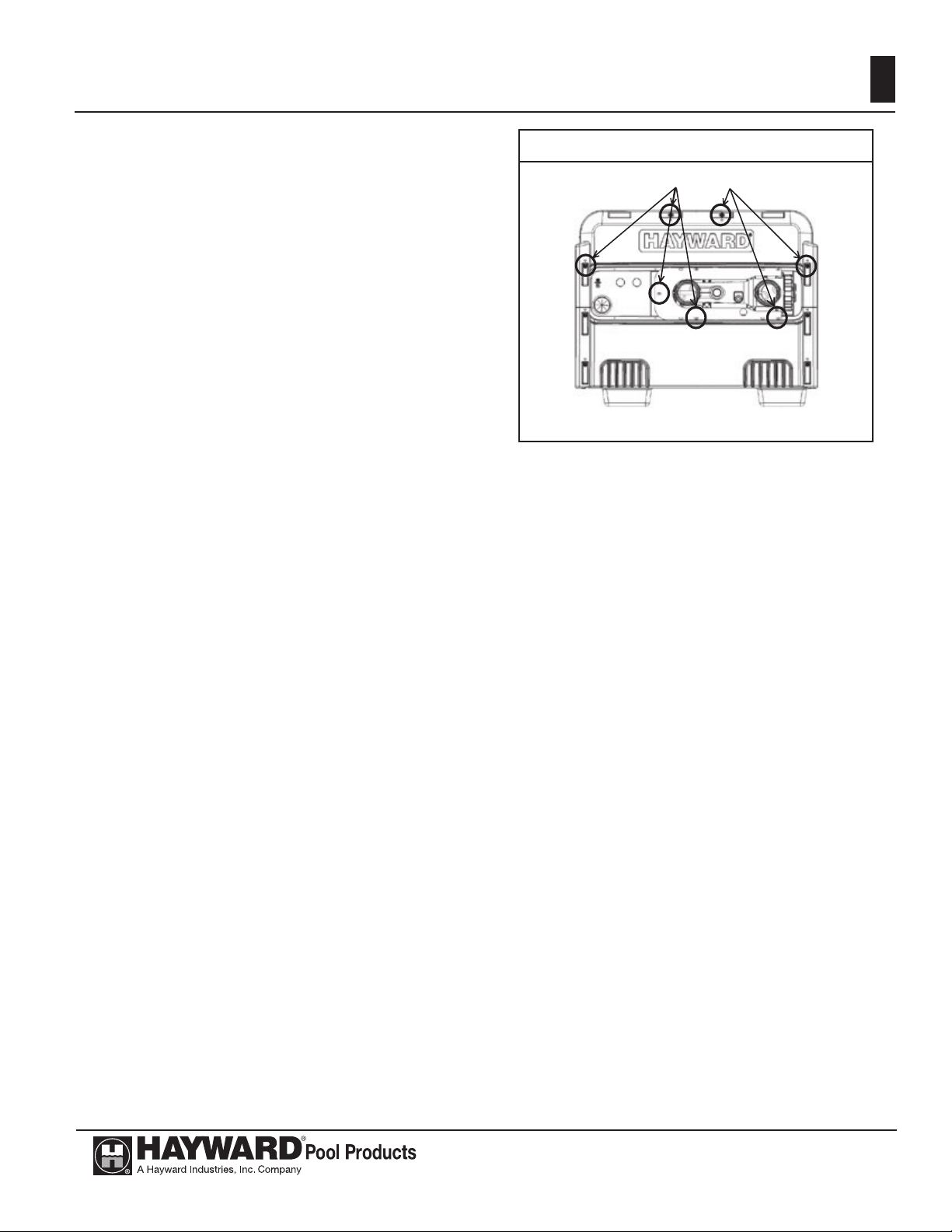
UNCRATING THE HEATER:
To remove the shipping carton from the heater:
1. Remove the corrugated carton from the
heater. The carton, top pad, bottom pad, and
the four corner posts can be recycled.
2. There are three (3) screws total used to secure the heater to the wood pallet. All three
must be removed to separate the heater from
the pallet. One (1) is located in the lower
rear of the heater as shown in Figure 1.
3. To access the other two (2) screws, open the
front access panel by removing the black
phillips-head screw. Then remove the two
(2) screws which hold the heater base pan to
the pallet as shown in Figure 2.
4. Lift the heater clear of the corrugated bottom pad and off of the pallet.
ATTENTION: Do not drop the
heater from a pickup truck tailgate
to the ground. This may damage the
heater.
Figure 1
The screw through the
rear shipping bracket
is located in this area.
Remove the screw.
It is not necessary to
remove the bracket or
the rear louvered panel.
Figure 2
Remove the (2)
shipping screws
and discard bottom
corrugated tray.
LOCATING THE HEATER:
This heater is intended for outdoor installation at an altitude below 610 M (2,000 ft) only.
Locate the pool/spa/hot tub heater in an area where leakage of the heat exchanger or connections will not
result in damage to the area adjacent to the heater or to the structure. When such locations cannot be avoided,
it is recommended that a suitable drain pan, with drain outlet, be installed under the heater. The pan must not
restrict airow.
This heater must be installed at least 1.5 meters from the inside wall of a pool (in-ground or above-
ground)/ spa/hot tub unless separated from the pool/spa/hot tub by a solid barrier.
The heater must be installed such that the location of the exhaust gas vent assembly outlet relative to
adjacent public walkways, adjacent buildings, openable windows, and building openings complies with the
National Fuel Gas Code (ANSI Z223.1/NFPA 54) and/or CAN/CGA B149 installation codes.
USE ONLY HAYWARD GENUINE REPLACEMENT PARTS
Hayward Pool Products (Australia) Pty Ltd.
Tel: 1300 POOLS1 www.hayward-pool.com.au
12
Table 1
Outdoor Installation Clearances
Heater Panel Required Clearance
Top Unobstructed
Front 24 inches (600mm)
Back 6 inches (150mm)
Water Connection Side 12 inches (300mm)
Side Opposite Water Connection 6 inches (150mm)
Outdoor installation and service clearances:
The heater must be installed outdoors such that the installation and service clearances from combustible
materials shown in Table 1 are maintained. This heater may be installed on combustible oors.
1. The heater is self-venting and does not require additional vent piping.
2. Do not install in a location where growing shrubs may in time obstruct a heater’s combustion air
and venting areas.
3. Do not install this appliance under an overhang less than (1) meter from the top of the appliance.
The area under the overhang must be open on (3) sides.
4. Do not install the heater where water spray from ground sprinkler can contact the heater. The water could splash on the controls causing electrical damage.
5. Do not install under a deck.
6. Do not install within 0.6 m of any outdoor HVAC equipment.
7. Do not install where water may run-off a roof into the heater. A gutter may be needed to protect
the heater.
8. Any enclosure around the heater must provide a combustion air vent commencing within 30 cm
of the bottom of the enclosure. The vent opening shall have a minimum free area of 645 mm
2
4,000 btu/hr input rating of all gas appliances in the enclosure. See Table 1.
per
FLOORING:
This heater may be installed on either non-combustible or combustible ooring. Ultralite™ or equivalent
concrete-over-foam HVAC pads are acceptable.
USE ONLY HAYWARD GENUINE REPLACEMENT PARTS
Hayward Pool Products (Australia) Pty Ltd.
Tel: 1300 POOLS1 www.hayward-pool.com.au
13
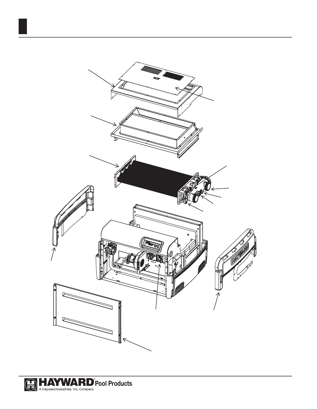
Screw Locations
REVERSIBLE WATER CONNECTIONS:
Figure 4:
This heater is designed so that it can be installed
with the water connections located on either the right
or left side. Heaters are factory-shipped with right-side
water connections. To move the connections to the left
side follow the instructions below and see Figure 4. A
trained service technician should perform these steps
before the heater is installed.
Figure 14
1. Before beginning, be aware that it is not necessary to remove the water header from the heat exchang-
er. When this procedure is complete, the water inlet will be located at the BACK of the heater. The
water outlet will be located at the FRONT.
2. Remove screws and remove both of the upper plastic heater side panels (see Figures 5). Note the
wires that pass through a hole in the heater side panel go through a split-bushing, which will allow
separation of the wires from the panel without disconnecting them.
3. Disconnect the 2 wires connecting the heater wire harness to the heat exchanger header. One is located on the water pressure switch and one is located on the temperature limit switch, both on the top
of the header. Pull these wires into the heater cabinet from the hole in the right-hand metal side panel
in the heater, and re-route them out through the left-hand metal side panel in the heater.
4. Remove countersunk screws on the heater top and remove louvered exhaust panel on heater top (see
Figure 15).
5. Remove the heater top ue cover by removing 3 screws on each side of the heater (see Figure 5).
6. Remove screws and remove rain shield assembly (see Figure 5). Note that there are screws which
hold the rain shield assembly to the heat exchanger tube sheets, which also must be removed.
7. Remove the front access panel (see Figure 5).
8. Disconnect water temperature sensor plug from the thermostat control board located inside the heater
(see Figure 5).
9. Pull the water temperature sensor wires out of the heater cabinet through the hole in the right-hand
metal side panel.
10. Remove the manual reset high limit sensing bulb from the bulbwell in the header (see Figure 5) and
pull the bulb and capillary tube into the heater cabinet and re-route them through the left-hand metal
side panel.
11. Lift and rotate the heat exchanger. Do not ip. Use care when setting the heat exchanger in place not
to damage the white sealing gaskets or combustion chamber.
12. Route the water temperature sensor wires into the heater cabinet through the hole in the left-hand
metal side panel, and re-connect to the ignition control board.
13. Re-connect the heater wire harness to the water pressure switch and temperature limit.
14. Reverse the above steps to reassemble the heater.
USE ONLY HAYWARD GENUINE REPLACEMENT PARTS
Hayward Pool Products (Australia) Pty Ltd.
Tel: 1300 POOLS1 www.hayward-pool.com.au
14
Figure 5
Top Flue Cover
Louvered
Exhaust Panel
Rain Shield Assembly
Heat Exchanger
Assembly
Pressure
Switch Port
Upper Plastic Heater
Side Panel
Thermostat
Circuit Board
Control
Temperature
Limit Switches
Drain Plug or Valve
Water temperature sensor
Manual Reset Sensing Bulb
Upper Plastic Heater
Side Panel
Front Access Panel
USE ONLY HAYWARD GENUINE REPLACEMENT PARTS
Hayward Pool Products (Australia) Pty Ltd.
Tel: 1300 POOLS1 www.hayward-pool.com.au
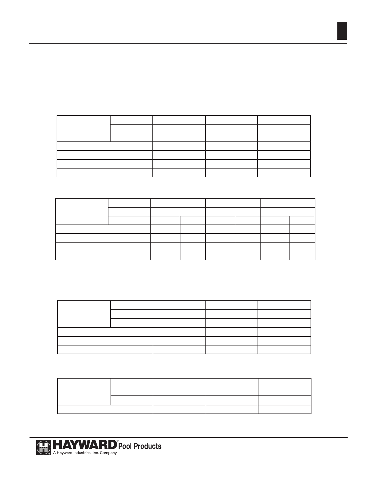
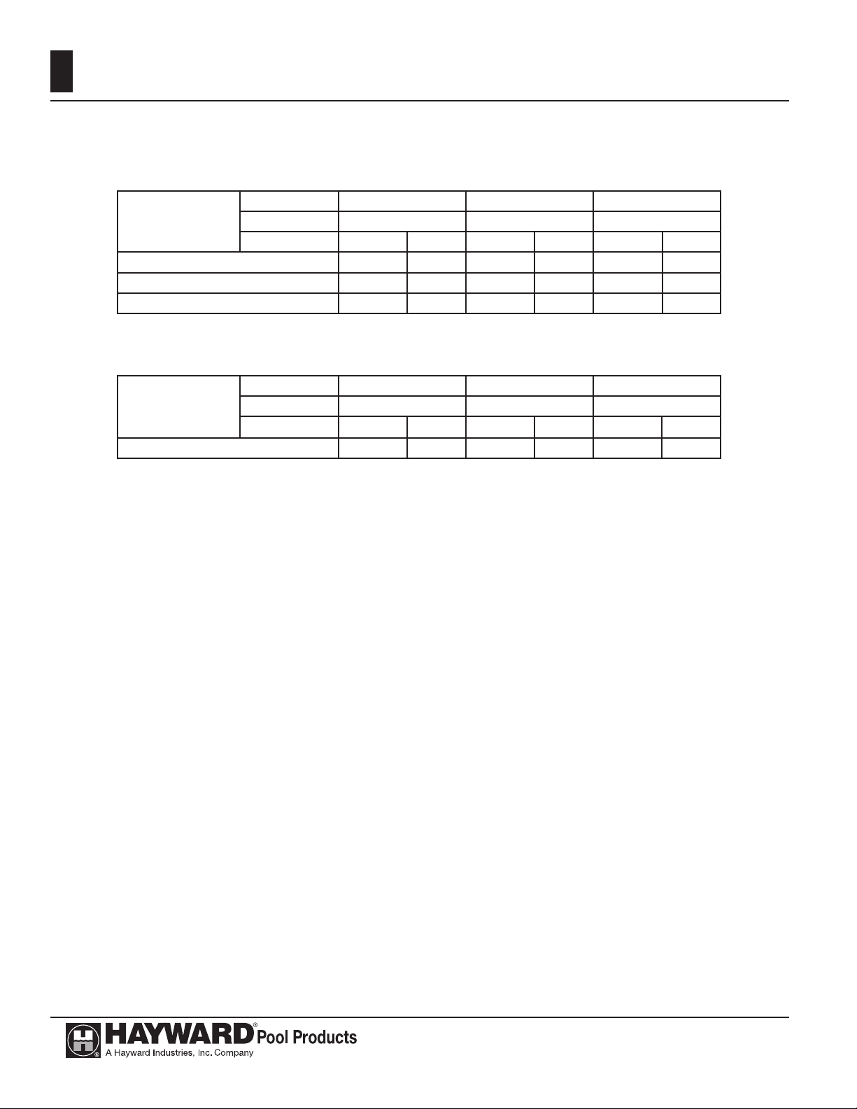
Gas Supply and Piping:
Refer to the charts below in Figure 6 for gas pipe sizing for low pressure natural gas, low pressure propane gas, two-stage natural gas and twostage propane gas systems.
Figure 6: GAS PIPE SIZE
Follow local gas codes for proper gas line material selection (copper, iron, plastic, etc.)
LOW PRESSURE NATURAL GAS PIPE SIZING: (Based upon an inlet gas pressure of 3.45 kPa or less at a pressure drop of 125 Pa)
15
Distance from Gas
Meter to Heater Gas
Valve Inlet
0 to 15 m 3/4” 1” 1-1/4”
15 to 30 m 1” 1-1/4” 1-1/4”
30 to 60 m 1-1/4” 1-1/4” 1-1/2”
60 to 90 m 1-1/4” 1-1/2” 2”
Model H150FDAU H250FDAU H400FDAU
MJ/hr input 158 264 422
Line Material Iron or Plastic Pipe Iron or Plastic Pipe Iron or Plastic Pipe
LOW PRESSURE PROPANE GAS PIPE SIZING: (Based upon an inlet gas pressure of 2.75 kPa or less at a pressure drop of 125 Pa)
Distance from Tank
Regulator Outlet to
Heater Gas Valve Inlet
0 to 15 m 3/4” 7/8” 1” 1-1/8” 1” -
15 to 30 m 3/4” 1-1/8” 1” 1-1/8” 1-1/4” -
30 to 60 m 1” 1-1/8” 1-1/4” - 1-1/4” -
60 to 90 m 1” - 1-1/4” - 1-1/2” -
Model H150FDAU H250FDAU H400FDAU
MJ/hr input 158 264 422
Line Material Iron Pipe Tubing Iron Pipe Tubing Iron Pipe Tubing
HIGH PRESSURE “2-STAGE” SYSTEMS
HIGH PRESSURE NATURAL GAS PIPE SIZING “FIRST STAGE”: (Based upon an inlet gas pressure of 13.8 kPa or less at a pressure drop of 6.8 kPa)
Distance from Outlet of
1st Stage Regulator to
Inlet of 2nd Stage
Regulator
0 to 15 m 1/2” 1/2” 1/2”
15 to 30 m 1/2” 1/2” 3/4”
30 to 45 m 1/2” 1/2” 3/4”
Model H150FDAU H250FDAU H400FDAU
MJ/hr input 158 264 422
Line Material Iron or Plastic Pipe Iron or Plastic Pipe Iron or Plastic Pipe
LOW PRESSURE NATURAL GAS PIPE SIZING “SECOND STAGE”: (Based upon an inlet gas pressure of 2.5 kPa or less at a pressure drop of 125 Pa)
Distance from Outlet
of 2nd Stage
Regulator to Heater
Gas Valve Inlet
0 to 3 m 3/4” 3/4” 3/4”
Model H150FDAU H250FDAU H400FDAU
MJ/hr input 158 264 422
Line Material Iron or Plastic Pipe Iron or Plastic Pipe Iron or Plastic Pipe
USE ONLY HAYWARD GENUINE REPLACEMENT PARTS
Hayward Pool Products (Australia) Pty Ltd.
Tel: 1300 POOLS1 www.hayward-pool.com.au
16
It is VERY IMPORTANT when installing a propane heater on a 2-stage regulation system to follow the gas line sizing chart below without exception.
HIGH PRESSURE PROPANE GAS PIPE SIZING “FIRST STAGE”: (Based upon an inlet gas pressure of 68 kPa or less at a pressure drop of 6.9 kPa)
Distance from Tank
Regulator Outlet to
Heater Gas Valve Inlet
0 to 15 m 1/2” 1/2” 1/2” 1/2” 1/2” 1/2”
15 to 30 m 1/2” 1/2” 1/2” 1/2” 1/2” 5/8”
30 to 45 m 1/2” 1/2” 1/2” 1/2” 1/2” 5/8”
LOW PRESSURE PROPANE GAS PIPE SIZING “SECOND STAGE”: (Based upon an inlet gas pressure of 2.75 kPa or less at a pressure drop of 125 Pa)
Distance from Tank
Outlet to 2nd Stage
Regulator to Heater
Gas Valve Inlet
0 to 15 m 1/2” 5/8” 1/2” 3/4” 3/4” 7/8”
Model H150FDAU H250FDAU H400FDAU
MJ/hr input 158 264 422
Line Material Iron Pipe Tubing Iron Pipe Tubing Iron Pipe Tubing
Model H150FDAU H250FDAU H400FDAU
MJ/hr input 158 264 422
Line Material Iron Pipe Tubing Iron Pipe Tubing Iron Pipe Tubing
USE ONLY HAYWARD GENUINE REPLACEMENT PARTS
Hayward Pool Products (Australia) Pty Ltd.
Tel: 1300 POOLS1 www.hayward-pool.com.au
17
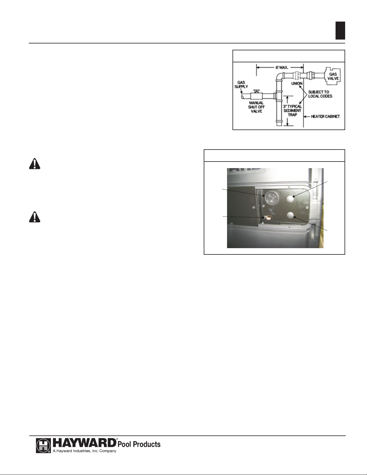
GAS SUPPLY INSTALLATION:
The heater is shipped from the factory with the gas connection
located on the left-hand side of the heater cabinet. Insert the pipe to
the gas valve through the grommet in the cabinet side (see Figure 8.)
A union should be installed outside the heater cabinet for easy removal of the gas manifold assembly during service.
An AGA approved main gas shutoff valve must be installed outside the cabinet and within 1.8 m of the heater. This valve must have
an I.D. large enough to supply the proper amount of gas volume to
the heater. See Figure 7. If BSP threads are to be used, the included
BSP to NPT adapter will be required to attach the piping to the gas
valve. NPT threads are located on the side of the adapter with
the chamfer on the inside diameter.
Figure 8. Left Side Gas and Electricity Connection
ATTENTION: Apply joint compound (pipe dope)
sparingly and only to the male threads of pipe joints.
Do not apply joint compound to the rst two threads.
Use joint compounds resistant to the action of lique-
ed petroleum gas. Do not overtighten the gas inlet
pipe or damage may result.
ATTENTION : Do not use exible appliance connectors on any gas connections unless the connector
is CSA approved for outdoor installation, is marked
with BTUH capacity (which must be equal to or
greater than the heater rated input) and the type of gas
(natural or LP).
Gas
Inlet
Bonding
lug
Figure 7. Field Gas Piping
Supply
voltage
inlet
Low
voltage
inlet
Reduction of gas supply pipe or tubing to the inlet of the heater gas valve must be made at the valve only
and must match the valve inlet size (3/4” NPT).
If more than one appliance is installed on the gas line, consult the local gas company for the proper gas
line size.
Questions on the installation of the proper gas line size can be directed to Hayward Technical Service.
NATURAL GAS:
The gas meter must have the capacity to supply enough gas to the pool heater and any other gas appli-
ances if they are on the same pipeline (Example: 225 meter = 225,000 BTUH). If doubt exists as to the meter
size, consult the local gas utility for assistance. Hayward will not be responsible for heaters that soot up due
to improper meter and gas line sizing resulting in improper gas volume.
PROPANE GAS:
All propane gas tanks must be located outdoors and away from pool/spa structure and in accordance with
the standard for storage and handling of propane gas, AS/NZS 5601.1-2010 Gas Installations and applicable
local codes. If the propane gas tank is installed underground, the discharge of the regulator vent must be
above the highest probable water level.
Propane tanks must have sufcient capacity to provide adequate vaporization for the full capacity of the
equipment at the lowest expected temperatures. Consult a propane company expert for correct sizing.
USE ONLY HAYWARD GENUINE REPLACEMENT PARTS
Hayward Pool Products (Australia) Pty Ltd.
Tel: 1300 POOLS1 www.hayward-pool.com.au
 Loading...