

Hayward H100ID1, ABG1001 Installation & Operation Manual
Installation, Operation & Service Procedures
Above Ground Pool Heater
Models H100ID1 & ABG1001
Unit must be installed outdoors only
and below an altitude of 2000 feet
FOR YOUR SAFETY
WARNING: If the information in these instructions is not followed exactly, a fire or explosion may result causing property damage,
personal injury, or death.
– Do not store or use gasoline or other flammable vapors or liquids in the vicinity of this or any other appliance.
WHAT TO DO IF YOU SMELL GAS
• Do not try to light any appliance
• Do not touch any electrical switch; do not
use any phone in your building
• Immediately call your gas supplier from a
neighbor’s phone. Follow the gas suppli-
er’s instructions.
• If you cannot reach your gas supplier, call
the fire department.
– Installation and service must be performed by
a qualified installer, service agency or the gas
supplier.
PATENT US6082993 1302507301 REV P 0811
WARNING:
The heat exchanger in your Hayward pool heater is made from the highest quality of copper materials. The premium materials
and the exacting processes used in the manufacture of the heat exchanger is state of the art in pool heater design and manu-
facture. Yet, it remains vital that the heat exchanger be protected from damaging or corrosive chemicals, insufcient water ow
or improperly balanced water chemistry. Heat exchanger damage or failure resulting from improper ow, improperly balanced
pool water or the improper addition of sanitizers into the water is NOT covered under the terms of your warranty.
The following factors are critical to heat exchanger protection. Follow these guidelines to help prevent pre-mature damage or
failure to your heater and heat exchanger.
1. WATER FLOW THROUGH HEATER
Water must be owing through the heater at the minimum rated flow rate during operation. Check that the pump is operating
and the system is lled with water and purged of all air prior to starting the heater. The minimum rated ow rate for your heater
is 20 GPM.
2. POOL/SPA WATER CHEMISTRY
The chemistry balance and mineral content of swimming pool water changes daily due to the addition of pool and sanitizing
chemicals, bather loads, rain, runoff and the amount of sun - to name a few. Improper chemistry balance and mineral content
can cause scaling and deposits to form on pool walls, in the ltration system, in the heat exchanger tubes and additionally can
promote corrosive action to all metals in the water path. Changing spa water regularly and maintaining the correct chemical
balance in your pool/spa will keep the pool/spa safe and sanitary, and will help protect the heat exchanger. Use a 4-way pool/
spa water test kit to check your water frequently (at least weekly). Use the following guidelines to help protect your heater’s
heat exchanger:
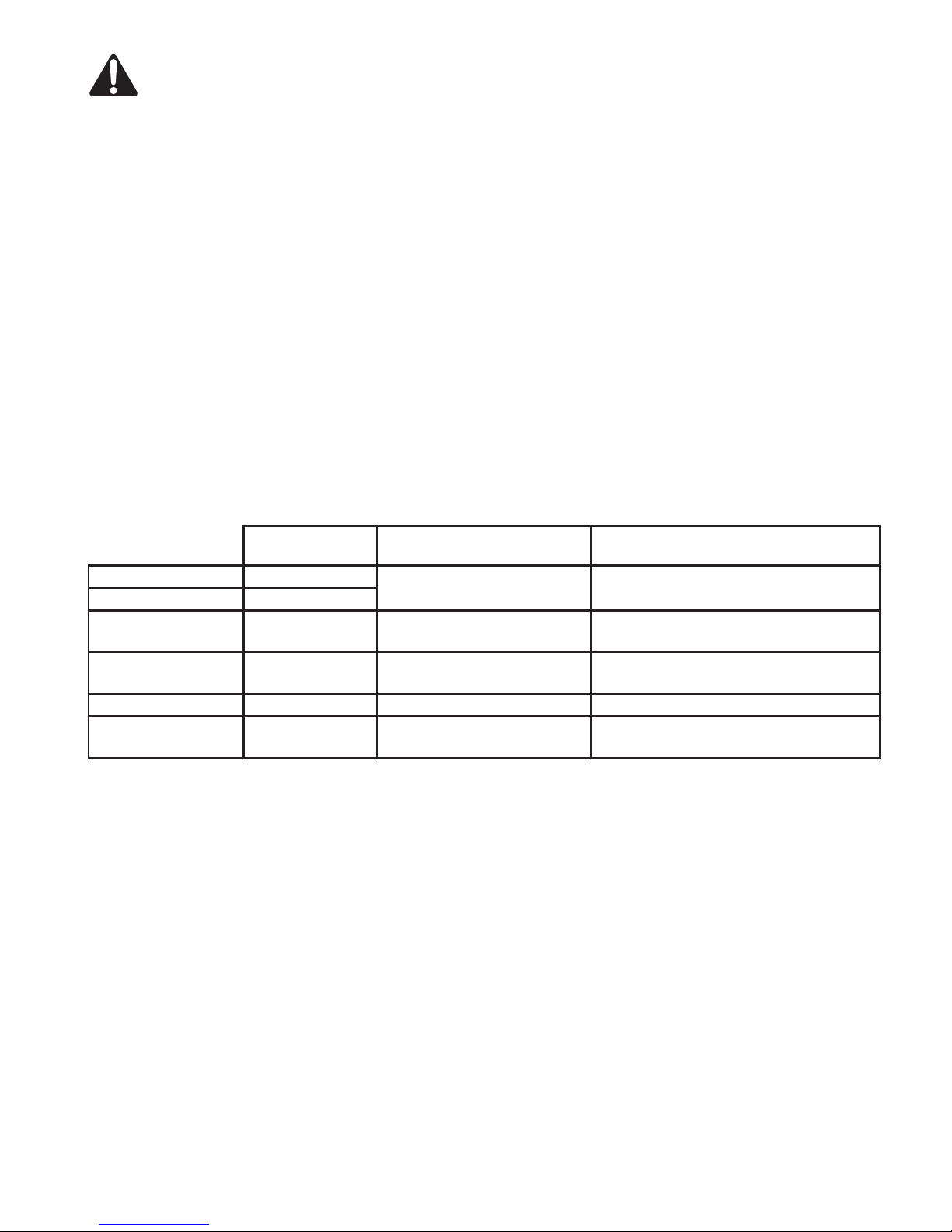
Failure to Maintain Proper Water Chemistry May Cause
Premature Heat Exchanger Damage or Failure
Recommended
Level
Chlorine
Bromine
pH
Total Alkalinity
Calcium Hardness
Salt
3. SKIMMER CHLORINATION
Placing chlorine or bromine tablets directly into the skimmer may result in high chemical concentrations owing through the
heater. DO NOT place chlorine or bromine tablets in the skimmer.
4. CHLORINATOR INSTALLATION
Chlorinators must be installed downstream of the heater, and a check valve must be installed between the heater and chlorinator to prevent high chemical concentrations from back owing into the heater.
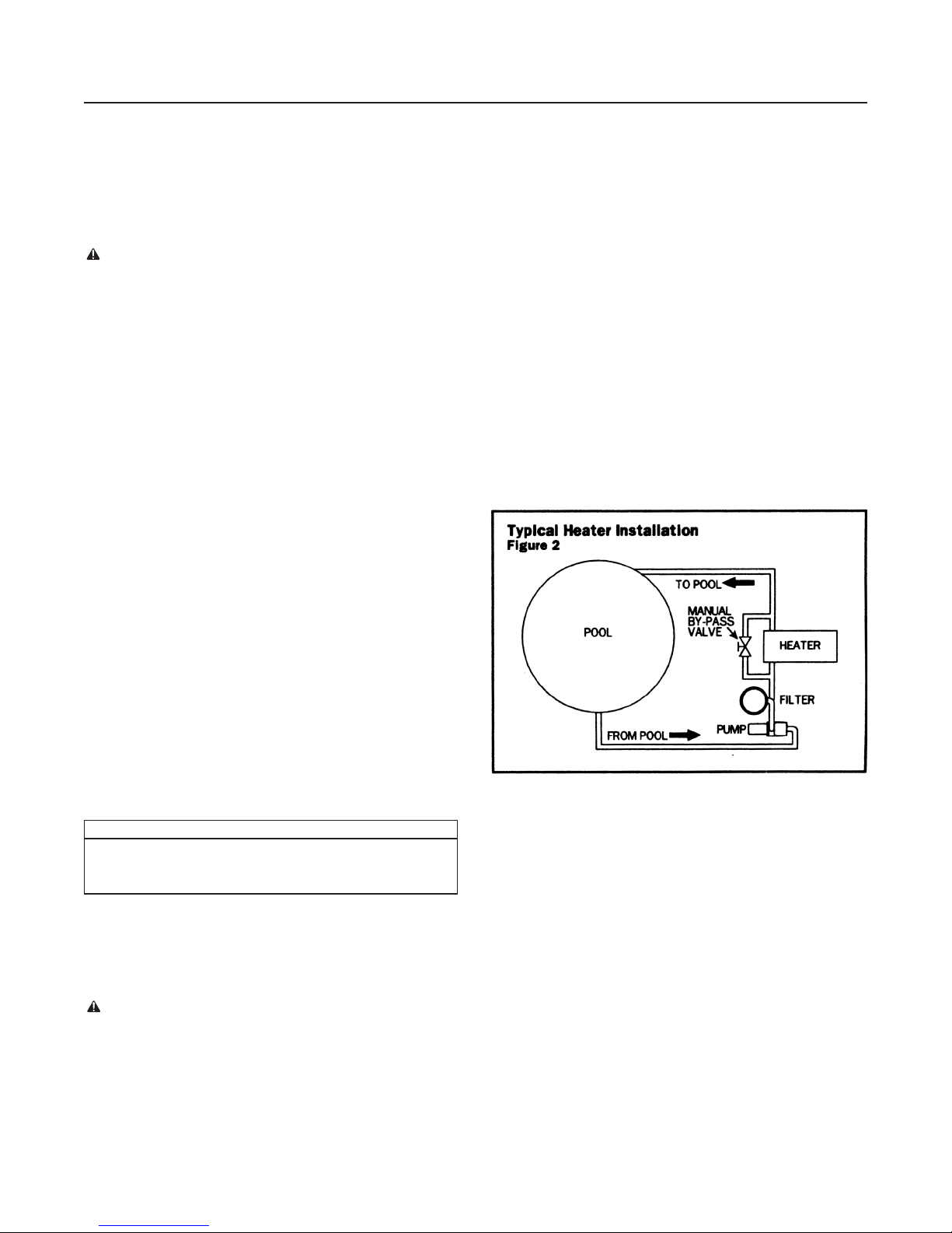
5. BYPASS
Until water chemistry is properly balanced, and if your piping has a bypass valve installed for the heater, open the bypass so
that corrosive and potentially damaging water will not ow through the heater and therefore the heat exchanger. Close the
bypass valve once the water is properly balanced. Failure to close the bypass valve when attempting to operate the heater
will result in extensive damage to the heat exchanger. Ensure water ow through the heater is restored before operating the
heater. A bypass feature is also advantageous for service needs and for the ability to remove the heater from the water path
when not heating. Refer to Figure 2 in the installation manual for further information.
1 - 3 ppm
2 - 4 ppm
7.4 - 7.6
80 - 120 ppm
200 - 400 ppm corrosive to heat exchangerscaling of heat exchanger
2700 - ppm poor salt chlorinator performancecorrosive to heat exchanger
5000
Effect of Low Levels Effect of High Levels
hazy water, algea growth,
bacteria causing infections
corrosive to heat exchanger,
swimmer irritation
corrosive to heat exchanger,
large fluctuations in pH
swimmer irritation, bleaching of clothes/hair,
corrosive to heat exchanger
cloudy water, scaling of heat exchanger,
reduced sanitizer effectiveness
scaling of heat exchanger
2
Section I. General Information
Outdoor Installations
Top - Unobstructed Right side - 10 inches
Front - 10 inches Left side - 10 inches
Back - 10 inches Bottom - Combustible floor
Important notice:
The instructions herein are intended for the use of a
qualified technician, specifically trained and experienced
in the installation of this type of heating equipment. Some
states or provinces require that installation and service personnel performing the installation be licensed. If this is the
case in the state or province where heater is located, the
contractor must be properly licensed.
WARNING: Failure to comply with the appliance
installation instructions and service instructions in this
manual may result in equipment damage, fire, asphyxiation, or carbon monoxide poisoning. Exposure to products of incomplete combustion (carbon monoxide) can
cause cancer and birth defects or other reproductive
harm.
Conformance with codes:
The heater shall be installed in accordance with all local
and state codes. The heater installation must conform to
the latest edition of the National Fuel Gas Code American
National Standard (ANSI) Z223.1 and with the requirements
of the authority having jurisdiction. Design Certification in
the United States is in compliance with ANSI Z21.56 (latest
edition).
For Canadian installations, the heater must be installed
in accordance with standards CAN/CGA B149.1 and
B149.2 – INSTALLATION CODES FOR GAS BURNING
APPLIANCES AND EQUIPMENT and/or local codes,
and if applicable, Standard CSA C22.1 – CANADIAN
ELECTRICAL CODE, Part 1.
Location of heater:
Locate the heater in an area where a leaking heat
exchanger or connection leak will not result in damage to
the area adjacent to the heater or structure.
This heater must be installed at least five feet from
the wall of an above-ground pool.
The heater shall not be installed with the top of the vent
assembly within 10 feet below or to either side of any opening into the building.
Outdoor installation only:
The following installation and service clearances must be
maintained from surfaces to provide adequate air flow to the
heater.
Figure 1
An A.G.A. Certified main gas valve shutoff must be
installed outside of the cabinet and within 6 feet of the
heater. Gas shutoff valve must have an inside diameter
large enough to supply the proper amount of gas volume to
the heater.
NOTE: Do not use flexible appliance connectors on
any gas connections unless the connector is A.G.A.
approved for outdoor Installation, Is marked with the
BTUH capacity (which must be equal to or greater than
100,000 BTUH), and the type of gas (Natural or LP) to be
used.
Propane Gas:
All Propane gas tanks must be located outdoors away
from the pool and in accordance with the standard for stor-
age and handling of propane gas, ANSI/NFPA 58 (latest
edition) and applicable local codes. If propane gas tank is
installed underground, the discharge of the regulator vent
must be above the highest probable water level.
Propane tanks must have sufficient capacity to provide
adequate vaporization for the full capacity of the equipment
at the lowest expected temperatures. Consult a propane
company expert for correct sizing.
Water piping:
This heater is designed for use with pool and spa/hot
tub water only, as furnished by municipal water distribution
systems. The warranty does not cover heater use with mineral water, sea, salt, or other non-potable waters.
Do not install any restriction in the water pipe between a
heater outlet and the pool/spa with the exception of a three-
way switching valve and associated check valve. Blockage
of water flow from heater return to pool may result in fire or
explosion causing property damage, personal injury, or loss
of life.
Plumbing connections:
Water flow rate to the pool must be between 20 and 70
gpm. If flow rate exceeds 70 gpm an external by-pass valve
must be installed. Figure 2 shows a typical heater installation.
Electrical system:
This heater is equipped with a standard 3-prong 120 volt
cordset. The plug must be inserted into a GFI protected,
watertight, outdoor receptacle rated for at least 10 amps.
The heater must be electrically grounded and bonded in
accordance with local codes, or in the absence of local
codes, with the National Electrical Code ANSI/AFPA 70.
If the heater must be hard wired, open the junction box
and disconnect the cord. Remove the cord and strain relief
and wire the heater in accordance with local codes or the
National Electrical Code.
The ignition system used to light the burners is a direct
spark system which requires 120 volt AC current as does
the blower motor. The system amp draw is 2 amps.
It is strongly recommended that the heater be supplied with a constant power source. If remote operation is
required, the heater should be controlled through the thermostat only.
Installation above or below water level:
This heater is supplied with a pressure switch factory set
at 3.0 psi. If the heater does not operate and the pressure
switch is at fault, the following procedure is recommended
to adjust the switch:
3
1. Clean filter thoroughly.
2. Set heater thermostat to highest setting.
3. Start filter pump. Make sure all air is out of water
lines and complete system is full of water.
4. Place a 5/64” allen head wrench in the adjusting
socket on the front of the switch and turn it
Section II. Installer
clockwise to increase the pressure required to close
the switch (this may be required if the heater is
installed more than 4 feet below water level).
5. To check operation, turn the pump on and off several
times. The heater should shut off immediately when
the pump is shut off.
Gas line testing:
The appliance and its gas connection shall be leak tested before placing in operation. The heater and its individual
shutoff valve must be disconnected from the gas supply
piping system during any pressure testing of that system
at test pressures in excess of 1⁄2 psig. The heater must be
isolated from the gas supply piping system by closing its
individual manual shutoff valve during any pressure testing
of the gas supply piping system at test pressure equal to or
less than 1⁄2 psig.
The gas supply line must be capped when not connected. After pressure testing, reconnect the gas piping to the
gas valve. Turn gas supply on and test all pipe and pilot tub-
ing joints for leaks. Use a soap and water solution. Bubbles
forming indicate a leak. Never use a open flame (match,
lighter, torch, etc.) as a leak could cause an explosion
or injury. Shut off gas and fix even the smallest leak imme-
diately. Be sure to leak test the main burner fittings using
the above procedure once the heater is in operation.
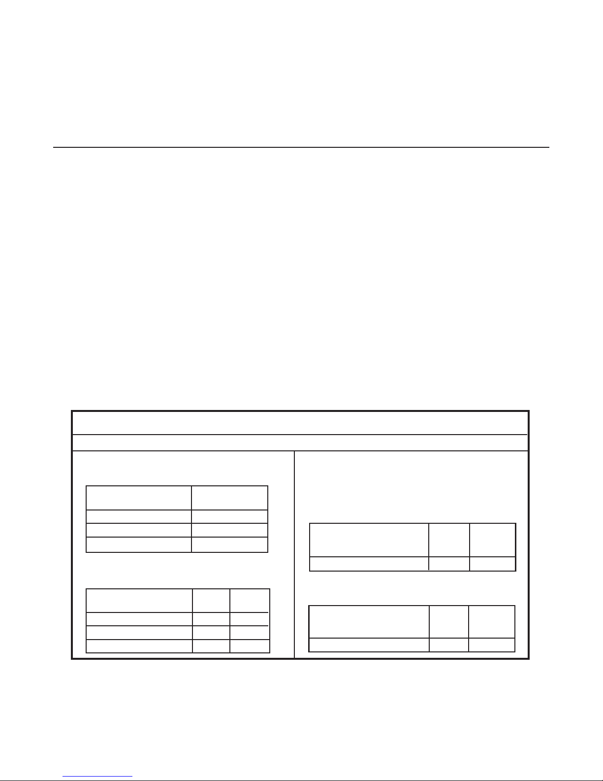
Gas pipe size:
Follow local gas codes for proper gas line material selection (copper, iron or plastic etc.)
LOW PRESSURE NATURAL GAS Pipe Sizing:
(Based upon gas pressure of 0.5 psig or less and a
pressure drop of 0.5” W.C.)
Distance from Meter Iron
(Natural Gas) Pipe
0 to 25 feet 1/2”
25 to 100 feet 3/4”
100 to 200 feet 1”
LOW PRESSURE PROPANE GAS PIPE SIZING
“SINGLE STAGE”: (Based upon gas pressure of
11” W.C. inlet pressure and a 0.5” W.C. pressure drop)
Distance from Tank Iron Tubing
(propane) Pipe
0 to 25 feet 3/8” 5/8”
25 to 100 feet 1/2” 3/4”
100 to 200 feet 3/4” 7/8”
Gas pressure test procedure:
The following gas pressure adjustments are important to
proper operation of the heater. Incorrect settings can cause
improper operation.
1. Turn pump, main gas valve and heater power on. Start
heater following lighting instructions.
2. Using a manometer, determine the inlet gas pressure.
The inlet gas pressure must not exceed 10.5” W.C.
(water column pressure) for Natural gas or 13” W.C.
for Propane gas. Exposure to higher pressures can
damage the gas control valve, causing leaks or dia-
phragm rupture. This damage could result in fire, explosion or burner overfiring leading to carbon monoxide
poisoning. The inlet gas pressure must not be below 3.0”
W.C. for Natural gas and for Propane. The heater may
fail to operate at low inlet gas pressures. If the inlet gas
pressure is too high or too low, the installer must contact
the gas supplier and request that the inlet pressure to
the heater be adjusted.
3. Using a manometer, determine the gas operating pres-
sure. Manifold pressure for both natural and propane gas
is 2.0” W.C. The gas valve is preset to operate at this
pressure, no adjustment is necessary.
Figure 4
It is VERY IMPORTANT when installing a propane heater on a
two (2) stage regulation system, to follow the gas line sizing
chart below—without exception.
HIGH PRESSURE “TWO STAGE” SYSTEMS:
MGH PRESSURE PROPANE GAS PIPE SIZING
”FIRST STAGE”: (Based upon gas pressure of 10 psig inlet
pressure at a pressure drop of 1 psi.)
Distance from outlet of Iron
1st stage regulator to Pipe Tubing
inlet of 2nd stage regulator
0 to 200 feet 1/2” 1/2”
LOW PRESSURE PROPANE GAS PIPE SIZING “SECOND
STAGE” (Based upon gas pressure of 11 inches W.C. inlet
pressure at a pressure drop of 05 inch W.C.)
Distance from outlet of Iron
2nd stage regulator to Pipe Tubing
inlet of gas valve
0 to 10 feet 1/2” 1/2”
4
 Loading...