

Page 1
T-CELL-15
GLX-CELL-15-W
NEW MENU SETTING MAY BE REQUIRED!
The T-CELL-15 and GLX-CELL-15-W are designed for pools up to 40,000 gallons. When
replacing an existing T-CELL-15 or GLX-CELL-15, no re-configuration is neccessary .
Configuration of your controller may be required before using the T -CELL-15 or GLX-CELL-15-W
chlorinator cell. Refer to the information below . Incorrect configuration will cause inaccurate salt
readings, improper operation, and possible system shutdown.
CONFIGURA TION is necessary with the following models:
• AQR (Aqua Rite - all 2009 or later) - firmware version 1.5 or later
• AQR-PRO (Aqua Rite Pro)
• PL-P-4 (Pro Logic P4)
• PL-PS-x (Pro Logic PS)
• AQ-LOGIC-P-4 (Pro Logic P4)
• AQ-LOGIC-PS-x (Pro Logic PS)
NO CONFIGURA TION is neccessary with the following models:
• AQ-RITE (Aqua Rite - 2008 and earlier) - firmware earlier than version 1.5
• AQ-RITE-XL (Aqua Rite XL)
Connecting to an AQR:
1. Slide the Main Switch to the "Auto" position.
2. Push the Diagnostic button repeatedly until "t-xx" appears on the display ("t-15" is the factory
default). If “t-15” is displayed, skip to step 4.
3. T o change cell type, slide the Main Switch from "Auto" to "Super Chlorinate" and back to "Auto".
Repeat this process until the “t-15” is displayed.
4. Push the Diagnostic button to exit.
Connecting to an AQR-PRO:
1. Access the Settings Menu by pushing the “Settings” button.
2. Push “>” until Chlor . Config is displayed, then push “+”.
3. Push “>” repeatedly until “Cell T ype” is displayed.
4. Push “+” or “-” until “T -CELL-15” is displayed.
5. Exit Settings Menu by pushing the “Info” button.
Connecting to an AQ-LOGIC-P-4, AQ-LOGIC-PS-x, PL-P-4 or PL-PS-x:
1. Enter the Configuration Menu.
2. Push “>” until Chlor . Config is displayed, then push “+”.
3. With the Chlorinator Enabled, push “>” repeatedly until “Cell T ype” is displayed.
4. Push “+” or “-” until “T -CELL-15” is displayed.
5. Exit Settings Menu by pushing the “Menu” button.
Page 2
IMPORT ANT INFORMATION
V
Regarding Extended Pool Filtration cycles, and Low Flow Rate conditions
THE AMOUNT OF CHLORINE PRODUCED BY YOUR HA YWARD/GOLDLINE SAL T CHLORINE
GENERA TING SYSTEM IS DEPENDENT ON THE LENGTH OF TIME THAT YOUR FIL TER PUMP
RUNS EVERY DA Y. SO, YOUR CHLORINA TION SETTING SHOULD BE MATCHED TO THE FIL TER
PUMP RUN TIME OF YOUR POOL.
Whether you plan to INCREASE or DECREASE the filter pump cycle on your pool, adjust the chlorination setting using
the dial on your Aqua Rite, or the up and down keys on your Aqua Rite Pro, Aqua Logic or Pro Logic system. By properly
adjusting your setting, you are preventing the over-chlorination or under-chlorination of your pool.
For example, If you plan on doubling the filter pump operating time (say from 8 hours/day to 16 hours/day), then reduce
your chlorination setting by a factor of 2 (say from 50% to 25%). If you plan to triple your filter pump operating time, then
reduce your chlorination setting by a factor of 3. Likewise, if you reduce your filter pump operating time (say from 12 hours/
day to 8 hours/day), then increase your chlorination setting by a factor of 1.5 (i.e. 12/8=1.5)
These adjustments, while necessary and important, are APPROXIMA TIONS to the actual adjustment your pool requires.
After any chlorination adjustment, monitor the pool’ s chlorine level closely for 1-2 weeks. If the readings stabilize in the 13 ppm range then you are all set—otherwise make another small adjustment (up or down) to increase or decrease the
chlorine level. Once the chlorinator is set, it is good practice to check your chlorine levels weekly to ensure operation is
normal.
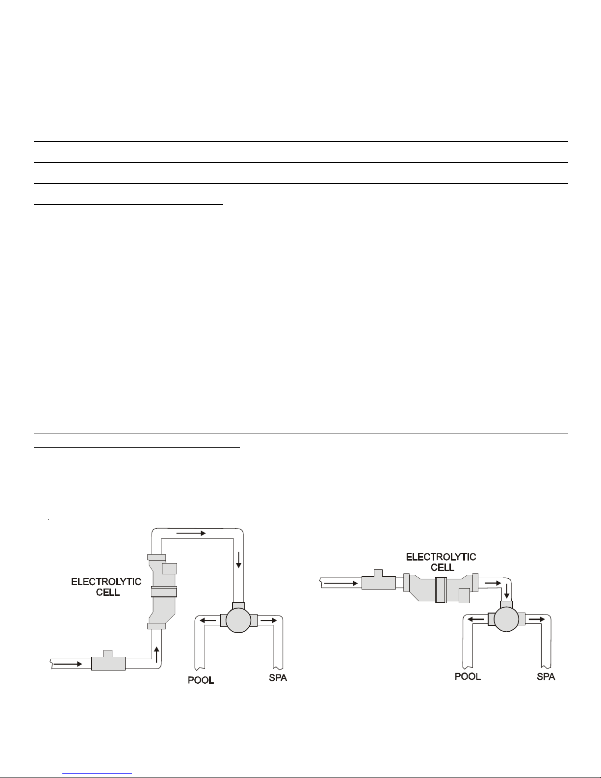
WHEN USING 2 SPEED OR VARIABLE SPEED PUMPS ON LOW SPEED, CHECK TO BE SURE YOUR SAL T
CELL IS RECEIVING ADEQUATE FLOW. Low flow conditions can result in insufficient water in the cell causing
inefficient chlorine production. As a precaution, the cell can be installed vertically or in an inverted manner (see illustration)
to keep it flooded with water .
ertical Installation
Desired installation configurations when using 2 speed or variable speed pumps.
Inverted Installation
092409A RevB
 Loading...