

Hayward CAT 4000 Owner's Manual
\
USE ONLY HAYWARD GENUINE REPLACEMENT PARTS
Hayward Pool Products
620 Division Street, Elizabeth NJ 07207
www.hayward.com
CAT 4000
Water Quality Controller
Owner’s Manual
092431A RevE
CAT-4000
Contents
Introduction............................................2
Installation..............................................4
Pool Chemistry........................................7
Conguration..........................................7
System Maintenance.............................24
Network Communications.....................25
Troubleshooting....................................29
Warranty...............................................34
®

USE ONLY HAYWARD GENUINE REPLACEMENT PARTS
1
IMPORTANT SAFETY INSTRUCTIONS
When using this electrical equipment, basic safety precautions should always be followed, including the following:
• READ AND FOLLOW ALL INSTRUCTIONS
• WARNING: Risk of Electric Shock. Connect controller only to a grounding type recep-
tacle protected by a ground-fault circuit interrupter (GFI). CAT Controllers recommends
installation to a dedicated GFI circuit breaker performed by a licensed electrician.
• WARNING: Disconnect power before servicing. Other than the fuses, there are no user
serviceable parts inside the controller.
• WARNING: All power cords should be inspected frequently. Any damaged power cords
must be replaced immediately to reduce the risk of electric shock. Never operate a
controller without functional flow protection.
• WARNING: Installation requires a properly located GFI protected receptacle. Never use
an extension cord for electrical connections to the controller.
• WARNING: Always mount controller in a safe area not subject to damage by moving
objects. Never bury controller power cords.
• WARNING: Any person using, adjusting, or monitoring the controller must be at least 18
years of age and be familiar with these instructions and the contents of this manual.
• WARNING: Always take and record manual water chemistry readings in conformance
with Health Department requirements. Although automated controllers are a great aid in
maintaining healthy water quality, controllers are not a substitute for manual water testing with an accurate test-kit.
• WARNING: Always read and become familiar with Material Safety Data Sheets (MSDS)
and safe handling instructions for all chemicals used with the controller.
• CAUTION: The automatic controller should not be installed where it is accessible to the
public.
USE ONLY HAYWARD GENUINE REPLACEMENT PARTS
2
Introduction
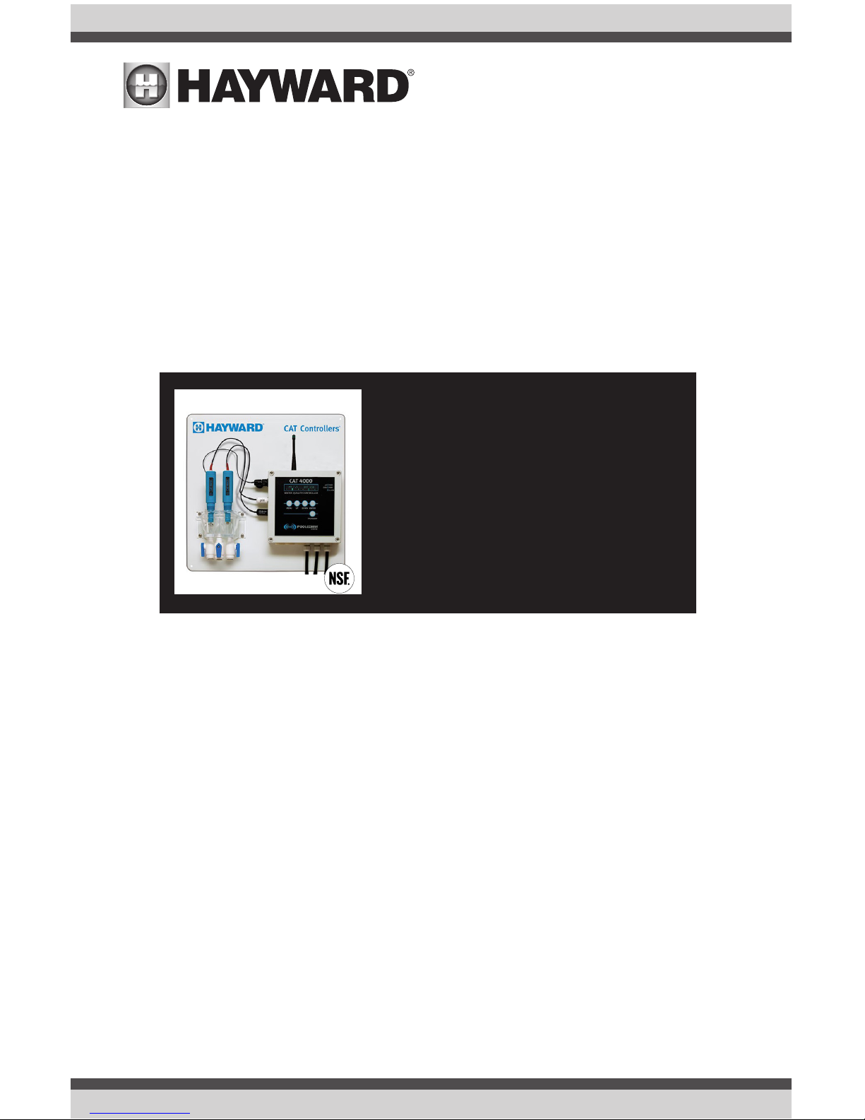
Description
The CAT 4000 revolutionizes the manner in which water quality can be monitored and maintained.
A pool operator typically checks, records and adjusts pool or spa water chemistry hourly at best.
The CAT 4000 continuously samples pH and sanitizer activity, adjusting the feeding of chemicals
on a basis proportional to the demand. Hourly water quality readings are sent along with any
alarms or service requests through a wireless network to the POOLCOMM web server for remote
monitoring and management through any internet connection. NOTE: The POOLCOMM website is
a subscription based service. Monthly charges apply.
From the website, the subscriber can monitor water quality, print charts, graphs and logs, change
controller settings, and designate contacts for outbound notification via email, cell phone or PDA.
Optional digital flow and level sensors are available to monitor flow rate, chemical storage tank
levels, and even automate water level control.
The results include elimination of “human error”, accurate and reliable maintenance of chemical
levels twenty-four hours a day, compliance with Health Department operating standards, reduced
burden on operating staff, and a reduction of chemical usage and costs. The CAT 4000 controller and POOLCOMM water quality management website together provide unprecedented control,
access and documentation.
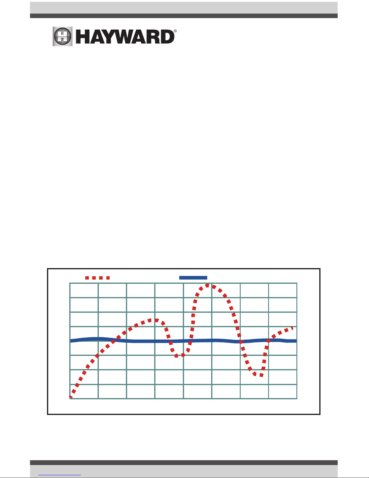
The following graph compares typical chlorine levels when chemistry is adjusted manually versus
automatically with the CAT 4000 controller:
Manual Control
HCC Automated Control
CL2
3.5
3.0
2.5
2.0
1.5
1.0
0.5
0.0
10:00 11:00
12:00
1:00 2:00
3:00
4:00
5:00
Time

USE ONLY HAYWARD GENUINE REPLACEMENT PARTS
3
What’s Included
Description
The following is a description of the components incorporated in a typical CAT 4000 wireless water
quality control system:
The Professional-Series pH Sensor samples water from the filtration system and sends signals to
the controller indicating the acidity of the water. The ideal pH range for pools and spas is 7.4 - 7.6.
The CAT 4000 controller is preset from the factory to maintain pH 7.5. If pH is maintained below
7.4 (too acidic), eye irritation, corrosion of equipment, and damage to the pool or spa surface can
occur. If pH is maintained above 7.6 (too alkaline), sanitizer activity is reduced, water may become
cloudy, and eye irritation may result.
The Professional-Series ORP Sensor samples water from the filtration system and sends signals
to the controller indicating the oxidation-reduction potential (redox) of the water. ORP is an actual
measure of sanitizer activity (chlorine, bromine, ozone, etc.) and bacteriological water quality rather
than an expression of chemical residual levels. The CAT 4000 controller is preset from the factory
to maintain ORP at 650 millivolts.
The Flow Sensor monitors the rate of flow across the pH and ORP sensors and signals the controller to disable automated chemical feeding during periods when the filtration system is off or low
recirculation flow is detected.
The Flow Cell provides a convenient location for mounting the pH, ORP and Flow sensors while
ensuring ideal hydraulic conditions to maximize sensor performance and life.
The CAT 4000 Controller scans and interprets the signals from the pH, ORP, flow, and optional
digital flow-rate and level sensors, displays water quality readings and alarms in alphanumeric
format, and activates chemical feeders in proportion to demand to maintain pH and ORP setpoint
levels.
The controller incorporates audible and visual safeguard alarms for out of range conditions and
menu-driven control of setpoints, alarms, and a host of advanced features. The CAT 4000 controller also features an internal transceiver for wireless transmission of data between the controller
and POOLCOMM website.
The Level Sensors (optional) provide signals to the controller indicating low pH chemical tank level,
low ORP tank level, and low water level.
The Digital Flow Sensor (optional) provides a flow rate to be displayed by the controller and an
alarm indication when filter maintenance is required.
Package Contents:
(1) CAT 4000 Wireless Water Quality Controller
(1) PVC Backboard with Mounting Holes and Stainless Hardware
(1) Professional Series pH Sensor with 24” Cable and BNC Connector
(1) Professional Series ORP Sensor with 24” Cable and BNC Connector
(2) Sensor Storage Containers
(1) Injection Molded Flow Cell

USE ONLY HAYWARD GENUINE REPLACEMENT PARTS
4
(3) 1/4” NPT x 3/8” Tubing True-Seal Ball Valve
(1) Flow Switch with 24” Cable and Specialty Connector
(2) BNC Connector Protective Covers (Remove to Connect Sensors)
(1) 30’ Roll, Blue Poly Installation Tubing (3/8” OD)
(2) 1/4” NPT x 3/8” Tubing True-Seal Connectors
(1) CAT 4000 Quick Reference Guide
NOTE: Before commencing installation, please confirm that items listed above have been included.
Please report any shortages immediately to the factory.
What You Will Need
The following tools are recommended for installation:
• Drill (Cordless preferred)
• 3/8” Drill Bit
• 1/4” NPT (National Pipe Tapered) Tap
• Masonry Drill Bit & Anchors (if required)
• 13/16” Wrench or Channel-Lock Pliers
Installation
Installation Procedure
The key to a successful flow cell installation is in the plumbing. A pressure differential is required to
allow clean, untreated water to pass through the cell and across the sensors. We recommend using
the enclosed tubing and fittings to create a pressure-suction “loop” line.
Follow the directions below for installation and refer to the Installation Diagram on page 6.
1. Turn off heater, chemical feeders, pump, and any other related equipment. Relieve pressure
from filtration system.
2. Select a convenient mounting location for the controller unit which will meet the following
criteria:
• Facilitates a combined (influent and effluent) maximum tubing run of 30’
• Located a minimum of ten feet from pool or spa
• GFI protected power source available
• Easily accessible to pool or spa operator
• Away from corrosive materials and physical hazards
3. Securely mount PVC Backboard on vertical wall.
4. Drill and tap a 1/4” NPT port at a location just downstream of the filter, but upstream from
any chemical injection point. Install a tubing connector, and run flex tubing to the influent
flow cell port.
5. Drill and tap a 1/4” NPT port at a location subject to vacuum or reduced pressure. Install the
remaining tubing connector and run flex tubing to the effluent flow cell port.
6. Cut a 3” length of flex tubing and insert into the sample stream port.
USE ONLY HAYWARD GENUINE REPLACEMENT PARTS
5
7. Remove pH and ORP sensors from the plastic storage bottles and save bottles and storage
fluid for future use. Thread sensors into flow cell.
8. Remove BNC protective covers from left side of controller unit and store for future use.
These covers protect the controller unit from electrostatic discharge (ESD) and should be
used whenever handling or transporting the controller unit.
9. Connect the pH, ORP and Flow sensor cables to the controller unit as labeled. Sensor cables
are constructed from a specialized material - never cut or splice.
10. If new or additional chemical feeders are to be used with the controller, install according to
manufacturer’s instructions at this time.
11. Connect chemical feeders to the controller as labeled (See diagram on following page).
12. Check all electrical and mechanical connections. Resume filtration system operation and
check for any leaks.
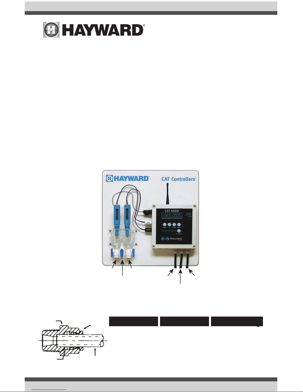
Working with Tru-Seal Fluid Connections for a Fast, Professional Installation (See diagram below).
Body
Collet
TubingO-Ring
Prepare Tubing: Insert Tubing
To Release Tubing:
Cut tubing squarely
and remove any
burrs. Mark tubing
3/4” from end. This
is the insertion mark.
Insert tubing straight
into fitting until it
bottoms out and
insertion mark is no
longer visible.
Push collet toward
fitting body and pull
on tubing to release.
Repeat steps 1 and 2
to reuse fitting.
Influent
Sample
Stream
Effluent
pH Feed
ORP Feed
Power
Supply
USE ONLY HAYWARD GENUINE REPLACEMENT PARTS
6
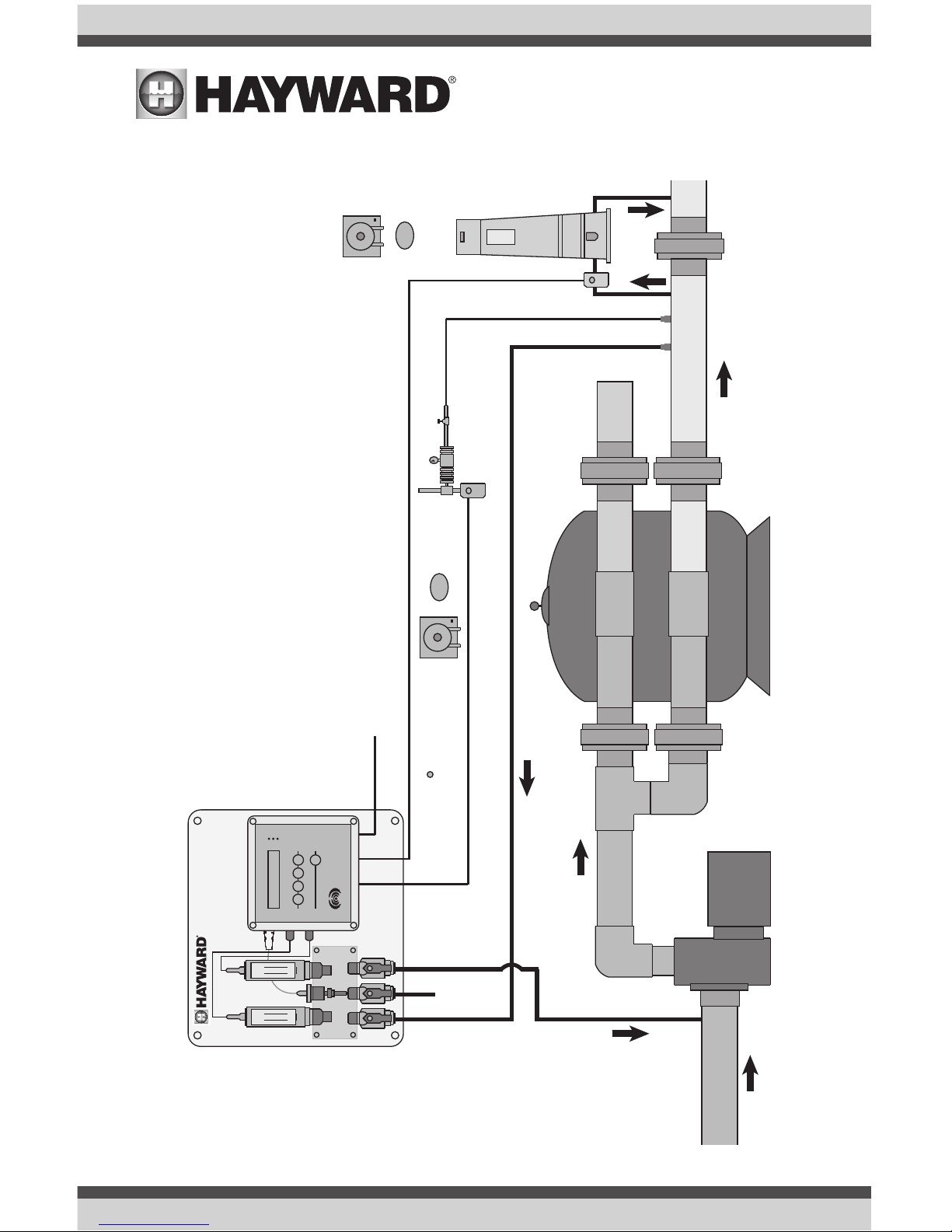
Typical Cat 4000 Installation Diagram
Flow
Main Drain
and Skimmer
Flow
Flow
Flow
Flow Cell / Flow Sensor Bypass Line
Solenoid
Flow
Pressure
Differential
Solenoid
CAT CO2
pH Control
Erosion
Feeder
or
or
Chemical
Pump
Chemical
Pump
pH Feed Output
Power Cord
ORP Feed Output
Influent
(to Return Line)
Effluent
(to Suction)
CAT 4000
SYSTEM
CAT Controllers
SUCTION LINE
PUMP
FILTER
WASTE
RETURN LINE
Sample
Stream
MENU UP DOWN ENTER
TRANSMIT
CAT 4000
POOLCOMM
ENABLED
pH
Cl/Br
FEED
FEED
ALARM
WATER QUALITY CONTROLLER
CAT PRO25
ORP
Sensor
CAT PRO15
pH
Sensor
pH
ORP
Flow
pH
ORP
USE ONLY HAYWARD GENUINE REPLACEMENT PARTS
7
Pool Chemistry
Now that your new controller has been physically installed, water chemistry should be tested and
adjusted prior to initiating automated control of the pool or spa. Confirm that your pool or spa water
conforms to the following ranges before powering on and setting up the CAT 4000.
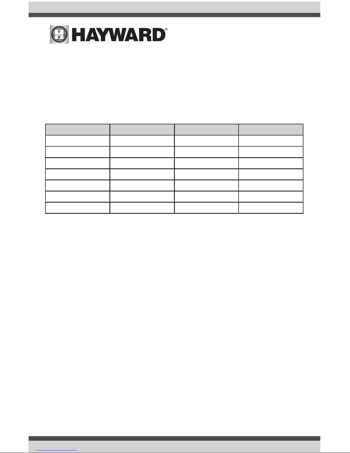
The table below indicates generally accepted guidelines. Always maintain water chemistry according to standards set by your local or State Health Department.
Test Minimum Ideal Maximum
pH 7.2 7.5 7.8
Free Chlorine (PPM) 1 2 3
Bromine (PPM) 2 3 4
Cyanuric Acid (PPM) 0 - 100
ORP (mV) 650 - -
Total Alkalinity 80 - 120
Calcium Hardness 200 - 400
All CAT water quality controllers maintain sanitizer levels (chlorine, bromine, ozone, etc.) based
on ORP. Although ORP is a superior index of water quality compared to part per million sanitizer
residual levels, factors such as pH, cyanuric acid concentration and total dissolved solids can affect
sanitizer residual readings relative to ORP.
CAT Controllers recommends establishing desired pH, sanitizer residual, calcium hardness, total
alkalinity, temperature and cyanuric acid levels prior to initiating automated control of the pool or
spa. The ORP setpoint will need to be changed periodically as described later in this section if the
goal is to provide consistent sanitizer residual levels rather than consistent control of ORP.
Configuration
Overview
The CAT 4000 features a bright, menu-driven vacuum-fluorescent display which makes setup and
programming simple in any lighting conditions. The menu structure is divided into two sections; the
Operating Menu is intended for the end user to manage settings which are accessed on a frequent
basis, while the Configuration Menu is used to set up advanced features which truly customize the
controller to meet the individual requirements of the application.
The keypad provides intuitive access to the controller functionality as described on the following
page.
USE ONLY HAYWARD GENUINE REPLACEMENT PARTS
8
MENU: Used to enter menu mode and to navigate back within the menu structure.
UP: Used to increase values and to navigate vertically up within the menu structure.
DOWN: Used to decrease values and to navigate down within the menu structure.
ENTER: Used to select or confirm a menu item.
TRANSMIT: Sends a Service Request alarm and current data to the POOLCOMM web server.
Basic Configuration Options
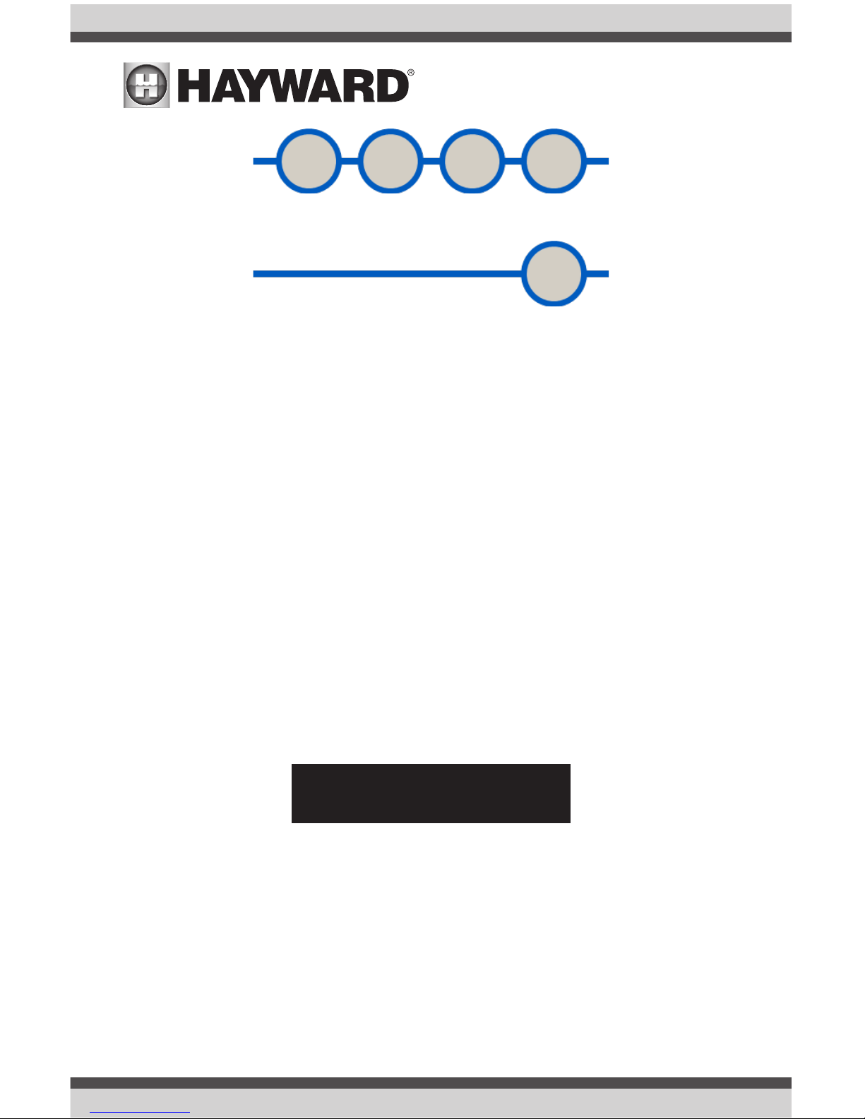
Normal Operating Mode:
During normal operating mode, the display will indicate sensed pH, ORP, Flow Rate (with optional
digital flow sensor) and a status line which alternates between:
a) “System OK” or a list of any alarm conditions
b) A graph indicating sensed pH and ORP vs- setpoint values
The following is a typical display during normal operating mode:
To Change The Brightness Of The Display:
The display intensity can be changed to accommodate comfortable viewing in a variety of lighting
circumstances. While in normal operating mode:
Press UP to increase display intensity.
Press DOWN to decrease display intensity.
MENU UP DOWN ENTER
TRANSMIT
pH 7.5 ORP 650
System OK

USE ONLY HAYWARD GENUINE REPLACEMENT PARTS
9
To Enter The Operating Menu:
The operating menu contains selections which are likely to be changed on a routine basis, and
therefore are easily accessed. While in normal operating mode:
Press MENU.
The following will be displayed:
To Change The pH Setpoint:
The CAT 4000 is programmed at the factory with a default setpoint of pH 7.5. CAT Controllers
considers this to be ideal for pool and spa applications. The following steps enable the selection of
a different setpoint. While in normal operating mode:
Press MENU.
Select pH setpoint by pressing ENTER.
The current pH setpoint will be displayed:
Press UP or DOWN to select the desired pH.
Press ENTER to save your selection.
The controller will automatically return to normal operating mode in 10 seconds.
To Calibrate pH:
The CAT 4000 is far more accurate than most liquid test standards, but pH calibration is necessary to match manual water testing results, compensate for a depleted or unclean pH sensor, and
confirm proper operation of the system. While in normal operating mode:
Press MENU.
Press DOWN to find the pH Calibrate menu item.
Press ENTER to select pH Calibrate.
The sensed pH value as currently calibrated will be displayed:
Press UP or DOWN to match your known good standard.
Press ENTER to save your selection.
The controller will automatically return to normal operating mode in 10 seconds.
pH Calibrate
7.5 pH
Operating Menu
pH Setpoint
pH Setpoint
7.5 pH

USE ONLY HAYWARD GENUINE REPLACEMENT PARTS
10
To Select pH Feed Mode:
The CAT 4000 is programmed at the factory to operate in automatic feed mode as the default setting. Other pH feed mode selections include off (disabled), and manual on for a fixed interval up to
25 minutes after which automatic feed will resume. While in normal operating mode:
Press MENU.
Press DOWN to find the pH Feed Mode menu item.
Press ENTER to select pH Feed Mode.
The current pH Feed Mode will be displayed:
Press UP or DOWN to find the desired selection.
Press ENTER to save your selection.
The controller will automatically return to normal operating mode in 10 seconds.
The “Off” (disabled) mode is useful when servicing pH feed equipment, or if pH chemical supply
has been depleted.
The “Manual On” mode allows constant chemical feed for a fixed interval of up to 25 minutes. This
feature is useful when adding extra chemicals is desired and during initial balancing of the water.
NOTE: Always disconnect chemical feeder power cords prior to performing any electrical service.
To Change The ORP Setpoint:
The CAT 4000 is programmed at the factory to maintain ORP at 650 mV by default. This is the
generally accepted world standard for safe drinking water. In order to maintain a given chlorine or
bromine residual in conformance with Health Department standards for a particular body of water,
perform the following:
Check and balance pH, calcium hardness and total alkalinity. Manually feed chlorine or
bromine to desired ppm residual. Note the displayed ORP value. This will be used as the
setpoint. While in normal operating mode:
Press MENU.
Press DOWN to find the ORP Setpoint menu item.
Press ENTER to select ORP Setpoint.
The current ORP setpoint will be displayed:
Press UP or DOWN to select the setpoint noted above.
Press ENTER to save your selection.
The controller will automatically return to normal operating mode in 10 seconds.
pH Feed Mode
Automatic Feed
ORP Setpoint
650 mV
 Loading...