

Page 1
IS0250 Rev D
™
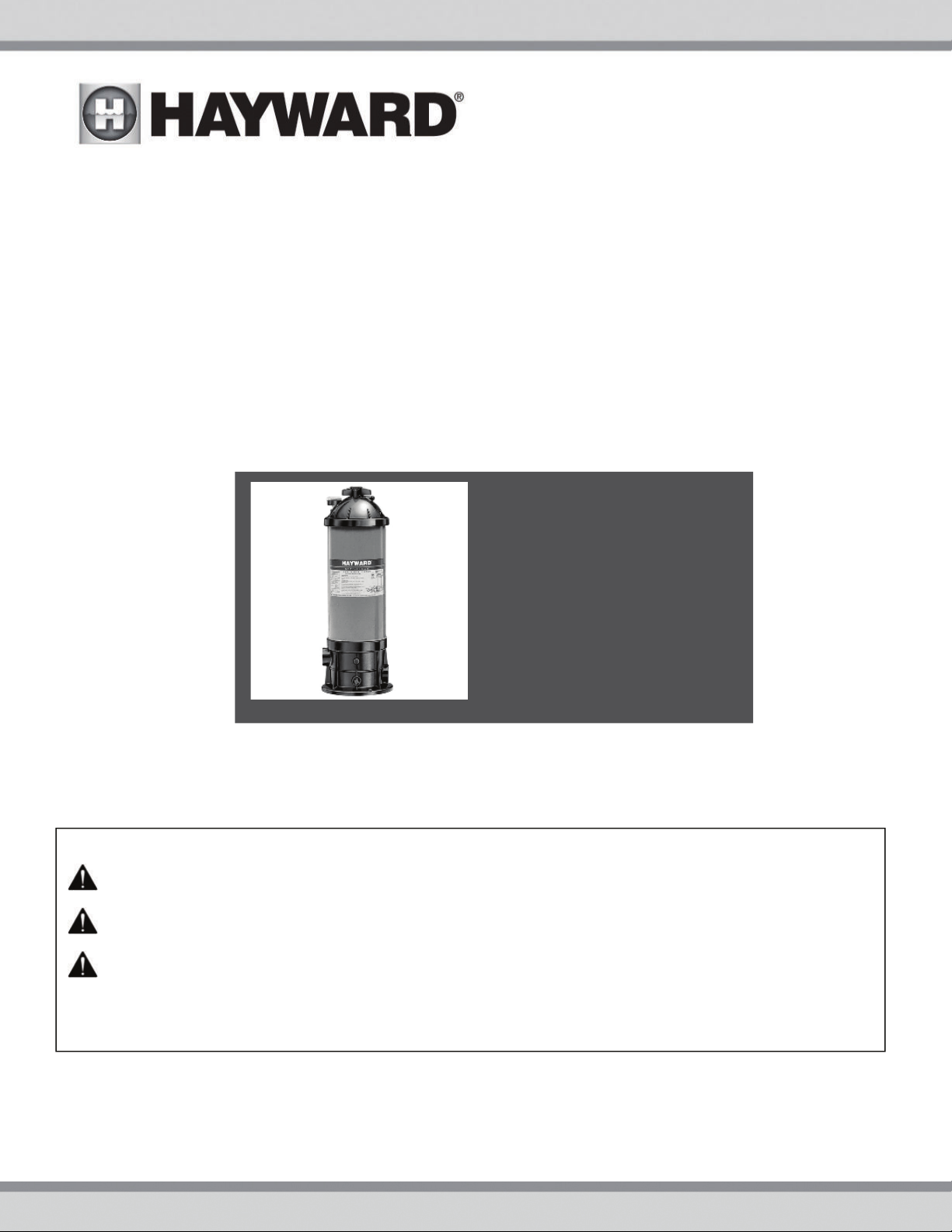
StarClear
CARTRIDGE FILTER
Owner’s Manual
Contents
Warnings………………………………2
Introduction……….…………..…..…4
Installation……….……………..….…4
Replacement Parts………..….…….6
Warranty………………………………….7
Registration ………………………….…8
MODELS: C250, C500
IMPORTANT SAFETY INSTRUCTIONS
Basic safety precautions should always be followed, including the following: Failure to follow instructions
can cause severe injury and/or death.
This is the safety-alert symbol. When you see this symbol on your equipment or in this manual, look for
one of the following signal words and be alert to the potential for personal injury.
WARNING warns about hazards that could cause serious personal injury, death or major property
damage and if ignored presents a potential hazard.
CAUTION warns about hazards that will or can cause minor or moderate personal injury and/or property
damage and if ignored presents a potential hazard. It can also make consumers aware of actions that are
unpredictable and unsafe.
NOTICE label indicates special instructions that are important but not related to hazards.
The
Hayward Pool Products
620 Division Street, Elizabeth, NJ 07207
Phone: (908) 355-7995
www.hayward.com
USE ONLY HAYWARD GENUINE REPLACEMENT PARTS 1
Page 2
R
t
R
s
a
t
u
e
Wbeap
h
e
ngu
n
R
u
R
a
R
a
T
d
o
p
e
g
n
n
m
a
c
h
a
b
e
w
v
e
e
e
c
r
i
i
y
o
e
o
w
v
u
e
p
s
n
o
e
a
c
e
o
s
O
o
n
m
n
a
e
e
a
t
e
n
p
c
c
e
s
e
m
f
r
g
s
m
t
m
n
I
i
e
A
r
w
m
o
a
r
n
y
a
o
e
e
m
o
m
a
m
o
o
o
e
o
.
e
d
a
c
p
a
f
a
b
e
r
o
A
N
t
m
.
t
b
o
c
m
w
s
h
m
a
e
p
a
e
t
t
n
m
r
s
t
c
t
m
m
t
v
n
d
d
w
t
o
g
u
i
s
o
i
s
w
s
s
n
m
r
p
e
p
i
e
t
e
R
r
n
a
k
s
a
i
i
E
o
.
n
s
e
e
u
u
t
o
s
l
s
D
o
g
y
e
e
n
n
a
f
u
i
r
p
u
h
t
o
e
r
f
e
m
o
e
o
p
n
t
t
e
i
o
s
r
e
d
WA
NING
-
Re
follow ins
Suction in
severe inju
Hair Entra
Limb Entr
cracked, m
Body Suc
Eviscerati
sump or s
disembow
Mechanic
opening of
suction o
material c
replaced
being use
on this pro
positioned
WA
WAR
o
o D
o D
o T
o N
o R
o I
o I
WA
WA
WA
CAU
ructions can
NING
– Suc
uction outlets
ry and/or deat
pment
- Hair c
pment
- A lim
issing, or not s
ion Entrapm
on/ Disembo
ction outlet co
lment.
l Entrapmen
a suction outl
NING
ual suction fitt
ual suction fitt
ever use Pool
- To R
hen outlets ar
installed. Su
art, as measu
e maximum s
place damag
addition two
idelines, follo
stallation of a
NING
–
Fail
tlets can resu
NING
–
Fail
n result in an
NING
–
t least every t
ION
as means of
uct. Closely
to prevent chil
Suc
–
Com
d and foll
ause severe i
tion Entrap
and/or suctio
due to the fol
n become ent
inserted into
ecurely attach
nt
- A negative
elment
er which is, d
- There is pot
t cover resulti
duce the ris
small enough
tion outlets in
ed from near
ngs shall be pl
ngs shall not b
stem flow rate
r Spa if any su
d, broken, cra
r more suction
all National,
acuum releas
re to remove
lt in an increa
ure to keep su
increase pot
tion outlet co
n years or if
onents such
access to the
upervise child
dren from usin
w all inst
jury and/or d
ent Hazard.
outlet covers
lowing entrap
ngled in sucti
an opening of
d can result in
pressure appli
- A n
gative pressu
maged, broke
ntial for jewelr
g in mechanic
k of Entrapm
to be blocked
the same plan
oint to near po
aced in such l
e located on s
shall not exce
tion outlet co
ked, missing,
outlets per pu
State, and Loc
or vent syste
pressure test
e potential f
ction outlet c
ntial for sucti
ponents hav
ound to be da
as the filtrati
pool by young
en at all times
them as a m
uctions
eath.
hich are, da
ent hazards:
n outlet cover
suction outle
a mechanical
d to a large p
e applied dire
, cracked, mis
, swimsuit, ha
l entrapment.
in
ent Hazards:
by a person, a
e (i.e. floor or
int.
cations and di
ating areas or
d 6 ft/sec in t
ponent is da
r not securely
p installed in
l codes applic
, which reliev
plugs and/or
r suction entr
mponents cl
n entrapmen
a finite life,
maged, broke
n system, pu
children. To
Components
ans of access
his owner’s m
aged, broken,
sump or sucti
ind or swellin
rtion of the bo
tly to the intes
sing, or unsec
ir decorations,
minimum of tw
all), must be i
stances to avo
on the backre
e suction line.
aged, broken,
attached sucti
accordance w
able.
s entrapping
lugs used in
pment as de
ar of debris,
as described
he cover/grat
n, cracked, mi
ps and heate
educe risk of i
such as the filt
o the pool.
anual and on
cracked, missi
on outlet cove
of the limb.
dy or limbs ca
tines through
red can result
finger, toe or
o functioning
nstalled a mini
d “dual block
t for such seat
cracked, miss
n outlet comp
th latest ASM
uction, is reco
interization
cribed above
uch as leaves
above.
e should be i
ssing, or not
r must be pos
jury, do not p
ration system,
the equipmen
ng, or unsecur
that is damag
result in an e
n unprotected
in evisceratio
nuckle to be c
uction outlets
mum of three
ge” by a user.
ng areas.
ng, or not sec
onents immed
, APSP Standa
mmended.
f the pool/sp
, dirt, hair, pa
spected freq
ecurely attac
itioned so as
rmit children t
pumps, and h
t. Failure to
d can cause
d, broken,
trapment.
suction outlet
/
ught in an
per pump mus
eet (3’) [1 met
rely attached.
ately.
ds and CPSC
a from the
er and other
ently and
ed.
o prevent the
use or climb
aters must be
r]
r
WAR
start up, n
follow safe
and clamp
pool and s
be in open
back to th
open filter
is dischar
WAR
of pump a
servicing p
circulation
circulation
circulatio
air can cau
high volu
NING
ty and operati
due to pressur
manual air reli
ed.
NING
ool and spa cir
se component
– Haz
rmal operatio
a water circul
position. Befo
pool. Do not
– Sep
d/or filter com
system if a sys
system unless
system at m
e blower when
ardous Pres
, and after pu
n instructions
in the system
tion system, a
re starting sys
hange filter co
f valve. Do no
aration Haza
ponents. Strai
culation syste
tem compone
filter manual a
re than 50 PS
to explode, w
air purging th
ure.
Pool an
p shut off. St
could result in
, which could
ll system and
em pump, all s
ntrol valve pos
t close filter m
rd.
Failure to
ner cover must
, filters manu
t is not assem
ir relief valve b
. Do not purg
th risk of seve
pump, filter,
spa water circ
nd clear of cir
violent separa
ause property
ump controls
ystem valves
ition while sys
nual air relief
ollow safety a
be properly se
l air relief valv
led properly,
ody is in locke
the system
e injury or dea
r piping.
ulation system
ulation syste
ion of the pum
damage, seve
ust be in off
ust be set in a
em pump is ru
alve until a st
d operation in
cured to pump
e must be in o
amaged, or m
position in fil
ith compress
h to anyone n
s operate und
equipment d
p housing and
e personal inj
osition and fil
position to all
nning. Before
ady stream of
structions cou
housing with
en position.
ssing. Do not
ter upper body
ed air. Purgin
arby. Use onl
r hazardous p
ring pump sta
cover, and/or
ry, or death. B
er manual air r
w system wat
tarting syste
water (not air
d result in viol
trainer cover l
o not operate
perate pool a
. Never opera
the system wi
a low pressur
essure during
rt up. Failure t
ilter housing
efore servicing
elief valve mu
r to return
pump, fully
r air and wate
nt separation
ck ring. Befor
ool and spa
d spa
e or test the
th compresse
e (below 5 PSI)
t
)
USE
NLY HAYW
RD GENUI
E REPLAC
EMENT PA
TS
2
Page 3
WARNING – Risk of Electric Shock. All electrical wiring MUST be in conformance with applicable local codes,
regulations, and the National Electric Code (NEC). Hazardous voltage can shock, burn, and cause death or serious property
damage. To reduce the risk of electric shock, do NOT use an extension cord to connect unit to electric supply. Provide a properly
located electrical receptacle. Before working on any electrical equipment, turn off power supply to the equipment. To reduce
the risk of electric shock replace damaged wiring immediately. Locate conduit to prevent abuse from lawn mowers, hedge
trimmers and other equipment. Do NOT ground to a gas supply line.
WARNING – Risk of Electric Shock Failure to ground all electrical equipment can cause serious or fatal electrical shock
hazard. Electrical ground all electrical equipment before connecting to electrical power supply.
WARNING – Risk of Electric Shock Failure to bond all electrical equipment to pool structure will increase risk for
electrocution and could result in injury or death. To reduce the risk of electric shock, see installation instructions and consult a
professional electrician on how to bond all electrical equipment. Also, contact a licensed electrician for information on local
electrical codes for bonding requirements.
Notes to electrician: Use a solid copper conductor, size 8 or larger. Run a continuous wire from external bonding lug to
reinforcing rod or mesh. Connect a No. 8 AWG (8.4 mm
pressure wire connector provided on the electrical equipment and to all metal parts of swimming pool, spa, or hot tub, and metal
piping (except gas piping), and conduit within 5 ft. (1.5 m) of inside walls of swimming pool, spa, or hot tub.
IMPORTANT - Reference NEC codes for all wiring standards including, but not limited to, grounding, bonding and other general
wiring procedures.
2
) [No. 6 AWG (13.3 mm2) for Canada] solid copper bonding wire to the
WARNING – Risk of Electric Shock . The electrical equipment must be connected only to a supply circuit that is
protected by a ground-fault circuit-interrupter (GFCI). Such a GFCI should be provided by the installer and should be tested on a
routine basis. To test the GFCI, push the test button. The GFCI should interrupt power. Push reset button. Power should be
restored. If the GFCI fails to operate in this manner, the GFCI is defective. If the GFCI interrupts power to the electrical equipment
without the test button being pushed, a ground current is flowing, indicating the possibility of an electrical shock. Do not use this
electrical equipment. Disconnect the electrical equipment and have the problem corrected by a qualified service representative
before using.
CAUTION – HAYWARD
spas if so marked. Do not use with storable pools. A permanently-installed pool is constructed in or on the ground or in a
building such that it cannot be readily disassembled for storage. A storable pool is constructed so that it is capable of being
readily disassembled for storage and reassembled to its original integrity.
®
pumps are intended for use with permanently-installed pools and may be used with hot tubs and
WARNING – Risk of Hyperthermia. To avoid hyperthermia the following “Safety Rules for Hot Tubs” are recommended by
the U.S. Consumer Product Safety Commission.
1. Spa or hot tub water temperatures should never exceed 104°F [40°C]. A temperature of 100°F [38°C] is
considered safe for a healthy adult. Special caution is suggested for young children. Prolonged immersion in
hot water can induce hyperthermia.
2. Drinking of alcoholic beverages before or during spa or hot tub use can cause drowsiness, which
could lead to unconsciousness and subsequently result in drowning.
3. Pregnant women beware! Soaking in water above 100°F [38°C] can cause fetal damage during the
first three months of pregnancy (resulting in the birth of a brain-damaged or deformed child). Pregnant women
should adhere to the 100°F [38°C] maximum rule.
4. Before entering the spa or hot tub, users should check the water temperature with an accurate thermometer; spa or hot tub thermostats may err in regulating water temperatures by as much as 4°F (2.2°C).
5. Persons taking medications, which induce drowsiness, such as tranquilizers, antihistamines or anticoagulants, should not use spas or hot tubs.
6. If the pool/spa is used for therapy, it should be done with the advice of a physician. Always stir pool/ spa
water before entering the pool/spa to mix in any hot surface layer of water that might exceed healthful
temperature limits and cause injury. Do not tamper with controls, because scalding can result if safety controls
are not in proper working order.
7. Persons with a medical history of heart disease, circulatory problems, diabetes or blood pressure
problems should obtain a physicians advice before using spas or hot tubs.
8. Hyperthermia occurs when the internal temperature of the body reaches a level several degrees above
normal body temperature of 98.6°F [37°C]. The symptoms of Hyperthermia include: drowsiness, lethargy,
dizziness, fainting, and an increase in the internal temperature of the body.
The effects of Hyperthermia include:
1. Unawareness of impending danger.
2. Failure to perceive heat.
3. Failure to recognize the need to leave the spa.
4. Physical inability to exit the spa.
5. Fetal damage in pregnant women.
6. Unconsciousness resulting in danger of drowning.
SAVE THESE INSTRUCTIONS
USE ONLY HAYWARD GENUINE REPLACEMENT PARTS 3
Page 4
GENERAL INFORMATION
The Hayward StarClear filter is a high performance swimming pool filter with a residential filtration rating of 1,500 gallons
(5.6 kl) per hour (Model C250), or 3,000 gallons (11.3 kl) per hour (Model C500). Manufactured from durable, corrosion-proof
materials, they are designed for continuous or intermittent operation, for installation above or below the pool water line, for
fresh or saltwater swimming pools or spas. StarClear filters utilize a reusable single element, reinforced polyester filter
cartridge to provide a high degree of water clarity with absolute minimum care. Their unique design is such that no tools are
needed to remove or replace the cartridge in the filter assembly. Simply spin off the locking knob, lift off the filter cover and
remove the cartridge. It's that easy.
PUMP SELECTION AND LOCATION
To power your StarClear filter, select a continuous duty pump designed for swimming pool or spa service.
It is important to first determine where your pump and filter will be located. If above the water line, a self-priming pump must
be used. Self-priming pumps such as Hayward's Super Pump®, Super II, or TriStar have the ability to lift water
from a lower level and prime automatically.
Select a pump appropriate for your application. Take into consideration, operation of hydrotherapy fittings, automatic
cleaners, required turnover rates and losses in the system. A dealer can help you select the proper size pump for your system.
FILTER LOCATION
1. Since plumbing fittings offer a resistance to water flow, position the filter as close to the swimming pool as local codes
allow. Keep the number of fittings to a minimum. Select a well-drained area, one that will not flood when it rains.
2. Set the filter on a solid level surface. Allow a minimum top clearance for cartridge removal of 11" (280mm) for the C250 and
allow 31" (787mm) for the C500. Be sure filter, pump, drain & pressure gauge are accessible for convenient operation.
3. Position the filter so the tank can drain by gravity.
4. If practical, place pump and filter in the shade to shield it from continuous, direct heat from the sun.
PLUMBING
1. Use 1-1/2" piping or hoses joined with insert fittings and stainless steel clamps. When making permanent connections, be
sure to provide unions for easy servicing.
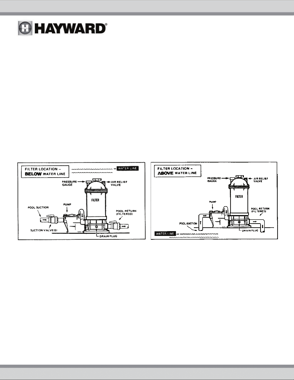
2. Refer to the diagrams on previous page for basic suggested valve installation. Ball valves are recommended where
needed. While systems vary, the main consideration is to provide the desired control of water flow from the pool to the
pump and filter, and back to the pool. When the filter is located below water level, provide valves to prevent back flow of
water to the filter during cleaning and routine servicing.
3. All plumbing on the StarClear filter is 1-1/2" female NPT. When making threaded connections to the filter use plastic
adapters. Apply three turns of TFE tape (or use special plastic pipe sealant) to male threads.
Screw the fitting into the thread hand tight; then using a wrench, tighten one more full turn. Additional tightening is
unnecessary and could result in broken or damaged fittings.
4. Connect the pool suction plumbing between the skimmer, pool outlet, etc. and the pump.
5. Install the pool return plumbing.
6. If the pressure gauge is not installed, apply three wraps of TFE tape to the gauge threads, and
into the threaded hole in the filter head.
7. A filter drain plug is furnished with each filter and is all that is needed for complete filter draining. A manual air relief valve
is furnished to aid in bleeding off unwanted air when starting the filter. The auto air relief provides air removal during
operation.
8. All electrical connections should be made in accordance with local codes.
9. Check for joint leaks before operating
10. Refer to pump instruction booklet for pump information.
carefully
screw the gauge
USE ONLY HAYWARD GENUINE REPLACEMENT PARTS 4
Page 5

STARTING THE FILTER
Be sure filter drain plug is closed. Open manual air relief valve a few turns and open the suction and return valves (when
used).
WARNING COMPONENT SEPARATION HAZARD: Failure to could cause severe personal injury
and/or property damage. OPEN all suction and discharge valves before starting the system.
Be sure locking knob is secure (hand tighten-only slight pressure is required).
Stand clear of the filter and prime and start the pump, following the manufacturer's instructions. Air trapped in the system
will automatically vent to the pool and out air relief valve. Close air relief valve as soon as air is vented.
FILTERING
Filtration starts as soon as flow is steady through the filter. As the filter cartridge removes dirt from the pool water, the
accumulated dirt causes a resistance to flow. As a result, the gauge pressure will rise and the flow will decrease. When the
pressure rises 7-10 psi (.49-.70 Bar) above the starting pressure, or when flow decreases below desired rate, clean or replace
the filter cartridge.
CLEAN / REPLACE CARTRIDGE
REMOVING CARTRIDGE ELEMENT
1. Shut off the pump.
2. If filter is located below water level, close valves or block off suction & discharge lines to prevent backflow of water from
the pool.
3. Remove drain plug and allow water to drain from filter. Close drain plug. (To assist draining process; open air vent a few
turns.)
4. Unscrew and remove locking knob (counterclockwise direction) and carefully lift off top cover to gain access to filter
cartridge.
5. Lift out cartridge and clean. Or, replace with clean, spare cartridge. (See Cleaning Cartridge.)
REINSTALLING CARTRIDGE ELEMENT
1. Clean any collected debris from the bottom of filter body.
2. Carefully replace cartridge element over tie rod and into filter body ensuring that the cartridge sits evenly on the collector
hub in bottom of filter body.
3. Place cover on filter body (being sure filter head 0-ring is in place and clean). Fit tie rod end through center hole.
4. Tighten locking knob in clockwise direction. (Hand tight only.)
5. Proceed as in
STARTING THE FILTER.
CLEANING CARTRIDGE
The cartridge filter element can be cleaned by pressure washing inside and out with a garden hose. (The cartridge is easier
to clean when dry.) After hosing the cartridge, for best results, allow cartridge to dry and carefully brush pleated surface
areas to remove fine particles.
Algae, suntan oil and body oils can form a coating on the cartridge pleats which may not be thoroughly removed by hosing. To
remove such materials, soak the cartridge in a solution of filter element cleaner (various brands available at pool dealer).
Follow manufacturer's directions for use and allow an hour for soaking. Hose thoroughly before reinstalling in filter.
A spare cartridge filter element is an excellent investment. It provides convenience and ensures that your filter will always
be ready to operate at peak efficiency.
Do not pressure wash, as it can damage the filter element.
WINTERIZING (Filter)
In areas where sub-freezing temperatures can be expected, the filter should be drained and/or removed from its, operating
location and stored indoors. Remove and clean cartridge. Reinstall cartridge in filter tank. Tighten locking knob only a few
turns when storing.
SERVICE AND REPAIRS
Consult your local authorized Hayward dealer or service center. No returns may be made directly to the factory without the
expressed written authorization of Hayward Pool Products.
USE ONLY HAYWARD GENUINE REPLACEMENT PARTS 5
Page 6
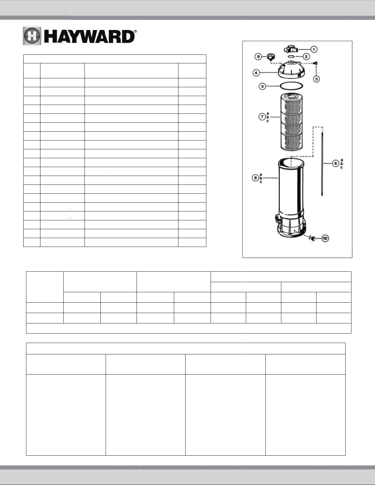
f
o
a
b
a
b
MC2C5
E
O
Z
2
2
R
R
R
B
A
A
A
1
i
n
e
r
F
r
r
r
r
r
r
r
s
T
N
O
R
I
w
e
t
C
n
C
n
C
w
M
A
s
r
f
k
r
f
b
F
g
A
L
E
L
s
d
g
e
A
N
S
N
c
u
e
g
u
C
a
p
R
O
O
U
n
t
s
r
d
Re
N
1
2
3
4
5
6
CX250Z
6
CX500Z
6c
CX750Z
7a
CX250
7b
CX500
7c
CX750
8
CX250
8
CX500
8c
CX750
9
10
CX250Z
PART N
CX250
CX250
ECX132
CX250
CX250
CX250RE
CX500RE
CX750RE
ECX270
REPLAC
.
Lock
7 O-Ri
A Air R
C Filte
Filte
2S Tie R
2S Tie R
S Tie R
E Cart
VS Valu
E Cart
BVS Valu
E Cart
VS Valu
A1 Filte
A1 Filte
A1 Filte
91 Pres
4A 1/2"
EMENT PA
DESCRIPT
ng Knob
g
lief Valve
Head (Dom
Seal Gaske
od C250
od C500
od C750
idge Elemen
e Element (
idge Eleme
e Element (
idge Eleme
e Element (
Body w/Tie
Body w/Tie
Body w/Tie
ure Gauge
Drain Plug
TS
ON
/ O-ring
)
t (C250)
250)
t (C500)
500)
t (C7510)
750)
Rod (C250)
Rod (C500)
Rod (C750)
ith O-Ring
NO.
REQ’D.
1
1
2
1
1
1
1
1
1
1
1
1
1
1
1
1
R
ODEL
50
00
MEDY
EFFEC
FILTRATIO
FT²
25
50
IVE
AREA
M²
2.3
4.7
MAXIMU
1. Check
2. Check
3. Check
4. Clean
(see Pa
LOW W
pump s
for deb
in inta
discha
intake l
by bub
pool).
DESIGN F
RESID
GPM
25
50
WORKING
PROB
TER FLOW
kimmer and
trainer baske
is.
or restriction
e and
ge lines.
or air leak in
ine (indicate
les returnin
ilter Cartridg
e 5)
OW RATE
NTIAL
LPM
95
190
PRESSURE I
EM SOLVI
SHOR
1. Che
ts
to
s
and
2. Be s
lev
ran
req
IN
18
18
50 PSI (3.4
G
T FILTER CY
k for algae in
treat as requ
ure chlorine
ls are in pro
e (adjust as
ired).
REQUIRED
SI
DE
5 BAR)
LES P
pool
ired.
nd pH
er
CM
46
46
CLEARANCE
IN
18
28
OL WATER
CLEAR
1.
Check chlori
total alkalini
and adjust a
2.
Be sure flow
through filter
sufficient.
3.
Operate filte
longer perio
AB
WON’T
P
e, pH and
y levels
required.
rate
is
for
s.
VE
CM
46
71
USE
NLY HAYW
RD GENUI
E REPLAC
EMENT PA
TS
6
Page 7
0
To original purchasers of this equipment, Hayward Pool Products, Inc. warrants its products to be free from defects in materials and workmanship for a
period of ONE (1) year from the date of purchase, when used in single family residential applications.
The limited warranty excludes damage from freezing, negligence, improper installation, improper use or care or any Acts of God. Parts that fail or
become defective during the warranty period shall be repaired or replaced, at our option, within 90 days of the receipt of defective product, barring
unforeseen delays, without charge.
Proof of purchase is required for warranty service. In the event proof of purchase is not available, the manufacturing date of the product will be the
sole determination of the purchase date.
To obtain warranty service, please contact the place of purchase or the nearest Hayward Authorized Service Center. For assistance on your nearest
Hayward Authorized Service Center please visit us at
Hayward shall not be responsible for cartage, removal, repair or installation labor or any other such costs incurred in obtaining warranty replacements
or repair.
The Hayward Pool products warranty does not apply to components manufactured by others. For such products, the warranty established by the
respective manufacturer will apply.
The express limited warranty above constitutes the entire warranty of Hayward Pool Products with respect to its’ pool products and is in lieu of all other
warranties expressed or implied, including warranties of merchantability or fitness for a particular purpose. In no event shall Hayward Pool products be
responsible for any consequential, special or incidental damages of any nature.
Some states do not allow a limitation on how long an implied warranty lasts, or the exclusion of incidental or consequential damages, so the above
limitation may not apply to you. This warranty gives you specific legal rights, and you may also have other rights, which vary from state to state.
*Supersedes all previous publications. Elizabeth, NJ 07207
HAYWARD® Pool Products Limited Warranty
www.hayward.com.
Hayward Pool Products
620 Division Street
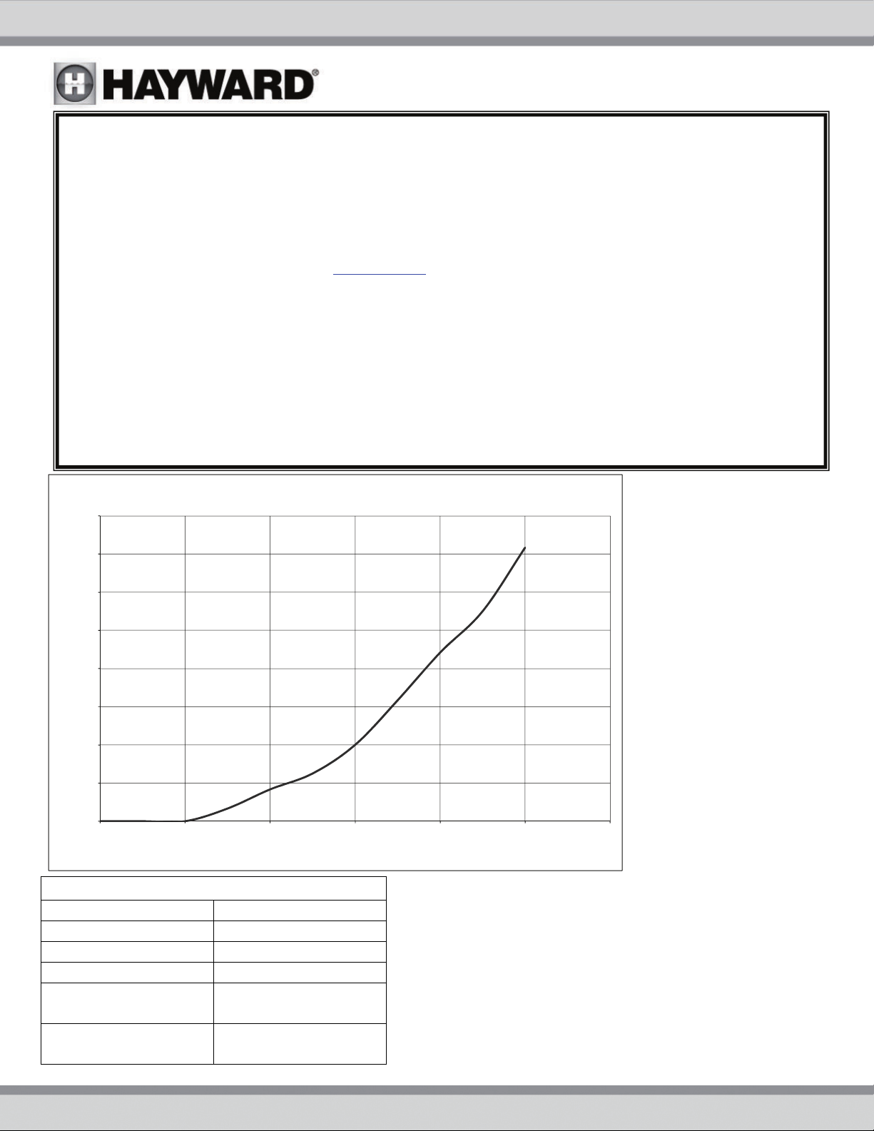
HEAD LOSS CURVE
1.6
1.4
1.2
1.0
0.8
2.31 Feet of Water = 1 PSI
0.6
Head Loss (Feet of Water)
0.4
0.2
0.0
0 10203040506
SUGGESTED POOL CHEMISTRY LEVELS
pH 7.2 to 7.8
TOTAL ALKALINITY 80 to 120 ppm
CALCIUM HARDNESS 200 to 400 ppm
COMBINED CHLORINE .2 ppm Maximum
CHLORINE
(STABILIZED)
CHLORINE STABILIZER
(Cyanuric Acid)
1.0 to 3.0 ppm
60 to 80 ppm
Flow (gpm)
C250
C500
USE ONLY HAYWARD GENUINE REPLACEMENT PARTS 7
Page 8
-
t
a
t
e
y
i
d
o
e
e
a
n
R
F
g
r
d
-
™
r
t
_
_
_
_
_
_
_
n
p
t
o
d
e
T
a
n
b
-
_
_
_
_
_
_
_
_
_
n
s
m
t
O
_
d
-
T
R
a
_
a
_
_
s
e
o
o
f
a
o
W
A
T
_
r
n
m
n
_
_
_
e
_
_
e
d
p
p
a
R
A
N
A
d
e
a
a
_
_
_
_
_
_
_
g
o
2
e
/
-
a
Year
1
c
u
m
_
e Co
a
n
_
R
r
-
C
_
_
_
_
_
_
b
.
-
_
_
_
_
_
_
_
b
_
p
n
_
g
_
_
_
_
_
PRODUC
(Retain
REGISTR
For Your Recor
TION
s)
▲
---
---------------
S
arClear
DATE O
DETACH
INSTALLA
Retain this W
HERE: Fill out
---------------
CARTRI
ION __
rranty Certific
ottom portion c
---------------
DGE FIL
________
ate (upper po
ompletely and
---------------
ER
egister onli
________
tion) in a saf
ail within 10 d
----------------
e at www.h
and conveni
ys of purchase
---------------
W
ward.com
nt location fo
installation or
---------------
rranty
r your records
egister online.
---------------
ard Reg
--------------
istratio
Ple
se Print Clea
Firs
Name____
Str
et Address_
Cit
__________
Pho
ne Number_
E-M
ail Address_
Ser
al Number
el Number_
Mo
Poo
l Capacity__
If y
ur product co
nec
ssary to com
Inst
ad, complete
seri
l number tha
Ple
ase include me
l to: Haywar
Mai
Att
: Warranty D
Or
EGISTER YOU
Hayward is a re
© 2015 Haywa
ly:
__________
_________
__________
_________
_________
___________
__________
tains compo
lete warranty
warranty regi
is located on
n all e-mail com
Pool Produc
pt
R WARRANTY
istered trademark a
Industries, Inc.
____ Last N
__________
_______ St
_________ P
__________
__________
(U.S. Gallon
ents that hav
registration f
tration only f
the outside o
unications reg
s, 620 Divisi
ON-LINE AT
d StarClear is a tra
me_______
__________
te________
urchase Dat
__________
__________
)
individual s
r those indivi
r the overall
the product
rding Hayward
n Street, Eliz
WW.HAYWA
emark of Hayward I
__________
_________
__ Zip_____
__________
_________
__________
rial numbers,
ual compone
roduct, usin
ackaging.
Equipment or pr
beth, NJ 07
D.COM
dustries, Inc.
_______
______
______
______
______
______
it is not
nts.
the
motions.
07
s Pool has been
<
year 1-3
Pur
hased from____
B
ilder Retailer
Co
pany Name____
Add
ress__________
_____________
City
Pho
ne___________
Typ
of Pool:
ncrete/Gunite
ther__________
O
N
ew Installation
Inst
llation for:
I
Ground A
in service
4-5 6-10
_____________
Pool Service
_____________
_____________
_____ State___
_____________
Vinyl Fi
_____________
Re
ove Ground
11-15 >15
__________
Internet/Catalo
_____________
_____________
_ Zip_________
_____________
erglass
____
lacement
Spa
USE
NLY HAYW
RD GENUI
E REPLAC
EMENT PA
TS
8
 Loading...