

Hayward BYCS Installation, Operation And Maintenance Instructions

HAYWARD FLOW CONTROL PRODUCTS
Size
Nominal
Minimum
Pipe/Flange
Bore (in)
Stud Dia (in)
x
Length (in)
Bolt Dia (in)
Thread
Flat Face Type
Flange Torque
Ft Lb
Van-Stone Type
Flange Torque
Ft Lb
2”
1.880
5/8 x 4.5
5/8-11 UNC
15-25
10-20
2-1/2”
2.250
5/8 x 5.5
5/8-11 UNC
15-25
10-20
3”
2.830
5/8 x 5.5
5/8-11 UNC
20-25
10-20
4”
3.750
5/8 x 6.0
5/8-11 UNC
20-25
10-20
5”
4.720
3/4 x 6.5
3/4-10 UNC
20-25
10-20
6”
5.680
3/4 x 6.5
3/4-10 UNC
30-40
10-20
8”
7.540
3/4 x 7.0
3/4-10 UNC
30-40
20-30
BYCS SERIES BUTTERFLY VALVE
INSTALLATION, OPERATION AND MAINTENANCE INSTRUCTIONS
PLEASE READ THE FOLLOWING INFORMATION PRIOR TO INSTALLING AND USING
HAYWARD VALVES, STRAINERS, FILTERS, AND OTHER ASSOCIATED PRODUCTS. FAILURE
TO FOLLOW THESE INSTRUCTIONS MAY RESULT IN SERIOUS INJURY.
1. Hayward guarantees its products against defective material and workmanship only. Hayward assumes no responsibility for damage or injuries resulting from
improper installation, misapplication, or abuse of any product.
2. Hayward assumes no responsibility for damage or injury resulting from chemical incompatibility between its products and the process fluids to which they are
subjected. Compatibility charts provided in Hayward literature are based on ambient temperatures of 70°F and are for reference only. Customer should always
test to determine application suitability.
3. Consult Hayward literature to determine operating pressure and temperature limitations before installing any Hayward product. Note that the maximum
recommended fluid velocity through any Hayward product is eight feet per second (8 ft/s). Higher flow rates can result in possible damage due to the water
hammer effect. Also note that maximum operating pressure is dependent upon material selection as well as operating temperature.
4. Hayward products are designed primarily for use with non-compressible liquids. They should NEVER be used or tested with compressible fluids such as
compressed air or nitrogen.
5. Systems should always be depressurized and drained prior to installing or maintaining Hayward products.
6. Temperature effect on piping systems should always be considered when the systems are initially designed. Piping systems must be designed and supported to
prevent excess mechanical loading on Hayward equipment due to system misalignment, weight, shock, vibration, and the effects of thermal expansion and
contraction.
7. Because PVC and CPVC plastic products become brittle below 40°F, Hayward recommends caution in their installation and use below this temperature.
8. Published operating torque requirements are based upon testing of new valves using clean water at 70°F. Valve torque is affected by many factors including fluid
chemistry, viscosity, flow rate, and temperature. These should be considered when sizing electric or pneumatic actuators.
9. Due to differential thermal expansion rates between metal and plastic, transmittal of pipe vibration, and pipe loading forces DIRECT INSTALLATION OF
PLASTIC VALVES INTO METAL PIPING SYSTEMS IS NOT RECOMMENDED. Wherever installation of plastic valves into metal piping systems is
necessary, it is recommended that at least 10 pipe diameters in length of plastic pipe be installed upstream and downstream of the plastic valve to compensate for
the factors mentioned above.
INSTALLATION
Hayward Series BYCS Butterfly Valves should be installed between two pipe flanges. In dead end service, it is recommended they be installed
between one pipe flange and a downstream companion flange, flange ring, or blind flange. The use of additional gaskets is not necessary and is
not recommended.
When installed between two existing flanges, the flanges should be separated to provide clearance on the face to face of the valve. This will
prevent the valve sealing surfaces from distortion and from being damaged during installation. Pipe flanges should be clean and free of debris
including old gasket material. A light coating of a lubricant such as “Non-Fluid Oil” #666 applied to the flange sealing surface will aid in installation.
Hayward Series BYCS Butterfly Valves are designed for use with all pipe flanges that have bores equal to or larger than Schedule 80 pipe as listed
below. The inside of the pipe flange must be chamfered at a 45-degree angle to a diameter listed if the inside bore is smaller than listed. Sharp
edges and burrs must be removed.
Manual Series BYCS Butterfly Valves are shipped without the lever handle installed. The lever handle should be assembled to valve before
installing the valve in line. The lever handle is installed by pulling the lever grip, carefully engaging the stem with the mating square socket in the
handle while aligning the point of the lever with the disc, pushing down gently on the handle until it is fully engaged on the stem and releasing the
lever grip. Once the lever handle is properly positioned, install the flat washer and the Phillips-head screw; the screw should engage the tapped
hole in the top of the stem. Push the red bezel with the molded-in “H” into the socket on top of the lever handle.
Valves should be opened approximately 15º during installation. To prevent damage to the edge of the disc by the mating flanges, do not turn the
disc to the fully open position during installation.
Install the valves using well-lubricated studs, or bolts, and nuts. For plastic flanges, metal washers are recommended between nut/bolt head and
pipe flange. With a torque wrench, uniformly tighten nut to approximately 10 foot pounds in an alternating sequence, diametrically opposed to the
previously tightened nut. Final tightening should be performed in the same sequence following the recommended torque in the following chart.
For plastic Schedule 80 pipe, the maximum allowable displacement is 1/8” off center in any direction. Maximum angular misalignment is 1/16”.
Normal pipe hanger spacing is recommended. Do not allow valve to support the weight of pipe. When using pneumatic or electric actuators,
additional support directly to the actuator is recommended.
RECOMMENDED FLANGE BOLT TORQUE FOR BUTTERFLY VALVES
NOTE: “LUG” design not available on Series BYCS.
OPERATION
BYCSIS Rev. B
2/15/12
ECR 537U
When installation is complete, check for proper alignment.
Fully open and close the valve 3 or 4 times. With the lever handle installed, fully squeeze the lever grip and hold in for the full stroke 90º stroke of
the lever handle. For optimum operation, the lever handle should be held up until full stroke of valve is reached.
The lever grip should only be released at end of stroke, or at an intermediate disc position, if desired.
Check to make sure that the end of the lever grip nearest the valve body is fully engaged in one of the retention notches on the stop plate. If using
the valve for throttling applications, it is important that the lever grip is engaged in the notches of the stop plate to ensure that the disc will maintain
its desired setting.
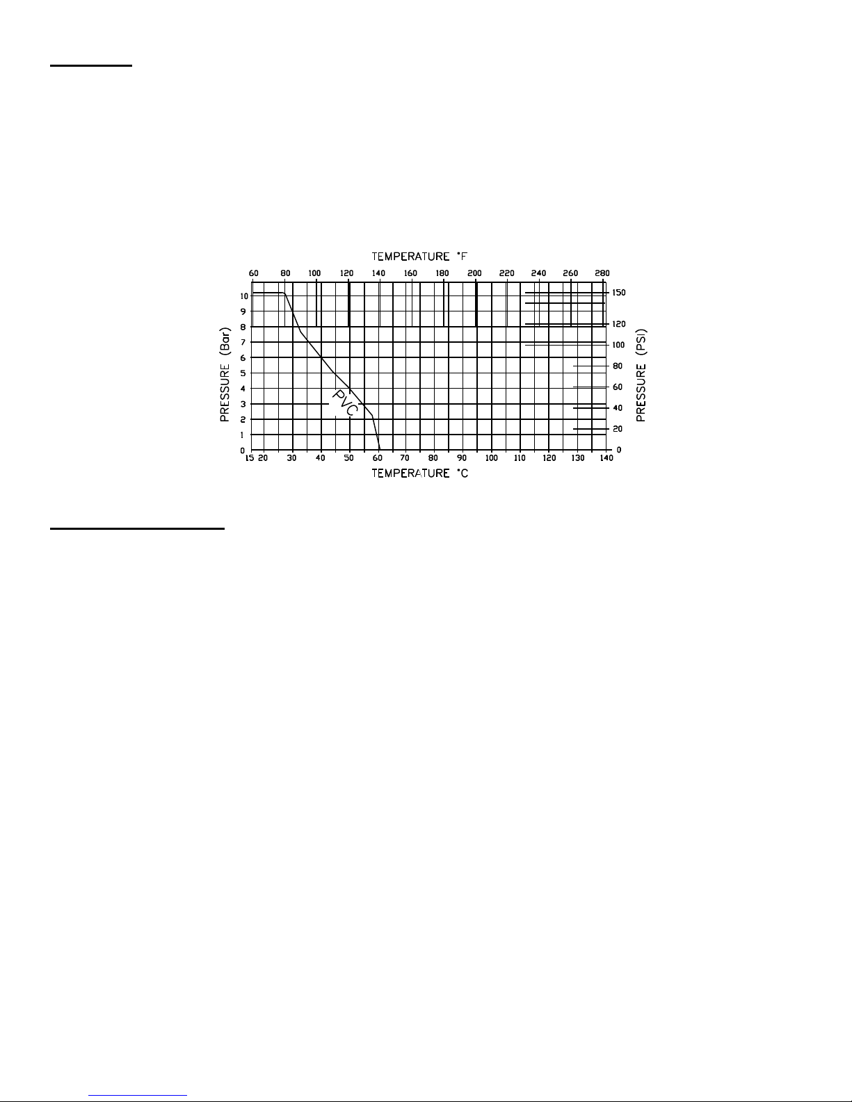
Maximum operating pressure is 150 PSI at 70°F. Maximum operating temperature is 140°F
The pressure rating of Hayward Series BYCS Butterfly Valves must be derated as temperature is elevated. See Chart Below to determine the pressure
rating at elevated temperatures.
MAINTENANCE OF VALVE
I. Minimal valve maintenance is required.
II. Actuator Assembly: Actuators can be removed and installed without removing valve from the line. The line should be depressurized before any
actuator is removed.
A. Lever Handle Assembly: remove red logo bezel by lifting with a thin bladed screwdriver or knife. Remove exposed Phillips-head screw and
flat washer. Lift the handle off.
B. Gear Operators (if supplied): remove four (4) hex nuts and the washers that hold the actuator to the body.
C. Pneumatic/Electric Actuators (if supplied): remove by unscrewing either four (4) socket head cap screws or hex nuts which hold the actuator
to the valve.
 Loading...