

Hayward Aqua Plus, Aqua Plus Controls plus Chlorination, Aqua Plus PL-PLUS, Aqua Plus PL-PLUS-20 Operation Manual
Page 1
Quarterly Monthly Weekly
Free Chlorine 1.0 - 3.0 ppm
pH 7.2 - 7.8
Raise desired output % to
increase, lower desired output %
to decrease -OR- increase or
decrease pump filtration time.
Too low - add soda ash.
Too high - add muriatic acid
Alkalinity 80 - 120 ppm
Salt 2700 - 3400 ppm Add salt as required to increase.
Add baking soda to increase.
Stabilizer 60 - 80 ppm Add cyanuric acid to increase.
Calcium 200 - 400 ppm Add calcium to increase.
Electrolytic Cell inspect & clean Refer to section in manual.
TEST IDEAL RANGE ADJUSTMENT REQUIRED
Drain and add water to decrease.
Add acid as required to decrease.
Automation and Chlorination
Operation Manual
for models
PL-PLUS
PL-PLUS-20
Aqua Plus
®
092360D RevF
Copyright © 2010 Hayward
www.haywardnet.com
620 Division St.
Elizabeth, NJ 07207
Page 2

IMPORTANT SAFETY INSTRUCTIONS
When using this electrical equipment, basic safety precautions should always
be followed, including the following:
•
READ AND FOLLOW ALL INSTRUCTIONS
•
!
WARNING: Disconnect all AC power during installation.
•
!
WARNING: Water in excess of 100 degrees Fahrenheit may be
hazardous to your health.
•
!
WARNING: To reduce the risk of injury, do not permit children to
use this product unless they are closely supervised at all times.
• A green colored terminal marked “Grounding” is located inside the wiring
compartment. To reduce the risk of electric shock, this terminal must be
connected to the grounding means provided in the electric supply service
panel with a continuous copper wire equivalent in size to the circuit
conductors supplying the equipment.
• One bonding lug for US models (two for Canadian models) is provided on the
external surface. To reduce the risk of electric shock, connect the local
common bonding grid in the area of the swimming pool, spa, or hot tub to
these terminals with an insulated or bare copper conductor not smaller than 8
AWG US / 6 AWG Canada.
• All field installed metal components such as rails, ladders, drains, or other
similar hardware within 3 meters of the pool, spa or hot tub shall be bonded
to the equipment grounding bus with copper conductors not smaller than
8 AWG US / 6 AWG Canada.
• SAVE THESE INSTRUCTIONS
36
LIMITED WARRANTY (effective 04/01/09) Hayward/Goldline warrants its Pro Logic and E-Command
pool automation products as well as its Aqua Rite, Aqua Rite Pro, Aqua Plus and SwimPure chlorination products
to be free of defects in materials and workmanship, under normal use and service, for a period of three (3) years.
Hayward/Goldline also warrants its Aqua Trol chlorination products to be free of defects in materials and workmanship, under normal use and service for a period of one (1) year. These warranties are applicable from the initial
date of installation on private residential swimming pools in the US and Canada.
Hayward/Goldline warrants all the above-identified pool automation and chlorination products installed on commercial swimming pools and on swimming pools outside of the US and Canada for a period of one (1) year.
Likewise, Hayward/Goldline warrants all accessories and replacement parts for the above-identified pool automation and chlorination products for a period of one (1) year. Each of these warranties is not transferable and
applies only to the original owner.
Proof of purchase is required for warranty service. If written proof of purchase is not provided, the manufacturing
date code will be the sole determinant of the date of installation of the product. To obtain warranty service or
repair, please contact the place of purchase or the nearest Hayward/Goldline authorized warranty service center.
For more information on authorized service centers please contact the Hayward/Goldline Technical Service Support Center (61 Whitecap Road, North Kingstown RI, 02852) or visit the Goldline web site at
www.goldlinecontrols.com or the Hayward website at www.haywardnet.com.
WARRANTY EXCLUSIONS:
1. Material supplied or workmanship performed by others in process of installation.
2. Damage resulting from improper installation including installation on pools larger than the product rating.
3. Problems resulting from failure to install, operate or maintain the product(s) in accordance with the recommendations contained in the owners manual(s).
4. Problems resulting from failure to maintain pool water chemistry in accordance with the recommendations in the
owners manual(s).
5. Problems resulting from tampering, accident, abuse, negligence, unauthorized repairs or alternations, fire, flood,
lightning, freezing, external water, degradation of natural stone used in or immediately adjacent to a pool or spa,
war or acts of God.
DISCLAIMER. THE EXPRESS LIMITED WARRANTIES ABOVE CONSTITUTE THE ENTIRE
WARRANTIES WITH RESPECT TO THE ABOVE-IDENTIFIED HAYWARD/GOLDLINE POOL
AUTOMATION AND CHLORINATION PRODUCTS AND IS IN LIEU OF ALL OTHER WARRANTIES, EXPRESS OR IMPLIED, INCLUDING WARRANTIES OF MERCHANTABILITY OR FITNESS FOR A PARTICULAR PURPOSE. THESE WARRANTIES GIVE YOU SPECIFIC LEGAL
RIGHTS, AND YOU MAY ALSO HAVE OTHER RIGHTS OF EQUIPMENT, LOST PROFITS OR
REVENUE, COSTS OF RENTING REPLACEMENTS, AND OTHER ADDITIONAL EXPENSES,
EVEN IF THE SELLER HAD BEEN ADVISED OF THE POSSIBILITY OF SUCH DAMAGES. SOME
STATES DO NOT ALLOW THE EXCLUSION OF LIMITATION OF INCIDENTAL OR CONSEQUENTIAL DAMAGES, SO THE ABOVE LIMITATION OR EXCLUSION MAY NOT APPLY TO
YOU.
NO WHOLESALER, AGENT, DEALER, CONTRACTOR OR OTHER PERSON IS AUTHORIZED
TO PROVIDE, SUPPLEMENT OR MODIFY ANY WARRANTY ON BEHALF OF HAYWARD/GOLDLINE.
THESE WARRANTIES ARE VOID IF THE PRODUCT HAS BEEN ALTERED IN ANY WAY AFTER
LEAVING THE FACTORY. FOR THE ABOVE-IDENTIFIED CHLORINATION PRODUCTS, THESE
WARRANTIES ALSO ARE VOID IF, DURING THE WARRANTY PERIOD, YOU USE A REPLACEMENT CHLORINATOR CELL OTHER THAN AN UNMODIFIED, NEW HAYWARD/GOLDLINE
CHLORINATOR CELL PURCHASED FROM HAYWARD/GOLDLINE. IF A WARRANTY BECOMES VOID, YOU STILL MAY PURCHASE SERVICE AND/OR TELEPHONE TECHNICAL
SUPPORT AT THE THEN CURRENT TIME AND MATERIAL RATES.
Page 3

Table of Contents
System Overview Block Diagram....................................................................... 1
Automation............................................................................. 1
Chlorination............................................................................ 1
Default Display....................................................................... 2
Manual System Filter Pump............................................................................. 3
Operation Lights and Aux Outputs.......................................................... 4
Pool/Spa Valves..................................................................... 4
Service.................................................................................... 4
Automatic System Using the Programming Buttons.......................................... 5
Operation Programming Menu Flow Chart........................................... 6
(Programming) Settings Menu........................................................................ 7
Timers Menu.......................................................................... 10
Configuration Menu............................................................... 13
Maintenance Menu............................................................... 2 3
Quick “How To” Operate the Spa - Manually.................................................. 24
Guide Operate the Spa - Automatically.......................................... 24
Set the Heater Temperature................................................. 24
Set the Chlorinator Output ................................................... 24
Start/Stop Superchlorination................................................ 25
Program a Timeclock............................................................ 25
Program a Countdown Timer............................................... 25
Enter/Exit Service Mode....................................................... 25
Chlorinator Operation/ Saturation Index..................................................................... 26
Water Chemistry Salt Level................................................................................ 27
Type of Salt............................................................................ 27
How to Add or Remove Salt................................................. 27
System Maintenance Servicing and Cleaning the Turbo Cell................................ 30
Winterizing.............................................................................. 30
Spring Startup........................................................................ 30
Troubleshooting & Service Mode ....................................................................... 31
Diagnostic Information Check System Indicator........................................................ 31
Diagnostic Menu................................................................... 33
Warranty Aqua Plus Warranty................................................................ 36
35
Main Software
Revision 4.00
Display Software
remote-08 r3.10
RF Base Software
r1.20 ID:1234
Filter VSC
Software r1.00
Pool Filter Bridge
Software r1.00
6B Spa Software
Remote A r1.00
Filter Drive
Software r1.00
Filter Display
Software r1.00
No function
No function
No function
No function
No function
No function
No function
No function
Move to previous/next menu item
Move to previous/next menu item
Move to previous/next menu item
Move to previous/next menu item
Move to previous/next menu item
Move to previous/next menu item
Move to previous/next menu item
Move to previous/next menu item
Chemistry Sense
Software r1.00
VSP Software
± to view
No function
Push to view the software revi sion of the connected VSPs
Move to previous/next menu item
Move to previous/next menu item
if TriStar VSPs are detected
if TriStar VSPs are detected
if EcoStar VSPs are detected
if EcoStar VSPs are detected
Available displays depend on configuration. If you call the Hayward Technical Service Dept. for
assistance, they may ask for the software revisions of both the main unit and each of the display/
keypads or other devices that are attached to the system. Note that it is possible that different
display/keypads have different software revision levels. For this reason, it is advisable to check this
diagnostic menu item on every display.
Page 4

1
System Overview
The Hayward Aqua Plus is a multifunction pool controller used to fully manage your pool/spa system. The Aqua
Plus can control pumps, valves, lighting, heaters, and chlorination. Although the Aqua Plus is easy to use, it is
important to completely read through this operating manual before attempting to operate the control.
NOTE: This manual assumes that the Aqua Plus has been wired and configured according to the Installation
Manual. Aspects of the Aqua Plus that pertain to system setup are not covered in this manual.
Automation
The Aqua Plus can control up to 4 high voltage (120/240V) pieces of equipment, up to 3 automatic valve actuators, and a conventional and solar heater. Both manual and automatic (programmed) operation are available. All
of the control functions can be programmed at a display/keypad which is part of the main unit (typically located
near the pool equipment) or at one or more remote display/keypads.
Chlorination
With the use of the included Turbo Cell and flow switch, the Aqua Plus is also an automatic chlorine generation
system for pool and/or spa sanitization. When enabled (see Configuration Menu), this operation requires a low
concentration of salt (sodium chloride) in the pool/spa water. The Aqua Plus automatically converts the salt into
free chlorine which kills bacteria and algae in the pool/spa. Chlorine will revert back to sodium chloride after killing
bacteria. These reactions will continuously recycle, virtually eliminating the need to add sanitizing chemicals to your
pool/spa. The only time you may need to add more salt to the pool/spa is when water is replenished due to
backwashing, draining, or splashing (not evaporation).
34
Water
Air
Solar
Optional
Flow Switch
External Input
240 VAC
Power
Filter Pump
Lights
Aux 1
Aux 2
Pool/Spa Suction &
Return Valves
Valv e 3
Heater
Optional
Chlorinator Cell
Circuit Breaker
Subpanel
Main Display
Keypad
Optional
Remote Displa y
Keypad
(maximum of three)
Optional
Wireless Base
Receiver
Tem pe r at u re
Sensors
120/240V
Relays
24V Valve
A
ctuators
Optional Wireless
Remote Display
Keypad
Optional Wireless
Spaside Re mote
LDLINE
CONTROLS INC.
G
POOL SPA
ON OFF
ON OFF
ON OFF
ON OFF
ON OFF
VALVES
FILTER
HEATER
LIGHTS
AUX1
AUX2
AQL-CHEM Sensing Kit). The Aqua Plus will refer to these levels to determine how much chlorine to
generate (ORP) and, if using an AQL-CHEM2 dispense kit, how much CO
2
or acid to dispense (pH).
Refer to the AQL-CHEM manual for specific information about these levels as well as the recommended
ranges.
Flow Switch
Flow
No function
Move to previous/nex t menu item
This display will be shown only if the chlorinator is enabled. The current status of the flow switch is
displayed. There is a short delay when transitioning from flow to no-flow and a longer delay on the
transition from no-flow to flow. The delay time is displayed.
Air Sensor
94ºF
Cell Temp Sensor
77ºF
Solar Sensor
Short circuit
Water Sensor
Open circui t
No function
No function
No function
No function
Move to previous/next menu item
Move to previous/next menu item
Move to previous/next menu item
Move to previous/next menu item
If the sensor appears to operating properly, then the temperature will be displayed. If this temperature
is not correct then check the placement of the sensor. If the problem is not placement related, then the
sensor will, most likely, require replacement. If the display is “Open Circuit” or “Short Circuit” then
check the wiring to the sensor and also make sure that the wires are secure in the terminal block in the
Aqua Plus main unit.
VSP Speed/Power
Filter
± to view
Push to view the act ual speed and power rep orted by the VSP
No function
Move to previou s/next menu item
Move to previous/ne xt menu item
if EcoStar VSPs are detected
Page 5
2
The Aqua Plus is designed to handle the purification needs of most residential swimming pools up to 40,000 gallons
(150,000 liters), or the needs of most commercial pools up to 25,000 gallons (95,000 liters). Check local codes
for other restrictions. The actual amount of chlorination required to properly sanitize a pool varies due to bather
load, rainfall, temperature, and the pool’s cleanliness.
For pools larger than 40,000 gallons, the Aqua Plus can control one or more Hayward Aqua Rite chlorinators to
supplement chlorine production.
NOTE: Before installing this product as part of a saline water purification system in a pool or spa using natural
stone for coping or for immediately adjacent patios/decking, a qualified stone installation specialist should be
consulted regarding the appropriate type, installation, sealant (if any) and maintenance of stone used around a
saline pool with electronic chlorine generator in your particular location and circumstances.
NOTE: The use of dry acid (sodium bisulfate) to adjust pool pH is discouraged especially in arid regions where
pool water is subject to excessive evaporation and is not commonly diluted with fresh water. Dry acid can cause a
buildup of by-products that can damage your chlorinator cell.
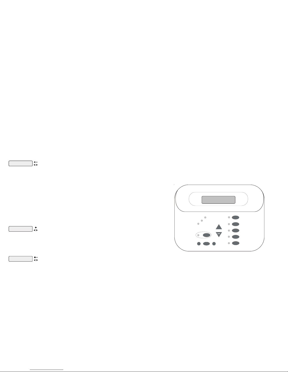
Default Display
Turn power on at the main panel and turn the Aqua Plus control power circuit breaker on. The keypad will show
the default display. The default display alternates between the day/time, air and pool (or spa) temperature, pool/
spa sanitizer setting, and salt level. Under certain circumstances, additional displays may be added to the default
menu to inform you about system operation. Refer to the Programming Menu Flowchart on page 6 to view all
possible displays. The Aqua Plus will automatically scroll through all of the available default menu displays or you
can press “<” or “>” to manually scroll.
33
• ORP High - Check Chlor -- If an ORP level of 950mV or higher is detected. Check the chlorinator for proper
operation.
• ORP High - Chlor Off -- If an ORP level of 950mV or higher is detected and the chlorine feed mode is ORP
Auto Sensing, the chlorinator has been turned off. Check the chlorinator for proper operation.
• ORP Timeout -Chlor Off -- If the unit has been chlorinating for more than the selected sanitizer timeout
without reaching the desired level, the chlorinator has been turned off. Press the “+” button to reset the alarm
and resume chlorination.
• Ambient Sensor -- If the Aqua Plus internal temperature sensor is either an open or short circuit.
For helpful troubleshooting information on any of these issues, go to the Diagnostic Menu and then scroll through
the various items until you see the cause for the “CHECK SYSTEM” LED being illuminated.
Diagnostic Menu
To enter the Diagnostic Menu, press the “Menu” button repeatedly until the display shows “Diagnostic Menu”. At
this point, you can use either the “<” or “>” buttons to scroll through the various menu items which are described
below:
Set Day and Time
Wednesday 10:37P
Move to previous/next menu item
+23.45 +6.75A
84°F 3200PPM
Press to switch chl orinator operation to opposite po larity (15 second delay)
+/- 23.45V is the voltage applied to the chlorinator cell
+/-6.75A is the current (amps) through the cell
84ºF is the water temperature at the cell
3200PPM is the “instant” salt level at this time
This display will be shown only if the chlorinator is enabled. For the chlorinator to be operating,
several other things must be happening: the filter pump must be running, the flow switch must be
detecting flow, the chlorinator setting must be set greater than 0%, the water temperature at the cell
must be between 50ºF and 140ºF, and the salt level must be within the operating range. If any of these
conditions are not met, the chlorinator diagnostic display will tell you the reason. It’s possible to have
more than one reason, in which case after you rectify what was displayed the first time, a second
display will appear.
If the current (amps) display is 0.00A, then the chlorinator is operating normally but is in the off part
of its normal operating cycle. Simply press either the “+” or “-“ key to start a new cycle.
The Aqua Plus periodically reverses the polarity of the voltage applied to the cell in order to
automatically clean off any calcium deposits. It is important that you check the chlorinator operation
in both polarities. To do this, press either the “+” or “-“ buttons and the chlorinator will turn off, wait
for 15 seconds and then turn on in the opposite polarity.
If a conventional or solar heater is operating, it is likely that the temperature of the water at the cell is
higher than the pool/spa water temperature displayed on the Aqua Plus default display.
Instant Salt
3200 PPM (+=save)
Move to previous/next menu item
Press to load the “ Instant Salt” into the averaged salt display
This display will be shown only if the chlorinator is enabled. This display shows “Instant Salt” or
“Instant Minerals” (if Chlor. Config. is set for “Display Minerals”). The “Instant Salt” is calculated
based on the voltage, current (amps), and water temperature at the cell. This is different than the
“average salt” value which is displayed as part of the default menu. There are a number of reasons
why instant and average salt readings may differ. Some of these include salt having just been added
to the pool and not yet thoroughly mixed, calcium buildup on the cell, and the cell aging.
pH 7.5 (On)
ORP 700 mV (On)
No function
Move to previous/next menu item
if AQL-CHEM is used
This display will be shown only if sensing is enabled. This display shows both pH and ORP levels/
status when chemistry sensing is enabled via the Chemistry Configuration Wizard (requires the use of
Pool/Spa
Filter
Lights
Aux 1
Aux 2
Menu
>
>
Service
+
Saturday
11:45A
Heater
Option Valve
Check System
Page 6

3
Manual System Operation
While the main objective of the Aqua Plus is to automate the operation of your pool/spa system, there may be
certain times when you want to override the automatic operation and control the equipment manually. To operate
the pool equipment manually while keeping the automation active, perform the following procedures. Note that if
you turn a relay on manually, it will remain on until either you turn it off manually, or the next time the programmed
automatic operation would normally turn that relay off. Example: the filter pump is programmed to run from 9:00A
to 5:00P daily. If you turn the filter pump on manually at 8:00PM, it will run continuously until the next day at
5:00PM at which time it will turn off and follow the normal program from then on. Manually turning off a relay
works in a similar fashion.
Filter Pump
Single Speed Filter Pump: If the pump is currently off, press the FILTER button to turn on the pump. Pressing the
FILTER button again will turn off the pump. However, if there is a heater in the system, and it is operating, and the
“Heater Cooldown” feature is enabled (Configuration Menu) then: when you press the FILTER button to turn off
the filter, only the heater will turn off, the Filter LED will flash and the display will indicate “Heater Cooldown”. At
this point the filter pump will automatically turn off after 5 minutes of heater cooldown operation. If you want to
override the heater cooldown, simply press the FILTER button again to turn off the filter pump.
Two Speed Filter Pump: If the pump is currently off, simply press the “FILTER” button to turn on high speed
operation of the filter pump. The “Filter” LED will illuminate continuously. Pressing the “FILTER” button again will
switch to low speed operation and the “FILTER” LED will flash. Note that if the pump has been off for more than
30 seconds, it will run at high(est) speed for 3 minutes regardless of selection. This high speed operation helps allow
the pump to prime and establish normal water flow.
Variable Speed Filter Pump: If the pump is currently off, press the “FILTER” button to turn the filter pump on to
the last speed (1, 2, 3, or 4) that was used. A temporary display is generated indicating the current speed selection
(Filter On:Spd 1). Pushing the “+” or “-” button changes the speed selection. If the pump has been off for more than
30 seconds, it will run at the highest speed for 3 minutes regardless of selection. This high speed operation helps
allow the pump to prime and establish normal water flow.
Freeze Protection: This function protects the pool, plumbing, and equipment against freeze damage. If Freeze
Protection is enabled and the AIR temperature sensor falls below the preset freeze protection temperature (see
Filter Configuration), the Aqua Plus will turn on the filter pump to circulate the water.
External Input Interlock:
If enabled, this function will force the filter pump off when the external input is active. External Input Interlock will
have precedence over Freeze Protection for Filter output.
32
• Low Volts -- If the chlorinator cell voltage is too low.
• No Cell Power -- If no chlorinator cell power is detected on the printed circuit board.
• Check Flow Switch -- If the flow switch input is invalid.
• Cell Power Error -- If a chlorinator cell power error is detected on the printed circuit board.
• Cell Missing -- If the chlorinator is enabled but no cell is detected.
• Filter VSP Comm Error-- If variable speed is selected for the Filter and the Hayward VSP interface
is not responding.
• Filter VSP Drive Comm Error -- If variable speed is selected for the Filter and the Hayward VSP
drive controller is not responding.
• Filter VSP Err: x -- If variable speed is selected for the Filter and the Hayward VSP is indicating and
error. x is the same decimal error displayed by the VSP itself.
• Aux1 VSP Comm Error -- If variable speed is selected for the Aux1 relay type and the Hayward VSP
interface is not responding.
• Aux1 VSP Drive Comm Error -- If variable speed is selected for the Aux1 relay type and the
Hayward VSP drive controller is not responding.
• Aux1 VSP Err: x -- If variable speed is selected for the Aux1 relay type and the Hayward VSP is
indicating and error. x is the same decimal error displayed by the VSP itself.
For Pool Filter and Aux using Gen2 EcoStar Variable Speed Pumps only:
• Main Voltage is too low
• Main Voltage is too high
• Remote Stop was pressed (Press “+” to restart)
• Prime Failed (Press “+” to restart)
• Failed to start (Press “+” to restart)
• Pump has stalled (Press “+” to restart)
• SVRS tripped (Press “+” to restart)
• Drive failure (see Pump Display)
• CSM Comm Error: -- If Chemistry Sensing is enabled and the Chemistry Sense Module (CSM) is
not responding.
• pH Probe Error -- If the CSM indicates that there is a problem with the pH probe.
• pH Low - Check Feeder -- If a pH level of 6.9 or less is detected, check the feeder for proper
operation
• pH High - Check Feeder -- If a pH level of 8.1 or higher is detected, check the chemical supply and
the feeder for proper operation
• pH Timeout - Check Feeder -- If the unit has been dispensing pH for more than the selected timeout
without reaching the desired level. Check the chemical supply and the feeder. If both are OK, the
timeout may need to be increased. Press the “+” button to reset the alarm and resume dispensing.
• pH Calibration Error -- When using the pH Calibration Wizard and the entered test result was
different from the measured pH level by ± 1.0 or more. The pH probe may need to be cleaned or
replaced.
• ORP Probe Error -- If the CSM indicates that there is a problem with the ORP probe.
• ORP Low - Check Chlor -- If an ORP level of 350mV or less is detected. Check the chlorinator for
proper operation.
Pool/Spa
Filter
Lights
Aux 1
Aux 2
Menu
>
>
Service
+
Filter Pump
(On/Off)
Lights
(On/Off)
Aux 1
(On/Off)
Aux 2
(On/Off)
Pool/Spa Button
(Pool/Spa/Spillov er)
Heater
Indicator
Val ve 3
Indicator
Check System
Indicator
Service Button
(main display only )
Menu and Navigation
Buttons
Display
Salt Level
3200ppm
Heater
Option Valve
Check System
Page 7

4
Lights, Aux1 and Aux2 Outputs
Standard Relay: Manual operation of all 3 relays is identical. Assuming that the relay is currently off, simply press
the appropriate button to turn on the relay. If the relay does not turn on, it probably is due to the “interlock” feature
(which was set up in the Configuration Menu) being activated that requires the filter pump to be running and the
valves to be in the pool-only position. This protects pumps and other equipment from possible damage. If the
controlled output is on, pressing the appropriate button again will turn off the relay. Manual turn off is disabled if the
“Freeze Protection” feature is enabled and the air temperature is less than the selected freeze temperature threshold.
Dimmer Relay: If Lights or an Aux output is configured as a dimmer, pressing the corresponding button will
generate a temporary display which shows the dimmer output level (Off - On 100%). Pushing the “+” or “-”
button changes the level in increments of 20%. When the desired output level is displayed, press the corresponding button again to turn off the display and return to normal operation. When the Lights or Aux output comes on
again (either manually or automatically), the dimmer output level will be the same as the last time that it was set.
VSP Relay: This selection is used to configure a Lights/Aux output to supply power and control a Hayward
Variable Speed pump (VSP).
External Input Interlock:
If enabled, this function will force the Lights or Aux off when the external input is active. External Input Interlock
will not have precedence over Freeze Protection for Lights and Aux outputs.
Pool/Spa Valves
Pool-only or spa-only systems: The POOL/SPA button has no function.
Pool and Spa systems without spa spillover: In pool-only mode, the left LED next to the POOL/SPA button is
illuminated. Pressing the POOL/SPA button will switch the Aqua Plus to spa-only operation (right LED illuminated). Pressing the POOL/SPA button again will switch back to pool-only. Note that the filter pump will turn off
while the pool/spa valves are turning.
Pool and Spa systems with spa spillover: In pool-only mode, the left LED next to the POOL/SPA button is
illuminated. Pressing the POOL/SPA button will switch the Aqua Plus to spa-only operation (right LED illuminated). Pressing the POOL/SPA button again will switch to spa spillover operation (both LED’s illuminated).
Pressing the POOL/SPA button again will switch back to pool-only. Note that the filter pump will turn off while the
pool/spa valves are turning.
External Input Interlock:
If enabled, this function will force the Valve off when the external input is active. External Input Interlock will not
have precedence over Freeze Protection for Valve outputs
Service
The main unit keypad has a SERVICE key. This button is used primarily during servicing of the pool equipment.
If you want to completely disable the automatic operation and operate the system manually, you can put the system
into Service or Service-Timed mode by pressing the SERVICE button. Pressing the SERVICE button once will
switch the system into service mode which means that all automatic functions are disabled, and the remote display/
keypads are disabled (except for manual turn off for emergencies). The red SERVICE LED will be illuminated and
the Aqua Plus will remain in this mode of operation until manually taken out of service mode.
Pressing the SERVICE button again will cause the Aqua Plus to switch to service-timed mode which is very similar
to service mode, except that the Aqua Plus will automatically return to normal operation after 3 hours. During
service timed operation, the “Service” LED will flash and the time remaining will be displayed on the remote
display/keypad(s).
Pressing the SERVICE button again, will return the Aqua Plus to normal (automatic) operation. See Troubleshooting/Diagnostic Information (page 30) for more information about the service modes.
31
Troubleshooting and Diagnostic Information
The Aqua Plus provides 2 different tools to aid in troubleshooting any problems that may occur in your pool and/
or spa system. The Service mode will allow you to disable automatic operation and manually control most of the
equipment (the heater and general purpose Valve3 output are the exceptions). The Diagnostic Menu will provide
some detailed information regarding system operation.
While both of the features are primarily intended for the use of the professional service technician, their function is
fully explained below. If you believe your system is not operating properly or have questions regarding the operation, call the Hayward Technical Service Department from Monday through Friday, 8AM to 8PM EST at 888921-7665.
Service Mode
The main unit keypad has a SERVICE button that is used primarily during servicing of the pool equipment.
If you want to completely disable the automatic operation and operate the system manually, you can put the system
into Service or Service-Timed mode by pressing the “Service” button. Pressing the “SERVICE” button once will
switch the system into service mode which means that all automatic functions are disabled, the optional remote
display/keypads are disabled (except for manual turn off for emergencies). The outputs can be manually controlled
by pressing the buttons on the local display/keypad. The red “SERVICE” LED will be illuminated and the Aqua
Plus will remain in this mode of operation until manually taken out of service mode.
Pressing the “SERVICE” button again will cause the Aqua Plus to switch to service-timed mode which is very
similar to service mode, except that the Aqua Plus will automatically return to normal operation after 3 hours.
During service timed operation, the “SERVICE” LED will flash and the time remaining will be displayed on the
remote display/keypad(s).
Pressing the “SERVICE” button again, will return the Aqua Plus to normal (automatic) operation.
Check System Indicator
The “CHECK SYSTEM” LED will alert you when the Aqua Plus detects any of the following conditions that are
abnormal and require attention for optimal operation of your pool. Press “<“ or “>” to view all of the existing
“Check System” conditions.
• Inspect Cell -- For optimum operation, you will need to inspect the Aqua Plus chlorinator cell approximately
every 3 months and clean the cell if necessary. The Aqua Plus will automatically remind you when it is time and
display “Inspect Cell, + to reset” as part of the rotating Default Menu. Clean the cell (see instructions, page 30)
and then press the “+” button during the “Inspect Cell” display to reset the timer.
• Low Salt/Minerals or Very Low Salt/Minerals -- When the salt is too low the Aqua Plus will generate less
chlorine and the life of the cell is degraded. Check the cell and clean if necessary before adding salt.
• High Salt/Amps/Minerals -- The Aqua Plus will stop generating chlorine under certain high salt conditions in
order to protect the internal electronics from damage. The only way to lower the salt level is to partially drain the
pool and add fresh water.
• Water Sensor -- If the water sensor is either an open or short circuit.
• Air sensor -- If the freeze protection feature is enabled (Configuration Menu/ Filter Config.) and the air sensor
is either an open or short circuit.
• Solar Sensor -- If the solar sensor is either an open or short circuit.
• Chlorinator Cell Sensor -- If the chlorinator function is enabled (Configuration Menu/Chlorinator) and the cell
sensor is either an open or short circuit.
Page 8
5
Automatic System Operation
The Aqua Plus controls most of your pool equipment automatically in order to minimize the time spent working on
your pool. Most of the pool equipment can be programmed to operate on a timeclock basis. In addition, the
desired pool and spa temperatures and pool and spa chlorinator settings can be programmed. This section will
guide you on how to program the automatic operation for each function.
The programming of automatic functions can be performed at either the main display/keypad located at the pool
equipment pad or the in-home remote display/keypad.
Using the programming buttons
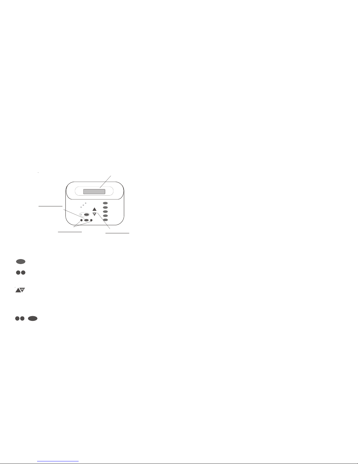
There are 5 buttons on each keypad that are used for programming (refer to diagram).
There are 4 steps to programming any function:
1.
Menu
Press the “MENU” button to get to the desired menu. Multiple pushes of the button will
rotate through all 6 menus and return to the starting point.
2.
>
>
Press either key to scroll through the various items in the selected menu. Multiple pushes
of the button will rotate through all menu items and return to the starting point. Only menu
items that are applicable to your pool will appear. (Example: if you don’t have a spa, then
no spa related menu items will appear).
3. Once a menu item has been selected above, the current setting/selection will appear (flashing)
on the display. Use the “+” and/or “-” keys to change this selection. Sometimes “+” and
“-“ will adjust a value up or down (example: heater temperature setting or timeclock on/off
time). In this case, pushing the “+” or “-” will change the value by one increment and
holding the “+” or “-” button in for more than one second will make the values auto scroll.
In other cases, the “+” and “-“ may toggle between 2 options (example: turning
superchlorination ON or OFF).
4.
>
>
Menu
After you have adjusted the item to the desired value, simply move on to the next menu
item to “lock in” your new setting. The Aqua Plus memory will maintain the setting, even
if power is removed for an extended period.
30
+
Pool/Spa
Filter
Lights
Aux 1
Aux 2
Menu
>
>
Service
+
Salt Level
3200ppm
Displa
y
“+” and “-” Buttons
Menu Button
Adust
Select Desired Menu
Select Items from
a Menu
“<” and “>” Buttons
System Maintenance
To maintain maximum performance, it is recommended that you open and visually inspect the cell every 3 months
or after cleaning your filter. The Aqua Plus will remind you to do this by displaying the message “Inspect/Clean
Cell” after approximately 500 hours of operation.
The Aqua Plus electrolytic cell has a self cleaning feature incorporated into the electronic control’s logic. In most
cases this self cleaning action will keep the cell working at optimum efficiency. In areas where water is hard (high
mineral content) or in pools where the water chemistry has been allowed to get “out of balance”, the cell may
require periodic cleaning.
Servicing and Cleaning the Turbo Cell
Turn off power to the Aqua Plus before removing the electrolytic cell. Once removed, look inside the cell and
inspect for scale formation (light colored crusty or flaky deposits) on the plates and for any debris which has
passed through the filter and caught on the plates. If no deposits are visible, reinstall. If deposits are seen, use a
high pressure garden hose and try to flush the scale off. If this is not successful, use a plastic or wood tool (do not
use metal as this will scratch the coating off the plates) and scrape deposits off of plates. Note that a buildup on the
cell indicates that there is an unusually high calcium level in the pool (old pool water is usually the cause). If this is
not corrected, you may to have to periodically clean the cell. The simplest way to avoid this is to bring the pool
chemistry to the recommended levels as specified.
Mild Acid Washing: Use only in severe cases where flushing and scraping will not remove the majority of
deposits. To acid wash, turn off power to Aqua Plus. Remove cell from piping. In a clean plastic container, mix
a 2:1 solution of water to muriatic acid (one gallon of water to two quarts of muriatic acid). ALWAYS ADD ACID
TO WATER - NEVER ADD WATER TO ACID. Be sure to wear rubber gloves and appropriate eye protection.
The level of the solution in the container should just reach the top of the cell so that the wire harness compartment
is NOT submerged. It may be helpful to coil the wiring before immersing the cell. The cell should soak for a few
minutes and then rinse with a high pressure garden hose. If any deposits are still visible, repeat soaking and rinsing.
Replace cell and inspect again periodically.
Winterizing
The Aqua Plus electrolytic cell and flow detection switch will be damaged by freezing water just as your pool
plumbing would. In areas of the country which experience severe or extended periods of freezing temperatures, be
sure to drain all water from the pump, filter, and supply and return lines before any freezing conditions occur. The
electronic control is capable of withstanding any winter weather and should not be removed.
If you are in an area that only experiences occasional freezing conditions, your Aqua Plus system may be set up to
circulate the pool water whenever the air sensor drops to the selected freeze temperature threshold. Make sure
the air sensor is recording the correct temperature and is NOT located in the direct sunlight to ensure proper freeze
protection operation.
Spring Start-up
When first starting the pool in the spring time, it is highly recommended that you temporarily set the pool and spa
chlorinator settings (Pool Sanitizer & Spa Sanitizer in the Settings Menu) to 0% (off) and then manually shock the
pool with any chlorine based shock product and balance the pool water chemistry per the levels indicated in the
Chlorinator Operation section (page 26). Make sure to check the salt and stabilizer levels and bring them up to the
recommended levels. Your local Authorized Aqua Dealer or pool store can recommend the best chemical treatment for your pool. After the water is clear and balanced, then go back and adjust the pool and spa chlorinator
settings to the appropriate levels. Test the pool chlorine level weekly and adjust the chlorinator settings up or down
accordingly.
It is usually a good idea to also inspect the cell and clean if necessary at the start of the season. See instructions
above.
Page 9
6
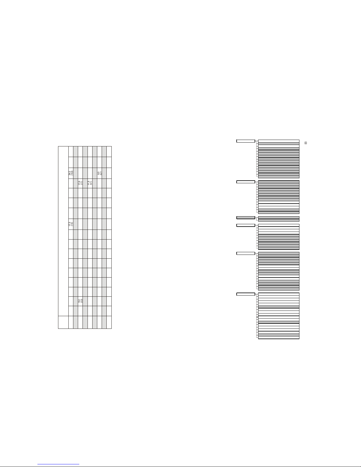
Programming Menu Flowchart
The Aqua Plus’s six menus have many items that allow you to customize the operation of your pool/spa equipment.
The chart below shows the Aqua Plus’s menus as well as each menu’s specific settings.
29
Gallons and (Liters) of Pool/Spa water
Current
Stabilizer
Level (ppm)
0 ppm
20 ppm
60 ppm
30 ppm
40 ppm
50 ppm
70 ppm
80 ppm
10 ppm
12,000
(45000)
8,000
(30000)
14,000
(52500)
10,000
(37500)
16,000
(60000)
18,000
(67500)
20,000
(75000)
22,000
(82500)
32,000
(120000)
24,000
(90000)
34,000
(127500)
26,000
(97500)
36,000
(135000)
28,000
(105000)
38,000
(142500)
30,000
(112500)
40,000
(150000)
8.0
(3.6)
5.3
(3.6)
8.0
(3.6)
8.0
(3.6)
9.4
(4.3)
6.7
(4.3)
9.4
(4.3)
10.7
(4.9)
12.0
(5.4)
12.0
(5.4)
13.4
(6.1)
14.7
(6.7)
21.3
(9.7)
16.0
(7.3)
22.7
(10.3)
18.7
(8.5)
25.3
(11.5)
20.0
(9.1)
26.7
(12.0)
7.0
)
(3.2
4.7
(3.2)
8.2
(3.7)
5.8
(3.7)
10.5
(4.8)
11.7
(5.3)
12.9
(5.9)
18.7
(8.5)
14.0
(6.4)
19.8
(9.0)
15.2
(6.9)
21.0
(9.5)
16.4
(7.4)
22.2
(10.0)
17.2
(8.0)
23.3
(10.5)
6.0
(2.7)
4.0
(2.7)
6.0
(2.7)
6.0
(2.7)
8.5
(3.9)
7.0
(3.2)
9.0
(2.2)
10.0
(4.5)
10.0
(4.5)
14.2
(6.3)
11.0
(5.0)
16.0
(7.2)
13.0
(5.9)
18.0
(8.1)
14.0
(6.4)
19.0
(8.6)
15.0
(6.8)
20.0
(9.0)
5.0
(2.3)
3.3
(2.3)
5.0
(2.3)
5.9
(2.7)
4.2
(2.7)
6.7
(3.0)
8.4
(3.8)
6.7
(3.0)
7.5
(3.4)
9.2
(4.2)
13.3
(6.0)
10.8
(4.9)
15.0
(6.7)
11.7
(5.2)
15.8
(7.1)
12.5
(5.6)
16.7
(7.5)
4.0
(1.8)
2.7
(1.8)
4.0
(1.8)
4.0
(1.8)
5.7
(2.6)
4.7
(2.1)
3.3
(2.1)
5.4
(2.4)
7.4
(3.3)
10.7
(4.8)
8.7
(3.9)
12.0
(5.4)
9.3
(4.2)
12.7
(5.7)
10.0
(4.5)
13.3
(6.0)
3.0
(1.4)
2.0
(1.4)
3.0
(1.4)
3.5
(1.6)
2.5
(1.6)
4.5
(2.0)
5.5
(2.5)
8.0
(3.6)
6.5
(2.9)
9.0
(4.1)
7.0
(3.2)
9.5
(4.3)
7.5
(3.4)
10.0
(4.5)
2.0
(.91)
1.3
(.91)
2.0
(.91)
2.8
(1.3)
2.3
(1.1)
1.7
(1.1)
2.7
(1.2)
3.3
(1.5)
3.7
(1.7)
5.3
(2.4)
4.3
(2.0)
4.7
(2.1)
6.3
(2.8)
5.0
(2.3)
6.7
(3.0)
1.0
(.45)
0.7
(.45)
1.2
(.54)
0.8
(.54)
1.4
(.64)
1.5
(.68)
1.7
(.77)
1.8
(.82)
2.7
(1.2)
2.2
(1.0)
3.0
(1.3)
2.3
(1.1)
3.2
(1.4)
2.5
(1.2)
3.3
(1.5)
0.00.0 0.00.0 0.0 0.0 0.0 0.0
0.00.0 0.00.0 0.00.0 0.00.0 0.0
denotes conditional items
default menu
dayand time
watertemperature
air temperature
chlorinator se tting
salt level
reasonpump is running (notscheduled)
inspect cell
reason hi-speed is running (notscheduled)
countdowntime remai ning
heatercontrol status
systemmanual off
check system e rror
filtervsp speed/reason
lights/auxspeed/reason
pH/ORP levels
settings menu
spa heater1temperature
poolheater1 temperature
spa solartemperature
pool solartemperature
vspspeedsettings
superchlorinate
spa chlorinatorsetting
pool chlorinatorsetting
dayand time
backlitdisplaylight
beeper
teach wirelessremote
wireless channel
maintenancemen u
pHcalibrationwizard
cleanp robewizard
timers menu
pool filter1 or hi-speed 1
poolfilter 2or lo-speed 1
pool filter3 or hi-speed 2
pool filter4 or lo-speed 2
spa
lights
aux1
aux2
valve3
superchlorinate
diagnostic menu
chlorinatordiagnostics
instantsalt
pH/orp levels
flow switch
celltemperature sensor
water/poolsensor
air sensor
solarsensor
vspspeed/power
main software revision
displaysoftwarerevision
chemistrysense module software
vspsoftware revision
RFbasesoftwarerevision
6 button spaside softwarerevision
configuration menu
chlorinator
chemistryconfig.Wizard
pool/spa
filter
heater1
solar
externalinput active state
lights
aux1
aux2
valve3
6buttonspasideremote
remote menus
7-day orweekend/weekday timeclock
12 houror 24 hour time format
ºF or ºC
vsp speed (%or rpm)
resetto default
Page 10

7
The Default Menu is a series of informative displays (temperatures, salt levels, chlorinator settings, etc.) with
nothing to set. The Aqua Plus will automatically switch to the default menu when no keys have been pressed for 2
minutes and will then scroll through each display.
The Settings Menu and the Timers Menu are the menus you will be using most often to adjust the operation of your
pool. The Configuration Menu is used when the system is installed and defines what equipment is connected to
each output and the operational logic that will control the equipment. This menu is normally “locked” and should
only be used by a pool professional. Details regarding the Configuration menu are included in both the Operation
and the Installation Manual.
The “Diagnostic Menu” is primarily intended for the service technician and contains information and details about
the system operation that are helpful in troubleshooting, if problems occur.
The “Maintenance Menu” will be displayed only if the optional AQL-CHEM is used and the Sensing System is
enabled in the Chemistry Config. Wizard. This menu is used to perform functions relating to the AQL-CHEM ORP
and pH sensing kit.
Settings Menu
The Settings Menu allows you to set all system operating parameters except the timeclock and countdown timers
which are part of the Timers Menu.
Spa Heater1
Off
Adjust the desired spa temperatu re (Off, 65°F, 66°F, ...103°F, 104°F, Off)
Move to previous/next menu item
The spa heater setting will only appear if the system has been setup for “spa only” or “pool and spa”
operation and the heater control is enabled. The heater will turn on whenever the pool/spa valves are
in the “spa only” position and the filter pump is running and the spa water temperature is less than the
desired temperature setting. If you have both solar heat and a conventional heater and the solar
priority option is selected (Configuration Menu), then the conventional heater will only operate when
solar heat is NOT available.
Pool Heater1
Off
Adjust the desired pool temperature (Off, 65°F, 66°F, ...103°F, 104°F, Off)
Move to previous/next menu item
The pool heater setting will only appear if the system has been setup for “pool only” or “pool and
spa” operation and the heater control is enabled. The heater will turn on whenever the pool/spa
valves are in the “pool only” or “spa spillover” position and the filter pump is running and the pool
water temperature is less than the desired temperature setting. If you have both solar heat and a
conventional heater and the solar priority option is selected (Configuration Menu), then the
conventional heater will only operate when solar heat is NOT available.
Spa Solar
102°F
Adjust the desired spa temperatu re (Off, 65°F, 66°F, ...103°F, 104°F, Off)
Move to previous/next menu item
The spa solar setting will only appear if the system has been setup for “spa only” or “pool and spa”
operation and the solar control is enabled. The solar system will turn on whenever the pool/spa
valves are in the “spa only” position and the filter pump is running and the spa water temperature is
less than the desired temperature setting and solar heat is available.
Pool Solar
88°F
Adjust the desired pool temperature (Off, 65°F, 66°F, ...103°F, 104°F, Off)
Move to previous/next menu item
The pool solar setting will only appear if the system has been setup for “pool only” or “pool and spa”
operation and the solar control is enabled. The solar system will turn on whenever the pool/spa
valves are in the “pool only” or “spa spillover” position and the filter pump is running and the pool
water temperature is less than the desired temperature setting and solar heat is available.
28
Gall
ons and (Liters) of Pool/Spa water
12,000 14,000 16,0 00
18,000 20,000 22,0 00 32,00024,000 34,00026,000 36,00028,000 38,00030,000 40,000
Current salt
level
(45000) (52,500) (60,000)
(67,500)(75,000) (82,500) (120,000)(90,000) (127,500)(97,500) (135,000)(105,000) (142,500)(112,500 ) (150,00 0)
ppm
0
320
(145)
373
(170)
427
(194)
480
(218)
(242)
587 854
(267) (388)
640 907
(291) (412)
693 960
(315) (436)
747
(339) (4
60)
800
1067
(364)
(484)
200
300
(136)
350
(159)
400
(182)
450
(205)
500
(227)
550 800
(250)
(363)
600 850
(273) (385)
650 900
(295) (408)
700 9
50
(318) (43
0)
750
1000
(341)
(453)
400
280
(127)
327
(148)
373
(170)
420
(191)
467
(212)
513 747
(233) (339)
560 793
(255) (360)
607 840
(276) (382)
653 88
7
(297) (4
03)
700
933
(318)
(424)
600
260
(118)
303
(138)
347
(158)
390
(177)
433
(197)
477 693
(217) (317)
520 737
(236) (337)
563 780
(256) (358)
607 8
23
(276) (3
78)
650
867
(297)
(398)
800
240
(109)
280
(127)
320
(145)
360
(164)
400
(182)
440 640
(200) (291)
480 680
(218)
(310)
520 720
(236) (328)
560 76
0
(255) (3
46)
600
800
(273)
(364)
1000
220
(100)
257
(117)
293
(133)
330
(150)
367
(167)
403 587
(183) (267)
440 623
(200) (283)
477 660
(217) (300)
513 6 9
7
(233) (3
17)
550
733
(250)
(333)
1200
200
(91)
233
(106)
267
(121)
300
(136)
333
(152)
367 533
(167) (243)
400 567
(182) (258)
433 600
(197) (274)
467 63
3
(212) (2
89)
500
667
(227)
(304)
1400
180
(82)
210
(95)
240
(109)
270
(123)
300
(136)
330 480
(150) (218)
360 510
(164) (232)
390 540
(177) (246)
420 57
0
(191) (2
59)
450
600
(205)
(263)
1600
160
(73)
187
(85)
213
(97)
240
(109)
267
(121)
293 427
(133)
(195)
320 453
(145) (207)
347 480
(158) (219)
373 50
7
(170) (2
31)
400
533
(182)
(243)
1800
140
(64)
163
(74)
187
(85)
210
(95)
233
(106)
257 373
(117) (169)
280 397
(127) (180)
303 420
(138) (190)
327 44
3
(148) (20
1)
350
467
(159)
(211)
2000
120
100
80
60
20
40
(55)
(45)
(36)
(27)
(9)
(18)
140
117
23
47
(64)
(53)
(11)
(21)
160
133
27
53
(73)
(61)
(12)
(24)
180
150
30
60
(82)
(68)
(14)
(27)
200
167
33
67
(91)
(76)
(15)
(30)
220 320
183 267
37 53
73 107
(100) (145)
(83) (121)
(17) (24)
(33) (48)
240
340
200 283
40
57
80 113
(109) (154)
(91) (129)
(18) (26)
(36) (51)
260 360
217 300
43 60
87 120
(118) (163)
(98) (137)
(20) ( 27)
(39) (54)
280 380233 31
7
47
6
3
93
1
27
(127) (172)(106) (14
4)
(21) (29)(42) (5
7)
300
400
250
333
50
67
100
133
(136)
(181)
(114)
(152)
(23)
(30)
(45)
(60)
(32)
80
(36)
90
(41)
100
(45)
110 160
(50) (73)
120 170
(55) (77)
130 180
(59) (81)
140
190
(64) (86)
150 200
(68) (90)
93
(42)
107
(48)
120
(55)
133
(61)
147 213
(67) (98)
160
227
(73) (104)
173 240
(79) (110)
187 253
(85) (117)
200
267
(91) (123)
2200
3000
2800
2400
3200
Ideal Ideal Ideal Ideal Ideal
Ideal Ide alIdeal IdealIdeal Ide alIdeal IdealIdeal I deal
2600
3400
OK
OK
OK
OK
OK OK OK
OK OKOK OKOK OKOK OKOK OK
POUNDS and (Kg) OF SALT NEEDED FOR 3200 PPM
3600+
Dilute Dilute Dilu
te Dilute Dilute Dilute DiluteDilute DiluteDilute DiluteDilute DiluteDilute Dilute
10,000
8,000
(37,500)
213
267
(97)
(121)
200 250
(91) (114)
187 233
(85)
(106)
173
217
(79)
(98)
160 200
(73)
(91)
147 183
(67) (83)
133 167
(61) (76)
120 150
(55) (68)
107 13 3
(48) (61)
93 117
(42) (53)
80 100
67 83
53
67
40 50
13 17
27 3 3
(36) (45)
(30) (38)
(24) (30)
(18) (23)
(6) (8)
(12)
(15)
Ideal
Ideal
Dilute
Dilute
(30,000)
Page 11

8
VSP Speed Settings
+ to enter
Filter Speed 1
95%
Push to access Variable Speed Pump Speed Settings
Move to previous/next confi guration menu
Spa Speed
50%
Move to next menu item
only if Pool and Spa and Filter is Variable Speed
only if an output is configured for a variable speed pump
only if Filter is Variable Speed
Set the desired Filter Speed 1 from the Filter Lowest to the Fil ter Highest
Move to next menu item
Aux1 Speed
95%
Set the desired Aux1 Speed from 10% to 100%
Move to next menu item
only if Aux2 is controlled by a variable speed pump
The Filter and up to 3 Lights and Aux outputs can be configured to control variable speed pumps.
These settings allow you to select the desired speed of the variable speed pump for each output used.
The speed can be displayed in % or RPM, whichever is selected in the Configuration Menu. When the
Filter output is on, the actual speed of the pump(s) will be dependent on the minimum and maximum
speeds set for that output in the Configuration Menu.
Super Chlorin ate
Off
Turn super chlorinate on or off
Move to previous/next menu item
This display only appears if the chlorinator function is enabled. If an AQL-CHEM is being used, super
chlorinate will not be available if chemical sensing is enabled and ORP is in Auto Sensing (see AQLCHEM manual).
When you have an unusually high bather load, a large amount of rain, a cloudy water condition, or
any other condition that requires a large amount of chlorine to be introduced to the pool, activate the
Aqua Plus Super-Chlorinate function. The Aqua Plus will turn on the filter pump, set the pool/spa
valves to the correct position, and set the chlorine generator to maximum output. The superchlorinate
function will continue for the programmed number of hours (see Timers/Super Chlorinate Hours
below) overriding the normal filter pump timeclock settings. At the end of the super chlorinate period,
the pool will return to normal operation.
If you manually turn off the filter pump (using the FILTER button on any display/keypad), the super
chlorinate function terminates. When you turn the filter pump back on, super chlorinate will resume
for the balance of the programmed number of hours.
Spa Chlorinator
3%
Adjust the desired chlorinator output for s pa (0,1,2,3...9,10,15,20...95,100%)
Move to previous/next menu item
This setting will appear only if the system has been setup for “chlorinator” and “spa only” or “pool
and spa”. If an AQL-CHEM is being used, super chlorinate will not be available if chemical sensing is
enabled and ORP is in Auto Sensing (see AQL-CHEM manual). It will determine the chlorinator output
when the system is operating in spa-only mode. The actual amount of chlorine introduced into the
spa is determined by: this setting, the amount of time the pool operates in spa-only mode, the water
temperature, and the amount of salt in the water. If the filter pump is running due to the freeze
protection feature, then the chlorinator will not operate during this time.
Pool Chlorinator
60%
Adjust the desired chlorinator outp ut for pool (0,1,2,3...9,10,15,20...95,100%)
Move to previous/next menu item
This setting will appear only if the system has been setup for “pool only” or “pool and spa”. If an
AQL-CHEM is being used, super chlorinate will not be available if chemical sensing is enabled and
ORP is in Auto Sensing (see AQL-CHEM manual). It will determine the chlorinator output when the
system is operating in pool-only or spa spillover modes. The actual amount of chlorine introduced
into the pool is determined by: this setting, the amount of time the filter pump is running, the water
temperature, and the amount of salt in the water. If the filter pump is running due to the freeze
protection feature, then the chlorinator will not operate during this time.
27
Gallons
Liters
(pool size in feet)
(pool size in meters)
Rectangular
Round
Oval
Diameter x Diameter x
Average Depth x 5.9
Length x Width x
Average Depth x 6.7
Length x Width x
Average Depth x 7.5
Diameter x Diameter x
Average Depth x 785
Length x Width x
Average Depth x 893
Length x Width x
Average Depth x 1000
The pool’s chemistry must be balanced BEFORE activating the Aqua Plus’s optional chlorinator function. NOTE:
If the pool does not have new water, add metal remover and non-copper based algaecide to the pool, per
manufacturer’s instructions. This ensures a quick, troublefree transfer to the Aqua Plus system.
Salt
Salt Level
Use the chart on the following page to determine how much salt in pounds or (Kgs) should be added to reach the
recommended levels. Use the equations below (measurements are in feet/gallons and meters/liters) if pool size is
unknown.
The operating salt level is between 2700-3400 PPM (parts per million) with 3200 PPM being optimal. Before
adding any salt, test the salt level. This is especially important for retrofit installation to older pools where chlorine
added to the pool over time has ended up as salt. If the level is low, determine the number of gallons in the pool and
add salt according to the chart below. A low salt level will reduce the efficiency of the sanitization and result in low
chlorine production. A high salt level can cause the Aqua Plus to stop chlorinating. The salt in your pool/spa is
constantly recycled and the loss of salt throughout the swimming season should be minimal. This loss is due
primarily to the addition of water because of splashing, backwashing, or draining (because of rain). Salt is not lost
due to evaporation.
Type of Salt to Use
It is important to use only sodium chloride (NaCl) salt that is greater than 99.0% pure. This can be found at most
pool stores in 40-80 lb. bags labeled “for use in swimming pools”. Alternatively, use common food quality or water
softener salt that is at least 99.0% pure. It is also acceptable to use water conditioning salt pellets, however, it will
take longer for them to dissolve. Do not use rock salt, or salt with more than 1% of yellow prussiate of soda, salt
with anti-caking additives, or iodized salt.
How to Add Salt
For new plaster pools, wait 10-14 days before adding salt to allow the plaster to cure. Turn the circulating pump
on and add salt directly into the pool. Brush the salt around to speed up the dissolving process—do not allow salt
to pile up on the bottom of the pool. Run the filter pump for 24 hours with the suction coming from the main drain
(use pool vacuum if there is no main drain) to allow the salt to evenly disperse throughout the pool. The salt display
may take 24 hours to respond to the change in salt concentration.
Always check stabilizer (cyanuric acid), when checking salt. These levels will most likely decline together. Use the
chart on page 29 to determine how much stabilizer must be added to raise the level to 80 ppm.
Page 12
9
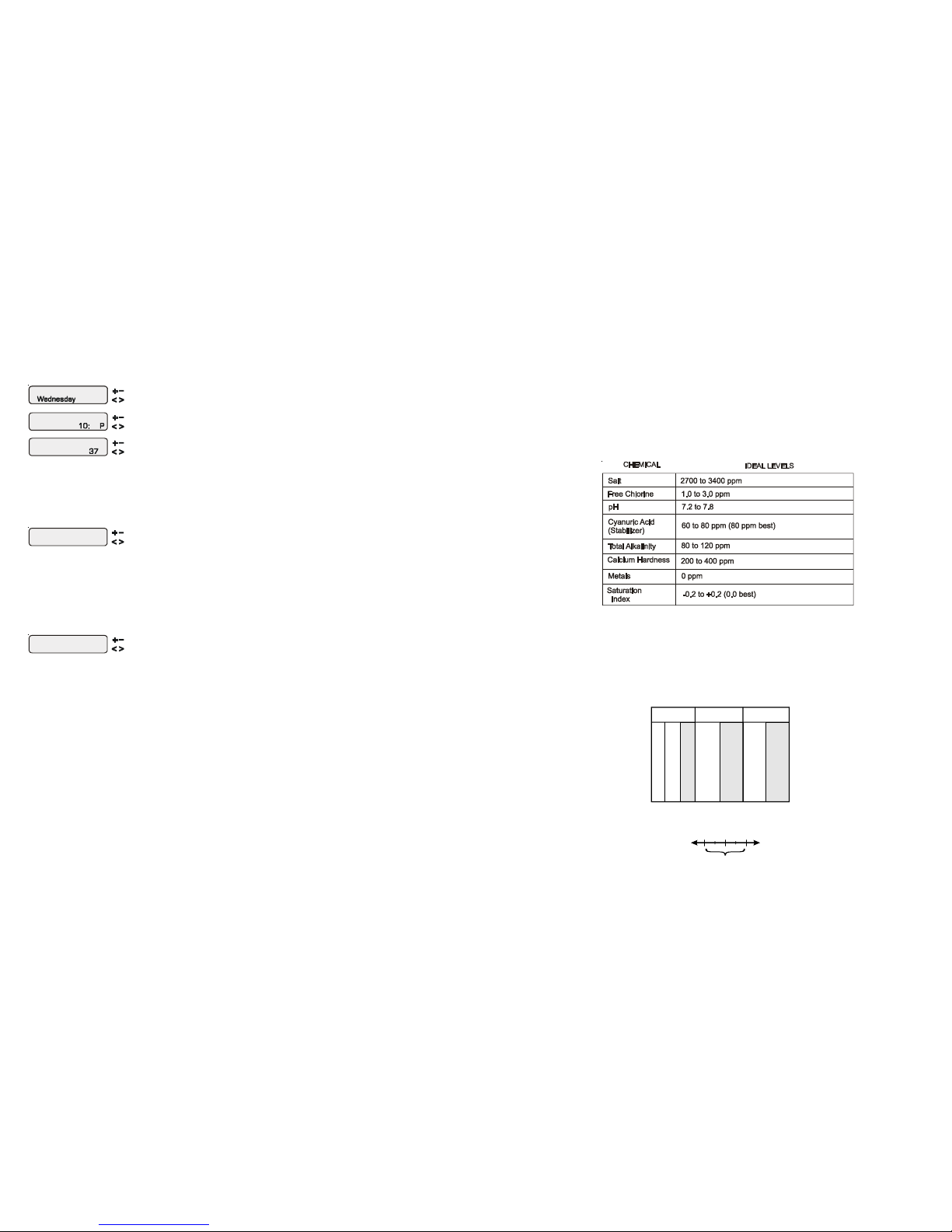
Set Day and Time
Wednesday 10:37P
Adjust the curr ent day of the week
Move to hours setting
Set Day and Time
10:37P
Set Day and Time
Wednesday 37
Set Day and Time
Wednesday 10: P
Adjust the current hour (including AM/PM if applicable)
Adjust the current minute
Move to minutes sett ing
Move to previous/next menu item
Use this function to set the current day of the week and time. These values are used for all the
automatic timeclock functions of the Aqua Plus and are also displayed as part of the default menu.
The Aqua Plus is designed to keep the clock running during power outages lasting less than 7 days.
If power has been off for longer than 7 days, then the time may have to be reset.
Display Light
On for 60 sec
Toggle between Always On and On for 60 sec.
Move to previous/next menu item
This function controls the backlight on the display. If the “60 seconds” option is selected, then the
backlight will automatically turn off 60 seconds after the last key is pressed and will stay off until next
time a key is pressed.
Note that the Display Light selection only applies to the display keypad that you are currently using.
Other display/keypads will not be affected. In other words, you need to individually set this option
for each display/keypad in the system.
Beeper
Enabled
Toggle between
Enabled (default) and Disabled Beeper
Move to next menu item
When “Enabled”, the keypad will beep every time a key is pressed. If this audible indication is not
desired, select “Disabled”.
This function only applies to the display/keypad that you are currently using. You need to set this
option for each display/keypad in your system.
NOTE: This function is not supported on all display/keypads. If the “Enabled” selection is not
blinking, then the current software revision of that particular keypad/display does not support the
option and it will default to Beeper Enabled.
26
ºC ºF Ti
Calcuim
Hardness
Ci
Tot al
Alkalinity
Ai
53
60
66
76
84
94
103
12
16
19
24
29
34
39
.3
.4
.5
.6
.7
.8
.9
How to use: Measure pool pH, t emperature, calcium hardness,
and total alkalinit y. Use the chart above to de termine Ti, Ci,and
Ai from your measurements. Inser t values of pH, Ti, Ci and Ai
into the above equation. If Si equals .2 or more, scaling and
staining may occur. If Si equals -.2 or les s corrosion or irritation
may occur.
Si = pH + Ti + Ci + Ai - 12.
1
-.2
0.2
CORROSIVE SCALING
75 75
100 100
125 125
150 150
200 200
250 250
300 300
400 400
600 600
800 800
1.5 1.9
1.6 2.0
1.7 2.1
1.8 2.2
1.9 2.3
2.0 2.4
2.1 2.5
2.2 2.6
2.4 2.8
2.5 2.9
OK
Chlorinator Operation / Water Chemistry
General Water Chemistry
Salt is required only if you are using the chlorinator features on the Aqua Plus Control. If you are NOT using the
chlorinator, it is recommended that you follow all of the other chemistry recommendations besides salt. Refer to the
description of the Aqua Plus configuration menu for information on enabling/disabling the chlorinator (see page 13).
Water Chemistry
The table below summarizes the levels that are recommended by the Association of Pool and Spa Professionals
(APSP). The only special requirements for the Aqua Plus are the salt level and stabilizer.
Saturation index
The saturation index (Si) relates to the calcium and alkalinity in the water and is an indicator of the pool water
“balance”. Your water is properly balanced if the Si is 0 ±0.2. If the Si is below -0.2, the water is corrosive and
plaster pool walls will be dissolved into the water. If the Si is above +0.2, scaling and staining will occur. Use the
chart below to determine the saturation index.
Page 13

10
Teach Wireless
+ to start
Teach
Successful
Wireless
Teach
NOT Successful
Wireless
Teach Wireless
Base NOT Found
Press and hold
wireless button
Push to start process
Move to previous/next menu item
Move to previous/next menu item
Move to previous/next menu item
Move to previous/next menu item
Move to previous/next menu item
Press any button on wireless remote
This menu will only appear if a wireless base station is connected to the Aqua Plus. Perform this
procedure each time a wireless remote control is added to the Aqua Plus system. During this procedure the wireless remote “learns” and remembers the ID code for the wireless base station connected
to this particular Aqua Plus unit and will reject messages with any other ID codes. If “Base NOT
found” is displayed, then the Aqua Plus can not communicate with the transmitter/receiver base
station attached to the main unit. If “NOT Successful” is displayed, then the base station did not
receive a signal from the remote control. This may be due to the distance between the Base Receiver
and the remote device being too great or may be due to interference caused by other RF equipment
operating in the neighborhood. Try changing the channel and then repeat the “Teach Wireless”
command.
Wireless
Channel: 1
Reteach all
wireless units
Confirm Change:
+ to proceed
Push to confirm the channel change
Change the desired w ireless channel (1 - 5)
Move to previous (Teach Wireless) menu
If channel is changed, move to confir mation menu
Move to previous/next menu item
If channel is not changed, move to prev ious/next menu item
This setting changes the channel to be used by the wireless base station and remote(s). If the channel
is changed and confirmed, all of the wireless remotes will have to be retaught. This menu will only
appear if a wireless base station is connected to the Aqua Plus.
Timers Menu
The Timers Menu allows you to set all timeclock and countdown timers which control the automatic operation of
your pool/spa system.
Each timeclock has a single on/off program per day. All of the timeclocks are setup (Configuration Menu) either as
“all days” or “weekends/weekdays”. If “weekends/weekdays” are selected, you will need to program on times for
both weekdays and weekends and off times for both weekdays and weekends, even if you want them to be the
same. All times are adjusted in 15 minute increments (9:00A, 9:15A, 9:30A, etc.). If you program the on time
equal to the off time (“10:00A to 10:00A”) the output will NEVER turn on. If you want to disable a timeclock, you
can set the on time equal to the off time and you will notice the times disappear and the display simply shows “Off”.
If, at a later time, you wish to re-activate the timeclock, simply press either the “+” or “-” buttons to go back to a
normal timeclock programming display.
The Countdown timer is programmed in increments of 5 minutes from “Manual On/Off” (0 minutes) to a maximum
of “21:00” (21 hours). When “Manual On/Off” is displayed, the countdown timer is disabled and the output will be
manually controlled. When a countdown timer is equal or greater than “0:05”, pressing the appropriate output
button will turn the output on and start the timer. Pressing the button again will turn the output off or, when the
programmed time has elapsed, the output will automatically turn off.
25
Note: Separate chlorinator output levels for the pool and spa must be set. If the valves are in
the pool-only or spa spillover positions, then the chlorinator will operate according the pool
setting. If the valves are in the spa-only position then the chlorinator will operate according to
the spa setting. The actual amount of chlorine introduced into the pool/spa is determined by:
this output setting, the amount of time the filter pump is running, the water temperature, and
the amount of salt in the water. Also see Start/Stop Superchlorination.
Start/Stop Superchlorination
1. Press the “MENU” button repeatedly until “Settings Menu” is displayed
2. Press the “>” button repeatedly until “Super Chlorinate” is displayed.
3. The display will show whether superchlorination is “on” or “off”.
4. Press “+” or “-“ to toggle between “on” and “off”
Note: Once started, superchlorination will run for the programmed number of hours (Timers
Menu/Super Chlorinate Hours) or until you manually turn it off. Superchlorination may be
temporarily interrupted for a programmed spa operation.
Program a Timeclock
1. Press the “MENU” button repeatedly until “Timers Menu” is displayed
2. Press the “>” button repeatedly until “xxx—all” or “xxx—wkend” (where xxx is the parameter that
you want to program) is displayed.
3. Use the “+” and “-“ buttons to set the desired start time, then press “>” to switch to the off time. Use
the “+” and “-“ buttons to adjust the off time. If you are setting the “weekend” timeclock, press “>” to
go to the “weekday” settings.
Note: During the programmed time, there may be other automatic or manual operations that
prevent the relay/valve from operating—see a more detailed discussion under Automatic System Operation/Timers Menu/Aux Timeclock or in Troubleshooting/Diagnostic Information.
Program a Countdown Timer
1. Press the “MENU” button repeatedly until “Timers Menu” is displayed
2. Press the “>” button repeatedly until the “xxx—Timer” (where xxx is the parameter that you want to
program) is displayed.
3. Use the “+” and “-“ buttons to set the desired timer period.
Note: A setting of 0:00 will display as “manual on/off”. The countdown automatic turn off
function is disabled but manual operation is still permitted. There may be other automatic or
manual operations that prevent the relay/valve from operating—see a more detailed discussion
under Automatic System Operation/Timers Menu/Aux Timeclock or in Troubleshooting/Diagnostic Information.
Enter/Exit Service (or Service—Timed) Mode
1. Go to Aqua Plus main unit (normally mounted near the pool equipment)
2. Pressing the “Service” button rotates through normal operation (red LED off), service mode (red
LED on continuously) and service-timed mode (red LED flashing).
Note: This operation can only be performed at the main Aqua Plus unit. Both “Service” and
“Service-Timed” disable all automatic programmed operations and allow manual operation
from the main unit only. The buttons on the remote display/keypads will still be able to turn
equipment off in case of an emergency, but will not turn any equipment on. If the system is in
“Serviced-Timed” it will automatically switch back to normal operation at the end of the 3
hour time period.
Page 14

11
For one speed pumps, this is the first filter timeclock and will determine the normal hours of filtration
for the pool. For pool/spa combination systems with spillover enabled, the valves will automatically
switch to spillover mode at the start of the filtration period. For all other systems, the valves will
switch to the pool-only position.
For two speed, this setting will be the period of time when the pump runs at high speed (the word
“Filter T1” in the display will be replaced with “Filter Hi”). There is a separate timeclock for the low
speed operation (see “Filter T2” below). If the high speed and low speed periods overlap, then the
pump will operate in low speed during the overlap period.
For a variable speed pump, this setting will be the period of time when the pump will run at the speed
selected for speed1 in the settings menu. If there is an overlap in any of the timeclocks, then the lower
number timeclock/speed has priority.
Depending on the type of filter pump used, there are several reasons why the pump may be running
at times other than the timeclock period set above. These include super-chlorination, spa operation,
manual operation, heater cooldown, freeze protection, heater-extend and solar-extend. For variable
speed pumps, when there is more than one reason for the pump to run, the speed priority in order from
highest to lowest is priming (first 3 minutes after filter has been turned on), freeze protection, group,
heater minimum, aux/valve override, spa mode, speed1, speed2, speed3, speed4. Note that the reason
for the current speed is shown in the Default Menu.
For one speed pumps, this is the second filter timeclock
For two speed pumps, this timeclock will set the normal time period for filter pump low speed operation
(the word “Filter T2” in the display will be replaced with “Filter L1”). If the filter pump was off prior to
the start of this time period, the filter pump will first turn on at high speed for 3 minutes to prime and
establish water flow. Afterwards, it will drop down to low speed for the remainder of the programmed
low speed time period. While this time clock will override the high speed timeclock (see above), there
are several reasons why the pump will automatically switch to high speed operation during this
programmed time period. These include manual operation, spa operation, or heating operation. Refer
to page 10 for general notes regarding timeclock programming.
For a variable speed pump, this setting will be the period of time when the pump will run at the speed
selected for speed2 in the settings menu. If there is an overlap in any of the timeclocks, then the lower
number timeclock/speed has priority.
NOTE: The third and forth filter timeclocks function similarly to the first and second (respectively). Program these timeclocks
in the same manner.
24
Set Day and Time
Wednesday 10:37P
Adjust time setting
Move between start and stop times & to previou s/next menu item
Filter T1-all
8:30A to 4:00P
Filter T1-wkend
8:30A to 4:00P
Filter T1-wkda y
8:30A to 4:00P
Adjust time setting
Adjust time setting
Move between start and stop times & to previou s/next menu item
Move between start and stop times & to previou s/next menu item
or
Set Day and Time
Wednesday 10:37P
Adjust time setting
Move between start and stop times & to previou s/next menu item
Filter T2
8:30A to 4:00P
-all
Filter T2-wkend
8:30A to 4:00P
Filter T2-wkday
8:30A to 4:00P
Adjust time setting
Adjust time setting
Move between start and stop times & to previou s/next menu item
Move between start and stop times & to previou s/next menu item
or
Quick “How To” Guide
Operate the Spa—Manually
1. Press the “Pool/Spa” button to go to “spa-only” operation (right LED illuminated). In some cases,
this may take more than one press of the button.
2. If the filter pump is not already on, press the “FILTER” button to turn it on.
3. If the spa is below the desired temperature, the heater will turn on automatically when the filter pump
is on and the valves are in the spa-only position. If you have not already set the desired temperature
for the spa, see “Set Heater Temperature” below
4. If the spa has a separate jet pump and or blower, determine if the jet pump/blower is controlled by
Aux1 or Aux2 (it should be marked on the label inside the door). Then press the appropriate button
to turn on the jets/blower.
Operate the Spa—Automatically
1. Press the “MENU” button repeatedly until “Timers Menu” is displayed
2. Press the “>” button repeatedly until the “Spa—all” or “Spa—wkend” is displayed.
3. Use the “+” and “-“ buttons to set the desired start time, then press “>” to switch to the off time. Use
the “+” and “-“ buttons to adjust the off time. If you are setting the “weekend” timeclock, press “>” to
go to the “weekday” settings.
Note: During the programmed spa time, the valves will automatically switch to the “spa-only”
position, the filter pump will turn on, and, if the spa is not up to the desired temperature, the
heater will start. This operation is the highest priority and will take precedence over other
automatically programmed operations. At the end of the spa period, the Aqua Plus will return
to its normally programmed operation state.
Set the Heater Temperature (or turn heater permanently off)
1. Press the “MENU” button repeatedly until “Settings Menu” is displayed
2. Press the “>” button repeatedly until the “Spa Heater1” or “Pool Heater1” is displayed.
3. Press the “+” or “-“ buttons repeatedly to adjust the temperature. If you adjust the temperature below
65ºF or above 104°F the display will indicate “off” and the heater will not operate regardless of
temperature.
Note: Separate temperatures for the pool and spa must be set. If the valves are in the pool-only
or spa spillover positions, then the heater will use the pool setting. If the valves are in the spaonly position then the heater will operate according to the spa setting.
Set the Chlorinator Output
1. Press the “MENU” button repeatedly until “Settings Menu” is displayed
2. Press the “>” button repeatedly until the “Spa Chlorinator” or “Pool Chlorinator” is displayed.
3. Press the “+” or “-“ buttons repeatedly to adjust the setting. If you adjust the setting to 0% the
chlorinator will be off all the time.
NOTE: After the ideal setting has been found, you may need to raise the setting when the pool
water temperature increases significantly, when there is higher than normal bather load or
when your chlorinator cell ages. You may need to lower the setting when the pool water
temperature decreases significantly or there are long periods of inactivity.
Page 15
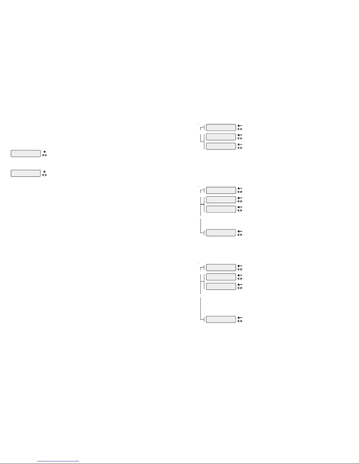
12
This menu is only available if the system has been setup for “pool and spa”. During the programmed
spa time, the Aqua Plus will turn on the filter pump and move the pool/spa valves into the “spa-only”
position. The heater will automatically heat the spa up to the programmed spa temperature (page 7).
This programmed spa operation will take precedence over all other automatic functions, only manual
operation of the filter button or pool/spa valve button will override this function.
If your pool has a separate jet pump or blower controlled by Aux1 and/or Aux2 , you will have to
program those separately.
This menu will appear only if the Lights are configured for timeclock. The lights will turn on and off at
the designated times. The only override on this function is manual on/off control by the “Lights”
button.
This menu will appear only if the Lights are configured for countdown timer. This setting is the time
after you manually turn on the lights until the Aqua Plus automatically turns off the lights. You can
also manually turn off the lights at an earlier time by pressing the LIGHTS button. If the Lights relay
is on during the programmed off time, it may be because of freeze protection.
Aux1 and Aux2 configurations are identical.
This menu will appear only if the Aux1 is configured for timeclock. The Aux output will turn on and off
at the designated times. If the Aux relay is off during the programmed on time— note that some pool
equipment (example pressure side pool cleaner) can only be operated when the filter pump is running
and the pool/spa valves are in the pool-only position—the Aqua Plus will keep the relay off until these
other conditions are suitable for operation. If the Aux relay is on during the programmed off time, it
may be because of freeze protection. Also, manual operation overrides the timeclock.
This menu will appear only if the Aux1 is configured for countdown timer. This setting is the time after
you manually turn on the Aux relay until the Aqua Plus automatically turns off the relay. You can also
manually turn off the relay at an earlier time by pressing the AUX1 button.
23
Maintenance Menu (only displays if Sensing System is enabled)
The Maintenance Menu will be displayed only if the optional AQL-CHEM is used and the Sensing System is
enabled in the Chemistry Config. Wizard. This menu is used to perform functions relating to the AQL-CHEM ORP
and pH sensing kit.
pH Calibration
Wizard, + to enter
Push to access pH Calibration Wizard
Move to previous/next menu item
Use this Wizard to calibrate the AQL-CHEM’s pH probe. This requires a manual pH test of the pool
water using a dependable red phenol test kit.
Clean Probe Wiza rd
+ to enter
Push to access Clean Probe Wizard
Move to previous/next menu item
Use this Wizard to clean the AQL-CHEM’s ORP and pH probes. The probes must be clean and free
from oil, chemical deposits and contamination to function properly. Slow response, increased need to
calibrate, and inconsistent readings are indications that the probes need to be cleaned.
Set Day and Time
Wednesday 10:37P
Adjust time setting
Move between start and stop times & to previou s/next menu item
Spa-all
6:00P to 9:00P
Spa-wkend
6:00P to 9:00P
Spa-wkday
6:00P to 9:00P
Adjust time setting
Adjust time setting
Move between start and stop times & to previou s/next menu item
Move between start and stop times & to previou s/next menu item
or
Set Day and Time
Wednesday 10:37P
Adjust time setting
Move between start and stop times & to previ ous/next menu item
Lights-all
8:00P to 11:00P
Lights-wkend
8:00P to 11:00P
Lights-wkday
8:00P to 11:00P
Adjust time setting
Adjust time setting
Move between start and stop times & to previ ous/next menu item
Move between start and stop times & to previ ous/next menu item
or
or
Lights-CountDn
0:20
Adjust time sett ing (Manual On/Off, 0:05, 0:10, 0: 015...)
Move to previous/next menu item
Set Day and Time
Wednesday 10:37P
Adjust time setting
Move between start and stop times & to previ ous/next menu item
Aux1-all
8:30A to 4:00P
Aux1-wkend
8:30A to 4:00P
Aux1-wkday
8:30A to 4:00P
Adjust time setting
Adjust time setting
Move between start and stop times & to previ ous/next menu item
Move between start and stop times & to previ ous/next menu item
or
or
Aux1-CountDn
0:20
Adjust time sett ing (Manual On/Off, 0:05, 0:10, 0: 15...)
Move to previous/next menu item
Page 16
13
This menu will appear only if Valve3 is configured for timeclock. The valve will rotate on and off at the
designated times. There is no manual override. If the Valve3 relay is on during the programmed off
time, it may be because of freeze protection.
Super Chlorin ate
24 hours
A
djust Superchlorina tion period (1 - 96 hours)
Move to previous/next menu item
For larger pools or when you have an unusually high bather load, a large amount of rain, a cloudy
water condition, or any other condition that requires a large amount of chlorine to be introduced to the
pool, may require more hours of Superchlorination. Smaller pools require less hours of
Superchlorination.
Configuration Menu Items
Each item needs to be programmed and may contain additional sub-menu items. Refer to the following pages for
information on programming.
Cell Type
T- CE LL- 15
Rotates between avai lable Cell types
Move to next menu item
Move to next menu item
Chlorinator
Enabled
Display
Salt
Chlor. Config.
+ to view/change
Toggle between Display Salt (default) and Minerals
Toggle between Chlorinator Ena bled and Disabled (def ault)
Move to previou s/next configuration menu
Move to next configura tion menu
Push to access Chlorinator option
Cell Type
T- CE LL- 15
Chlorinator
Enabled
Display
Salt
Chlor. Config.
+ to view/change
Chlorinator
The Aqua Plus is shipped with the chlorinator enabled. The cell and flow switch must be installed and
the Aqua Plus will automatically chlorinate both the pool and spa according to the desired output
setting (see Settings Menu in the Operation manual). If disabled, all displays relating to the chlorinator
will be suppressed.
When the chlorinator is enabled, the Aqua Plus will automatically detect and control any Aqua Rite(s)
that is installed in the system.
Display
Allows for the display of salt (default) or mineral values.
Cell Type Selection
The Cell Type Menu appears after “Display Salt/Minerals” in the Chlorinator Configuration Menu.
The options are T-CELL-15 (default), T-CELL-9, T-CELL5 or T-CELL-3. Make the proper selection
based on the chlorinator cell that is used in your system (the Aqua Plus includes the T-CELL-15). Refer
to the information below.
"T-CELL-3" = T-CELL-3, GLX-CELL-3-W
"T-CELL-5" = GLX-CELL-5, GLX-CELL-5-W
"T-CELL-9" = T-CELL-9, GLX-CELL-9-W
"T-CELL-15" = T-CELL-15, GLX-CELL-15-W
Chemistry Config.
Wizard + to enter
Press to access Chemistry Config. Wizard
Move to previous/next menu item
Chemistry Configuration Wizard
Requires use of the optional AQL-CHEM Sensing Kit. Following the steps of the Chemistry Config.
Wizard will set up the AQL-CHEM to sense ORP and pH levels and, if chlorination is used, can
configure the Aqua Plus to generate the correct amount of chlorine to properly sanitize the pool. Refer
to the AQL-CHEM manual for more detailed information.
22
Set Day and Time
Wednesday 10:37P
Adjust time setting
Move between start and stop times & to previ ous/next menu item
Val ve3- all
8:30A to 4:00P
Adjust time s
Val ve3- wken d
8:30A to 4:00P
Valve3-wkday
8:30A to 4:00P
Adjust time setting
Adjust time setting
Move between start and stop times & to previ ous/next menu item
Move between start and stop times & to previ ous/next menu item
or
6B Spa Config.
+ to view/change
6B A, Button 1
Pool/Spa
Select 6B Spa
A
Push to access the 6 Button Spa Side Remote opt ions
Rotates between Sy stem Off, Pool/Spa, Filter, Lights, Hea ter1,
Aux1 and Aux2
Rotates between a ll available remotes
Move to previous/next confi guration menu
Move to previous/next menu item or next configuration menu
Move to next menu item
if AQL-SS-6B i s connected
Select 6B Spa
This menu only appears if more than one AQL-SS-6B is detected at power up. Select which of the
available remote controls (A, B or C) is to be configured.
6B A, Button 1
This menu allows the user to map each button of the AQL-SS-6B to one of the standard Aqua Plus
functions. The default selections are: Button 1 - Pool/Spa, Button 2 - Filter, Button 3 - Lights, Button
4 - Heater1, Button 5 - Aux1 and Button 6 - Aux2.
Remote Menus
Enabled
Toggle between Enabled (default) and Disabled Remote Menus
Move to previous/next config uration menu
This feature will prevent unauthorized access to the Settings, Timers, and Configuration menus from
any of the Aqua Plus’s remote display/keypads. When disabled, the remote display/keypads will only
show the default menu and allow on/off control via the pushbuttons. Note that the function of the
Aqua Plus’s built-in display/keypad is unchanged by this selection. Once disabled, the only way to
enable “Remote Menus” is to use the local display/keypad.
All Timeclocks
7-day
Move to previous/next configuration menu
Toggle between 7-day (default) and Weekend/Weekday time options
This selection affects ALL of the timeclock logic in the Aqua Plus. If “7-day” is selected, each
timeclock will have one set of turn-on/turn-off settings that operate every day of the week. If “Weekend/
Weekdays” option is selected then the user can enter one set of turn-on/turn-off times for the weekend
(fixed as Saturday/Sunday) and another set of turn-on/turn-off times for weekdays (Monday through
Friday).
Time Format
12 hour AM/PM
Units
ºF and PPM
Move to previous/next configur ation menu
Move to previous/next configur ation menu
Toggle between 12 hour AM/PM (default) and 24 hour time format options
Toggle between ºF and PPM (default) and ºC and g/L (Metric) options
VSP Speed
%
Toggle between % and RPM
Move to
previous/next configuration menu
if any output is configured as a
variable speed pump
This is the unit of measure for displaying the speed of the variable speed pump. Select % of maximum
speed (3450 RPM) or revolutions per minute (RPM).
Reset Config. to
Default Press +
Are you sure?
+ to proceed
Config. reset
Confirmed
Initiate reset of all configuration parameters
Reset all configuration par ameters
Move to previous/next configuration
menu (config. not reset)
Move to previous/next menu (confi g. not reset)
Move to previous/next configuration menu
Use this function to erase all previous system configuration and reset all configuration parameters
back to the factory default values. This function is NOT reversible--be careful.
Page 17
14
Pool/Spa Config.
+ to view/change
Pool/Spa Setup
Pool and Spa
Spa Spillover
Enabled
Filter Operatio n
Spa Spillover
Push to access Pool/Spa options
Rotates between Pool O nly (default), Spa Only and
Pool and Spa
Toggle between Enabled and Disabled Spa Spillover
(default)
Toggle between Pool Only and Spa Spillover options
(default)
Move to previous/next configur ation menu
Move to next menu item
Move to next menu it em or previous/ne xt configuration menu
Move to previous/next configur ation menu
if “Pool and Spa” is selected and
if “Spa Spillover” is enabled
Spa - CountDn
00:30
Adjust time setting (Manual On/Off, 0:05, 0:10, 0:15... , (default is 4:00))
Move to next menu item
if “Pool and Spa” is selected
if “Pool and Spa” is selected
V1=Aux1, V2=Aux2
Disabled
Toggle between Enabled and Disabled
(default)
if “Pool Only” or “Spa Only” is selected
Move to previous/next configur ation menu
Filter Off Valve
Change: Enabled
Toggle between Enabled and Disabled (default)
if “Pool and Spa” is selected
Move to previous/next configur ation menu
Pool/Spa Setup
If “Pool Only” or “Spa Only” are selected, then the pool/spa valves are not needed and pushing the
POOL/SPA button on the display/keypad will have no effect. If “Pool and Spa” is selected, then the
pool/spa suction and return valve actuators should be connected to the Aqua Plus. Pressing the
POOL/SPA button on the display/keypad will allow the homeowner to alternate between pool and spa
operation.
Spa CountDn
This menu will appear only if Pool/Spa Setup is set to “Pool and Spa”. This setting is the time, after
you manually switch the Pool/Spa valves to “Spa Only”, until the Aqua Plus automatically returns the
valves to their previous positions. It is programmed in increments of 5 minutes, from “Manual On/Off”
(0 minutes) to “21:00” (21 hours). The filter is forced on during this time period.
Spa Spillover
When spa spillover is “Enabled” and “Pool and Spa”, the homeowner will be able to rotate through
“Pool Only” (both suction and return valves switched to pool), “Spa Only” (both suction and return
valves switched to spa) and “Spillover” (suction valve switched to pool and return valve switched to
spa) by successive presses of the “Pool/Spa button.
Filter Operation
If “Spa Spillover” is selected, the Aqua Plus will automatically switch the pool/spa suction and return
valves to “spillover” at the start of the programmed pool filtering time period or when the superchlorinate function is turned on. The valves will remain in this position for the remainder of the superchlorinate period. This option is usually preferable because both the pool and spa water will be
filtered and sanitized.
If “Pool Only” is selected, then the Aqua Plus will switch the pool/spa valves to the “pool only”
position at the start of the programmed pool filtering time period or when the super-chlorinate function is turned on. This may be desirable on some systems with in-floor cleaners because it allows the
cleaner to operate all the time the pool is being filtered and/or the super chlorinate is running.
V1=Aux1, V2=Aux2
This menu appears only if the Pool/Spa Setup is “Pool Only” or “Spa Only”. When enabled, Valve 1
(return) will follow the Aux1 output and Valve 2 (suction) will follow the Aux2 output. When disabled
(default), the return and suction pool/spa valves function normally.
Filter Off Valve Change
This menu appears only if Pool/Spa setup is set to “Pool and Spa - Std”. When enabled (default), the
filter pump will shut off for 35 seconds whenever the Pool/Spa valves are turning. The pump will NOT
shut off when a heater is in Heater Cooldown mode.
21
Val ve3
Disabled
Freeze
Toggle between Enabled and Disabled (default) Valve3 Freeze
Move to previous/next configur ation menu
for all functions except super chlorinate
Valve3 Config.
+ to view/change
Valve3 Function
Solar
Push to access Val ve3 options
Rotates Timeclock (default ), Solar, In-floor Cleaner and Super Chlor inate
Move to previous/next configur ation menu
Move to next menu item
Val ve3
Disabled
Interlock
Toggle between Enabled and Disabled (de fault) Valve3 Interlock
Move to next menu item
for all fu nctions except s olar and super c hlorinate
for all fu nctions except s olar and super c hlorinate
Val ve 3 E xt In put
Disabled
Toggle between Enabled and Disabled (de fault)
Move to previous/next configur ation menu
if filter pump is set to vari able speed
and the relay type is set to standard
Val ve 3 P ump Spd
Settings Menu
Select Settings Me nu (default) or desired pump speed ( Filter Lowest to Highest)
Move to previous/next configur ation menu
Valve3 Function
Timeclock (default) – the valve turns on/off at the times set for the valve3 timeclock in the Timers
Menu (see Operations Manual). The VALVE3 button can also be used to turn the valve output on or
off.
Solar – the valve operates when the filter pump is running and solar heat is available and the water is
less than the desired temperature setting. Solar heating must be enabled in the “Solar Config. menu
for proper operation to occur.
In-Floor Cleaner – the valve switches the water returning to the pool between the in-floor cleaner and
the normal return jets which facilitate efficient surface skimming. The valve will operate the in-floor
cleaner for the first half of each clock hour and then switch to the jets/skimming for the last half of the
hour.
Super Chlorinate – if “Chlorinator” is enabled, this option allows the user to start a Super Chlorinate
cycle when the Valve3 button is pressed, rather than using the Settings Menu. Note that only one
button can be assigned to this function.
Valve3 Interlock
If “Enabled”, this feature will override the function (timeclock or in-floor cleaner) selected above and
turn the valve off when: the filter pump is off, first 3 minutes of filter pump operation (allows the pump
to prime and get water flowing), or for the first 3 minutes after solar turns on (allows air in the solar
panels to be purged). Interlock is not available for solar or super chlorinate.
Valve3 External Input Interlock
When Valve3 External Input Interlock is enabled, the Valve3 output will be forced off when the external
input is active. This will have precedence over freeze protection. Valve3 External Input Interlock is not
available for solar and super chlorinate.
Valve3 Freeze Protection
This function protects the pool and plumbed equipment against freeze damage. If Freeze Protection
is enabled and the AIR temperature falls sensor falls below the selected freeze temperature threshold,
the Aqua Plus will turn on the valve to allow circulation of the water. IMPORTANT: this only enables
operation of the valve3 output during freeze--see the “Filter Pump Config.” menu to enable freeze
protection for the main circulation system.
Valve3 Pump Speed
This is the speed of the pump when the Valve3 output is on. The default selection is “Settings Menu”.
This is the speed of the pump that has been selected in the Settings Menu for normal filter operation.
If an alternate speed is desired when the Valve3 output is on, push “+” or “-” and select from “Filter
Lowest” to “Filter Highest” in 5% increments.
Page 18

15
Filter Confi g.
+ to view/change
Filter Pump
1 Speed
Freeze Protect
Enabled
Lowest Speed
10%
Highest Speed
100%
Push to access pump options
Rotates between 1-speed (defaul t), 2-speed and variabl e speed options
Toggle between Enabled (default) and Disabled Freeze Prote ction
Adjust the lowest speed desired for variable speed operati on
Adjust the highes t speed desired for variable spee d operation
Move to next menu item
Move to previous/next config uration menu
Move to next menu it em or previous/next configuration menu
Move to next menu item
Move to next menu item
if “Variable Speed” is selected
if “Variable Speed” is selected
Freeze Temp
38ºF
Freeze Protect
High Speed
Adjust the desire d freeze protection temperature (33ºF - 42ºF)
Toggle between high speed (default) and low speed
Select the desired Freeze Protec tion speed from Filter Lowes t to Filter Highest speed
Move to next menu item
Move to next menu item
Move to next menu item
if “Freeze Protect” is enabled
if “Freeze Protect” is enabled
and “2-speed Filter” is selected
if “Freeze Protect” is enabled
and “Variable Speed” is selected
External Input
Disabled
Toggle between Enabled and Disabled ( default)
Move to previous/next config uration menu
Filter Pump
For 2-speed pumps: When a 2-speed pump is configured, one of the AUX relays must also be
configured to control the low speed motor winding on the pump. Refer to the appropriate sections in
the Installation manual for specific information regarding the control logic for 2-speed and variable
speed pump operation.
For the Hayward variable speed pump: The Filter relay is used to supply input power to the pump.
The relay will be on when the filter pump output is on. When the filter pump output is off, the relay will
be off. On , off and speed is controlled by commands sent to the pump.
Lowest Speed
This is the lowest speed that the variable speed pump is allowed to run at. It is used as the lower limit
in the Low Speed Settings Menu. Set lowest speed from 10% (default) to 50%.
Highest Speed
This is the highest speed that the variable speed pump is allowed to run at. It is used as the upper limit
in the High Speed Settings Menu. Also, this is the speed that the pump will run at during the first 3
minutes of operation anytime the pump has been off for more than 30 seconds. Set highest speed from
20% to 100% (default).
Freeze Protection
Freeze protection is used to protect the pool and plumbed equipment against freeze damage. If freeze
protection is enabled and the AIR temperature sensor falls below the freeze threshold (see below), the
Aqua Plus will turn on the filter pump to circulate the water. If “Pool and Spa” is selected in the Pool/
Spa sub-menu (see page 18), the valves will also alternate between the pool and spa every 30 minutes
and the filter pump will turn off while the valves are turning. The chlorinator will not operate if freeze
protection is the only reason the pump is running.
Freeze Protection Speed
This menu only appears if freeze protection is enabled and the pump is configured for 2-speed or
variable speed pump operation. If the pump turns on due to freeze protection only, the pump will run
at this speed.
2-Speed pumps: Select high (default) or low speed operation.
Variable Speed pumps: Select the desired speed (from Filter Lowest to Filter Highest speed).
20
Countdown Timer – the aux relay will turn on when the AUX button is pressed and then will turn off
automatically after a programmed time (see Timers Menu, Operation Manual). The AUX button can
also be used to turn the output off.
Low Speed of a 2-speed Filter Pump – the Aqua Plus will operate the aux relay whenever the low
speed operation of the filter pump is required. It is very important that the “2-speed” filter pump
option be selected under the “Filter Config.” Menu for proper operation.
Timeclock – the aux relay will turn-on and turn-off at the times set for the aux1 timeclock in the Timers
Menu. The AUX button can also be used to turn the output on and off.
Solar – the aux relay operates a solar booster pump which will turn on when the filter pump is running
and solar heat is available and the water is less than the desired temperature setting. It is important to
note that “Solar Control” must be enabled in the “Solar Config.” menu for proper operation to occur.
Super Chlorinate – if “Chlorinator” is enabled, this option allows the user to start a Super Chlorinate
cycle when the Aux button is pressed, rather than using the Settings Menu. Note that only one
button can be assigned to this function.
Aux1 Relay
This feature allows the user to select either “Standard” (default), “Dimmer” or “VSP” type relay for the
Aux1 output. The optional AQL-DIM dimmer kit must be installed if “Dimmer” is desired.
When “Dimmer” is selected, and the Aux1 output is manually turned on, the “+” and “-” buttons
adjust the level from 20% to 100% (default). The level is saved for the next time the aux1 output is
turned from off to on.
If “VSP” is selected, the Aux relay is used to supply power to a Hayward Variable Speed Pump (VSP).
The relay will be on when the Aux output is on and off when the output is off. On, off and speed are
controlled by commands sent to the VSP.
Aux1 Interlock
If “Enabled”, this feature will override the function (Manual On/Off, Countdown Timer, Timeclock),
selected above and turn the aux1 off when: filter pump is off, first 3 minutes of filter pump operation
(allows the pump to prime and get water flowing), when the pool/spa suction return valves are in any
position other than “pool only”, or for the first 3 minutes after solar turns on (allows air in the solar
panels to be purged). Interlock is not available for solar, low speed filter pump, super chlorinate or
dimmer.
Aux1 External Input Interlock
When Aux1 External Input Interlock is enabled, the Aux1 output will be forced off when the external
input is active. This will have precedence over freeze protection. Aux1 External Input Interlock is not
available for solar, low speed filter pump, dimmer, group, super chlorinate, or pH dispense functions.
Aux1 Freeze Protection
This function protects the pool, plumbing, and equipment against freeze damage. If Freeze Protection
is enabled and the AIR temperature sensor falls below the selected freeze protection temperature, the
Aqua Plus will turn on the aux relay to circulate the water. IMPORTANT: this only enables operation
of the AUX output during freeze--see the “Filter Pump Config.” menu to enable freeze protection for
the main circulation system. Freeze Protection is not available for low speed filter pump, dimmer,
group, super chlorinate or pH dispense functions.
Aux1 Pump Speed
This is the speed of the filter pump when the Aux1 output is on. The default selection is “Settings
Menu”. This is the speed of the pump that has been selected in the Settings Menu for normal filter
operation. If an alternate speed is desired when the Aux1 output is on, push “+” or “-” and select from
“Lowest” to “Highest” in 5% increments.
Page 19
16
Freeze Protection Temperature
Select the temperature to be used for freeze protection. Temperature is adjustable from 33ºF-42ºF (1ºC6ºC). 38ºF (3ºC) is default. This threshold will be used for all outputs that have freeze protection
enabled.
External Input Interlock
When enabled, the filter pump will be forced off when the external input is active. Note that freeze
protection will have precedence over this feature.
Heater1 Config.
+ to view/change
Heater1
Disable
Heater1 Cooldown
Disabled
Heater1 Extend
Disabled
Push to acces s heater options
Toggle between Enabled and Disabled (default) Heat er 1
Toggle between Enabled and Disabl ed (default) Heat er 1 Cooldown
Toggle between Enabled and Disabled (default) Heat er 1 Extend
Move to previ ous/next configuration menu
Move to next menu item or pr evious/next conf iguration menu
Move to next menu item
Move to previ ous/next configuration menu
if “Heater1” is enabled
if “Heater1” is enabled
Allow Low Speed
Minimum Sp eed
Disabled
50%
Toggle between Enabled and Disabled (default)
Select the desired mi nimum filter pump speed for Heater 1 (Fi lter Lowest to High est)
Move to
Move to
next menu item or previ ous/next configu ration menu
next menu item or previ ous/next configu ration menu
if “Heater1” is enabled and
if “Heater1” is enabled and
2-speed filter pump is selected
variable speed filter pump is selected
Heater1
If the heater is “Enabled”, the heater relay will turn on when the water temperature is less than the
desired temperature setting and the filter pump is running. The desired temperature is in the “Settings
Menu”. If applicable, the homeowner will be prompted to enter separate “pool” and “spa” settings.
Depending on the position of the pool/spa suction valves, the proper temperature setting will be
used.
Heater Cooldown
This feature ensures that the heater cools down before water circulation is stopped. When enabled,
the Aqua Plus will continue to run the filter pump for 5 minutes after the heater turns off. During this
period the filter pump LED will flash and also a “Heater Cooldown, X:XX remaining” message will
scroll on the display.
When the filter pump is running and the heater is on: Pressing the “Filter” button once will cause the
heater to turn off, but the filter pump will continue to run for heater cooldown (filter LED flashing and
message on display). Pushing the filter button a second time will override the heater cooldown
operation and turn the filter pump off.
Heater Extend
If “Enabled”, the filter extend logic keeps the filter pump running beyond the normal turn-off time until
the pool (or spa) is heated up to the desired temperature setting (see Settings Menu). Heater extend
will NOT cause the filter pump to turn on, it will only delay the turn off time when the heater is
operating.
Allow Low Speed
This menu only appears if the filter is configured for 2-speed operation. During default operation,
high speed mode is used whenever the heater is on. If Allow Low Speed is enabled, low speed will be
allowed even if the heater is on.
Minimum Speed
This menu only appears if the filter is configured for variable speed operation. This is the minimum
speed the pump will run at when the heater is on. The selection is from Filter Lowest to Filter Highest
speed.
19
If “VSP” is selected, the Lights relay is used to supply power to a Hayward Variable Speed Pump
(VSP). The relay will be on when the Lights output is on and off when the output is off . On, off and
speed are controlled by commands sent to the VSP.
Lights Interlock
If enabled, this feature will override the function (Manual On/Off, Countdown Timer, Timeclock)
selected above and turn the lights relay off when: filter pump is off, first 3 minutes of filter pump
operation (allows the pump to prime and get water flowing), when the pool/spa suction return valves
are in any position other than “pool only”, or for the first 3 minutes after solar turns on (allows air in
the solar panels to be purged). Interlock is not available for solar, low speed filter pump, super
chlorinate or dimmer.
Lights External Input Interlock
When Lights External Input Interlock is enabled, the lights output will be forced off when the external
input is active. This will have precedence over freeze protection. Lights External Input Interlock is not
available for solar, low speed filter pump, dimmer, super chlorinate, or pH dispense functions.
Lights Freeze Protection
This function helps protect equipment that is wired to the lights relay against freeze damage. If Freeze
Protection is enabled and the AIR temperature sensor falls below the selected freeze temperature
threshold, the Aqua Plus will energize the lights relay. IMPORTANT: this only enables operation of
the lights relay during freeze--see the “Filter Pump Config.” menu to enable freeze protection for the
main circulation system.
Lights Pump Speed
This is the speed of the filter pump when the Lights output is on. The default selection is “Settings
Menu”. This is the speed of the pump that has been selected in the Settings Menu for normal filter
operation. If an alternate speed is desired when the Lights output is on, push “+” or “-” and select
from “Filter Lowest” to “Filter Highest” in 5% increments.
NOTE: The configuration parameters for the Aux2 output are the same as shown below for Aux1.
Aux1 Pump Spd
Settings Menu
Select Settings Menu (default) or desired pump speed (F ilter Lowest to Highest)
Move to previous/next configur ation menu
if filter pump is set to vari able speed
and the relay type is set to standard
Aux1 Config.
+ to view/change
Aux1 Function
Manual On/Off
Aux1 Relay
Standard
Push to access Aux options
Toggle between Standard (default) , Dimmer and VSP
Move to previou s/next configuration menu
Move to next menu item or previ ous/next configuration menu
Aux1 Interlock
Disable
Aux1 Freeze
Disable
Toggle between Enabled and D isabled (default) Aux1 Inter lock
Toggle between En abled and Disabl edAux1 Freeze(default)
Move to next menu item
Move to previou s/next configuration menu
for all functi ons except solar, dimmer r elay,
super chlori nate and low speed
for all funct ions except solar, dimmer r elay,
super chlori nate and low speed
for all funct ions except dimmer rela y,
super chlori nate and low speed
for manual on/off , countdown
timer and timeclock functions
Move to next menu item
Rotates between Manual On/Off (default), Countdown Ti mer, Low Speed- Filter,
Timeclock, Solar, and Super Chlorinate
Aux1 Ext In put
Disabled
Toggle between Enabled and Disabled (de fault)
Move to previous/next configur ation menu
!
WARNING: Do not use the Aqua Plus to control an automatic pool cover. Swimmers
may become entrapped underneath the cover.
Aux1 Function
Manual On/Off (default)—the aux relay will alternate between turning on and off when the aux button
is pressed. There is no automatic control logic.
Page 20
1817
Solar Config.
+ to view/change
Solar
Disabled
Solar-Extend
Disabled
Solar Priority
Disabled
Push to access solar options
Toggle between Enabled and Disabled (default) Solar
Toggle between Enabled and Disabled (default) Solar Extend
Toggle between Enabled and Disabled (default) Solar Priority
Move to previous/next configuration menu
Move to next menu it em or previous/next configuration menu
Move to next menu it em
Move to next menu it em
if “Solar” is enabled
if “Solar” is enabled
Allow Low Speed
Disabled
Toggle between Enabled and Disabled (default)
Move to
next menu item or pr evious/next configuration menu
if “Solar” is enabled and
“2-speed Filter” is selected
Solar
If the solar control logic is “Enabled”, several additional steps must be taken to ensure proper operation
of the solar system. If the solar is operated by a valve, then the Valve3 output must be setup for solar
logic. If the solar is operated by a pump, then one of the AUX relays must be set up for solar logic.
Also, the “solar” temperature sensor must be installed. This sensor is typically mounted near the
collector array and is used to sense whether sufficient solar heat is available.
If solar is “Enabled”, the valve or solar pump relay will turn on when the water temperature is less than
the desired temperature setting AND the solar sensor is hotter than the water. The desired temperature
is in the “Settings Menu”. If applicable, the homeowner will be prompted to enter separate pool and
spa desired temperature settings. Depending on the position of the pool/spa suction valve, the
proper temperature setting will be used.
Solar Extend
If “Enabled”, the filter extend logic keeps the filter pump running beyond the normal turn-off time if
solar heat is still available. When solar heat is no longer available, both the solar valve/pump and filter
pump will turn off simultaneously. Solar extend will NOT cause the filter pump to turn on, it will only
delay the turn off time when solar is operating.
Solar Priority
If both “Solar Control” and “Heater Control” are enabled, the Solar Priority feature will keep the
conventional heater off whenever solar heat is available. This provides the most cost effective way of
heating the pool. When solar heat is not available, the conventional heater will operate normally.
Allow Low Speed
This menu only appears if the pool filter is configured for 2-speed operation. During default operation,
high speed mode is used whenever the solar heater is on. If Allow Low Speed is enabled, low speed
pump operation will be allowed during solar heating except for the first 3 minutes after solar heat turns
on.
External Input
Active Closed
Toggle between Open and Closed (default)
Move to next menu item or previous/next configuration menu
External Input
The external input device can either be normally open or normally closed. In this menu, select the state
of the external input device when active.
Lights Config.
+ to view/change
Lights Function
Manual On/Off
Lights Name
Pool Light
Lights Relay
Standard
Push to access Lights options
Rotates between
Manual On/Off (default), Countdown Timer, Low Speed- Filter,
Timeclock, Solar, and Super Chlorinate
Rotates between all available names
Toggle between Standard (default), Dimmer and VSP
Move to previous/next configur ation menu
Move to next menu item
Move to next menu it em or previous/next configuration menu
Move to next menu it em or previous/next configuration menu
Lights Interlock
Disable
Lights Freeze
Disable
Toggle between Enabled and Disabled (def ault) Lights Interlock
Toggle between Enabled and Disabled (def ault) Lights Freeze
Move to next menu item
Move to previous/next configur ation menu
for all functions except solar, dimmer relay,
super chlorinate and low speed
for all functions except solar, dimmer relay, super chlorinate
pH dispense, low speed, and group
f
pH dispense, low speed, and group
or all functions except dimmer relay, super chlorinate
if filter pump is set to v ariable speed
and the relay type is set to standard
for manual on/off, countdow n
timer and timeclock functions
Lights Ext Input
Disabled
Toggle between Enabled and Disabled (def ault)
Move to previous/next configur ation menu
Lights Pump Spd
Settings Menu
Select Settings Menu (default ) or desired pump speed (Filter Lowes t to Highest)
Move to previous/next configur ation menu
Lights Function
Although designated as the “Lights” output, the function of the lights relay is similar to the aux1 and
aux2 relays. If pool lights are wired to the lights relay, some options including Solar function, Low
Speed of a 2-Speed Filter Pump, Lights Interlock and Lights Freeze Protection will not be necessary
and should be disabled. If no pool lights are used, the lights relay can be used to control other pool
devices that may require these options. The function of each option is shown below.
Manual On/Off (default)—the lights relay will alternate between turning on and off when the LIGHTS
button is pressed. There is no automatic control logic.
Countdown Timer—the lights relay will turn on when the LIGHTS button is pressed. The lights relay
will turn off automatically after a programmed time (see Timers Menu in Operation Manual). The
LIGHTS button can also be used to turn the output off.
Low Speed of a 2-speed Filter Pump – the Aqua Plus will turn on the lights relay whenever the low
speed operation of the filter pump is required. It is very important that the “2-speed” filter pump
option be selected under the “Filter Config.” Menu for proper operation.
Timeclock – the lights relay will turn-on and turn-off at the times set for the lights timeclock in the
Timers Menu (see Timers Menu in Operation Manual). The LIGHTS button can also be used to turn
the output on and off.
Solar – the lights relay can operate a solar booster pump which will turn on when the filter pump is
running and solar heat is available and the water is less than the desired temperature setting. It is
important to note that “Solar Control” must be enabled in the “Solar Config.” menu for proper operation
to occur.
Super Chlorinate – if “Chlorinator” is enabled, this option allows the user to start a Super Chlorinate
cycle when the Lights button is pressed, rather than using the Settings Menu. Note that only one
button can be assigned to this function.
Lights Relay
This feature allows the user to select either “Standard” (default), “Dimmer” or “VSP” type relay for the
Lights output. The optional AQL-DIM dimmer kit must be installed if “Dimmer” is desired.
When “Dimmer” is selected, and the Lights output is manually turned on, the “+” and “-” buttons
adjust the level from 20% to 100% (default). The level is saved for the next time the lights are turned
from off to on.
 Loading...