

Page 1
HAYWARD
®
2100 SERIES
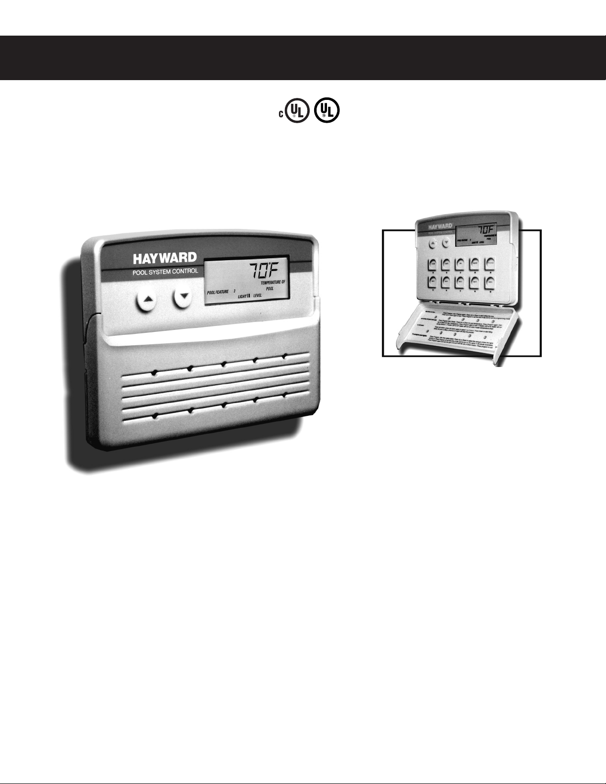
POOL SYSTEM CONTROL
INSTALLATION AND PROGRAMMING INSTRUCTIONS
SAVE THESE INSTRUCTIONS
ISPSC2100-2
LISTED
SWIMMING POOL AND
SPA CONTROL
3Z62
Designed and engineered for today’s carefree lifestyle. The 2100 Series sets
new standards of ease of operation and performance for remote pool system
control. The easy-to-install master remote control allows you to monitor, set
and control up to 12 functions necessary for total pool system control as well
as pool environment control.
Page 2

WATER SAFETY INSTRUCTIONS . . . . . . . . . . . . . . . . . . . . . . . . . . . . . . . . . . . . . . . . . . . . . . . . . . . .3
ELECTRICAL SPECIFICATIONS . . . . . . . . . . . . . . . . . . . . . . . . . . . . . . . . . . . . . . . . . . . . . . . . . . . . .3
ELECTRICAL SAFETY INSTRUCTIONS . . . . . . . . . . . . . . . . . . . . . . . . . . . . . . . . . . . . . . . . . . . . . . .4
INSTRUCTIONS FOR OPTIONAL RF CONTROLS . . . . . . . . . . . . . . . . . . . . . . . . . . . . . . . . . . . . . . .4
PRODUCT SPECIFICATIONS . . . . . . . . . . . . . . . . . . . . . . . . . . . . . . . . . . . . . . . . . . . . . . . . . . . . . . .5
APPLICATION OVERVIEW . . . . . . . . . . . . . . . . . . . . . . . . . . . . . . . . . . . . . . . . . . . . . . . . . . . . . . . . .6
SYSTEM OVERVIEW . . . . . . . . . . . . . . . . . . . . . . . . . . . . . . . . . . . . . . . . . . . . . . . . . . . . . . . . . . . . .7
OPTIONAL ACCESSORIES . . . . . . . . . . . . . . . . . . . . . . . . . . . . . . . . . . . . . . . . . . . . . . . . . . . . . . . . .8
PH/ORP OPTION . . . . . . . . . . . . . . . . . . . . . . . . . . . . . . . . . . . . . . . . . . . . . . . . . . . . . . . . . . . . . . . .9
TYPICAL PLUMBING SCHEMATIC . . . . . . . . . . . . . . . . . . . . . . . . . . . . . . . . . . . . . . . . . . . . . . . . . .11
INSTALLING THE WATER TEMPERATURE SENSOR . . . . . . . . . . . . . . . . . . . . . . . . . . . . . . . . . . . .21
INSTALLING THE AIR TEMPERATURE SENSOR. . . . . . . . . . . . . . . . . . . . . . . . . . . . . . . . . . . . . . .21
LOCATING & INSTALLING MAIN CONTROL CENTER . . . . . . . . . . . . . . . . . . . . . . . . . . . . . . . . . . .22
LOCATING & INSTALLING MASTER CONTROL PANEL . . . . . . . . . . . . . . . . . . . . . . . . . . . . . . . . . .24
TEMPLATE FOR MASTER CONTROL PANEL . . . . . . . . . . . . . . . . . . . . . . . . . . . . . . . . . . . . . . . . .25
INSTALLING OPTIONAL RF PANELS . . . . . . . . . . . . . . . . . . . . . . . . . . . . . . . . . . . . . . . . . . . . . . . .26
LOCATING & INSTALLING SPA SIDE CONTROL PANEL . . . . . . . . . . . . . . . . . . . . . . . . . . . . . . . . .29
CONNECTING LOW VOLTAGE COMPONENTS TO THE MAIN CONTROL CENTER . . . . . . . . . . . .33
CONNECTING HIGH VOLTAGE COMPONENTS TO THE MAIN CONTROL CENTER . . . . . . . . . . . .34
CONFIGURING THE SYSTEM . . . . . . . . . . . . . . . . . . . . . . . . . . . . . . . . . . . . . . . . . . . . . . . . . . . . .36
CONNECTING THE POWER SUPPLY . . . . . . . . . . . . . . . . . . . . . . . . . . . . . . . . . . . . . . . . . . . . . . .37
WIRELESS REMOTE OPERATION . . . . . . . . . . . . . . . . . . . . . . . . . . . . . . . . . . . . . . . . . . . . . . . . . .38
BUTTON FUNCTIONS FOR MAIN CONTROL CENTER. . . . . . . . . . . . . . . . . . . . . . . . . . . . . . . . . . .39
BUTTON FUNCTIONS FOR SPA SIDE CONTROL PANEL . . . . . . . . . . . . . . . . . . . . . . . . . . . . . . . .39
BUTTON FUNCTIONS FOR SERVICE PANEL . . . . . . . . . . . . . . . . . . . . . . . . . . . . . . . . . . . . . . . . .40
TROUBLE SHOOTING GUIDE . . . . . . . . . . . . . . . . . . . . . . . . . . . . . . . . . . . . . . . . . . . . . . . . . . . . .40
BASIC PROGRAMMING FOR MASTER CONTROL PANEL . . . . . . . . . . . . . . . . . . . . . . . . . . . . . . .41
2
TABLE OF CONTENTS
Page 3
STANDARD INPUTS:
Master Control Panel
Spa-Side Control Panel
Service Control Panel
Air Temperature Sensor
Water Temperature Sensor
3
IMPORTANT WATER SAFETY INSTRUCTIONS
When installing and using these Control Systems, basic safety precautions should always be followed,
including those listed below:
READ AND FOLLOW ALL INSTRUCTIONS
1. WARNING - Risk of Accidental Drowning. Extreme caution must be exercised to prevent unauthorized
access by children. To avoid accidents, ensure that children cannot use the spa or pool to which this Control
System is connected unless they are closely supervised at all times.
2. DANGER - To reduce the risk of drowning from hair or body entrapment, assure that the suction fittings,
skimmers and main drains in the spa or pool connected to this Control System are approved for the
application.
3. DANGER - To reduce the risk of injury, do not remove the suction fittings or main drain covers. Never operate
the spa or pool if these covers are broken or missing.
4. WARNING - To reduce the risk of injury:
A. The water in a spa to which the Control System is connected should never exceed 104°F (40°C). Water
temperatures between 100°F (38°C) and 104°F (40°C) are considered safe for a healthy adult. Lower
water temperatures are recommended for young children and when spa use exceeds 10 minutes.
B. Since excessive water temperatures have high potential for causing fetal damage during the early months
of pregnancy, pregnant or possibly pregnant women should limit spa water temperatures to 100°F (38°C).
C. Before entering a spa, the user should measure the water temperature with an accurate thermometer
since the tolerance of water temperature-regulating devices vary.
D. Prolonged immersion in water hotter than 104°F (40°C) may cause hyperthermia. Hyperthermia occurs
when the internal body temperature reaches a level several degrees above normal body temperature of
98.6°F (37°C). The symptoms of hyperthermia include dizziness, fainting, drowsiness, lethargy, and an
increase in the internal temperature of the body. The effects of hyperthermia include:
E. The use of alcohol, drugs, or medication can greatly increase the risk of fatal hyperthermia.
F. Leave the spa immediately if nausea, dizziness or headaches occur. Immediately cool the body by taking
a cool shower or by applying cold towels or ice packs. If the symptoms persist, seek medical attention.
G. The use of alcohol, drugs, or medication before or during spa use may lead to unconsciousness with the
possibility of drowning.
H. Obese persons and persons with a history of heart disease, low or high blood pressure, circulatory system
problems, or diabetes should consult a physician before using a spa.
I. Persons using medication should consult a physician before using a spa since some medication may
induce drowsiness or may affect heart rate, blood pressure, and circulation.
5. Occasional users of the spa should be made aware of these important Safety Instructions.
6. WARNING - People with infectious diseases should not use a spa or pool.
7. WARNING - To avoid injury, exercise care when entering and exiting a spa or pool.
8. WARNING - Do not use a spa immediately following strenuous exercise.
9. CAUTION - Maintain water chemistry to provide safe bathing environment.
SAVE THESE INSTRUCTIONS
1. Unawareness of impending hazard.
2. Failure to perceive heat.
3. Failure to recognize the need to exit
the spa.
4. Physical inability to exit the spa.
5. Fetal damage in pregnant women.
6. Unconsciousness resulting in a danger of
drowning.
ELECTRICAL SPECIFICATIONS
POWER SUPPLY:
BASIC 50A MAX.
SYSTEM:
-240 vac, 3 wire plus
ground, 20-50A max.
EXPANDER
CIRCUIT BOARDS:
-120 vac and/or 240
vac, 2 wire plus
ground
Power Supply must be
60Hz.
OPTIONAL INPUTS:
2nd Master Control Panel
pH Sensor
ORP Sensor
Solar Sensor (future)
R.F. Remote Control Panels
for Pool and Spa
OUTPUTS:
BASIC 20-50A MAX. SYSTEM
4 - Motorized Diverter Valves- 24 vac
1 - Gas Heater - 120/240 vac, max amperage 1.5A
1 - Filter Pump - 240 vac, max amperage 14.8A
1 - Cleaner Pump - 240 vac, max amperage 6.2A
1 - Spa Jet Pump - 240 vac, max amperage 11.8A
1 - Pool Lighting Option - 120 vac, max amperage 1.6A
1 - Underwater Lighting System- 120 vac, max
amperage 10.3A
1 - Aux. Lighting System - yard lights,120 vac, max
amperage 10.3A
1 - Fill Valve 24 vac, max amperage 0.3A
EXPANDER CIRCUIT BOARD:
2 - Auxiliary Circuits -120/240 vac, max amperage 16A
each circuit
Page 4
4
IMPORTANT ELECTRICAL SAFETY INSTRUCTIONS
When installing and using these Control Systems, basic safety precautions should always be followed, including
those listed below:
READ AND FOLLOW ALL INSTRUCTIONS
1. DANGER - Risk of electric shock. Before making any electrical connections, make certain that the Main Power
breaker from the house breaker box has been turned off.
2. DANGER - Risk of Electric Shock. Do not permit any electric appliance, such as a light, telephone, radio, or
television within 5' (1.5m) of a pool or spa.
3. All electrical work must be performed by a qualified electrician and must conform to all national, state, and local
codes.
4. Do not install or service this equipment if precipitation is present or imminent.
5. Install the Main Control Center in an area that is not prone to flooding.
6. Install the Main Control Center and all other high voltage components at least 5' (1.5m) from the inside wall of the
pool or spa. Canadian installations must be installed at least 3 meters from the inside wall of the pool or spa.
7. A terminal marked “GROUND” is provided within the Main Control Center enclosure. To reduce the risk of electrical
shock, connect this terminal to the grounding terminal of the electric supply panel with a continuous green insulated
copper wire equivalent in size to the circuit conductors supplying this equipment, but no smaller than #12 AWG.
8. A bonding wire connector is provided on the outside of the Main Control Center to accommodate the connection of
a min #8 AWG solid copper conductor (#6 AWG in Canada) between this unit and the local common bonding grid
in the spa and pool area. Additionally, any metal equipment, metal ladders, metal enclosure of electrical equipment,
metal water pipe, or conduit within 5' of the unit or within 5' of the pool (3 meters in Canada) must be connected to
the bonding wire connector.
9. The electrical supply circuit connected to the Main Control Center must be equipped with a suitably rated
disconnect device - a circuit breaker, a GFCI circuit breaker, switch or other device capable of opening all
ungrounded conductors in the supply circuit. This disconnect must be installed at least 5' from the pool or spa, but
be within sight of and readily accessible to the user.
10. This Control System is intended to supply the high voltage (120-240 vac) to a gas heater, and is intended to
override the thermostat in the control circuit of all the heaters. This Control System is intended to control gas
heaters that provide a safety circuit that include high temperature limit switch(s).
11. A suitably rated circuit breaker or a GFCI circuit breaker, must be installed in the electrical supply circuit connected
to the main control center. This circuit breaker may also provide the disconnect function referenced in item 9 if it
meets the sight and accessibility criteria.
12. This control system is provided with an Integral Ground-Fault Circuit Interrupter for the underwater lighting circuit. It
is located on the right side of the control enclosure under a Weather-Tite cover.
This GFCI must be tested before each use of the pool or spa. To test the GFCI, follow the following steps:
1. Turn on the underwater pool lighting circuit.
2. Press the ‘RESET’ button fully.
3. Check the underwater lights to be sure they are illuminated.
4. Press the ‘TEST’ button in order to trip the GFCI. The ‘RESET’ button will pop out and the underwater lights
will go out.
5. Press the ‘RESET’ again and the underwater lights will again be illuminated.
If this GFCI fails to operate in this manner there is a ground current flowing indicating the possibility of an
electric shock. Disconnect the power until the fault has been identified and corrected.
SAVE THESE INSTRUCTIONS
INSTRUCTIONS FOR OPTIONAL RF CONTROLS
Units which include the optional RF Antenna, RF Master Control, and RF Infrared Control shall include these
additional instructions:
1. RF Antenna and RF Master Control shall be installed at least 5 feet from the inside wall of a pool or spa.
2. The RF Antenna, RF Master Control, and the RF Infrared Remote are optional accessories for use with
Listed Controls, Models PC-XXXXXX-DCA and BPC-XXXXXX-DCA.
3. The RF Antenna and the RF Master Control must be installed in accordance to NEC regulations.
Page 5
5
PRODUCT SPECIFICATIONS
POOL/SPA CONTROL - PSC2104
ITEMS INCLUDED
PSC2002 MAIN CONTROL CENTER WITH KNOCKOUTS
PSC2001 MASTER CONTROL PANEL
PSC2023 AIR TEMPERATURE SENSOR
PSC2022 WATER TEMPERATURE SENSOR
PSC2005 SPA SIDE CONTROL WITH 100’ OF CABLE INCL.
VALVE ACTUATORS (2 SUPPLIED)
POOL CONTROL - PSC2105
ITEMS INCLUDED
PSC2002 MAIN CONTROL CENTER WITH KNOCKOUTS
PSC2001 MASTER CONTROL PANEL
PSC2023 AIR TEMPERATURE SENSOR
PSC2022 WATER TEMPERATURE SENSOR
OPTION
PSC 2003 SPA SIDE CONTROL WITH 100’ CABLE INCLUDED.
LOW VOLTAGE
COMPARTMENT
KNOCKOUTS
(2) 1/2” KNOCKOUTS
LEFT SIDE
(2) 1/2” KNOCKOUTS
RIGHT SIDE
SPA SIDE CONTROL PANEL
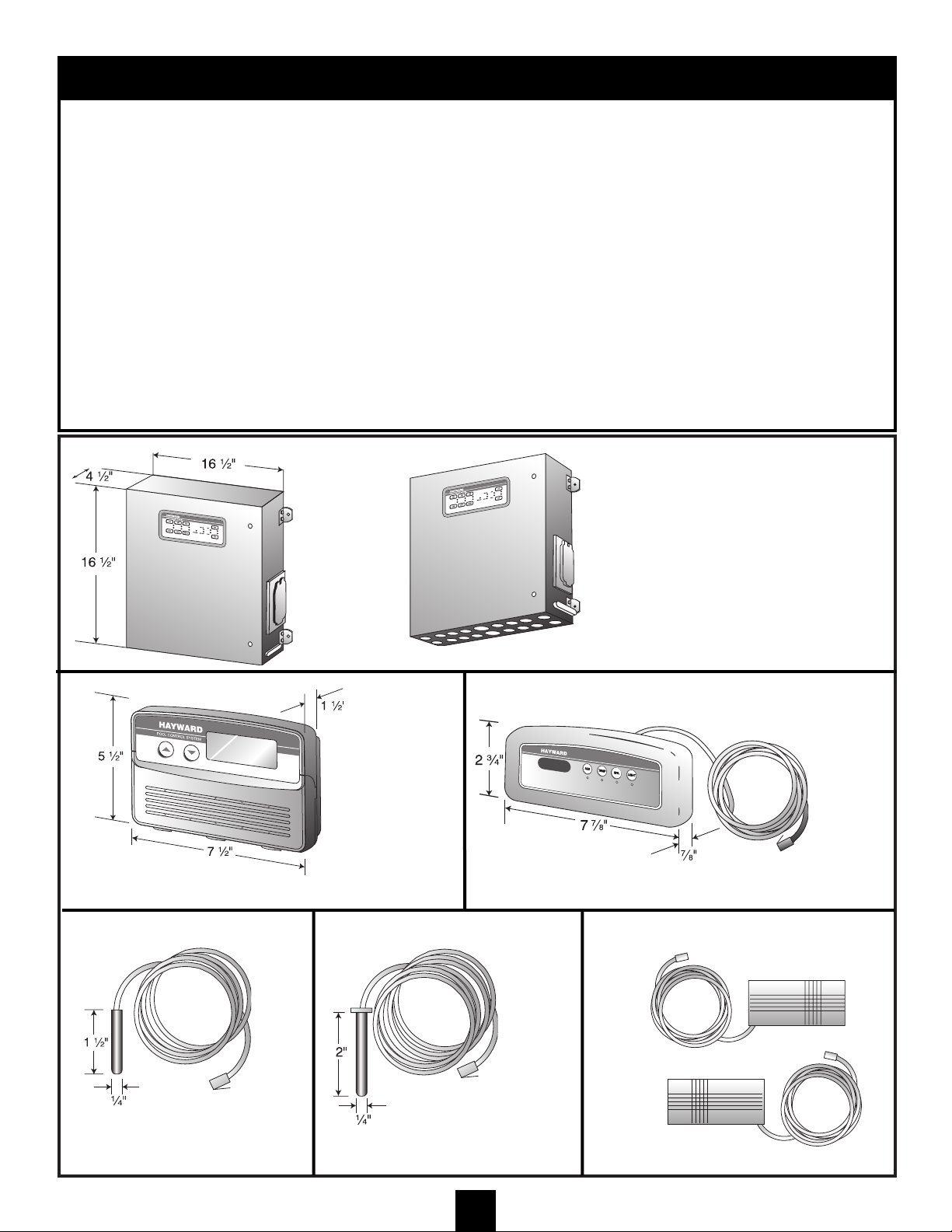
MAIN
CONTROL
CENTER
WIDTH-16 1/2”
HEIGHT-16 1/2”
DEPTH-4 1/2”
MASTER
CONTROL
PANEL
WIDTH-7 1/2”
HEIGHT-5 1/2”
DEPTH-1 1/2”
WIDTH-5 7/8”
HEIGHT-2 3/4”
DEPTH-7/8”
PSC2003 100’ or 200’ OF CABLE (SPECIFY)
CABLE LENGTH AVAILABLE
50’, 100’, 200’ (NOT INCLUDED)
DIAMETER-1/4”
LENGTH-1 1/2”
10’ OF CABLE INCLUDED
DIAMETER-1/4”
LENGTH-2”
25’ OF CABLE INCLUDED
POWER CABLE LENGTH- 10’
AIR TEMPERATURE SENSOR WATER TEMPERATURE SENSOR VALVE ACTUATORS
(MODEL 2100 ONLY)
ITEM #-PSC2002
ITEM #-PSC2023 ITEM #-PSC2022
ITEM #-PSC2001
HIGH VOLTAGE
COMPARTMENT
KNOCKOUTS
(6) 1/2” KNOCKOUTS
LEFT SIDE
(7) 3/4” KNOCKOUTS
RIGHT SIDE
(1) 1” KNOCKOUTS
CONDUIT KNOCKOUTS
POOL/SPA CONTROL W/WIRELESS REMOTE
- PSC2106
ITEMS INCLUDED
PSC2002 MAIN CONTROL CENTER WITH KNOCKOUTS
PSC2001 MASTER CONTROL PANEL
PSC2023 AIR TEMPERATURE SENSOR
PSC2022 WATER TEMPERATURE SENSOR
PSC2108 RF WIRELESS SPA REMOTE UPGRADE KIT
VALVE ACTUATORS (2 SUPPLIED)
POOL CONTROL W/WIRELESS REMOTE & WIRELESS
MASTER PANEL
- PSC2109
ITEMS INCLUDED
PSC2002 MAIN CONTROL CENTER WITH KNOCKOUTS
PSC2001 MASTER CONTROL PANEL
PSC2023 AIR TEMPERATURE SENSOR
PSC2022 WATER TEMPERATURE SENSOR
PSC2108 RF WIRELESS SPA REMOTE UPGRADE KIT
PSC2107 RF WIRELESS MASTER PANEL UPGRADE KIT
VALVE ACTUATORS (2 SUPPLIED)
ITEM #-PSA24
Page 6
SOLAR
Notes:
Additional local disconnect
may be required if main
breakers DO NOT meet the
requirements of a local
disconnect.
See IMPORTANT
ELECTRICAL SAFETY
INSTRUCTIONS
Maximum Amp draw for
basic 50 Amp system is
40 Amps.
Cleaner Pump disabled
when Jet Pump is on.
Jet Pump disabled when
Cleaner Pump is on.
6
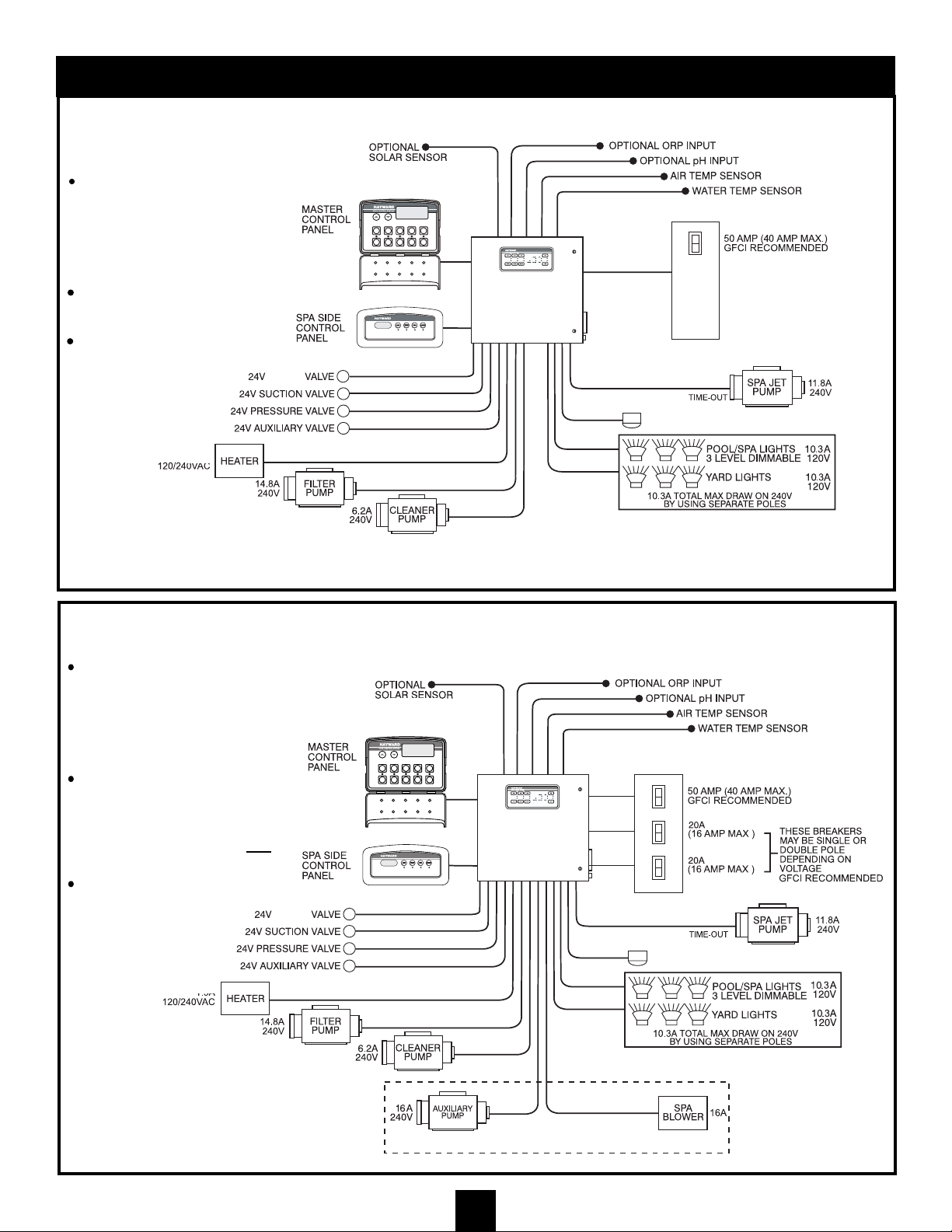
APPLICATION OVERVIEW
SOLAR
BASIC 20-50 AMP MAX SYSTEM (Without Expander Board Use)
BASIC SYSTEM WITH 20A X 20A (MAX) EXPANDER CIRCUIT BOARD
Notes:
Additional local disconnect
may be required if main
breakers DO NOT meet the
requirements of a local
disconnect.
See IMPORTANT
ELECTRICAL SAFETY
INSTRUCTIONS
Max Amp draw for the Basic
50 Amp System and
Expander Board
Basic 50 Amp System- 40A
Expander Board Circuit #1- 16A
Expander Board Circuit #2- 16A
Total 72A
Cleaner Pump disabled
when Jet Pump is on.
Jet Pump disabled when
Cleaner Pump is on.
20 X 20 EXPANDER BOARD
MAIN POWER PANEL
MAIN POWER PANEL
TWO HOUR
LIGHTING OPTION 1.6A
LIGHTING OPTION 1.6A
TWO HOUR
(future)
may be
2-speed
may be
2-speed
may be
2-speed
may be
2-speed
(future)
1.5A
1.5A
Page 7
50’, 100’, 200’
PANEL CONNECTING
CABLES OPTIONAL
7
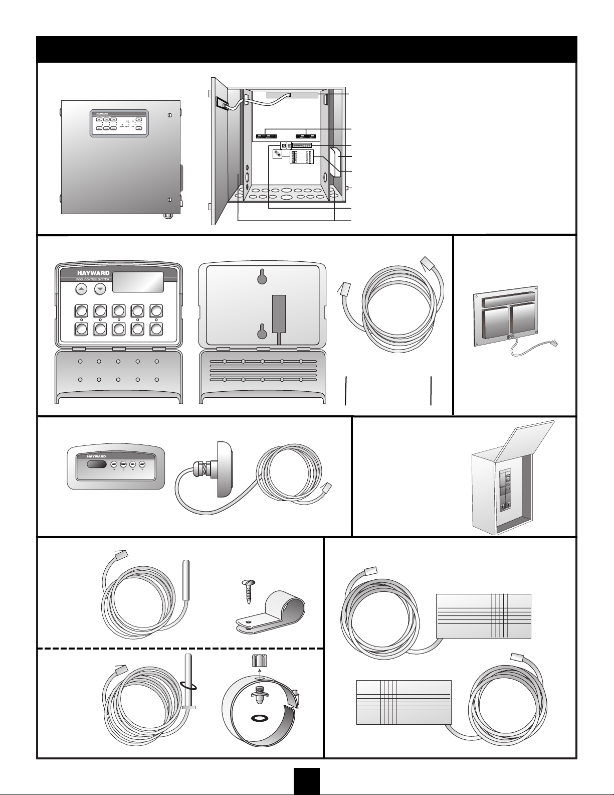
SYSTEM OVERVIEW
MAIN CONTROL CENTER
MASTER CONTROL PANEL
SPA SIDE CONTROL PANEL
INPUT SENSORS VALVE ACTUATORS
AIR TEMP
SENSOR
LOW VOLTAGE CONNECTIONS
EQUIPMENT OUTPUT CONNECTIONS
LINE NEUTRAL LUG NEUTRAL FOR 120V EQUIPMENT
BONDING LUGS FOR EQUIPMENT
WATER
TEMP
SENSOR
25’ CABLE
TWO SUPPLIED WITH POOL/SPA SERIES
SENSOR
MOUNT
MASTER CONTROL CABLE
Spa-side panels are available
on certain systems and have
100’ or 200’ cables.
GROUND LUGS
LOW VOLTAGE RACEWAYS
POWER INPUT LUGS
GFCI
10’ CABLE10’ CABLE
PSC2038
MOUNTING
CLIP
INTEGRATED
40 AMP
EXPANDER BOARD
-Can be wired for 120 VAC or
240 VAC, 2 wire plus ground
-Can be wired for 120 VAC and
240 VAC, 2 wire plus ground
ITEM #-PSC2004
CIRCUIT BREAKER
WITH ENCLOSURE
50 A MAX. GFCI
ITEM #-PSC2021
Page 8
8
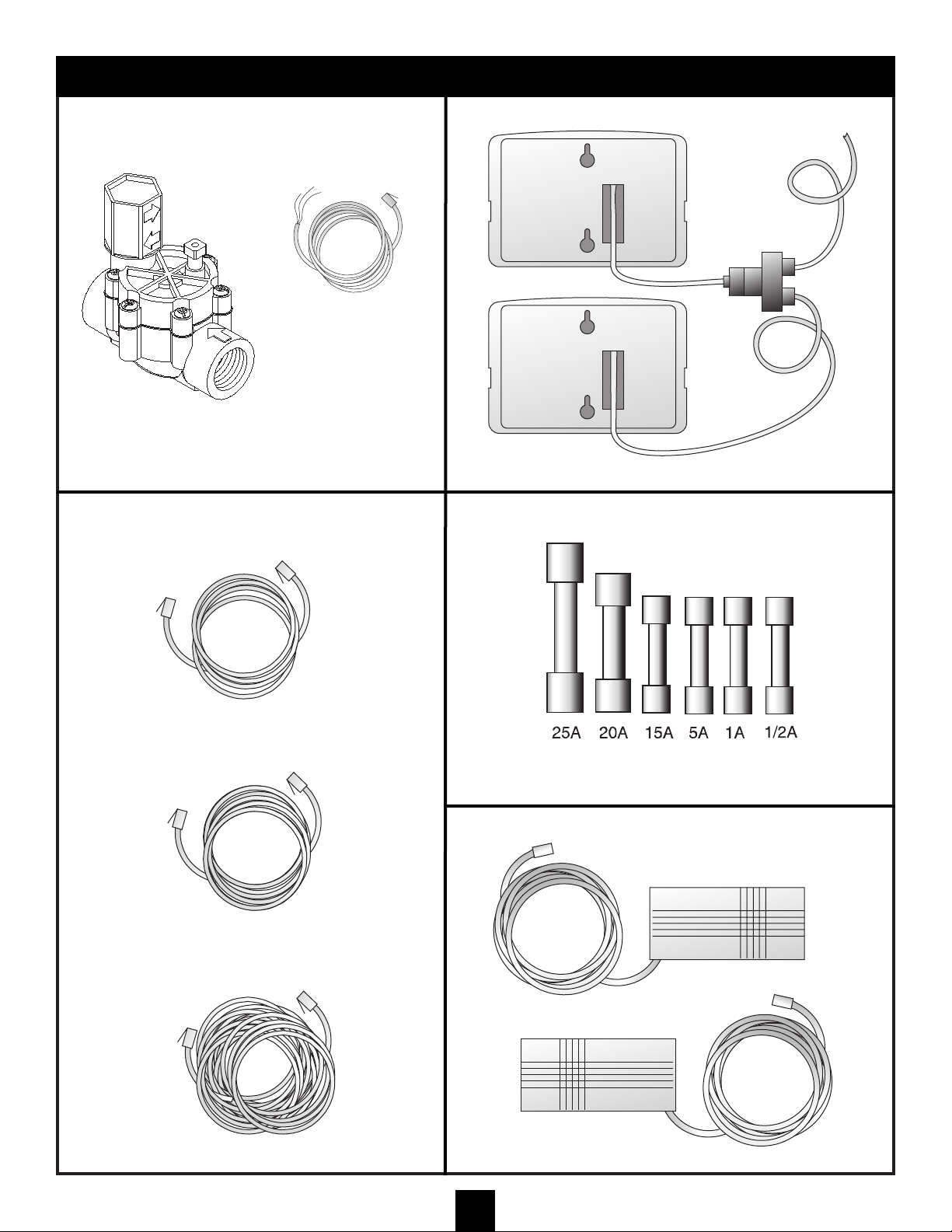
OPTIONAL ACCESSORIES
MASTER CONTROL PANEL
EXTENSION CABLES
2-1 CABLE
CONNECTOR
OPTIONAL FILL VALVE KIT
W/CONNECTOR CABLE
25’
50’
100’
200’
MASTER
CONTROL
PANEL
AUXILIARY
MASTER
PANEL
OPTIONAL ACTUATORS
ITEM #-PSC2020
ITEM #-PSC2014
ITEM#-PS2025
ITEM #-PSC2012
ITEM #-PSC2013
SPARE FUSES
Fuses are sized for maximum permissible output on each load circuit, in
certain applications it may be necessary to install lower rated fuses to comply
with the National Electrical Code.
ITEM#-PSA24
ITEM#-PS2036
Page 9

9
PH/ORP OPTION
CALIBRATION
CALIBRATION PROCEDURE
1. Test the pool water with a test kit (pH 7.2-7.8; Orp 500-750mV)
2. If the ph/Orp sensors readings are not correct, use a small flat head screwdriver to adjust the potentiometer
(R11) on the pH circuit board. Very slowly adjust the potentiometer until the display on the panel shows the
correct reading.
Note: Wait until the display reads a constant correct setting before moving to next step.
3. Calibration is completed.
4. The display on the panel will show the actual pH reading in the spa. Add any necessary chemicals to insure that
the pH sensor reading remains between 7.2 and 7.8 pH.
5. Requirement: Use a test kit no less than once a month to verify calibration and optimal Orp reading.
Note: ORP readings are affected by the following factors: water temperature, total dissolved solids,
cyanuric acid, and alkalinity.
INSTALLATION
1. Splice in a 1 1/2" x 1 1/2" x 1/2" or 2" x 2" x 1/2" reducer tee (depending upon size of pipe configuration).
Position the 1/2” female pipe thread on the tee at approximately 45°.
2. Press the two stand-offs into the digital control board.
3. Remove the pH jumper from the 4-pin connector (J20 for circuit board #25500 or J11 for circuit board #25501) on
the control board.
4. Install the pH board onto the control board. Important! The pH board must be installed component side up.
Make sure that J20 or J11 and the two stand-offs snap fit into the pH board.
Note: All sensors are shipped with the measuring end covered with a wetting cap.
5. Remove the wetting cap by twisting it counter-clockwise and gently easing it off. It is recommended that this cap
be retained for future long-term storage and winterization.
Note: Hand tighten sensors in place. Do not use a wrench to install the sensor as this could cause breakage.
Use a wrench to remove the sensor only if unable to do so by hand.
6. Install the pH sensor into the 1/2" NPT tee by turning the sensor clockwise. Hand tighten only.
7. Feed the BNC connector (from the outside of the control box) through a hole on the bottom LEFT side of the box
for a horizontally-mounted system. Pass the BNC connector through a hole on the bottom RIGHT side of the
control box for a vertically-mounted system.
8. Connect the BNC connector to the pH board. First align it with its mated connector, then press them together
and then twist to lock them into place.
9. Turn the system power on.
CARE AND MAINTENANCE
UNPACKING
Remove the electrode from its package and check that it is undamaged. If damaged, contact your supplier for
replacement. Most electrodes are rugged in design, but some are fragile. Care should be taken when unpacking
and handling all electrodes.
PREPARATIONS FOR USE
All electrodes are shipped with a wetting cap covering the measuring end. This cap contains a solution of pH 4
buffer saturated with potassium chloride for single-junction combination electrodes, and solution of potassium nitrate
in pH 4 buffer for double-junction electrodes. Mono-measuring electrodes, pH and ORP, are shipped in pH 4 buffer.
Page 10

Gently remove the wetting cap from the electrode by unscrewing the bottle form the cap and then sliding the cap
and o-ring off of the electrode body. Save the cap for future long-term storage. Some electrodes are shipped with
slide-on caps sealed with teflon tape, these caps are simply pulled off.
During shipping, the air space inside the pH glass internal may have moved into the bulb. Grasp the electrode near
the cable end and gently swing it through an arc to force the internal electrolyte into the pH bulb.
ELECTRODE CLEANING
Slow response and large offsets may indicate the electrode has become coated. The nature of the coating will
dictate the type of cleaning technique that should be used.
Soft coatings, like foodstuffs or bacterial films are best removed using a squirt bottle or the water jet from a faucet. If
this is not successful, then wiping with a soft, wet cloth is the best choice.
Hard coatings, like calcium or lime scale are best removed with a solvent appropriate for the particular coating. A
5% solution of HCI would be a good choice for the calcium scale. If unsure of the proper solvent to remove a hard
mineral coating, alternate between a 5% HCI and a 4% NaOH for 10 minutes each. After treating the electrode with
these strong acids or bases, rinse the electrode with water and soak it in pH 4 buffer for at least 1/2 hour.
Greasy and oil coatings are best removed with a detergent solution or a solvent that will not attack the electrodes
body. Methanol and isopropyl alcohol are good choices for solvents. Acetone, MEK, THF, or trichloroethane will
irreparably harm the electrode. A soft toothbrush can be used with the detergent in removing stubborn coatings.
The platinum or gold sensing tip of an ORP electrode should be cleaned just like a pH electrode. The surface can
also be cleaned with an abrasive as a last resort. Gently scour the platinum with a 600 grit wet emery cloth or
preferably a 1-3 micron alumina polishing powder.
Important: Good laboratory practices should be used and protective gloves and safety glasses should be worn while
handling any solvents or chemicals. If you are unsure of the proper technique for handling a chemical or of its
hazardous properties, it is best to discard the electrode, eliminating the risk of danger.
INTERPRETING PH/ORP READINGS
1. To check the measured pH and/or ORP readings, run the filter pump for at least 5 minutes. Press the DOWN
arrow button on the master panel until the desired reading is displayed. The DOWN button will toggle the display
through the available chemical sensor readings.
2. Adjust water chemistry as close to these suggested readings as possible:
Alkalinity: 100 ppm
Total Dissolved Solids (TDS): 500 ppm
PH: 7.2 - 7.8
3. Once water chemistry has been adjusted as per #1, note ORP reading (mV). This reading can be used to
indicate proper water chemistry in your installation. If the ORP reading changes dramatically, adjust the water
chemistry accordingly.
4. Millivolt reading should fall between 500-750 mV.
5. If ORP reading falls outside of suggested range, adjust water chemistry accordingly.
Note: ORP readings are affected by the following factors: water temperature, total dissolved solids,
cyanuric acid, and alkalinity.
WINTERIZATION
1. Disconnect the sensor connector from the PCB board located in the power center.
2. Carefully remove the sensors from the plumbing.
3. Reinsert the electrode into the wetting cap and fill cap with pool water.
4. Store at room temperature.
5. When reinstalling the probe, refer back to the Preparation for Use section of the Care and Maintenance
instructions.
10
PH/ORP OPTION (continued)
Page 11
11
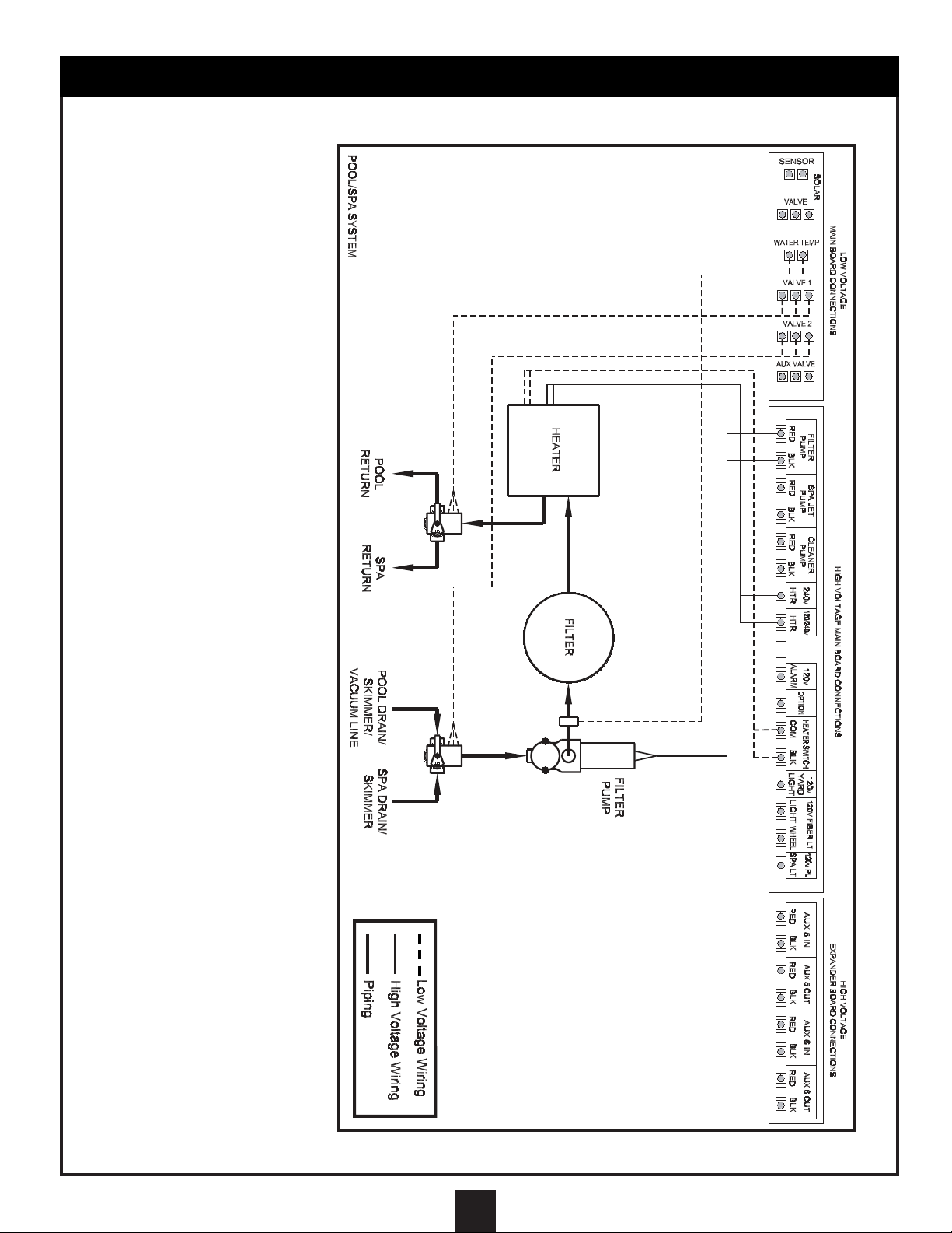
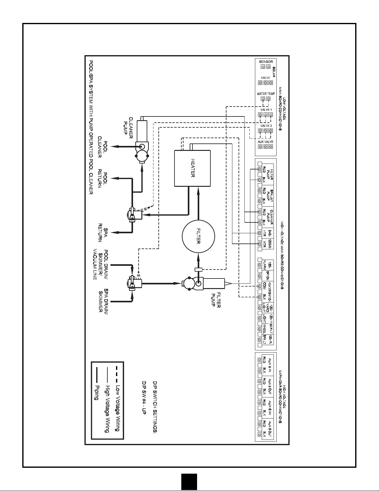
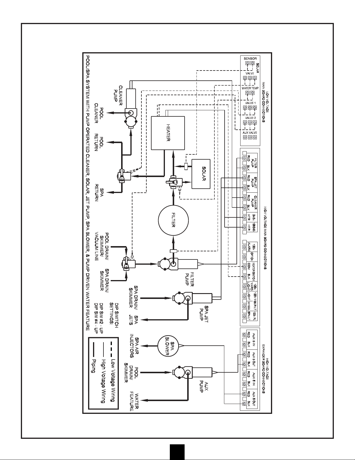
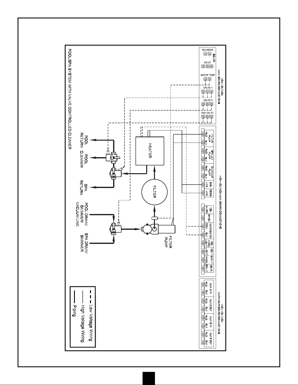
TYPICAL PLUMBING SCHEMATIC
1. Reverse the polarity of
the wiring to the valve
diverter motor that is out
of synchronization. The
best way to accomplish
this is to reverse the red
and white wires inside
the valve diverter motor
enclosure.
2. Remove the motor
enclosure cover, remove
the wire nuts, switch
the red and white wires,
reconnect the wires
with wire nuts, and
reinstall cover.
BASIC POOL/SPA PLUMBING:
These schematics show the
necessary plumbing required
to operate a pool and a spa
that share common pumps,
filters, and heaters. The
Motorized Diverter Valves
will change position when spa
use is desired.
IMPORTANT:
Be sure the valves are
synchronized to move
simultaneously from pool
suction and pool return to
the spa suction and spa
return. If they are not
synchronized, please follow
the instructions below:
NOTE:
The polarity of the wiring to
the valve motor that is out of
synchronization can also be
reversed by changing the
position of the toggle switch
to the reverse position.
If you select this method to
reverse polarity, be sure to
change the sticker at the rear
of the motor enclosure from
the black (Auto-Off-Reverse)
sticker to the white (ReverseOff- Auto) sticker.
You must change the sticker
so that users and service
personnel know the correct
auto position for the valve.
Page 12
12
TYPICAL PLUMBING SCHEMATIC (continued)
Page 13
TYPICAL PLUMBING SCHEMATIC (continued)
13
Page 14
TYPICAL PLUMBING SCHEMATIC (continued)
14
Page 15

TYPICAL PLUMBING SCHEMATIC (continued)
15
Page 16

TYPICAL PLUMBING SCHEMATIC (continued)
16
Page 17

TYPICAL PLUMBING SCHEMATIC (continued)
17
Page 18

TYPICAL PLUMBING SCHEMATIC (continued)
18
Page 19

TYPICAL PLUMBING SCHEMATIC (continued)
19
Page 20

TYPICAL PLUMBING SCHEMATIC (continued)
20
Page 21

21
INSTALLING TEMPERATURE SENSORS
ATTENTION: The air temperature sensor is 10’ long and the water
temperature sensor is 25’ long. Consider the sensor mounting locations
BEFORE mounting the Main Control Center.
TO INSTALL THE WATER TEMPERATURE SENSOR
1. ATTENTION: Before connecting the temperature sensor wire to the
Main Control Center circuit board, the sensor wire must be inserted
through the sensor retaining nut. Insert the sensor wire through the
nut and slide the nut to a position adjacent to the sensing bulb.
2. Locate the Water Temperature Sensor in the discharge (pressure)
line of the filter pump as shown in the Basic Plumbing Schematic.
Drill a .390" (25/64") hole in the pipe and install the sensor mount
on the pipe by tightening the sensor mount clamp.
3. Install the O-ring onto the water temperature sensor. Slide the Oring onto the water temperature sensor so that it is positioned
against the plastic flange on the water temperature sensor. With
the retaining nut and O-ring installed on the water temperature
sensor, insert the water temperature sensor into the sensor mount
and tighten the nut, hand tight only. DO NOT OVER TIGHTEN.
FREEZE PROTECTION FEATURE
ONLY ACTIVE WHEN VALVES ARE IN POOL MODE
When the system senses air temperature of 35°F or lower, the valves
will turn to Pool and the filter pump, Aux 1, Aux 3, and Aux 5 will turn
on for 30 minutes. After 30 minutes, these devices will turn off, and the
valves will turn to Spa. At that time the Spa Aux, Filter Pump and
Blower will run for 30 minutes. After 30 minutes the system will again
turn off and the valves will turn to Pool again. The cycle will repeat if
the system still senses air temperature of 35°F or lower.
Note: This feature is designed to protect the pool equipment in
the event of unforeseen or unseasonal freezing conditions. It is
not intended to take the place of proper winterizing procedures.
Freeze protection disabled in Spa Mode.
TO INSTALL THE AIR TEMPERATURE SENSOR
OUTSIDE BUILDING LOCATION OPTION
1. Locate the Air Temperature Sensor so that it will be exposed to the
outside ambient temperature.
2. If the Main Control Center is installed inside a building and is
adjacent to heat generating devices such as heaters and pumps,
route the Air Temperature Sensor Cable through the wall of the
building securing the cable neatly and then secure the Air
Temperature Sensor with the clip and screw provided. Avoid
attaching the Air Temperature Sensor to any surface that will get
hotter than the ambient air temperature.
MAIN CONTROL CENTER LOCATION OPTION
3. If the Main Control Center is not installed in a building and there is
no benefit to installing the air sensor remotely, position the sensor
in a Liquid-Tite connector installed in one of the knock outs
beneath the low voltage raceways as shown in illustration.
RETAINING NUT
WATER TEMPERATURE
SENSOR
O-RING
SENSOR
FITTING
WASHER
PUMP
DISCHARGE
LINE
.390” HOLE
SENSOR
MOUNT
CLAMP
OUTSIDE BUILDING
LOCATION OPTION
MAIN CONTROL CENTER LOCATION
MOUNT OPTION
AIR
TEMPERATURE
SENSOR
WATER TEMPERATURE
SENSOR LINE
LOW VOLTAGE
KNOCK OUTS IN MAIN
CONTROL CENTER
Page 22

The Main Control Center should be located as close as possible to the pumps, heater, valves, and sensors that are
required to be connected to it. Preferably, the system should mount inside a pool equipment house or other
enclosure. However, the system can be mounted outside. It should mount on a flat vertical wall and be positioned
so that the conduit knockouts are located at the bottom of the enclosure. Remember to consider the length of the
wires & valve wires when selecting the final location.
ATTENTION: POSITIONING THE ENCLOSURE WITH THE CONDUIT KNOCKOUTS
LOCATED AT THE SIDE OR THE TOP OF THE ENCLOSURE MAY ALLOW WATER TO
ENTER THE SYSTEM AND CAUSE DAMAGE TO THE SYSTEM AND/OR CREATE AN
ELECTRICAL SHOCK HAZARD.
Be sure that the system and all other electrical components are at least 5' from the edge of the pool or spa. When
selecting the mounting position, plan how the 1" rigid PVC conduit carrying the power to the Main Control Center
will be routed. Also plan for the routing of the flexible conduit that will be run to the pumps and heater. You should
also keep in mind that the cable length on the Air Temperature Sensor is 10’ long and the Water Temperature
Sensor is 25’ long. They must reach connector receptacles located inside the system. Additionally, the location
selected should provide clear access in front of the system to permit the owner or service personnel to stand in
front of the Main Control Center unobstructed by other equipment.
ATTENTION: BE SURE THE LOCATION CHOSEN FOR THE MAIN CONTROL CENTER
ALLOWS UNOBSTRUCTED ACCESS TO THE GFCI PROTECTING THE UNDERWATER
LIGHT CIRCUIT.
INSTALLATION:
After the location has been selected follow these easy steps to mount the Main Control Center:
1. If the mounting substrate will allow, mount the Main Control
Center by driving mounting screws through the holes
provided in the back of the enclosure and into the wall. If
wall anchors must be used, hold the Main Control Center
enclosure in position and mark the hole pattern on the wall.
Drill and set the anchors; fasten the enclosure with screws.
Be sure to position the Main Control Center level and
square for a neat installation.
2. Run electrical PVC conduit from the Power Supply Panel to
the Main Control Center. Determine the number of conduit
runs and the size of the conduit needed for the installation
based on the wire size being run, the number of conductors
within the conduit, and the number of circuits needed.
Typically, if the Main Power Panel is 100' or less from the
Main Control Center the 50A max. breaker will require
4- #6 AWG conductors, one each of red, black, white and
green. These conductors will require a 1" conduit run.
(The enclosure has been provided with 1" conduit
knockouts that are adjacent to the line terminals in the
Main Control Center.)
A. If the installation requires the use of additional circuits or an Expander Circuit Board is being used, you may elect to
run separate conduit runs for each expander circuit, or you may elect to run the expander circuit in a common
conduit, or you may elect to run it inside the 1" conduit with the 50A max. circuit. If the runs are 100' or less in
length the expander circuit board will require 3- #12 AWG conductors. If the loads on this circuit are 240 vac, the
colors of the conductors should be red, black and green. If the loads on this circuit are 120 vac, the colors should
be black, white, and green. These wires can be run in 1/2" or 3/4" conduit. Be sure to follow all codes in effect
regarding the number and size of conductors that can be installed in various sizes of conduit.
22
LOCATING AND INSTALLING THE MAIN CONTROL CENTER
Amperage to Maximum Breaker Copper Wire
Wire Gauge Ratios System Loads Rating Gauge
40A System 40A 50A 6 AWG
32A System 32A 40A 8AWG
24A System 24A 30A 10AWG
Page 23

23
LOCATING AND INSTALLING THE MAIN CONTROL CENTER (continued)
LOW VOLTAGE
(AUX, BOARD CONTROL
PH, ORP SENSORS)
CONTROL PANELS
ETC..
LOW VOLTAGE
AIR & WATER
TEMPERATURE SENSORS,
MOTORIZED
DIVERTER VALVES ETC..
POWER
INPUT
HIGH
VOLTAGE
OUTPUT
WIRING DIAGRAM
HIGH
VOLTAGE
OUTPUT
B. GFCI RECOMMENDATIONS
A Ground Fault Circuit Interrupter (GFCI) is recommended to be
installed in the electrical supply circuit connected to these products.
GFCI’s are ultrasensitive switching devices, providing the ultimate in
safety. The most common style of GFCI also provides high-current
protection as a circuit breaker, and may be required by code in
certain installations. Breaker must be sized in accordance with
applicable code.
A 50A max GFCI circuit breaker is the best method to obtain complete
system protection. An additional enclosure containing the 50A max
GFCI may need to be installed between the main power supply
(50A max breaker) and the pool control. This must be done in cases
where a 50A max GFCI circuit breaker cannot be found to fit the
existing electrical service. Additionally, it can meet the requirements of
a local disconnect if it is located properly.
SEE IMPORTANT ELECTRICAL SAFETY INSTRUCTIONS. PAGE 3
C. The Expander Circuit Board will require separate circuits for each relay
and consequently 2- 20A circuit breakers, single pole for 120V or
double pole for 240V. For a 120 vac circuit, use 3- #12 AWG
conductors; one each of black, white, and green. For a 240 vac circuit,
use 3- #12 AWG conductors; one each of red, black, and green. These
wires can be run in 1/2" or 3/4" conduit. The enclosure has been
provided with 1/2" or 3/4", and 1" conduit knockouts that are adjacent to
the line terminals in the Main Control Center.
D. If the conduit run is long or has numerous bends, use watertight pulling
fittings positioned in the middle of the run. If this is necessary, it is
advisable to elevate the pulling fitting at least 6" above finished grade of
the surrounding area to avoid potential flooding. Remember to complete
the installation of the conduit before concrete is poured that might
obstruct a direct route from the Power Supply Panel to the Main Control
Center. Be sure that underground conduit is positioned in well
compacted soil. Also use care when making the glue joint to be sure
they are watertight.
3. Pull the required conductors as outlined in #2 above and
connect the power supply conductors to the line terminals of the
Main Control Center, and if required to the line terminals at the
Expander Circuit Board.
4. DO NOT HOOK UP THE CONDUCTORS TO THE POWER
SUPPLY PANEL UNTIL ALL ELECTRICAL CONNECTIONS FOR
ALL LOADS (MOTORIZED VALVES, HEATER, PUMPS, LIGHTS,
ETC.) HAVE BEEN COMPLETED. This will assure that all conductors
are not energized while completing the installation.
NOTE: All of the electrical wiring methods and materials used to complete
the electrical installation of the Pool/Spa Control System must be
in accordance with the National Electrical Code or the Canadian
Electric Code, as well as any local electrical codes in effect at the
time of installation.
The selection of electrical materials required to accomplish this
installation and the installation of the Hayward Pool Control System
must be accomplished by, or be under the direct supervision of a
qualified electrician.
TO LINE NEUTRAL
CONNECTION OR
NEUTRAL BAR
INPUT/OUTPUT
LOAD NEUTRAL
TERMINAL TO
POWER SYSTEM
EXPANDER BOARD
STAND-OFFS IN MAIN
CONTROL CENTER
Page 24

24
LOCATING AND INSTALLING THE MASTER CONTROL PANEL
For maximum convenience the Master Control Panel should be installed inside the home of the user.
However, it can be installed outside if desired. It must be mounted on a vertical surface such as a wall and be
located at eye level for the user. While choosing the location, plan for the routing of the control cable from the
Main Control Center to the Master Control Panel.
TO INSTALL:
1. If the pool and spa equipment room housing the Main Control Center is attached to the main dwelling where
the Master Panel will be located, simply route the cable through attics and hollow walls securing the cable as
needed for a neat installation. Store excess cable in the attic or between walls.
2. If the pool and spa equipment room housing the Main Control Center is in a separate building from the main
dwelling where the Master Control Panel will be located, 1/2" or 3/4" conduit should be installed from the Main
Control Center conduit knockouts entering the low voltage compartment and extend at the other end of the
conduit to a point within the main dwelling. Route the cable through the conduit, and through attics and hollow
walls, securing the cable as needed for a neat installation. Store excess cable in the attic or between walls.
3. Next, drill a hole in the hollow wall at a location that will permit the cable to extend through the wall directly
behind the Master Panel. Pull the cable through the hole storing any excess cable in the attic or inside the
hollow wall. Install hollow wall anchors as needed on the Master Control Panel vertical centerline and 3" apart.
Install pan head screws into the anchors and adjust them so that the Master Control Panel rests snugly
against the wall when it is installed on the screws. Plug the control cable into the receptacle at the rear of the
panel and install on the wall anchor screws.
4. If the Master Control Panel is mounted outside, be sure to route the control cable so that it approaches the
panel from the bottom and enters below the panel vertically. Secure the cable to the wall to maintain this cable
orientation. This will prevent water from running down the cable connectors and into the Master Control Panel.
5. An Additional Master Control Panel can be added to the system by connecting a 2-1 cable connector to the
end of the cable coming from the Main Control Center. This provides 2 outputs for 2 Master Control Panels.
Connector cables are then run between the 2-1 cable connector and the Master Control Panels. The additional
Master Control Panels will perform the same functions and all panels will indicate system status
simultaneously. Master Control Panels and connecting cables are available as an option.
ATTENTION: IF A CABLE IS NOT LONG ENOUGH TO REACH FROM THE MASTER PANEL TO THE
MAIN CONTROL CENTER, DO NOT ADD LENGTH TO THE CABLE BY SPLICING ADDITIONAL CABLE
ONTO THE CABLE; OBTAIN A CABLE THAT IS LONG ENOUGH TO REACH. A CABLE THAT IS TOO
LONG MAY BE SHORTENED BY CUTTING OFF THE EXCESS AND REINSTALLING A NEW
CONNECTOR AT THE DESIRED LENGTH.
SEE TEMPLATE ON PAGE 17
CONTROL CABLE
PLUGS IN HERE
HOLLOW WALL ANCHORS
PANEL
POSITION
CONTROL
CABLE
KEY SLOTS
FOR HANGING
3”
Page 25

LOCATING AND INSTALLING THE MASTER CONTROL PANEL (continued)
USE THIS FULL SIZED TEMPLATE FOR
CORRECT POSITIONING OF MASTER
CONTROL PANEL ON WALL
25
3”
Page 26

INSTALLING OPTIONAL RF PANELS
26
Under ideal conditions, the Hayward RF Spa Remote Kit allows a user to position the spa remote controller
anywhere within 100 ft. of the Main Control Center without a hard-wired connection. The range for an
improperly installed unit can be as low as 25 ft.
Certain physical or architectural structures may interfere with the performance of the unit, so
care must be given to the installation (See instructions on page 27). While a hard-wired
Master Panel can be installed outdoors, the RF Master Panel is not suitable for outdoor
installation and should be stored indoors when not in use.
WARNING: ALL POWER MUST BE SHUT OFF
BEFORE INSTALLATION. DO NOT ATTEMPT TO
WORK INSIDE THE HAYWARD POOL SYSTEM
CONTROL WITH ANY LIVE ELECTRICAL PARTS.
Begin the installation by turning off the main
power (50 Amp Max) to the Hayward Pool
System Control at the house breaker box.
If there is an expander board installed
(Aux 5 and/or spa blower), turn off the
power to the two individual circuits
(20 Amp Max each) that may be
installed to the expander board.
INST
ALL HAYWARD RF MASTER
RECEIVER AND CONNECT IT T
O THE
MAIN CONTROL CENTER:
Once all power has been shut off to the
control, open the door on the Control
System enclosure. If there is a wired
connection for a Master Panel installed on
the circuit board, disconnect it from the board and coil it near the bottom of the low voltage raceway through which
it enters the central area of the enclosure (probably the left side). If the control supports a spa, do not disconnect
the spa control panel cable at this time.
NOTE: The Master Panel MUST be RF ready to be compatible with the RF Kit. You may, however, hard wire an
RF-ready panel if you choose. If you are not sure that you have an RF-ready panel, note the serial number on
the label located on the bottom of the panel and call your Hayward service center for verification.
Next, feed the wire from the RF Master Panel receiver module through an appropriate knockout in the bottom of
the main control center. You should choose from the knockouts below the low voltage raceways for this purpose.
Continue to feed the cord that is attached to the RF Master Panel module through the hole in the raceway barrier
and over to the main circuit board. Plug it into an available phone-type socket on the top of the board. If there was
a hard-wired master panel installed, as mentioned above, use the same socket for the new RF connection.
If you would like to use a hard-wired panel and an RF panel, install an optional 2-1 cable connector inside the
system enclosure. This will allow connection of the hard-wired Master Panel cable and the RF Master Panel
receiver cable. This installation is similar to instruction 5 on page 23.
Mount the Receiver Module in a convenient location that maximizes the range of the RF Master Panel. (See
instructions on page 27.)
INST
ALL HAYWARD RF SPA RECEIVER AND CONNECT IT TO THE MAIN CONTROL CENTER:
Under ideal conditions, the Hayward RF Spa Remote Kit allows a user to position the spa remote controller
anywhere within 100 ft of the Main Control Center without a hard-wired connection.
Follow the same procedures to mount the RF Spa Control Receiver Module. (See instructions on page 27.) With
an optional extended cable, the effective range of the RF components can also be enhanced.
This completes the installation in the system box. Secure the Control System door and power up the System.
NOTE: Make sure RF Circuit Board connection is separate from the hard-wired connection;
use 2 to 1 connector as needed.
SPA
PANEL
Page 27

27
INSTALLING OPTIONAL RF PANELS (continued)
Installing RF Panels to Optimize Range:
1. Position both receivers away from any cables (such as power lines, extension cords, cable lines, and
phone lines).
2. Mount far away from large metallic objects (such as fences, aluminum siding, metal piping, and rain gutters).
3. Be sure there are no metal objects between the spa receiver and the spa.
4. Position the receiver so that the antenna is pointing upwards, perpendicular to the ground.
5. Position as high off the ground as possible:
When using both receivers, place the spa unit as high off the ground as possible while placing the master panel
unit lower and at least 5-6 feet to one side.
When only using one receiver, place it as high as possible.
Make sure the master panel system gives you the proper range before mounting it permanently.
The closer it is mounted to the ground, the less range it will have.
While the master panel tends to be stationary and more predictable, the spa transmitter moves around and
should receive the highest mounting position possible.
6. IMPORTANT: Line of sight between the receiver and the spa provides the best range.
CAUTION: PLEASE READ THE FOLLOWING INSTRUCTIONS BEFORE INSTALLATION.
7. CAUTION: With all above noted tips in mind, experiment by placing receiver(s) in different places to find the best
range before permanently mounting the receiver(s) to the wall.
Page 28

SETTING DIP SWITCH IN CASE OF 2 HA
YWARD POOL SYSTEM CONTROLS INSTALLED NEAR ONE ANOTHER:
Note: There are DIP switches on the circuit board,
inside the Receiver Modules, that are always
shipped in the OPEN position. In the event that two
Hayward wireless control systems are installed near
one another, these switches can be used to create a
unique "code" that your control will communicate
under. This will minimize the possibility of any
"crosstalk" between systems.
IMPORTANT: THE SWITCHES MUST BE SET THE
SAME WAY IN BOTH THE RECEIVER MODULE AND
THE MASTER PANEL RF CRADLE.
INST
ALL RF MASTER PANEL CRADLE:
The RF Master Panel Cradle is battery operated and is
ready to operate once the existing "RF-ready" Master Panel is
installed in it. The unit is supplied with the internal DIP switches set to OPEN so it is compatible with
the RF board described above. The RF Master Panel will turn on when either the Up or Down button
is pressed once. When it is on, it should behave just as if it were hard-wired. If a button is not pressed
for 3 minutes, the panel will "sleep" to preserve battery life.
USING A TRANSFORMER FOR RF MASTER P
ANEL CRADLE:
A plug-in transformer option is available that allows the panel to be "awake" at all times and display pool functions
without the need to activate the panel first. The plug in connector for the transformer can be used by removing the
battery cover and plugging the transformer wire into the circuit board and then routing the wire out of the battery
compartment through an upper or lower opening.
INST
ALL RF MASTER PANEL INTO CRADLE:
To install an RF-ready Master Panel in the RF Cradle, first turn the Master Panel over and remove the upper right
and lower left screws that are obvious on the back of the panel. These screws will be replaced by the longer screws
included with the RF Cradle. Plug the phone-type wire from the RF Cradle into the Master Panel. Carefully lay the
Master Panel into the RF Cradle and install the new, longer screws through the RF Cradle and into the Master
Panel, being careful not to overtighten.
INST
ALL BATTERY INTO CRADLE:
Open the battery compartment by removing the cover screws and tilting the door away from the RF Cradle. Install 4
AA batteries in the battery holder and plug the battery holder into the circuit board. (At this time, the optional
transformer can be installed if desired, in which case batteries are not required.) The installation is now complete.
The antenna is able to rotate on the side of the RF Cradle and should be in a vertical orientation when the panel is
in use.
MOUNT RF MASTER CONTROLLER (CRADLE WITH MASTER P
ANEL) ON WALL:
If you intend to mount the RF panel on a wall, mark the locations of the mounting holes BEFORE the Master Panel
is installed in the Cradle. You may wish to choose a location close to a wall outlet so that the optional wall
transformer can be used to power the unit.
BACKSIDE OF
MASTER PANEL CRADLE
BACKSIDE OF
MASTER PANEL
DIP SWITCHES
MUST MATCH
INSTALLING OPTIONAL RF PANELS (continued)
28
Page 29

29
TO INSTALL SPA SIDE CONTROL PANEL:
1. DETERMINE THE EXACT LOCATION OF THE PANEL.
The Panel can be located on the deck next to the spa or on a vertical wall of the spa.
Important: Position the Panel so that it can not be submerged. Occasional splashing is permissible so long as
the water can drain off the Panel. While the Panel is designed to get wet, constant water contact must be
avoided.
2. PROVIDE AN UNOBSTRUCTED FLAT SURFACE
Be sure the location selected provides an unobstructed flat surface that is at least 4" high X 8" wide upon which
the Panel can be mounted. The 1' conduit that receives the Panel will protrude from the middle of the area.
This provision needs to be deliberately planned during the placement of the concrete/gunite and during the
installation of tile and coping stone, etc. This is the area required on the final finished surface for mounting
the Panel.
3. PROVIDE A 1" CONDUIT.
Provide a 1" conduit through the concrete/gunite at the location selected for the Panel. The Panel will extend
into the inside diameter of the conduit and the cable will be routed through it.
A. FOR INSTALLATIONS THROUGH A VERTICAL WALL:
Before concrete/gunite is placed, securely fasten the 1" conduit so that it will remain in position during the
placement of the concrete/gunite. The conduit should be long enough to extend at least 6" beyond the
finished inside surface and 6" beyond the rough outside surface of the concrete/gunite. This will allow the
conduit to be cut flush with the final finished surface on the inside and extend beyond the rough outside
surface.
Important: The 1" conduit must be positioned and adequately fastened so that it will be
perpendicular both horizontally and vertically to the finished surface. This is extremely important
for a successful installation of the Panel. Additional conduit will be added to the 1" stub-out to
reach the Main Control Center.
B. FOR INSTALLATIONS THROUGH A DECK:
Before concrete is placed, glue together enough conduit to extend from the Panel location to the edge of
the pour. Install a sweep 90 degree elbow at the Panel end of the conduit. To the elbow, install a reducing
bushing and a 1" coupling to adapt to 1" conduit. Install at least 12" of 1" conduit to the 1" coupling.
Position the conduit assembly in a trench so that the 1" conduit extends vertically and so that there is at
least 8" of 1" conduit below the finish grade of the concrete. Important: Secure the 1" conduit so that it is
perpendicular to the finish grade of the concrete and remains in that position during the placement of the
concrete. This is extremely important for a successful installation of the Panel. Fill and compact the trench
to help hold the conduit in place. After the concrete has been placed and all finishing operations have been
completed, the 1" conduit will be cut flush with the final finished surface.
ATTENTION: IF THE CABLE ON THE SPA PANEL IS NOT LONG ENOUGH TO REACH THE MAIN CONTROL
CENTER, DO NOT ADD LENGTH TO THE CABLE BY SPLICING ADDITIONAL CABLE ONTO THE CABLE;
OBTAIN A SPA PANEL WITH A CABLE THAT IS LONG ENOUGH TO REACH. A CABLE THAT IS TOO LONG
MAY BE SHORTENED BY CUTTING OFF THE EXCESS AND RE-INSTALLING A NEW CONNECTOR AT THE
DESIRED LENGTH.
LOCATION GUIDELINES: The Spa-Side Control Panel hereafter referred to as the “Panel" should be installed
during the initial pool/spa construction. This will allow for important steps to be completed before the concrete or
gunite is placed. The specific Panel location needs to be determined and planned for and the PVC conduit along
with any pulling elbow or junction boxes as required to route the Panel cable to the Main Control Center needs to be
in place. If the Panel is installed after the pool/spa construction has been completed, the installation must fulfill the
intent of these instructions.
LOCATING AND INSTALLING THE SPA SIDE CONTROL PANEL
Page 30

HORIZONTAL
LOCATION
VERTICAL
LOCATION
1/2" PVC
CONDUIT
PVC
CONDUIT
DECK
DECK
SWEEP
FINISHED
SPA WALL
1" PVC
CONDUIT
1" PVC
CONDUIT
MUST BE ENOUGH
DISTANCE TO
PREVENT
CONTINUOUS
WATER CONTACT
WITH THE PANEL
1" COUPLING
1" X 1/2" REDUCING
BUSHING
1. WARNING: IT IS IMPORTANT TO POSITION THE PANEL SO THAT IT CANNOT BE
SUBMERGED AT ANY TIME!
Occasional splashing is permissible so long as the water can drain off the Panel. While the Panel is designed to get
wet, constant water contact MUST be avoided.
2. CAUTION: ANTICIPATE WHAT THE WATER LEVEL WILL BE WHEN PLANNING INSTALLATION
Water level can rise by as much as 6 inches, depending upon the size and shape of the spa, as well as the number
of people in the spa at any given time.
The Panel can be located on the deck next to the spa or on a vertical wall of the spa. Provide an unobstructed flat
surface that is at least 4" high X 8" wide upon which the Panel can be mounted. The 1" conduit that receives the
Panel will protrude from the middle of this area.
Acceptable Locations
Position at
eye level
Installations Through a Vertical Wall
Installations Through a Deck
Remember: The water level in a spill-over type spa will depend upon which direction the valves are facing.
3. PROVIDE A 1" CONDUIT
Provide a 1" conduit through the concrete/gunite at the location selected for the Panel. The Panel will extend into the
inside diameter of the conduit and the cable will be routed through it. (See detailed installation instructions on page
27 of the Hayward 2100 Series Pool System Control Installation and Programming Instructions.)
ATTENTION: If the cable
on the spa panel is not long
enough to reach the Main
Control Center, do not add
length to the cable by
splicing additional cable
onto the cable; obtain a spa
panel with a cable that is
long enough to reach. A
cable that is too long may
be shortened by cutting off
the excess and re-installing
a new connector at the
desired length.
30
LOCATING AND INSTALLING THE SPA SIDE CONTROL PANEL (cont.)
Page 31

31
LOCATING AND INSTALLING THE SPA SIDE CONTROL PANEL (continued)
4. COMPLETE THE INSTALLATION OF THE CONDUIT.
A. Before additional concrete is placed over the route of the conduit to the Main Control Center, complete the
installation of the conduit.
B. Be sure that all underground conduit is positioned in well compacted soil below the concrete. Also use care
when making the glue joints to be sure that they are watertight. Additionally, do not use more than two 90
degree sweeps in a single pull. Doing so may make pulling the cable difficult.
C. For long conduit runs (over 100') it may be advisable to use a watertight pulling fitting positioned in the middle of
the conduit run. If this is necessary, it is advisable to elevate the pulling fitting at least 6" above the finish grade
from the surrounding area to avoid potential flooding. Important: Do not cut the cable at the pulling fitting. Use
the pulling fitting as an intermediate pulling point only.
5. CUT THE EXCESS 1" CONDUIT FLUSH WITH THE FINAL FINISHED SURFACE.
After all finish work has been completed (plaster, tile, coping stone, deck finished, etc.), cut the 1" conduit flush with
the finished surface. Sawing the conduit will not produce a flush surface, so grind, sand, or file as necessary. After
cutting flush, deburr the inside diameter of the conduit.
6. PULL THE PANEL CABLE THROUGH THE CONDUIT.
An electrician's wire pulling snake is required for this job. For long pulls, wire lubricant is also a great aid.
Push the snake from the Main Control Center to the Panel location. After the snake has exited the conduit at the
Panel location, fasten the cable to the snake.
TAKE CARE TO PROTECT THE CABLE CONNECTOR FROM DAMAGE WHILE PULLING THE CABLE.
With one person pulling the cable and one person at the Panel location assuring that no kinks or knots occur, pull
the cable through the conduit and into the low voltage compartment of the Main Control Center. Neatly coil any
extra cable and store in the low voltage compartment. Route the cable to the top of the printed circuit board to be
sure there is enough cable to install the phone connector into J20.
ATTENTION: IF THE CABLE ON THE SPA PANEL IS NOT LONG ENOUGH TO REACH TO THE MAIN
CONTROL CENTER, DO NOT ADD LENGTH TO THE CABLE BY SPLICING ADDITIONAL CABLE
ONTO THE CABLE; OBTAIN SPA PANEL WITH A CABLE THAT IS LONG ENOUGH TO REACH. A
CABLE THAT IS TOO LONG MAY BE SHORTENED BY CUTTING OFF THE EXCESS AND
REINSTALLING A NEW CONNECTOR AT THE DESIRED LENGTH. TOOLS AND CONNECTORS FOR
THIS PURPOSE ARE READILY AVAILABLE IN MOST HOME CENTERS.
1 - Blank
2 - Blank
3 - Brown
4 - Yellow
5 - Green
6 - Red
7 - Black
8 - Orange
WIRING PATTERN FOR MASTER & SPA-SIDE CONTROL CABLES
*Termination of Master Panel cable should be identical on both ends
crimp area
gold contacts
cable
release clip on opposite side
Page 32

IMPORTANT: WHEN PULLING THE PANEL CABLE THROUGH THE CONDUIT ALWAYS LEAVE
6" TO 8" OF EXCESS CABLE AT THE PANEL END. THE EXCESS CABLE IS THEN PUSHED
INTO THE 1" CONDUIT AS THE PANEL IS INSTALLED. THIS ALLOWS THE SPA PANEL TO BE
REMOVED FROM THE SPA WALL OR DECK FAR ENOUGH TO GAIN ACCESS TO THE CABLE
SO THAT IT CAN BE GRASPED AND PULLED FROM THE CONDUIT SHOULD THE PANEL
NEED TO BE REMOVED. IMPORTANT: WHEN REMOVING THE PANEL, DO NOT PULL ON THE
PANEL TO PULL THE CABLE OUT OF THE CONDUIT. ALWAYS PULL ON THE CABLE ITSELF.
7. MAKE THE FINAL CONNECTION
Route the cable through the low voltage compartment and to the top of the printed circuit board of the Main
Control Center. Push the connector on the end of the cable into the receptacle labeled J-20.
8. MOUNT THE PANEL.
Dry fit the Panel against the mounting surface to be sure there are no high points that need to be removed.
Clean the mating surfaces and then apply a bead of silicone adhesive. Remove the masking from the
double sided adhesive strips. Carefully push the extra 6" to 8" of cable into the conduit as you position the
Panel. Seat the Panel into the silicone, being sure it is level or square or parallel with surrounding surfaces.
Peel backing off adhesive strips. Push the Panel firmly against the mounting surface so that the adhesive
strips grasp firmly to the mounting surface. The adhesive strips will hold the Panel in position while the
silicone cures.
1” PVC CONDUIT
LOCATING AND INSTALLING THE SPA SIDE CONTROL (continued)
ADHESIVE STRIPS
ADHESIVE STRIPS
SILICONE
SEALANT
HERE
32
Page 33

33
CONNECTING LOW VOLTAGE COMPONENTS TO THE MAIN CONTROL CENTER
CONNECTING AIR AND WATER
TEMPERATURE SENSORS
(ALSO OPTIONAL SENSORS)
1. Route the sensor cables through the
opening provided on the bottom right
of the Main Control Center through
the low voltage compartment and over
the top of the low voltage
compartment partition.
2. Insert the connectors at the end of
the cables into the marked
receptacles along the top of the
printed circuit board.
3. Store any excess cable in the low
voltage raceway.
NOTE
: AIR TEMPERATURE
SENSOR MUST BE INSTALLED IN
A PLACE THAT WILL NOT BE
AFFECTED BY DIRECT SUN
EXPOSURE.
THE SENSOR IS DESIGNED TO
SENSE AND DISPLAY AMBIENT
AIR TEMPERATURE. ROUTE THE
CABLE ACCORDINGLY.
CONNECTING MOTORIZED DIVERTER VALVES (ALSO OPTIONAL POOL FILL VALVE)
1. Route the cables along the pipes that support the Motorized Diverter Valves as directly as possible to the
nearest wall. Use tie-wraps to secure the cable to the plumbing. Continue to route the cable to the Main
Control Center by neatly securing the cable to the wall and through the opening provided on the bottom
right of the Main Control Center.
2. Continue the cable through the low voltage compartment and over the top of the low voltage
compartment partition.
3. Insert the connectors at the ends of the cables into the marked receptacles along the top of the printed
circuit board.
4. Store any excess cable in the low voltage compartment. Remember to check the synchronization of the
valves as outlined in the basic plumbing schematic when the system is powered up. See pages 10-19 for
valve installation locations.
CONNECTING MASTER CONTROL PANEL AND SPA-SIDE CONTROL PANEL
1. Route the cables through the opening provided on the bottom left of the Main Control Center, through the
low voltage compartment and over the top of the low voltage compartment partition.
2. Insert the connectors on the ends of the cable into the marked receptacles along the top of the printed
circuit board. There should be little or no excess cable from the Master Panel or the Spa-Side Panel to
store in the low voltage compartment.
3. Excess cable from the Master Control Panel should be stored in the attic or between walls.
LOW VOLTAGE
CONNECTOR
RECEPTACLE
AIR AND WATER
TEMPERATURE
SENSORS,
MOTORIZED
DIVERTER VALVES
MASTER CONTROL PANEL,
SPA SIDE CONTROL PANEL
Page 34

34
CONNECTING HIGH VOLTAGE COMPONENTS TO THE MAIN CONTROL CENTER
HEATER CONNECTION GUIDELINES
ATTENTION: THE MAIN CONTROL CENTER PROVIDES A MEANS FOR CONTROLLING HEATERS
THAT UTILIZE MILLIVOLT CONTROL SYSTEMS AS WELL AS 24V CONTROL SYSTEMS. THE
HEATER MUST BE WIRED PROPERLY TO MATCH THE HEATER CONTROL SYSTEM AND BE IN
ACCORDANCE WITH HEATER MANUFACTURER'S INSTRUCTIONS BEFORE POWER-UP.
CONNECTING HEATER WITH MILLIVOLT CONTROL SYSTEM
NOTE:DO NOT CONNECT MILLIVOLT CONTROL CIRCUITS TO HIGH VOLTAGE. DOING SO WILL
DAMAGE THE HEATER CONTROL CIRCUIT.
1. Follow the directions below to connect the control system for a Millivolt Heater in series with a relay that is located
on the Main Control Center printed circuit board. This relay is controlled by the temperature sensing circuit on the
board and will close when heating is required. It will not provide output voltage.
2. Using #22 AWG (2 conductor, sheathed cable or cable as directed by the heater manufacturer) interrupt the
control circuit in the heater and connect each conductor in the cable to each open end of the control circuit. The
heater manufacturer may have specific terminals designated for this purpose.
3. Neatly route this cable to the main control center, through one of the low voltage raceways and after cutting and
stripping the insulation from the conductors, connect them to the 2 terminals marked “HEATER SWITCH”.
CONNECTING HEATER WITH 24V CONTROL SYSTEM
NOTE: DO NOT CONNECT 24V CONTROL CIRCUITS TO HIGH VOLTAGE; DOING SO WILL DAMAGE
THE HEATER CONTROL CIRCUIT. THIS TYPE OF HEATER REQUIRES A CONTINUOUS 120V OR
240V POWER SOURCE.
1. Install flexible conduit from a knockout that enters the high voltage compartment of the Main Control Center to the
knockout that enters the high voltage field wiring compartment of the heater.
2. For 120V heaters, pull 3- #14 AWG conductors, one each of black, white, and green with a temperature rating of
105°C or higher through the Seal-tite.
3. For 240V heaters, pull 3- #14 AWG conductors, one each of red, black, and green with a temperature rating of
105°C or higher through the flexible conduit. Leave enough wire at each end to make the required connections.
4. At the Main Control Center, cut the wires to length and strip 1/2" of insulation from the ends of the wires.
5. For 120V heaters, connect the black wire to the terminal marked “120/240 HEATER” and tighten. Connect the
white wire to the “LOAD NEUTRAL (WHT)” bar and tighten.
6. For 240V heaters, connect the red wire to the terminal marked “240V HEATER” and tighten. Connect the black
wire to the terminal marked “120/240V HEATER” and tighten.
7. For both 120V and 240V applications, connect the green wire to the ground terminal strip and tighten.
At the heater end, locate the 120V on the 240V field wiring connections and connect according to the
manufacturer's instructions.
8. After connecting the power to the heater as described above, connect the 24V control system in series with a
relay that is located on the Main Control Center printed circuit board. This relay is controlled by the temperature
sensing circuit on the board and will close when heating is required. It will not provide output voltage.
9. Using #22 AWG, 2 conductor, sheathed cable or cable as directed by the heater manufacturer, interrupt the 24V
control circuit in the heater and connect each conductor in the cable to each open end of the control circuit. The
heater manufacturer may have specific terminals designated for this purpose. Neatly route this cable to the lowvoltage raceways and after cutting and stripping the insulation from the conductors, connect them to the two
terminals marked “HEATER SWITCH.”
FOR BOTH TYPES OF HEATERS – MILLIVOLT CONTROL SYSTEM AND 24V CONTROL SYSTEM PLEASE
NOTE THE FOLLOWING:
After the heater hook-up has been made, turn all thermostats to maximum position and move thermostat selector
switches to any on position. This will enable all control switches in the Heater Control Circuit and allow the heater
to fire when the Main Control Center temperature sensing circuit calls for heat.
Page 35

35
CONNECTING HIGH VOLTAGE COMPONENTS TO THE MAIN CONTROL CENTER (continued)
CONNECTING PUMPS
1. Install flexible conduit from a knockout that enters the high voltage compartment of the Main Control Center to the
field connector fitting of each pump.
2. Pull 3- #12 AWG conductors, one each of red, black and green with a temperature rating of 60°C or higher through
the flexible conduit, leaving enough wire at each end to make the required connections.
3. At the Main Control Center, cut the wires to length and strip 1/8" of insulation from the ends of the wires. Insert the
red and black wires into the terminals marked for the pump being wired (filter pump, cleaner pump, spa jet pump, or
auxiliary outputs being used for water feature pumps) and tighten.
4. Connect the green wire to the ground terminal strip and tighten.
5. At the pump end, make the connections to the pump according to the manufacturer's instructions
CONNECTING UNDERWATER LIGHTS
ATTENTION: A DEDICATED CIRCUIT LABELED “UNDERWATER LIGHT CIRCUIT” HAS BEEN
PROVIDED TO ENABLE THE CONNECTION OF UNDERWATER LIGHTS. THIS CIRCUIT PROVIDES
GFCI PROTECTION FOR THE UNDERWATER LIGHT CIRCUIT AS REQUIRED BY THE NATIONAL
ELECTRICAL CODE. DO NOT USE ANY OTHER CIRCUIT TO ENERGIZE UNDERWATER LIGHTING.
NOTE: WHEN INSTALLING 120V LIGHTS, THE DIP SWITCH SHOULD BE IN THE “120V” POSITION. THIS
WILL ENABLE A LIGHT DIMMING CIRCUIT AND PROVIDE 3 SELECTABLE LIGHTING INTENSITIES. WHEN
INSTALLING 12V POOL LIGHTS, THE DIP SWITCH MUST BE IN THE 12V POSITION. THIS WILL DISABLE
THE LIGHT DIMMING CIRCUIT AND PROVIDE A SINGLE LIGHTING INTENSITY. THE SYSTEM WILL STILL
DELIVER 120V TO THE 12V LIGHT TRANSFORMER. (THE PRIMARY WINDING OF THIS TRANSFORMER
MUST BE SUPPLIED WITH 120V. THIS VOLTAGE CAN NOT BE ATTENUATED FOR THE PURPOSE OF
DIMMING THE LIGHT. SEE ILLUSTRATION PG. 21)
1. Install PVC conduit from a knockout that enters the high voltage compartment of the Main Control Center to the deck
box(s) that are connected to the conduit coming from the light fixture(s).
2. Pull 3 properly sized (#14GA minimum) conductors, one each of black, white and green with a temperature rating of
60°C or higher through the conduit, leaving enough wire at each end to make the required connections.
3. At the Main Control Center, cut the wires to length and strip 1/2" of insulation from the ends of the wires. Connect the
black wire to the black wire labeled “Underwater Light Circuit” using the wire nut provided.
4. Connect white wire to the white wire labeled “Underwater Light Circuit” using the wire nut provided.
5. Connect the green wire to the ground terminal strip and tighten. At the deck box end, make the connections inside
the deck box using correctly sized wire nuts. Be sure to connect black to black, white to white, and green to green.
NOTE: CHECK WITH LOCAL CODES REGARDING THE APPROVED CONNECTION METHOD FOR
GROUND WIRES.
CONNECTING AUXILIARY YARD LIGHTS
ATTENTION: THIS IS A 120 VAC LIGHTING CIRCUIT.
1. Install PVC conduit from a knockout that enters the high voltage compartment of the Main Control Center.
2. Pull 3 properly sized (#14GA minimum) conductors, one each of black, white and green with a temperature rating of
60°C or higher through the conduit, leaving enough wire at each end to make the required connections.
3. At the Main Control Center, cut the wires to length and strip 1/8" of insulation from the ends of the wires.
4. Insert the black wire into the terminal marked “YARD LT” and tighten.
5. Connect the white wire to the “LOAD NEUTRAL (WHT)” bar. Connect the green wire to the ground terminal strip and
tighten.
6. Make the necessary connections at the light fixtures with wire n
uts or with approved connectors as required.
CONNECTING POOL LIGHTING OPTION (GFCI PROTECTED)
ATTENTION: THIS IS A 120 VAC LIGHTING CIRCUIT - 5 AMP MAX
1. Install PVC conduit from a knockout that enters the high voltage compartment of the Main Control Center to the
optional light source as required.
2. Pull properly sized (#14GA minimum) conductors, one each of black (light), red (Aux 4 option), white, and green with
a temperature rating of 60°C or higher through the conduit, leaving enough wire at each end to make the required
connections.
3. At the Main Control Center, cut the wires to length and strip 1/8" of insulation from the ends of the wires. Insert the
black wire into the terminal marked “AUX 4” above “LIGHT.”
4. Insert the red wire into the terminal marked “AUX 4” above “OPTION.”
5. Connect the white wire to the “LOAD NEUTRAL (WHT)” bar. Connect the green wire to the ground terminal strip and
tighten.
6. Make the necessary connections at the light fixtures with wire nuts or with approved connectors as required.
Page 36

36
CONFIGURING THE SYSTEM
The circuit board in the Main Control Center is equipped with dip switches and a jumper. This allows the
system to be configured to specific output configurations. Be sure to review these switch and jumper
positions before power-up so that the system will respond properly to your configuration.
DIP SWITCH POSITIONS
1. DOWN- position is for 120V dimmable pool/spa light.
UP- will still deliver 120V, but will not be
dimmable.
(12V pool lights still require 120V to the
light transformer) see page 19.
2. DOWN- sets the spa aux for jet pump only.
UP- will cycle between jet pump and blower
with the spa aux button.
3. DOWN- disables spillover option.
UP- enables spillover option.
4. DOWN- (6A max) Will not activate filter pump
when Aux 1 is operating.
UP- enables cleaner pump option with filter
pump (when Aux 1 is on).
5. DOWN- is for a 1-speed filter pump.
UP- allows use of 2-speed filter pump.
6. DOWN- allows the reading from an aux ORP
sensor to be displayed.
UP- only allows PH to be displayed when a
PH/ORP daughter board and sensors are
installed.
S1
DIP SWITCH
UP
DOWN
C54
U8
RP4
RP2
"OFF"
"ON"
+
MEMORY RESET "ON"
MEMORY ACTIVE "OFF"
K1
C 2000
BALBOA PN 27105 REV:5
C42
BAR CODE
R48
RP3
RP1
+++
C5
C8
R43
R42
R45
C20
C29
Y16
U3
S2
C10
"120/240 HEATER" + "240V HEATER"
HEATER "120/240 HEATER" + "NEUTRAL" SUPPLIES 120V TO
J26
1
R23
X2
C36
R36
R8
F8
20A
CLASS G
FILTER PUMP
RED BLK BLK
RED
FILTER PUMP
SPA JET PUMP
20+20
J17
PH/ORP
J22
U15
+
U5
D4
R25
R14
R20
C31
C12
R47
C11
C52
C16
U1
C13
R46
R6
R1
R38
K2
C43
SUPPLIES 240V TO
20A
F6
CLASS G
SPA JET PUMP
RED
CLEANER PUMP
J29
BOARDEXPANDER
C51
EVCM
U11
R44
R13
Z2
C53
K3
R12
C44
HEATER
10A
F9
CLASS G
CLEANER PUMP
BLK
120/240
240V
HEATER
HEATER
C24
J30
C6
Q5
D9
D7
D6
C49
D3
D2
10A
F4
HEATER
8
RED AC
R18
C7
+
D5
U4
+
C9
R17
LINE 1
J1
R2
40
1
K4
24V-B
LOCAL
24V-A
C22
R30
R3
R11
C46
5
+
C25
+
C32
C27
C18
R35
S1 DIP SWITCH
SETTINGS
1. POOL LT
2. BLOWER
3. SPILLOVER
GROUND
4. CLNR/AUX1
5. FILTER PUMP
6. ORP
R24
D1
D8
C4
C45
30
10
U6
C15
X1
C23
F3
R34
+5VL
T1
DOWN
120V 12V
ENABLED DISABLED
INSERT TRANSFORMER
ON SOLDER SIDE
C1
J19
R10
R19
R39
25
C21
R4
R15
U13
K5
UP
NO YES
NO YES
NO YES
1 SPD 2 SPD
R16R9
21
20
J2
WTR TEMP
WTR LEVEL
J13
S1
R37
R5
R40
K6
Z1
R21
J28
F2
NEUTRAL
J21
LINE 2
BLK AC
AIR TEMP
INTERFACE
U2
1
SOLAR
J4
OPTION
K15
SENSOR
VALVE
K11
K10
J9
J10
GATE
J14
FILL VALVE
C28C26
C33 C37C34 C35
C47
COM BLK
HEATER SWITCH
J11
COVER
J6 J7
VALVE 1
K12
K9
AUX. 3
YARD LT
K7
15 AMP
YARD LIGHTS
F7
120V
GFI TEST
VALVE 2
C50
15 AMP
POOL/SPA LIGHT
F1
J15
J3
AUX TEMP
FILT PRES
J16
SEE
S1 DIP
SWITCH
SETTINGS
BELOW
1/2 AMP
20A CLASS G
PCB MAIN
F10
120V
LOW SPD
ALARM
J12
LIGHT
AUX 3 VALVE
J8
K14
R41
TO
GFCI
LINE
J18
AUX. 4
5 AMP MAX
OPTION
C38
K8
R29
R22
R31
R32
C40C39 C41
R33
U7
R27
TRC4
R7
R26
R28
C30
TRC6
5 AMP
MT1
MT2
GATE
J32
FROM
AUX. 4
GFCI
LOAD
F5
J27
8
120V
POOL
SPA LT
Page 37

37
CONNECTING THE POWER SUPPLY
CAUTION: DO NOT ENERGIZE THE MAIN CONTROL CENTER UNTIL ALL
ELECTRICAL CONNECTIONS HAVE BEEN MADE.
TO CONNECT THE BASIC 20-50A MAX SYSTEM USING A 20-50A 3 WIRE PLUS GROUND
GFCI CIRCUIT BREAKER (SEE CHART ON PAGE 10 FOR WIRE SIZE OPTIONS)
1. There should be 4- #6 AWG conductor (assuming 100' or less in length) exiting the 1” conduit in the high
voltage compartment of the Main Control Center. Additional #12 AWG conductors (also assuming 100 or
less in length) may be exiting as well if Expander Circuit Board power supply wires were run inside the
conduit. The #6 conductors should be red, black, white and green in color.
2. Cut the wires to length and strip 1/2" of insulation from each wire and connect to the line terminals marked
red, black and white. Connect the green wire to the terminal marked “GROUND.” Tighten all terminals
securely.
TO CONNECT THE EXPANDER CIRCUIT BOARD USING TWO 20A MAX 2 WIRE PLUS
GROUND GFCI CIRCUIT BREAKERS
1. If both loads on the Expander Circuit Board are 120 vac, there should be 6- #12 AWG conductors (assuming
100' or less in length) entering the high voltage compartment. They should be black, white and green in color (2
each color).
If both loads on the Expander Circuit Board are 240 vac, there should be 6- #12 AWG conductors (assuming
100' or less in length) entering the high voltage compartment. They should be red, black and green in color (2
each color).
If the loads on the Expander Circuit Board are 120 vac and 240 vac, there should be 3- #12 AWG conductors,
black, white, and green and 3- #12 AWG conductors, black, red, and green (assuming 100' or less in length)
entering the high voltage compartment.
2. Cut the wires to length and strip 1/8" of insulation from each wire and connect to the line terminals on the
Expander Circuit Board marked “AUX 5”, red, black or white and “SPA AUX BUTTON”, red, black or white as
required. Connect the green wire to the terminal marked “GROUND.”
“ALWAYS HOT” CIRCUITS
The Main Control Center does not provide for the connection of “Always Hot” Circuits. The power supply for
these circuits should originate in the Main Power panel and be protected by appropriate branch circuit GFCI
breakers. These circuits may be routed into and out of the Main Control Center, but must not be electrically
connected in any way to the Main Control Center or to the Main Control Center power supply.
Page 38

RF SPA REMOTE BASIC BUTTON FUNCTIONS
WIRELESS REMOTE OPERATION
TEMP UP BUTTON - Increases temperature (same increments as when changing
the temperature from the spa side control panel).
TEMP DOWN BUTTON - Decreases temperature (same decrements as when
changing the temperature from the spa side control panel).
SPA BUTTON - Switches the valve between spa and pool, 24 hour timeout
when in the spa position, turns the filter pump on in the spa position.
JETS/BLOWER BUTTON - Turns the jets and blower on and off, 2 hour
timeout. The sequence is: Jets, Blower, Jets and Blower, Off.
If there is no blower; this button turns the jets on and off.
LIGHTS BUTTON - Switches the light(s) between high, medium, and low
intensity on 120V systems only. Turns light(s) on/off on low voltage lighting
system. 12 hour timeout.
AUX 2 BUTTON - Turns the feature on and off; 12 hour timeout.
HEATER BUTTON - Enables the heater for heating whichever position the valves are in, whether it be
pool or spa.
AUX 4 BUTTON - Optional Pool Light:
A. Controls the optional pool lighting circuit. The 1st press turns on the light.
B. The button is pressed again AFTER 5 SECONDS, the light turns off.
C. If the button is pressed again BEFORE 5 SECONDS, the Aux 4 option will operate.
D. The next press stops the Aux 4 option and the next turns the light off. 12 hour timeout.
On/Off Light Option:
The 1st press turns the light on. The 2nd press turns the light off; 12 hour timeout.
RF MASTER PANEL
Refer to the Master Control Panel basic function button operation
instructions in your Hayward Operating Instructions or User’s
Guide.
To TURN ON the remote panel, push the TEMP DOWN button.
The remote panel will turn off automatically 3 minutes after the last
button press.
Display will flash “SIG” when the main control is not turned on,
when the remote is too far away, or when there is a large metallic
object between the remote and the main.
Display will flash “BAT” when the battery is low.
38
Page 39

The Spa Aux may also be turned on from the Master Panel by pressing “SPA” followed by “AUX1” within 5 seconds.
39
BUTTON FUNCTIONS FOR MASTER CONTROL PANEL
& SPA SIDE CONTROL PANEL
UP BUTTON- Used in conjunction with Program
button for many automatic settings, including fill
valve operation (if installed). 1-2 hour timeout.
DOWN BUTTON- Displays Ph and/or ORP
and/or PSI with each press (if installed). Used in
conjunction with Program button.
PROGRAM BUTTON- Used when setting
automatic features and water temperatures and
fill features.
FILTER BUTTON- Turns the filter pump on
and off, 4 hour timeout. NOTE: If the filter
pump is 2-speed: the sequence is low, high,
off. When the filter program is engaged, the
low speed pump will run. When Aux 1 is a
cleaner pump, it will automatically engage the
high-speed filter pump. It will always run in
high speed when calling for heat.
LIGHT BUTTON- Switches the light(s) between
high, medium, and low intensity on 120V
systems only. Turns light(s) on/off on low
voltage lighting system. 12 hour timeout
AUXILIARY BUTTON - turns the spa auxiliary on and off, 2 hour timeout. If blower feature is enabled,
sequence is: Spa Aux, Blower, Spa Aux and Blower, Off.
TEMP BUTTON - controls the set temperature of the spa.
A. Press the temp button once to display the temperature previously set.This display will revert back to the current
air/water temperature.
B. Pressing the temp button again will cause the temperature setting to increase or decrease depending on what
direction was last chosen. Each press to follow will change the temperature in the same direction.
C. If the opposite direction is desired, release the button and allow display to cycle back to current air/water
temperature.
D. Press temp button again to display the temperature set. Press temp button again to change temperature setting
in desired direction.
SPA BUTTON - switches the valve between spa and pool, 24 hour timeout when in the spa position, turns the
filter pump on in the spa position.
LIGHT BUTTON - switches the light(s) between high, medium, and low intensity on 120V systems
only. Turns light ON/OFF on low voltage systems. 12 hour timeout.
SPA BUTTON- Switches the valve between spa
and pool, 24 hour timeout when in Spa position,
turns the filter pump on in the spa position.
HEATER BUTTON- Enables/Disables Heat
Seek feature.
NOTE: Heater Cool Down Feature The pump will stay on after the heater turns off
for a 10-minute cool down period. This safety
feature also extends the life of the heater.
NOTE: Heat Seek Feature (temp polling) Once the set temp has been realized, the heater
will go into sleep mode. Every hour the pump
will turn on for 5 minutes to register the
temperature. If it is 2 degrees below the set
temp, the heater will enable. If the temp has not
dropped below 2 degrees of the set temp, the
system will go back into sleep mode.
MASTER CONTROL PANEL BASIC FUNCTION BUTTONS
SPA SIDE CONTROL PANEL BASIC FUNCTION BUTTONS
AUXILIARY 1 - 6A max
A. Turns the pool feature on and off. Will not
activate filter pump if dip switch #4 is down.
B. Controls the cleaner pump in conjunction
with the filter pump if dip switch #4 is in the
up position.
C. If dip switch #4 is in the up position and the
filter pump is running when the Aux 1 button
is pushed, the cleaner pump comes on
immediately.
D. If the filter pump is not running when the
Aux 1 button is pushed, the cleaner pump
will delay for 4 minutes before it comes on;
24 hour timeout.
E. Auxiliary 1 disabled in spa mode if dip switch
#4 is in the up position.
AUXILIARY 2 -
Turns the feature on and off; 12 hour timeout.
AUXILIARY 3 -
Turns the feature on and off; 24 hour timeout.
Filter pump turns on with feature.
(If in Spa Mode - valves switch to Pool Mode)
AUXILIARY 5 -
Turns auxiliary 5 output on the expander board
on and off; 12 hour timeout.
AUXILIARY 4 -
Optional Pool Light:
A. Controls the optional pool lighting circuit.
The 1st press turns on the light.
B. The button is pressed again AFTER 5
SECONDS, the light turns off.
C. If the button is pressed again BEFORE 5
SECONDS, the Aux 4 option will operate.
D. The next press stops the Aux 4 option and
the next turns the light off; 12 hour timeout.
On/Off Light Option:
The 1st press turns the light on. The 2nd press
turns the light off; 12 hour timeout.
Page 40

40
BUTTON FUNCTIONS FOR SERVICE PANEL
TROUBLESHOOTING
SERVICE PANEL OPERATION BASIC BUTTON FUNCTIONS ON MAIN CONTROL CENTER COVER
IMPORTANT: TOUCHING ANY BUTTON TWICE ON THE SERVICE PANEL WILL DISABLE THE SPA SIDE AND MASTER
CONTROL PANEL FOR 3 HOURS. MASTER PANEL DISPLAYS “BEING SERVICED.” TURNING THE POWER OFF AND
THEN ON AGAIN WILL RESET ALL PANELS.
FILTER BUTTON- Turns the filter pump on
and off in pool mode; 4-hour timeout. If there
is a 2-speed filter pump, the sequence is: off,
low, high (in pool mode).
LIGHT BUTTON- Switches the light(s)
between high, medium and low intensity in
120 V systems only. Switches lights ON/Off
on low voltage systems; 12 hour timeout.
HEATER BUTTON- 1st press enables the
heater for heating whichever position the
valves are in, whether it be pool or spa.
2nd press constantly turns heater and filter
pump on. 3rd press turns heater and filter
pump off. There is a three hour timeout on the
heater constant feature. (See notes on
previous page regarding Heater Cool Down
and Heat Seek Features).
AUXILIARY 1- (Disabled in Spa Mode)
Turns the feature on and off; 24 hour timeout.
AUXILIARY 2- Turns feature on and off;
12 hour timeout.
AUXILIARY 5- Turn Auxiliary 5 output on the
expander board on and off; 12 hour timeout.
AUXILIARY 3 - (In Spa Mode - switches
valves to Pool Mode)
Turns the feature on and off; 24 hour
timeout. Filter pump turns on with feature.
AUXILIARY 4Optional Pool Light:
A. Controls the optional pool lighting
circuit. The 1st press turns on the light.
B. The button is pressed again AFTER 5
SECONDS, the light turns off.
C. If the button is pressed again BEFORE
5 SECONDS, the Aux 4 option will
operate.
D. The next press stops the Aux 4 option
and the next turns the light off. 12 hour
timeout.
On/Off Light Option:
The 1st press turns the light on. The 2nd
press turns the light off; 12 hour timeout.
THE FOLLOWING MESSAGES MAY APPEAR ON THE LCD SCREEN OF THE MASTER CONTROL PANEL:
WARNING: THE SYSTEM IS NOT
MEANT TO BE SERVICED BY THE CONSUMER.
RISK OF ELECTRIC SHOCK EXISTS INSIDE THE MASTER CONTROL PANEL. CONTACT YOUR
LOCAL SERVICE PERSON FOR APPROPRIATE ACTION.
LCD
MESSAGE
PROBLEM
WATER TEMPERATURE
HIGH LIMIT
WATER TEMPERATURE
SENSOR FAILURE
AIR TEMPERATURE
SENSOR FAILURE
FREEZE PROTECTION
ACTIVATED
RECOMMENDED ACTION
This is displayed when the water in the pool/spa system reaches 112°F.
SYSTEM WILL RESET ITSELF ONCE THE WATER TEMPERATURE
REACHES 112°F. IF PROBLEM PERSISTS, CONTACT YOUR SERVICE
PERSON FOR APPROPRIATE ACTION.
CONTACT SERVICE PERSON FOR REVIEW AND POSSIBLE SENSOR
REPLACEMENT IF SENSOR IS FOUND TO BE DEFECTIVE.
CONTACT SERVICE PERSON FOR REVIEW AND POSSIBLE SENSOR
REPLACEMENT IF SENSOR IS FOUND TO BE DEFECTIVE.
NO ACTION REQUIRED. Safety feature built into system to avoid
damage to equipment. Activated when air temperature reaches 35°F.
Pump will run for 1/2 hour intervals while temperature is at or below
35°F. This feature is only active when valves are in the pool mode.
NO ACTION REQUIRED.
OH message will appear if the water in the
pipes does not cool below 110°F within 5 minutes.
OH
SN1
SN2
ICE
WATER TEMPERATURE
GREATER THAN 100°
HOT
Page 41

TO PROGRAM TIME OF DAY:
1. Push Program button, display will blank out with the exception
of the “SET” icon.
2. Push Program again and current time of day will display. At
this point, time of day may be adjusted by use of the Up and
Down buttons. You will see the words “SET TIME OF DAY” on
the display and the hours flashing. To set the hours and
AM/PM, press the Up or Down button.
3. After the hours have been set, press the Program button and the minutes will flash. Press Up or Down to adjust.
4. Press Program to enter your correct time into the system.
NOTE: In the “Time of Day Mode,” ºCelsius or ºFahrenheit can be chosen for the temperature display. After
pressing the Program button twice to enter the time of day mode, press the Heater button. “SET ºF OR ºC”
will appear on the display. Change the setting with the Up or Down buttons. Press Heater button again to
go back to “SET TIME OF DAY.”
NOTE: Air temperature and time is displayed when filter is not running. Air temperature and water
temperature is displayed when filter is running.
For users of Hayward Swim Pure Cartridges, please note the following: In the “Time of Day Mode,” a
“HAYWARD SWIM PURE” prompting message may be enabled. After pressing the Program button twice to
enter the “Time of Day Mode,” press the Filter button. “SET,” “HSP
”
or “OFF” will appear on the display.
Change the setting with the Up or Down buttons. Press the filter button again to go back to “SET TIME OF
DAY.” Once enabled, the message “HSP” will appear every 6 months. Push any button to reset message.
TO PROGRAM FILTER PUMP:
1. Push the Program button, display will blank out with the
exception of the “SET” icon.
2. Push the Filter button and display will show current filter
duration in hours along with the icons “SET # OF HOURS TO
RUN FILTER CYCLE 1.” Duration may be adjusted with the
use of the Up and Down buttons. Range is 0 to 24 hours.
3. Push Program again to program time of day and to start filter
cycle. Display will show “SET TIME OF DAY TO START
FILTER CYCLE 1.” Filter cycle start time may be adjusted by the Up and Down buttons in 30-minute increments.
4. Push Program again to enable heater during the filter cycle. Press Up or Down to select on or off.
NOTE: If a solar panel is being used for pool heating purposes, Hayward suggests: A) Leaving Heat Seek off (see page 39);
B) Enabling the heater during filter cycles; and C) Programming filter cycles for daytime periods which will provide the most
solar energy. This will allow solar heating only when it will work best and will prevent your solar panel from potentially cooling
your pool at night.
5. Push Program again to enable pool feature 1 during the filter cycle. Press Up or Down to select on or off.
6. Push Program again to set number of filter cycles. Display will show “SET # OF FILTER CYCLES.” Push Up or
Down to select between 1 or 2 filter cycles a day.
7. If two cycles are selected, they will start 12 hours apart from each other. Push Program to exit if one filter cycle is chosen.
8. If two filter cycles are chosen, push Program to begin entering settings for the second filter cycle as entered for the first.
TO PROGRAM LIGHTS:
1. Push the Program button, display will blank out with the
exception of the “SET” icon.
2. Push the light button and display will show current light
operation in hours along with the icons “SET # OF HOURS TO
RUN LIGHT.” Duration may be adjusted with the use of the Up
and Down buttons. Range is 0 to 12 hours.
3. Push Program again to program time of day and to start
automatic light cycle. Display will show “SET TIME OF DAY
TO START LIGHT.” Light cycle start time may be adjusted by the Up and Down buttons in 30-minute increments.
4. Push Program again to program light intensity. Push Up or Down to adjust between high, medium, and low
intensity. Display will show “SET LIGHT LEVEL” along with the current light level. Push Program to exit.
41
BASIC PROGRAMMING OF MASTER CONTROL PANEL
NOTE: BE SURE TO PROGRAM MASTER CONTROL PANEL USING THIS SEQUENCE.
Page 42

42
BASIC PROGRAMMING OF MASTER CONTROL PANEL (continued)
TO PROGRAM SPA:
1. Push the Program button, display will blank out with the exception of
the “SET” icon.
2. Push Spa button and display will show current spa operation in
hours along with the icons “SET # OF HOURS TO RUN SPA.”
Duration may be adjusted with the use of the Up and Down buttons.
Range is 0 to 12 hours.
3. Push Program again to program time of day and to start automatic
spa cycle. Display will show “SET TIME OF DAY TO START SPA”.
Spa cycle start time may be adjusted by the Up and Down buttons in 30-minute increments.
4. Push Program again to program whether or not the heater is enabled during spa operation. Display will show
“HEAT SPA” along with the word “ON” or “OFF” (“ON” means the heater is enabled during spa operation).
5. Push Program again to select spill-over mode. In spill-over mode, water will be drawn from the pool into the spa.
(Dip switch 3 must be in the up position for this feature.) Press Up or Down to select. Display will show “OFLO”
when spill-over mode is on, and “nOFLO” when off. Push Program to exit.
TO PROGRAM POOL AND SPA SET TEMPERATURE:
1. Push Program button, display will blank out with the exception of the
“SET” icon.
2. Push Heater button and display will show current desired set
temperature of spa. Display will show “SET TEMPERATURE OF
SPA.” Set temperature may be adjusted with the Up and Down
buttons. Range is 70°F - 104°F (21°C - 40°C).
3. Push Program again and display will show current desired set temperature of pool. Display will show “SET
TEMPERATURE OF POOL.”
Set temperature may be adjusted with the Up and Down buttons. Range is 50°F- 95°F (10°C - 35°C).
4. Push Program again to display heating mode. Push Up or Down to select desired heating mode.
Push Program to exit. The available heating modes are: A) Gas, B) Solar, C) Gas and Solar. Solar heating is
only available when an optional valve actuator is installed (see plumbing schematics).
NOTE: See Note on previous page (under “to program time of day”) for instructions on selecting °Celsius or °Fahrenheit.
TO PROGRAM AUXILIARY 1:
1. Push the Program button, display will blank out with the exception of
the “SET” icon.
2. Push the Aux 1 button and display will show current Aux 1 (POOL
FEATURE) operation in hours along with the icons “SET # OF
HOURS TO RUN POOL FEATURE 1.” Duration may be adjusted
with the use of the Up and Down buttons. Range is 0 to 24 hours.
3. Push Program again to program time of day and to start automatic Aux 1 cycle. Display will show “SET TIME OF
DAY TO START POOL FEATURE 1.” Aux 1 cycle start time may be adjusted by the Up and Down buttons in
30-minute increments. Push Program to exit.
TO PROGRAM AUXILIARY 2:
1. Push the Program button, display will blank out with the exception of
the “SET” icon.
2. Push the Aux 2 button and display will show current Aux 2 operation in
hours along with the icons “SET # OF HOURS TO RUN POOL
FEATURE 2.” Duration may be adjusted with the use of the Up and
Down buttons. Range is 0 to 12 hours.
3. Push Program again to program time of day and to start automatic
Aux 2 cycle. Display will show “SET TIME OF DAY TO START POOL FEATURE 2.” Aux 2 cycle start time may be
adjusted by the Up and Down buttons in 30-minute increments. Push Program to exit.
Page 43

TO PROGRAM AUXILIARY 3
1. Push the Program button, display will blank out with the exception of
the “SET” icon.
2. Push Aux 3 button and display will show current Aux 3 (POOL
FEATURE) operation in hours along with the icons “SET # OF
HOURS TO RUN POOL FEATURE 3.” Duration may be adjusted
with the use of the Up and Down buttons. Range is 0 to 12 hours.
3. Push Program again to program time of day and to start automatic Aux 3 cycle. Display will show “SET TIME OF
DAY TO START POOL FEATURE 3.” Aux 3 cycle start time may be adjusted by the Up and Down buttons in 30minute increments. Push Program to exit.
TO PROGRAM AUXILIARY 4
1. Push Program button, display will blank out with the exception of the
“SET” icon.
2. Push Aux 4 button and display will show current Aux 4 operation in
hours along with the icons “SET # OF HOURS TO RUN POOL
FEATURE 4.” Duration may be adjusted with the use of the Up and
Down buttons. Range is 0 to 12 hours. Push Program again to
program time of day and to start automatic Aux 4 cycle. Display will show “SET TIME OF DAY TO START POOL
FEATURE 4.” Aux 4 cycle start time may be adjusted by the Up and Down buttons in 30-minute increments. Push
Program to choose the F.O. Light or the On/Off Light option. Display will show either “Fo” or “Lt.” Choose mode by
pressing Up or Down. Push Program to exit. Aux 4 option will not operate during programmed times.
3. To choose between On/Off Light and the F.O. (fiber-optic) feature for Aux 4, push the program button once, followed
by Aux 4. Press program two more times after that. With the Up and Down arrows, you can toggle between “FO”
and “LT.” Press Program to set and exit. “FO” allows you to access: light, light option on, light option off, light off.
“Lt” allows you to turn the underwater light on and off.
TO PROGRAM AUXILIARY 5
1. Push Program button, display will blank out with the exception of the
“SET” icon.
2. Push Aux 5 button and display will show current Aux 5 (Aux 5 on
expander board) operation in hours along with the icons “SET # OF
HOURS TO RUN POOL FEATURE 5.” Duration may be adjusted
with the use of the Up and Down buttons. Range is 0 to 24 hours.
3. Push Program again to program time of day and to start automatic auxiliary 5 cycle. Display will show “SET TIME
OF DAY TO START POOL FEATURE 5.” Aux 5 cycle start time may be adjusted by the Up and Down buttons in
30-minute increments. Push Program to exit.
TO PROGRAM OPTIONAL FILL VALVE
1. Push the Program button and then the up button and display will show
“SET # OF HOURS TO FILL (1 OR 2 HRS).” Number of hours to fill
pool may be adjusted between 1 and 2 hours by pushing the Up button.
2. To start filling the pool, push the Down button. This will turn on the fill
valve. Display will show the “FILL” icon.
3. When the pool is filling, pushing the Up button will turn the fill valve off.
TO PROGRAM KEYPAD LOCK FEATURE
1. Push Program, then push Spa twice. The display will show ON or OFF, push Program to select. ON means all
keypads will function. OFF means all keypads on all panels and remotes will be locked except for the service panel.
2. Press Spa to exit.
3. To unlock, press Program.
43
BASIC PROGRAMMING OF MASTER CONTROL PANEL (continued)
Page 44

Hayward Corporate Headquarters
Hayward Pool Products, Inc.
900 Fairmount Avenue
Elizabeth, NJ 07207, USA
Tel: 908 351 5400
Fax: 908 351 5675
Hayward Pool Products, Inc.
2875 Pomona Boulevard
Pomona, CA 91768, USA
Tel: 909 594 1600
Fax: 909 598 6905
Hayward Pool Products Canada, Inc.
2880 Plymouth Drive
Oakville, Ontario, CANADA, L6H 5R4
TEL: 905 829 2880
FAX: 905 829 3636
Hayward Pool Europe:
ZA de l’Observatoire
2, Avenue des Chaumes
78182 St. Quentin en Yvelines Cedex, FRANCE
TEL: 33 1 39 30 91 00
FAX: 33 1 39 30 91 89
Hayward Iberica S.A.
Carretera Nacional III, KM 333, 7 Nave 2
E-46930 Quart De Poblet, Valencia, SPAIN
TEL: 34 6 152 3454
FAX: 34 6 152 3357
Hayward/IMG
International Marketing Group
801 Corporate Center Drive, Suite 110
Pomona, CA 91768, USA
Tel: 909 620 4041
Fax: 909 620 1249
Manufactured under the following U.S. patents:
618797, 5332944, 5361215, 5550753, 5559720.
Other patents, both foreign and domestic,
applied for and pending.
FOR FURTHER INFORMATION OR CONSUMER TECHNICAL SUPPORT, PLEASE CALL 866-772-2100
OR VISIT OUR WEB SITE AT WWW.HAYWARDNET.COM
Hayward Pool Products Worldwide Locations
 Loading...