

Page 1

OWNER'S HANDBOOK
Harrier 48 BBC
CODE
493F
Auto Drive
(Variable Speed)
(English Version)
CODE FROM SERIAL NO: PART NUMBER: 111-1474 (A)
493F 280000001
ISSUE 14.02.08
Page 2
493th01B
1
2
3
4
5
6
7
8
9
10
11
12
13
14
15
16
17
18
Main Features
Specifications
MAIN FEATURES /SPECIFICATIONS
Code 493F
Engine Briggs & Stratton
Engine type Series 650
Engine/Cutterblade speed 2750 rpm
Fuel type Unleaded petrol
Fuel capacity 1.5 litres
Oil type SAE 30 engine oil
Oil sump capacity 0.6 litres
Cutting width 480mm
Cutting height 13 - 60mm
Overall dimensions 1,510 x 590 x 1080mm
Dry Weight 49.5 Kg
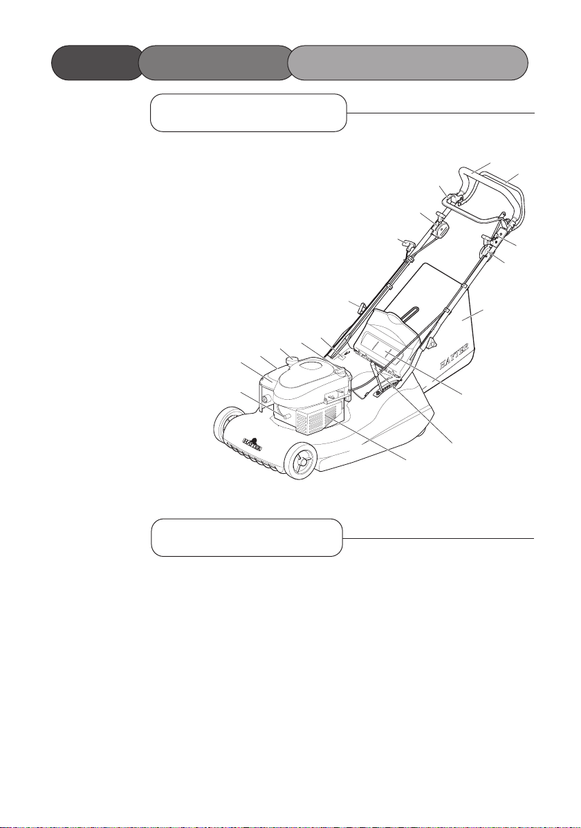
1. Spark Plug Lead.
2. Engine Cover.
3. Air Cleaner.
4. Fuel Filler Cap.
5. Oil Filler Cap and Dipstick.
6. Serial No.Label.
7. Handlebar Securing Knob.
8. Engine Start-Grip.
9. Throttle Control
10. BBC Control Lever.
11. Handlebar.
12. Ground Drive Clutch Lever
13 Blade Stop Lever
14. Variable Speed Control ( see note )
15. Grassbag Assembly.
16. Deflector.
17. Height of Cut Adjuster
18. Exhaust Guard
Note: Item 14 should only be operated whilst the engine is running or the cable will be damaged.
Page 3

1st Year (12 months)
We certify that this service has been
carried out by an Authorised Hayter
Service Dealer
Date:
1st Year (12 months)
Owner’s Name:
Serial Number:
Date:
2nd Year (24 months)
We certify that this service has been
carried out by an Authorised Hayter
Service Dealer
Date:
Owner’s Name:
Serial Number:
Date:
Note for dealer: Please retain this voucher for your records.
Note for dealer: Please retain this voucher for your records.
2nd Year (24 months)
Page 4

Page 5

1.2 Main Features/Specifications
1.5 Contents
1.6 Introduction
1.7 Warranty
1.8 - 1.11 Safety Precautions
1.8 - Training
1.8 - 1.9 - Preparation
1.9 - 1.10 - Operation
1.10 - 1.11 - Maintenance and Storage
1.11 - Safety Symbols
1.11 - Decal Symbols
1.12 Assembling the Mower
1.12 - Delivery Checklist
1.12 - Handlebar
1.12 - Grassbag Assembly
1.13 Before Starting the Mower
1.13 - Prevent Engine Damage
1.13 - Oil Type
1.13 - Check Oil Level
1.13 - Fuel Type
1.14 - 1.21 Operating The Mower
1.14 - Controls
1.14 - 1.15 - Starting
1.15 - Enagaging Cutterblade Drive
1.16 - Forward Travel
1.16 - Reverse Travel
1.16 - Turning
1.17 - Stopping
1.17 - Slopes
1.17 - Height of Cut
1.18 - Before Mowing
1.18 - Grassbag
1.18 - Without Grass Collection
1.19 - Heavy Growth
1.19 - Blade Brake Clutch
1.19 - Non-Grassed Areas
1.20 - 1.21 - Lawn Care Calendar - Guide Only
1.21 - Lawn Stripes
1.22 Maintenance Schedule
1.23 - 1.30 Mower Maintenance
1.23 - Engine
1.23 - Throttle Cable Adjustment
1.23 - Carburettor Adjustments
1.24 - Oil Service
1.24 - Air Cleaner Service
1.25 - Spark Plug Service
1.25 - Keeping Engine Clean
1.25 - Grassbag
1.26 - Deck Housing
1.26 - Securing Nuts and Bolts
1.26 - 1.27 - Clutch Cable Adjustment
1.27 - Lubrication
1.28 - Cutterblade Removal
1.28 - Cutterblade Assembly
1.29 - Cutterblade Sharpening
1.30 - Storage
1.32 - 1.33 Trouble Shooting
1.34 Declaration of Conformity
1.36 - 1.41 Parts List
1.36 - Parts List - Upper
1.37 - Exploded View - Upper
1.38 - 1.40 - Parts List - Lower
1.39 - 1.41 - Exploded View - Lower
1.42 - 1.43 Notes
1.44 Customer Info/Notes
CONTENTS
1.5
Page 6

INTRODUCTION
1.6
Thank you for purchasing a Hayter mower. The following pages are designed to help you gain
safe and efficient service from your machine.
IMPORTANT: This ‘Owners Handbook’ should be regarded as part of the mower as it gives
essential information regarding mower safety, operation, maintenance and specifications. Read
and understand this handbook prior to operating your mower for the first time. Make sure you
are familiar with all the controls and points of regular maintenance. If you have any doubts,
consult your local Hayter authorised dealer who will be pleased to give you assistance.
IMPORTANT: This mower is designed solely for use in a domestic grass cutting
environment. Use in any other way is considered as contrary to the intended use. Compliance
with and strict adherence to the conditions of operation, service and repair as specified in this
handbook also constitute essential elements of the intended use.
This mower should be operated, serviced and repaired only by persons who are familiar with
its particular characteristics and who are acquainted with the relevant safety procedures.
The safety precautions listed in this handbook and all other generally recognised regulations on
safety must be observed at all times.
Any arbitrary modifications carried out to this machine may relieve Hayter Limited of
liability for any resulting damage or injury.
Hayter mowers are robustly constructed and designed for efficient economical
performance under normal mowing conditions. Correct operation and maintenance will ensure
a long and satisfactory service life. Prior to despatch from our factory every effort is made to
ensure that your mower is delivered in perfect condition.
Throughout this handbook all references to left and right are as viewed from behind the
handlebar, in the direction of forward travel.
This handbook is based on information available at the time of publication.
HAYTER LIMITED reserve the right to amend product specifications without prior notification.
Page 7

WARRANTY
1.7
LIMITED WARRANTY
Hayter Limited warrants to the original user/purchaser that this unit shall be free from defects
in material and workmanship under normal use and service for a period of three years from the
date of purchase. The manufacturer of major proprietry components ie. engines, gearbox /
transaxle (where applicable) furnish their own warranty and services are provided through their
authorised network. To qualify for the full benefit of the warranty, the warranty registration card
must be returned within 14 days of purchase. Subject to the conditions and exclusions noted in
this limited warranty, we shall at our option, repair or replace any warranted part during the
applicable period. If you are in doubt or experience any difficulty, please consult a Hayter
Authorised Service Dealer for clarification.
To qualify for the extended warranty (second and third year) of the three year limited warranty
the machine must have annual services carried out by an Authorised Hayter Service Dealer.
These chargeable services should be carried out within 12 and 24 months of the date of purchase.
Excluded from the extended warranty period are those items which are subject to normal wear
and tear e.g. tyres, wheels, cutterblades, belts, cables, grassbags, sweeper/brushes, batteries and
other consumable wearing parts.
All consumer machines which are fitted with a genuine Hayter friction disc as original
equipment before use, are covered by a Lifetime Warranty against the engine crankshaft
bending. Note: friction washers, blade brake clutch (B.B.C) units and other such devices are not
applicable. Only machines fitted with a genuine Hayter friction disc, which are used in
accordance with the recommended operating and maintenance procedures, are covered.
This warranty does not apply to any unit that has been tampered with, altered, misused, abused or
used for hire, and will become invalid if non genuine Hayter parts are fitted. This warranty does
not cover minor mechanical adjustments unless they are due to defective material or
workmanship. Consult the Owner’s Handbook or a Hayter Authorised Service Dealer for
assistance when making these adjustments.
A warranty period of 90 days applies to machines used for commercial purposes.
To make a warranty claim, return the unit to a Hayter authorised dealer along with proof of
purchase stating the machine serial number and date of purchase. The service receipt(s) or this
Owners Handbook with the 1st/2nd year service boxes fully completed, must be produced as
proof of entitlement to the extended warranty period. Subject to the conditions and exclusions in
this limited warranty, the authorised dealer will, at our option, repair or replace any warranted
part within the duration of the warranty period.
This limited warranty gives you specific legal rights and is in addition to any statutory rights to
which you may be entitled and your statutory rights are not affected by this warranty. If you need
additional information concerning this written warranty, or assistance in obtaining services,
please write to : HAYTER LIMITED, Service Department, Spellbrook, Bishop’s Stortford,
Hertfordshire CM23 4BU
UK ONLY: Details of your local Hayter authorised dealer are contained in Yellow Pages and
the Hayter website www.hayter.co.uk or contact contact:- Freephone 0800 616298.
Issue: 05.09.03
Page 8
SAFETY PRECAUTIONS
1.8
This safety alert symbol indicates important safety messages. When
you see this symbol be alert to the possibility of injury. Carefully read
the following and inform others.
Your mower is perfectly safe if used correctly. Failure to observe the
following precautions may result in serious injury.
Before using the mower read the owners handbook carefully. Pay particular attention to the safety precautions. Ensure that you are familiar
with the controls and the proper use of the equipment. Learn how to
stop the mower quickly in an emergency.
Never allow children or people unfamiliar with these instructions to
use the mower.
Never mow while people, especially children, or pets are nearby.
Keep in mind that the user is responsible for accidents or hazards
occurring to other people or their property.
While mowing, always wear substantial footwear and long trousers.
Do not operate the equipment when barefoot or wearing sandals.
Thoroughly inspect the area where the mower is to be used and remove
all objects which may be thrown by the machine.
WARNING: Petrol is highly flammable.
- Store fuel in containers specifically designed for this purpose.
- Before starting the engine add fuel outdoors only. Never remove the
cap from the fuel tank or add petrol while the engine is running or
when the engine is hot. Allow the engine to cool for at least two minutes before refuelling. Do not smoke while refueling.
- Do not attempt to start the engine if petrol is spilled or a smell of
petrol is present. Move the mower away from the area of spillage
and avoid creating any source of ignition until petrol vapours have
dissipated.
Replace faulty silencers.
Safety Alert Symbol
Preparation
Training
Page 9

PRECAUTIONSSAFETY
1.9
- Always use fresh fuel. Stale fuel can block the carburettor and cause
leakage.
- Replace fuel tank and oil tank caps securely.
A damaged cutterblade or loose fixing bolt are major hazards. Before
use, always visually inspect the cutting mechanism to ensure that it is
in good condition. A damaged cutterblade must be replaced
immediately with a genuine Hayter replacement part.
Do not operate the engine in a confined space where exhaust fumes
(carbon monoxide) can collect. Refuel outdoors only and do not smoke
while refuelling.
Always pull the starter cord slowly until resistance is felt. Then pull the
cord rapidly to avoid kickback and prevent hand or arm injury.
Mow only in daylight or good artificial light.
Avoid using the mower on wet grass, where feasible.
Always be sure of your footing on slopes.
Walk, never run.
Mow across the face of slopes, never up and down.
Exercise extreme caution when changing direction on slopes.
Do not mow excessively steep slopes of more than 20 degrees.
Use extreme caution when reversing or pulling the mower towards you.
Stop the engine before moving the mower across areas other than grass.
Never operate the mower unless the guards are securely in position and
in good condition.
Do not change the engine governor settings or overspeed the engine.
Disengage the rear roller drive clutch before starting the engine.
Start the engine carefully, with feet well away from the cutterblade.
Operation
Preparation
Page 10
1.10
Do not tilt the mower when starting the engine.
Do not put hands or feet near or under rotating parts.
Never pick up or carry the mower while the engine is running.
Never lift the rear deflector while the engine is running.
Never touch the exhaust/exhaust guard or cooling fins when the engine
is hot.
Stop the engine and disconnect the spark plug lead:
- Before clearing blockages or unclogging the discharge chute.
- Before cleaning/checking or working on the mower.
- After striking a foreign object. Inspect the mower for damage and
ensure necessary repairs are made before re-starting.
- If the mower starts to vibrate abnormally (check immediately).
Stop the engine:
- Whenever you leave the mower.
- Before refuelling.
Reduce throttle control setting during engine shutdown.
Keep all nuts, bolts and screws tight to ensure that the equipment is in
safe operating condition.
Frequently check fuel lines and fittings for cracks or leaks and replace
if necessary.
Never check for a spark when the spark plug is removed. (Use approved
tester)
Inspect the exhaust periodically and replace if worn or leaking.
Never crank the engine with the spark plug removed.
Never start the engine with the air-cleaner or air-cleaner cover
removed.
Never store the mower with petrol in the tank within an enclosed area
where fumes may reach an open flame or spark.
Operation
Maintenance & Storage
SAFETY PRECAUTIONS
Page 11
1.11
Allow the engine to cool before storing in any enclosure. To reduce
the fire hazard, keep the engine and the surrounding deck area free
of grass, leaves, or excessive grease.
Check the rear deflector and grassbag frequently for wear or deterioration.
Replace worn or damaged parts for safety.
If the fuel tank has to be drained, this should be done outdoors and when
the engine is cool.
Wear strong work gloves when removing and reassembling the cutterblade.
Always replace worn or faulty parts with genuine Hayter parts.
This machine contains spring loaded assemblies which could cause a hazard when dis-assembled and
re-assembled, this maintenance should only be carried out by a Hayter authorised dealer.
Maintenance & Storage
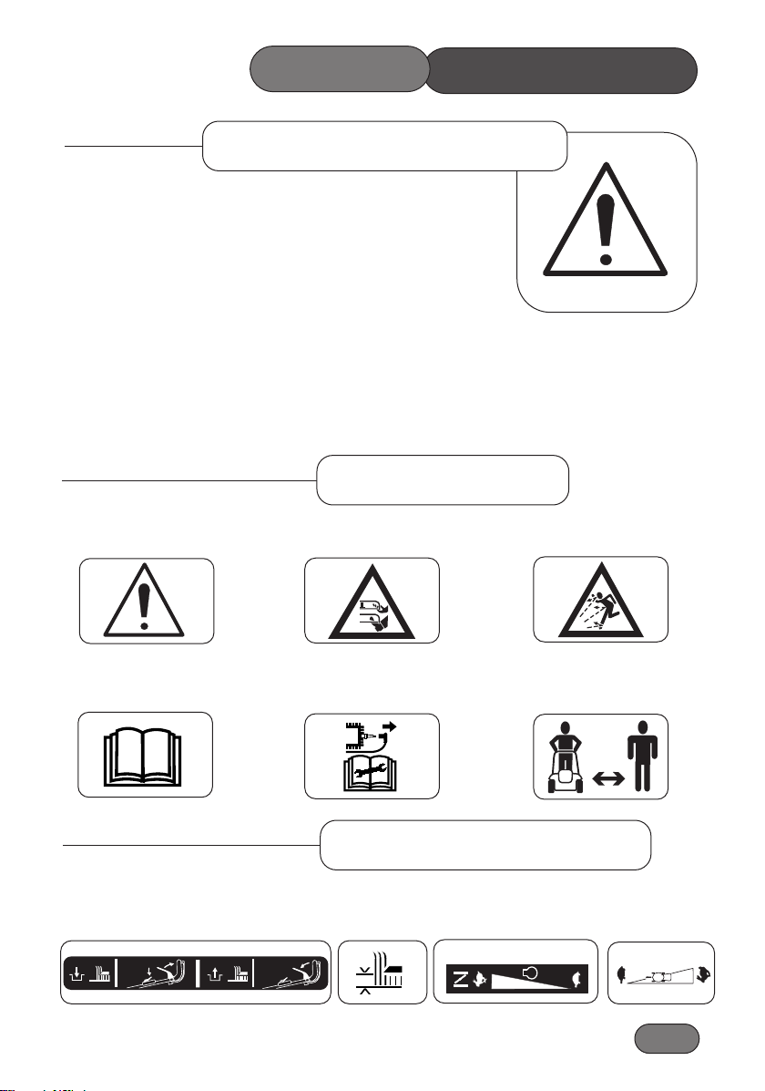
Safety Symbols
Safety Alert - Be aware to the
possibility of injury.
Danger of severing toes or
fingers in cutting mechanism.
Carefully read the Owners
Handbook before using the
machine.
Danger of being hit by thrown
objects.
Stop engine and remove spark
plug lead before working on
the mower.
Keep bystanders at a safe
distance from the mower.
Height of Cut Adjustment
(Symbol)
Throttle Control
(Symbol)
Information Symbols
11
2
1
111-0745(A)
305113
Choke Fast Slow
Variable Speed Control
(Symbol)
56Cth13a
Cutterblade
Engage
Cutterblade
Disengage
Slow Fast
PRECAUTIONS
SAFETY
Page 12
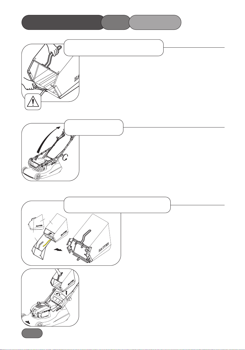
1.12
Remove the mower from the packaging and check that the following
items have been supplied correctly. If any items are missing contact,
your local Hayter dealer.
1. Engine Handbook.
2. Grassbag.
To prevent accidents cut off the long ribbon attached to the grassbag and discard.
Unscrew the handlebar securing knobs sufficiently to allow the handlebar to pivot. Move the engine stop lever away from the engine to avoid
damage and unfold the handlebar to the operating position.
Make sure the knobs are assembled to the outside of the hanadlebar and
tighten to secure into position.
Take care to ensure that the control cables do not become snagged at
the pivot point.
Before first use, assemble the grassbag and
frame.
Slide the frame (1) into the grassbag (2), ensuring
that the handle is above the grassbag as shown.
Attach plastic clips (A), (B), (C) and (D) to the
grassbag frame.
Raise the rear deflector, lower the grassbag and hook in position.
Lower the deflector to rest on the grassbag.
HAY-G00114-A
B
A
C
D
1
2
Handlebar
Delivery Checklist
Grassbag Assembly
ASSEMBLING THE MOWER
56CTH03B
Page 13
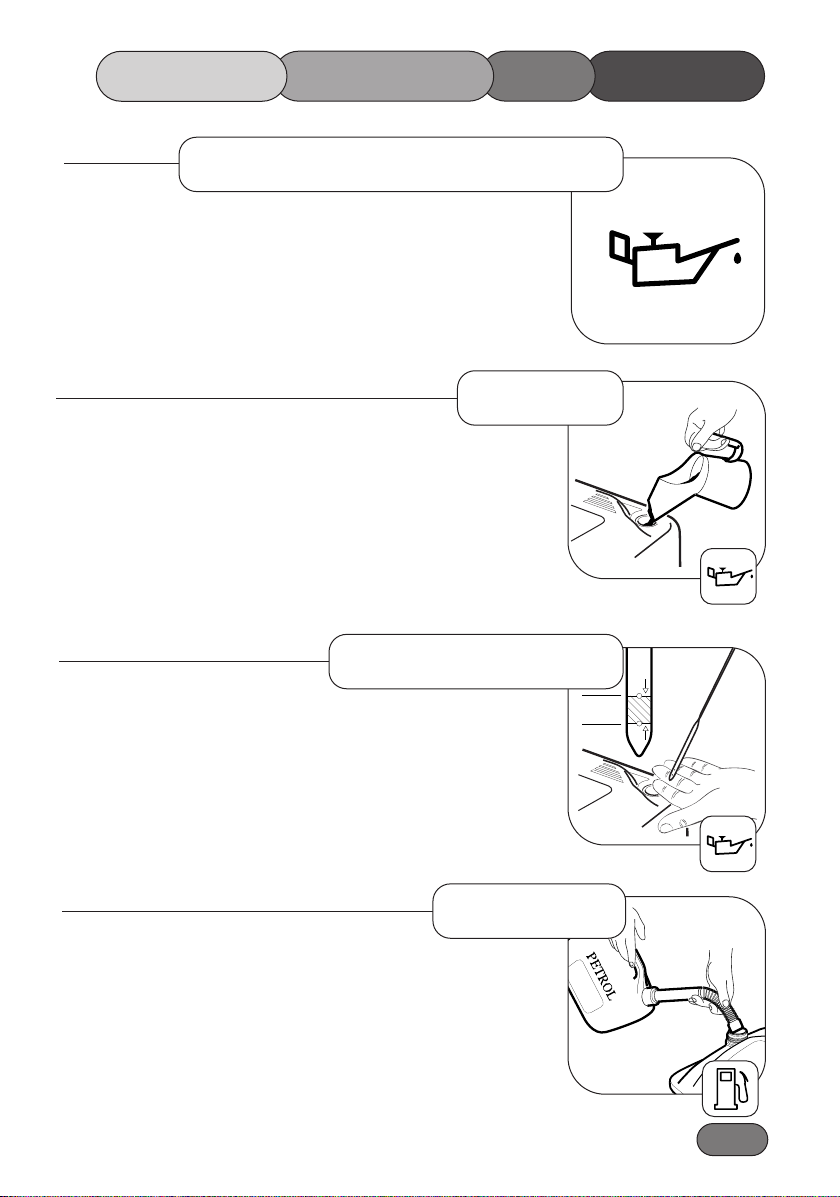
1.13
To prevent engine damage the engine is shipped without oil or
petrol. The engine must be filled with the correct grade of oil and
petrol before starting the engine.
Always use high quality detergent oil classified SAE 30 oil. Never use
additives with recommended oil.
To prolong the life of your engine it is important that the oil is changed
after the first 5 hours of use - refer to ‘Maintenance Schedule’.
Clean around the oil filler cap before removing. With the mower on a
level surface, unscrew and remove the oil filler - dipstick. Wipe oil
from it with a clean cloth. Screw the oil filler - dipstick back in place,
then unscrew and remove it to check the oil level.
The oil level is correct when it is at the full mark on the dipstick.
DO NOT OVERFILL.
Always use clean, fresh unleaded petrol. Purchase fuel in quantities
that can be used within 30 days. Never mix oil with petrol. For added
engine protection Briggs & Stratton recommend the use of their fuel
additive which is available from an authorised Briggs & Stratton service dealer.
Fill to base of neck to allow for fuel expansion. Do not overfill the
fuel tank.
Prevent Engine Damage
O
I
L
ADD
FULL
0.15
Litres
Oil Type
Check Oil Level
Fuel Type
MOWERTHESTARTING
BEFORE
Page 14
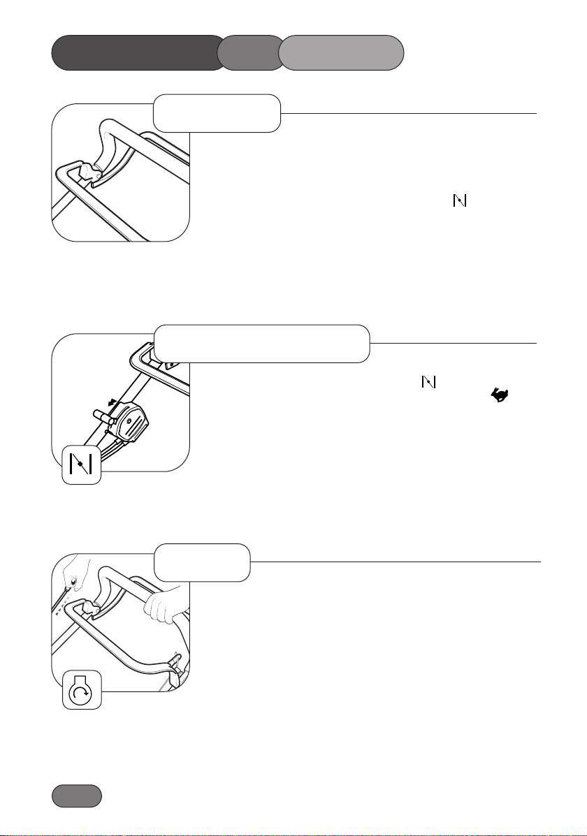
1.14
Operate all control levers several times and ensure that the cables
move freely. Check that the cutterblade stop and ground drive clutch
levers return freely to their rest position when released.
Whilst operating the engine throttle mechanism slight resistance
should be felt when moving the lever to the ‘choke’ position.
IMPORTANT: To avoid damage to the cable the Variable speed
Control should only be operated whilst the engine is running.
Move the throttle control lever to the ‘choke’ position before starting a cold engine. Move the throttle control lever to the ‘fast’ posi-
tion before starting a warm engine.
Stand behind the mower and hold the handlebar with your left hand.
With your right hand hold the engine start - grip and pull slowly until
resistance is felt, then pull rapidly to crank the engine. Carefully return
the start grip to the storage position when the engine starts.
If the engine does not start after 5 attempts - refer to “Trouble
Shooting”.
Note: The cutterblade is not engaged at this stage.
Controls
Starting - Step 1
Step 2
OPERATING THE MOWER
Page 15
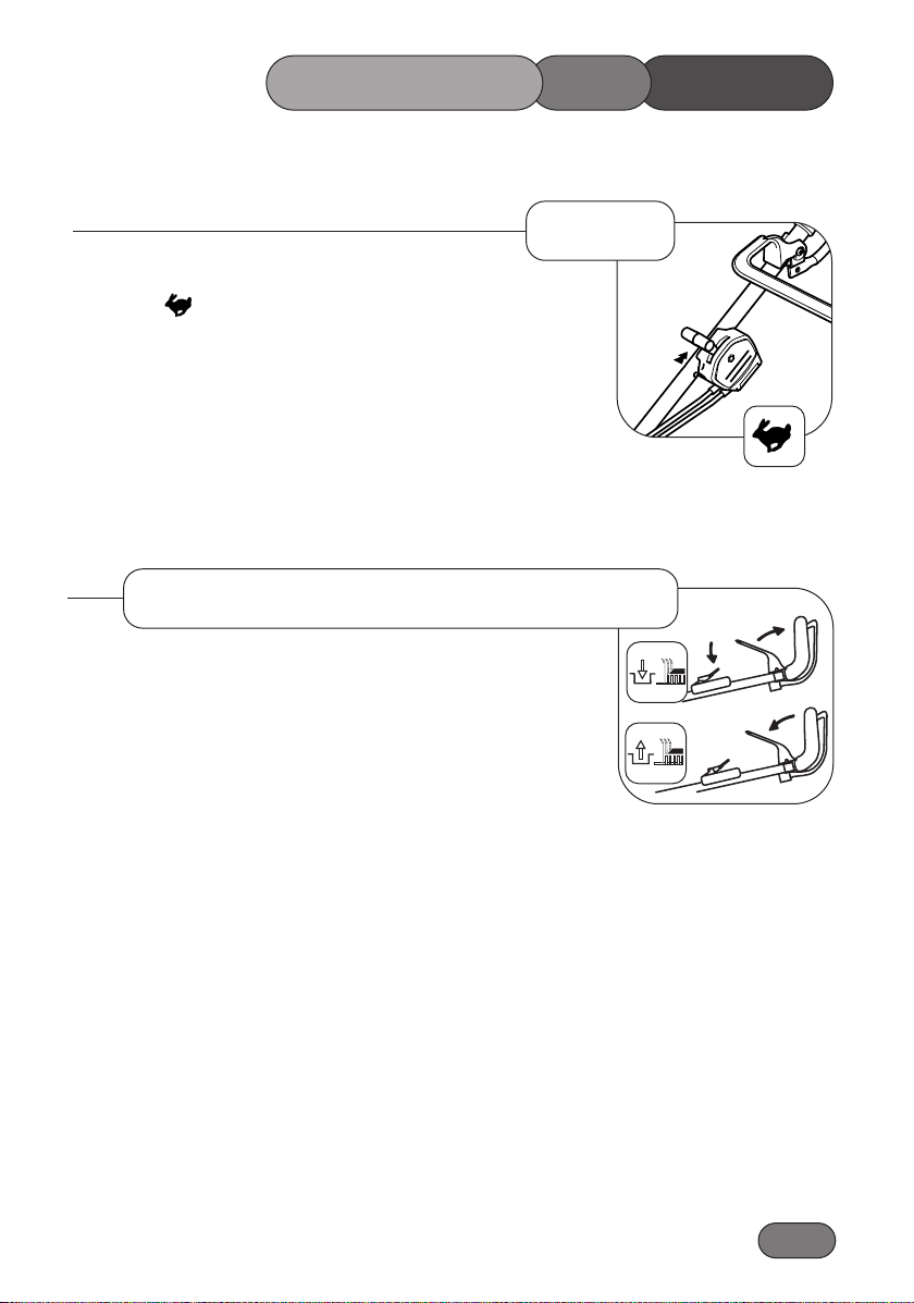
1.15
Allow the engine to warm up and move the throttle lever to the
‘fast’ position after starting a cold engine.
To prevent damage never pull the engine start grip when the
engine is running.
Always make sure the stop lever is fully forward.
(1) To engage the (BBC) cutterblade first push the switch actuating lever downward.
(2) Pull the blade stop lever back against the handlebar at the
same time, and hold in position.
Disengage Cutterblade Drive.
(1) Release the blade stop lever and it will return to its rest
position.
Emergency Stop.
If the cutterblade drive mechanism fails stop the engine.
1
2
1
Engaging Cutterblade Drive
Step 3
MOWERTHEOPERATING
Page 16
1.16
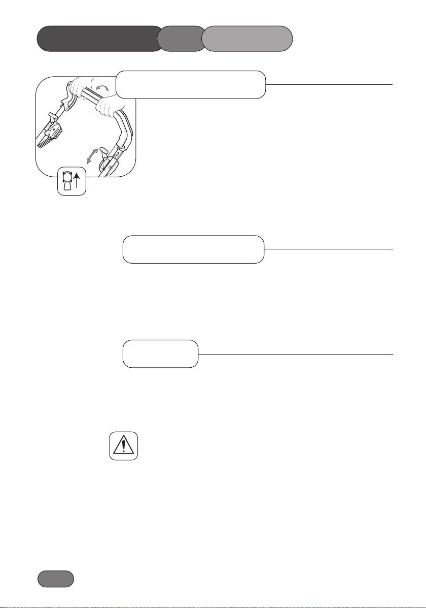
Hold the handlebar and operate the ground drive clutch lever to power
the mower in a forward direction.
When the ground drive clutch lever is disengaged the mower may be
pushed. This feature is useful when mowing in confined areas.
Ground speed may be adjusted by operating the speed variator control.
Push forward to slow down and pull back to speed up. Only operate the
lever with the engine running to prevent damage.
If the cutterblade stop lever is released the cutterblade will stop.
Hold and pull against the handlebar with both hands to reverse the
mower.
To make a wide turn steer the mower with the handlebar in the direction required.
To make a tight turn release the ground drive clutch lever, apply downward pressure on the handlebar to raise the front wheels just above
ground level and steer in the required direction.
To prevent accidents do not raise the front of the mower excessively when making a turn. Never raise the rear of the mower
when the engine is running.
Turning
1CG480V01B
Forward Travel
OPERATING THE MOWER
Reverse Travel
Page 17
1.17
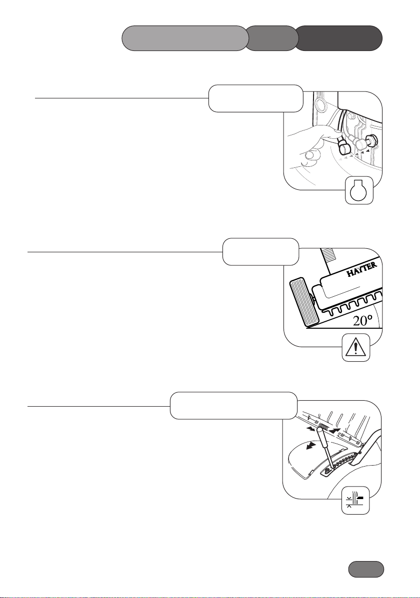
Release both ground drive clutch lever and the cutterblade stop lever.
Pull the throttle lever to the rear most position.
Emergency stop If the engine fails to stop, disconnect the spark
plug lead.
To prevent engine damage do not use the mower on slopes greater
than 20 degrees.
To adjust the height of cut: Grip the lever and pull sideways to
disengage it from the locking notch, then push forwards to lower or
pull backwards to raise the height of cut. Finally release the lever at
the required position and ensure it locks firmly into one of the eight
setting notches.
Always select a height of cut to suit operating conditions. Aim to
prevent engine overloading and blockages by avoiding low cuts in
long grass conditions. Be prepared to make two cuts when the grass is
long.
Height of Cut
305113
Slopes
Stopping
STOP
MOWERTHEOPERATING
Page 18
1.18
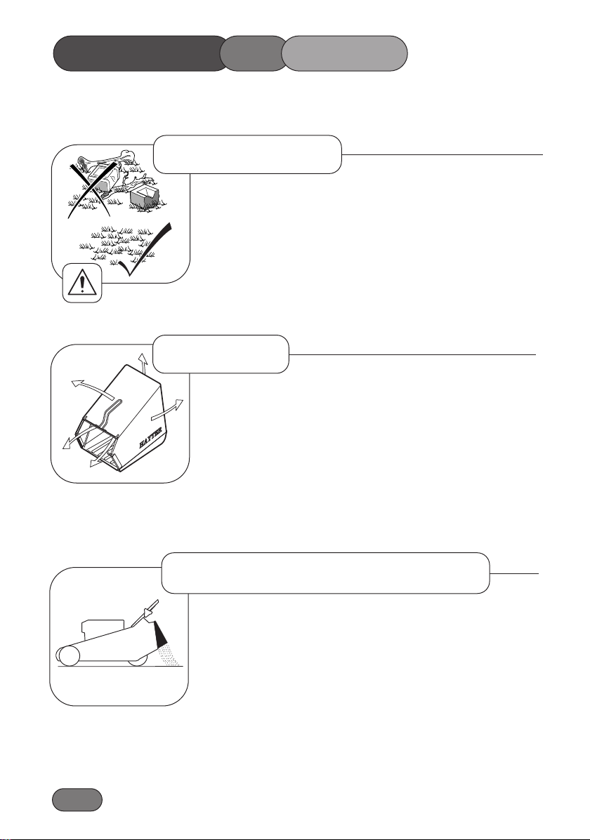
To prevent accidents, thoroughly inspect the area and
remove all objects which when contacted by the mower cutterblade could become dangerous projectiles. Inspect the
area for hidden obstructions which when contacted by the
cutterblade could risk health and safety or result in damage
to the mower. Remember the location of these obstructions
and ensure that you mow around them.
Raise the rear deflector and lift the grassbag and lower the rear
deflector to rest against the rear of the mower.
To empty the grassbag, pour out the grass clippings and shake
the grassbag vigorously to clean the airways. Good grass collection depends on good air flow through the grassbag. When
collecting grass clippings it is important that the grassbag is
emptied regularly to prevent blockages and engine overloading.
Remove the grassbag and operate the mower with the rear
deflector in the closed position.
CS386
Without Grass Collection
56CTH11B
Grassbag
Before Mowing
OPERATING THE MOWER
Page 19
1.19
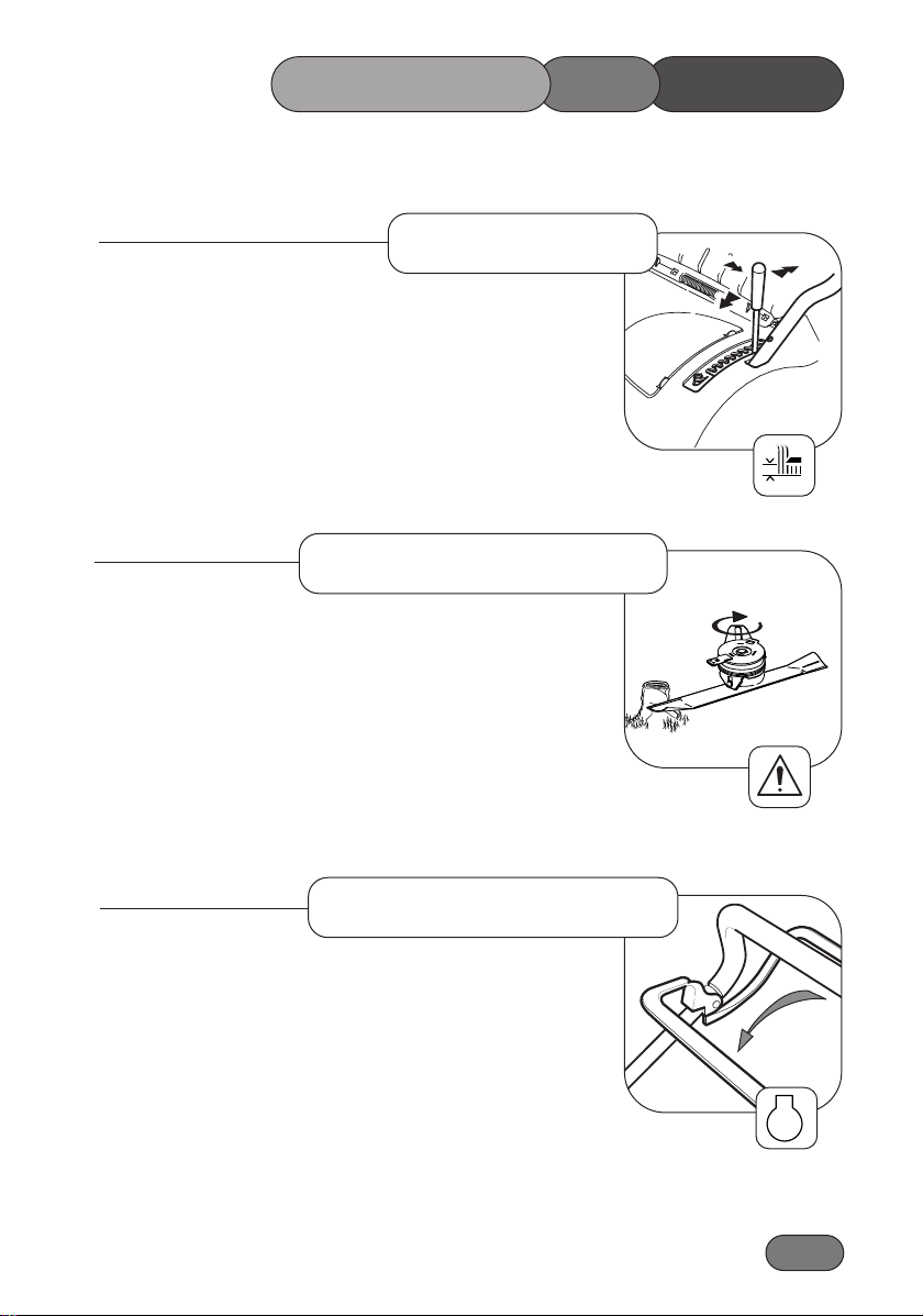
Areas of heavy growth should be mown without collecting the
clippings. If collection is required, first mow the area without the
grassbag at the maximum height of cut setting. Allow the grass
clippings to dry out and then mow the area at the maximum height
of cut setting with the grassbag fitted. Reduce the height of cut and
mow the area again as necessary until the required finish is
obtained.
To prevent damage to your lawn do not remove more than one third
of grass height in one cut.
A device in the blade brake/clutch helps minimise damage to the
cutting mechanism when a hidden obstruction or overload is
encountered. When the obstruction or overload is removed,
the device will automatically reset.
Always stop the engine when a hidden obstruction or excessive
vibration is encountered. Disconnect the spark plug lead and
examine the cutting mechanism. ALWAYS replace a damaged
cutterblade - refer to “Maintenance”.
When moving the mower across non-grassed areas, stop the
cutterblade and set the mower to the maximum height of cut to
protect the cutting mechanism.
Non-Grassed Areas
STOP
Heavy Growth
Blade Brake Clutch
305113
MOWERTHEOPERATING
Page 20

1.20
There is very little work to do this month apart from brushing away
leaves. Keep off the grass if frozen or waterlogged.
Rake the grass thoroughly. Spike the lawn to aerate and stimulate soil
organisms and root growth and apply lawn sand if necessary.
The yearly lawn work programme really starts this month. As soon as
the ground conditions are suitable, the first cut can be made. The first
cut should merely “top” the grass as close cutting at this stage could
result in severe yellowing or browning. Two cuts are generally
sufficient this month.
Mow often enough to stop grass growing away. Dig out patches of
coarse grass or resistant weed. Re-seed bare patches.
Keep mowing increasing the frequency as required. Treat with
selective weed killers or combined weed/feed preparations if you did
not feed the lawn in April.
Summer mowing should now be under way. It should be necessary to
mow the lawn twice a week. Raking before mowing is important this
month as the combined action keeps runners of clover under control.
Water the grass if necessary, and remember to soak thoroughly.
Treat the grass with the second application of fertiliser or weed
killer/fertiliser. Water when necessary and rake occasionally. As a
general rule the grass clippings should be removed each time you
mow. If weather conditions are dry and hot and the grass is weed free,
leave the clippings on the lawn to help maintain ground moisture.
January
LAWN CARE CALENDAR
February
March
April
May
June
July
To be used as a guide only.
Page 21
Keep mowing regularly and watering as necessary. Fill any cracks
caused by drought with a mixture of sharp sand and soil. In dry weather conditions leave the grass longer to help retain ground moisture.
Raise the height of cut to allow the grass to thicken and protect the roots
from the winter frost and snow.
Rake out the thatch from the turf and spike the lawn to assist in
drainage. Brush in peat and sharp sand.
Use a stiff broom to disperse worm casts before mowing. Keep turf free
from leaves.
Apart from brushing away leaves, December is a slack end of a busy
year. Keep off the lawn if it is very wet or frozen.
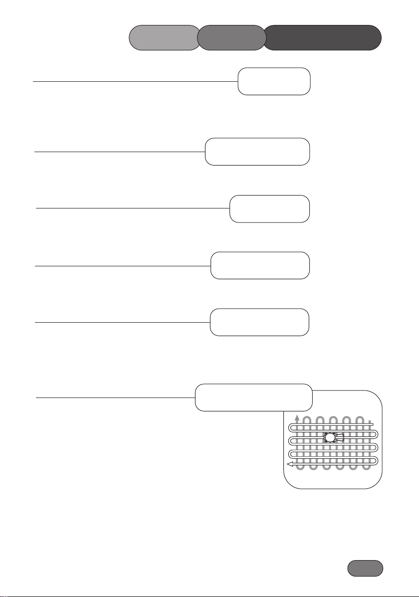
The way to achieve a neat striped effect is for the lawn being cut in
parallel stripes, alternate stripes being mown in opposite directions.
A much more important routine is to cut at right angles to the line of
the previous mowing. If the work has been carried in a north-south line,
then the next cutting should be in an east-west direction. The
cross-cutting keeps down the coarse weed grasses.
To prevent grass damage do not remove more than one third of the
grass height in one cut.
1.21
CALENDAR
August
LAWN CARE
September
October
November
December
1
2
1CG480V05A
Lawn Stripes
Page 22

1.22
Follow the hourly or calendar intervals, whichever occurs first. More
frequent service will be required if working for prolonged periods
under dusty, dry conditions, or when airborne debris is present or after
extensive operation cutting tall, dry grass.
After the very first five hours change the engine oil
Check the oil level
Remove grass debris from around the engine, exhaust/exhaust guard, air
ways in the top cowl and underside of the deck housing.
Remove grass debris from the grassbag and check for signs of damage.
Check the condition of guards and safety devices.
Check condition of cutterblade.
Change the engine oil if continuously operating under heavy load or
high ambient temperature.
Service the air cleaner.
Lubricate wheels, pivot points and linkages and grease the inner control cables at point of entry and exit from their outer casing.
Check the clutch cable adjustment.
Sharpen the cutterblade.
Change the engine oil.
Clean the engine cooling system. Clean more often under dusty conditions or when airborne debris is present or after prolonged operation
whilst cutting tall, dry grass.
Replace the spark plug.
MAINTENANCE SCHEDULE
100Hrs or Every Season
25Hrs or Every Season
Daily
50Hrs or Every Season
First 5Hrs
Page 23
1.23
To prevent accidents stop the engine and disconnect the spark plug
lead before attempting to carry out maintenance procedures on
the mower.
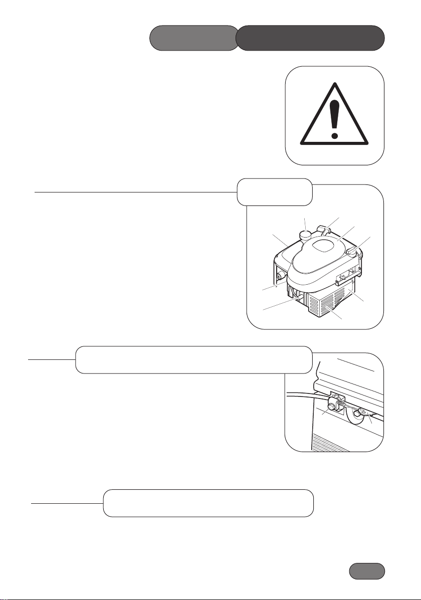
1. Air Cleaner
2. Fuel Cap
3. Start Grip
4. Cover
5. Oil fill/Dipstick
6. Exhaust Guard
7. Exhaust
8. Spark Plug / Lead
9. Carburettor
Loosen casing clamp screw (1) and move the governor lever (2) in the
direction of screw (1) as far as possible. Move the throttle control to
the choke position. Tighten casing clamp screw.
Should only be made by an authorised Briggs & Stratton dealer. Under
no circumstances should the engine be adjusted to run at a speed in
excess of that shown on the Declaration of Conformity.
MOWER
7
1
8
9
6
5
3
4
2
2
1
Engine
Throttle Cable Adjustment
Carburettor Adjustments
MAINTENANCE
Page 24
1.24
Check the oil level daily before starting the engine and ensure that the
correct oil level is maintained. Refer to-‘Before Starting the Mower’
for oil checking and filling instructions.
Change the engine oil after the first 5 hours of operation and thereafter
according to the ‘Maintenance Schedule’:-
1. Drain fuel by running the engine until the fuel tank is empty.
2. Remove the spark plug lead.
3. Allow the engine to cool.
4. Drain the oil while the engine is warm (not hot).
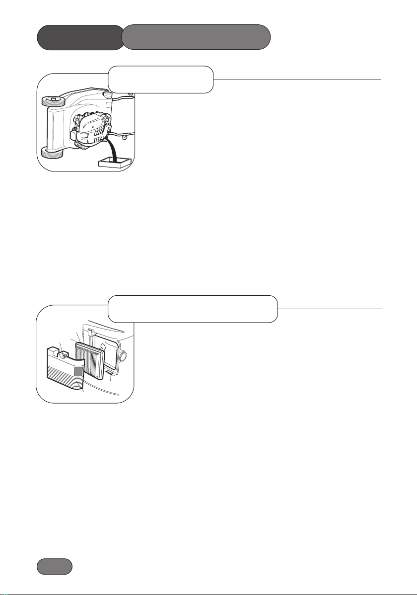
5. Tip the mower over on to its left hand side thus ensuring that
the air cleaner is kept uppermost to prevent engine damage.
6. Remove the oil filler dipstick and drain the oil into a suitable
container.
7. Refill with new oil of the recommended SAE viscosity grade.
(Refer to-‘Before Starting the Mower’)
To service the air cleaner, loosen screw (1) and remove cover (2).
Remove cartridge (3) and clean by tapping gently on a flat surface.
If very dirty, replace.
- Do not use petroleum solvents.
- Do not use pressurised air.
- Do not oil the cartridge.
After servicing, install the cartridge into the cover. Insert the tabs on
the bottom of the cover into the slots in the bottom of the base (4). Tilt
the cover upwards and securely tighten the screw to the base.
MOWER
3CG
1
2
3
4
Oil Service
Air Cleaner Service
MAINTENANCE
Page 25
1.25
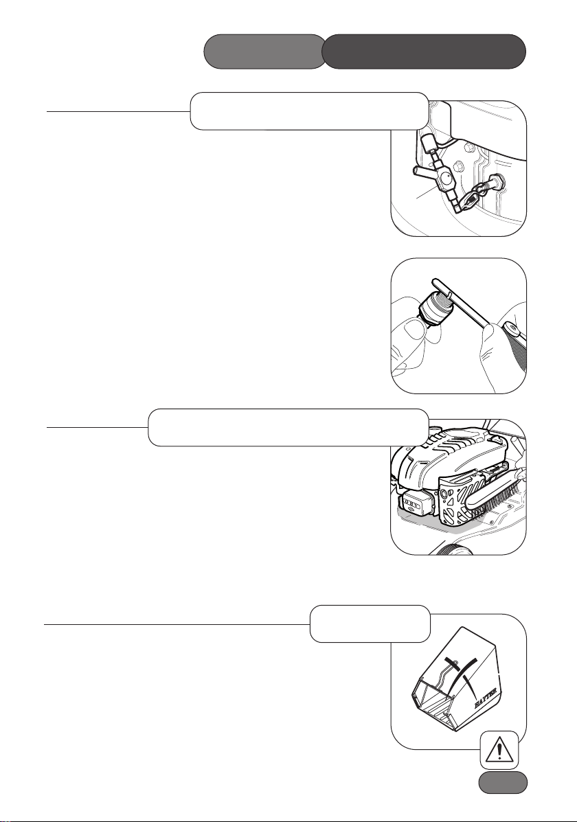
Use only Briggs & Stratton spark tester (1) to check for a spark as
shown in the diagram.
Replace the spark plug every 100 hours or every season, whichever
occurs first. A spark plug wrench is available from any authorised
Briggs & Stratton service dealer.
Check the spark plug gap with a feeler gauge and set at 0.76mm.
Remove all grass and debris from the engine including the
exhaust/exhaust guard, the air ways in the top cowl and the surrounding deck areas on a daily basis after use. Never spray the engine with
water during cleaning. Water can contaminate the fuel. Always clean
with a brush or compressed air.
Grass and debris may clog the engine’s air cooling system especially
after prolonged operation while cutting tall, dry grass. The internal cooling fins and surfaces may require cleaning to prevent overheating and
engine damage. We recommended that this service be carried out by an
authorised Hayter Service dealer.
Remove grass debris from the grassbag immediately after use and
check its condition for signs of damage.
To prevent accidents replace a damaged grassbag immediately.
56CTH12B
1
Spark Plug Service
Keeping Engine Clean
Grassbag
MOWER MAINTENANCE
Page 26
1.26
MOWER
MAINTENANCE
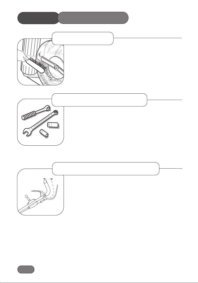
Remove grass debris from the top and underside of the deck housing
immediately after use.
Fertilisers and top dressings are particularly corrosive.
Thoroughly clean the mower deck immediately after use on treated grass and store well away from corrosive materials.
Regularly check that all securing nuts and bolts are tight. Replace
missing or damaged items immediately.
At any time the operator feels that the machine is loosing drive:
1. Stop the engine.
2. Pull the machine backwards at the same time progressively
engage the clutch lever until the rear rollers lock, at this point the
clutch lever should be 60mm from the handlebar. Refer to Fig 1.
60mm
1CG480V36B
Securing Nuts & Bolts
Deck Housing
Clutch Cable Adjustment
Fig. 1
Page 27
1.27
MOWER MAINTENANCE
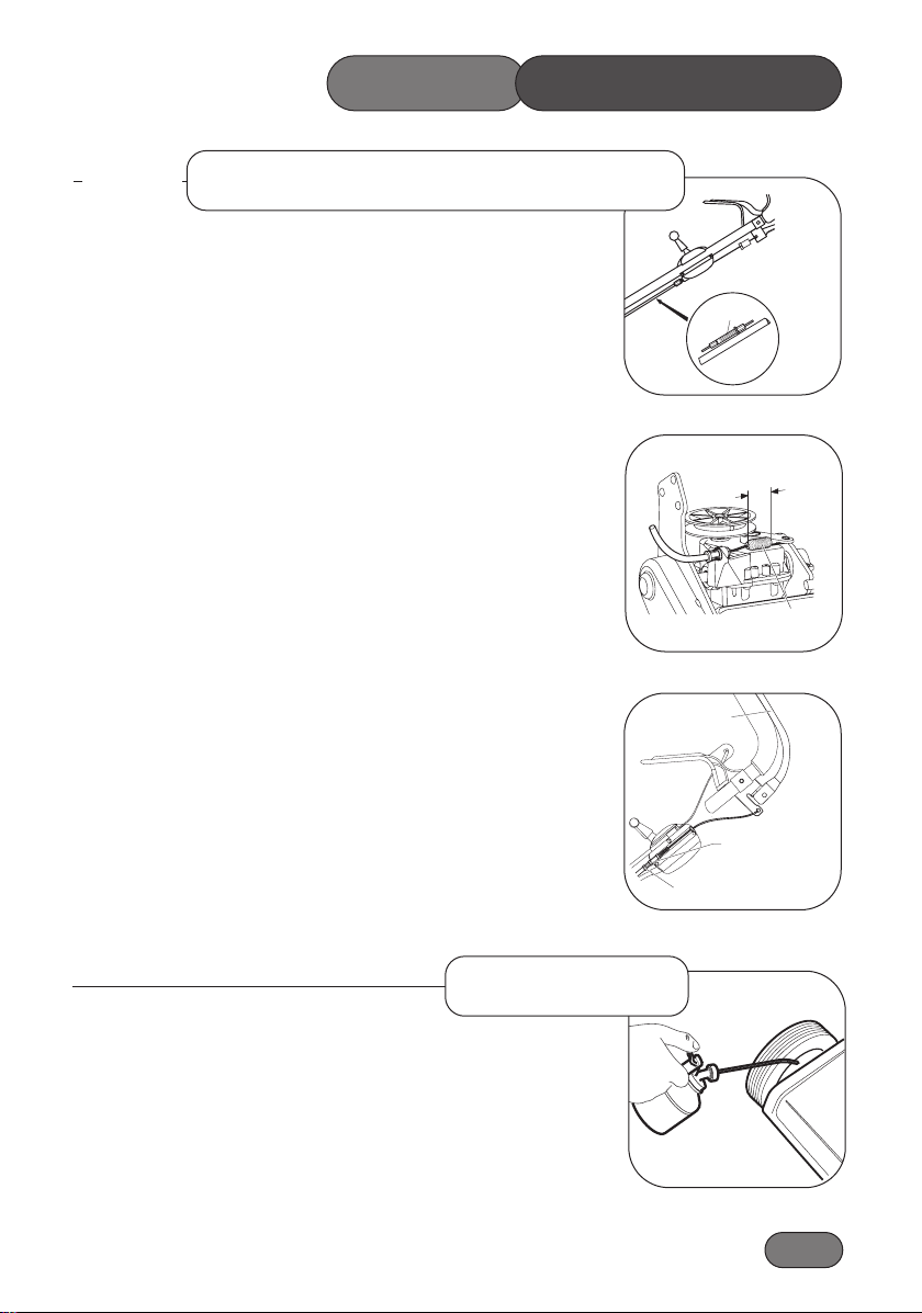
3. If the distance between the clutch lever and handlebar is less than
60mm regulate the engagement position with the black plastic
cable adjuster. Refer to Fig 1 and Fig 2 to regain the 60mm
distance.
4. Note this is a temporary adjustment and at the nearest
opportunity a service should be carried out to ensure the spring
on the clutch cable attached to the gearbox clutch. This
adjustment should be done using the metal adjuster at the control
with the plastic adjuster reset fully wound in. When the spring is
set tighten the inner lock nut to secure position.
Lubricate the wheels, pivot points and linkages with engine oil every 25
operating hours.
Apply a good quality medium grease to the inner control cables at the
point of entry and exit from their outer casing.
Lubrication
1
Fig. 2
Clutch Cable Adjustment
Continued
HAY-G00147-A
13mm
extension
Clutch
spring
Fig. 3
Tighten the inner
nut when the cable
spring is set.
Clutch lever
fully engaged
Metal
adjuster
HAY-G00146-A
Fig. 4
Page 28
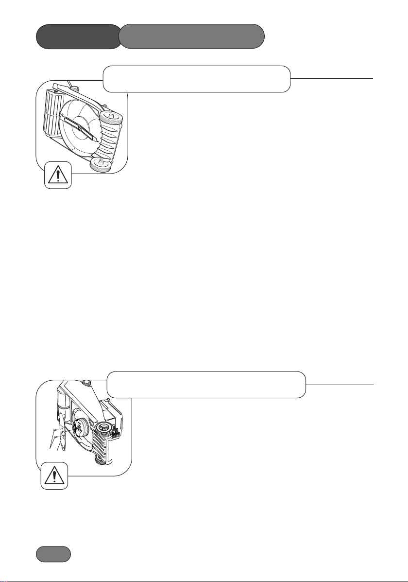
Drain the fuel by running the engine until the fuel tank is empty and the
engine stops. Remove the spark plug lead and allow the engine to
cool. Turn the mower on its left hand side and ensure that the air cleaner side of the engine is uppermost.
Firmly grip the end of the cutterblade with the gloved hand and remove
the bolt, spring washer and distance piece securing the cutterblade with
a 9/16” A/F spanner.
To prevent accidents never work on the cutterblade unless the
spark plug lead has been removed. The cutterblade has sharp
edges. ALWAYS wear strong gloves to protect your hands when
working on the cutterblade. DO NOT rotate tools towards the cutting edges to avoid the risk of injury should the tool slip. ALWAYS
use genuine Hayter replacement parts.
The condition of the cutterblade and its mounting arrangement should
be checked regularly for signs of wear or damage. Ensure that the cutterblade is not bent or cracked.
A damaged cutterblade that is out of balance will vibrate excessively
and may break. DO NOT use an unbalanced cutterblade.
Regularly check that the bolt securing the cutterblade is tightened to the
specified torque of 54Nm.
Replace the cutterblade every 2 years of sooner if excessively worn or
damaged.
To prevent injury it is wise to seek assistance when turning the mower
on its side.
Assemble the cutterblade (2) with the turned up edges facing towards
the engine. Secure the cutterblade using two new fixing screws and
tighten to a torque of 55Nm.
To prevent accidents never reuse the fixing screws.
MOWER
MAINTENANCE
1
2
Cutterblade Assembly
1.28
1CG480V33D
Cutterblade Removal
Page 29
1.29
MOWER MAINTENANCE
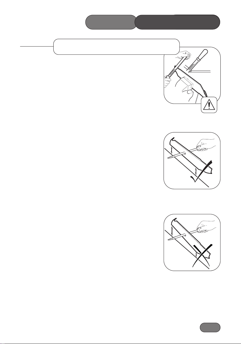
A slightly worn cutterblade may be re-sharpened. Both blade edges
must be sharpened equally to ensure balance. Sharpen the cutterblade
every 25 mowing hours or more frequently if conditions require.
Remove the cutterblade from the mower and clean using a brush and
water. Inspect the cutterblade for signs of damage.
Sharpen both cutting edges with a flat file to restore performance.
Ensure that the cutterblade is balanced. Use a screw driver with a
round shaft to support the cutterblade through its centre hole. Hold the
cutterblade horizontal and then release. A balanced cutterblade will
remain horizontal.
If the cutterblade is not balanced the heavy end will rotate downwards.
Sharpen the heavy end until the cutterblade is correctly balanced.
30-45
Cutterblade Sharpening
Page 30

1.30
Storage
To store the handlebar unscrew the 2 small securing knobs sufficiently to allow it to be pivoted forwards to rest against the mower. Take
care to ensure that the control cables do not become snagged at the
pivot point and depress the engine stop lever to prevent it being
damaged through contact with the engine.
Engines stored in excess of 30 days need to be protected with Briggs &
Stratton fuel additive or drained of fuel to prevent gum from forming in
the fuel system or on essential carburettor parts. To ensure your mower
is maintained in good working order it is important that the following
procedure is adopted. Refer to the Maintenance section as necessary.
Drain fuel from the engine by operating the engine until it stops.
Disconnect the spark plug lead.
Change the engine oil.
Remove the engine spark plug and pour 15ml of engine oil into the
engine cylinder and replace the spark plug. Do not exceed the stated
volume of oil as engine damage may occur on re-starting. Do not
replace the spark plug lead. Slowly pull the engine start - grip once
to crank the engine. This will distribute the oil and help prevent engine
corrosion.
Clean grass and debris from the engine cylinder, cylinder head cooling
fins, under top cowl, and around and behind exhaust/exhaust guard.
Clean all other areas of the mower and ensure that the grassbag is clean.
Lubricate the mower.
Treat metal parts with a water repellent anti-corrosion product.
Cover the mower with a protective sheet and store it in a dry,
ventilated area.
MOWER
MAINTENANCE
Page 31

Page 32

PROBLEM POSSIBLE FAULT REMEDY
Engine will not turn over Engine stop lever released. Operate engine stop lever.
Incorrect oil level. Check oil level.
Obstruction under deck. Remove obstruction.
Engine smokes Excess oil level. Check oil level.
Air cleaner cartridge oil Service air cleaner.
soaked or blocked.
Engine runs then stops Fuel starvation. Fill fuel tank.
Fuel cap vent blocked. Clean fuel cap vent.
Engine will not start Engine under load. Raise height of cut.
Fuel starvation. Fill fuel tank.
Engine cold. Set throttle to ‘choke’ position.
Incorrect/contaminated fuel. Drain fuel tank and fill with
correct fuel.
Spark plug lead disconnected. Connect spark plug lead.
Throttle setting incorrect. Set throttle to ‘fast’ position.
Engine brake not released. Operate engine brake lever.
Faulty spark plug. Clean and adjust gap or replace.
Wiring fault. Check wiring.
Engine runs rough Spark plug lead becoming Connect spark plug lead.
disconnected in use.
Faulty spark plug. Clean and adjust gap or replace.
Air cleaner blocked. Service air cleaner.
Incorrect/contaminated fuel. Drain tank and fill with correct fuel.
Cutterblade drive will not Engine stop lever not Push fully forward.
engage / disengage. fully forward.
Faulty blade brake clutch. Consult your dealer.
1.32
TROUBLE SHOOTING
Page 33

1.33
PROBLEM POSSIBLE FAULT REMEDY
Engine vibrates excessively Mounting bolts loose. Tighten bolts
Cutterblade screw loose. Tighten screw
Cutterblade out of balance. Balance cutterblade
Bent crankshaft. Consult your dealer
Uneven cut Undulating ground conditions Change direction of travel
Cutterblade worn Sharpen the cutterblade
Cutterblade out of balance Balance the cutterblade
Wheels / roller damaged Inspect and replace as necessary
Discharge chute blocks Grass is wet Mow dry grass
Cut height too low Increase cut height
Grassbag full Empty grassbag
Airflow through the Clean the grassbag
grassbag is restricted
Engine speed too slow Set throttle to fast position
Mower is hard to push Cut height too low Increase cut height
Wheels / roller damaged Inspect and lubricate or replace
Mower will not self propel Clutch out of adjustment Adjust clutch cable
Drive belt damaged Replace drive belt
Poor grass collection Airflow through the Clean the grassbag
grassbag is restricted
Discharge chute blocked Remove blockage
Wet grass Mow in dryer conditions
Grassbag full Empty grassbag
Engine speed too slow Set throttle to fast position
TROUBLE SHOOTING
Page 34
1.34
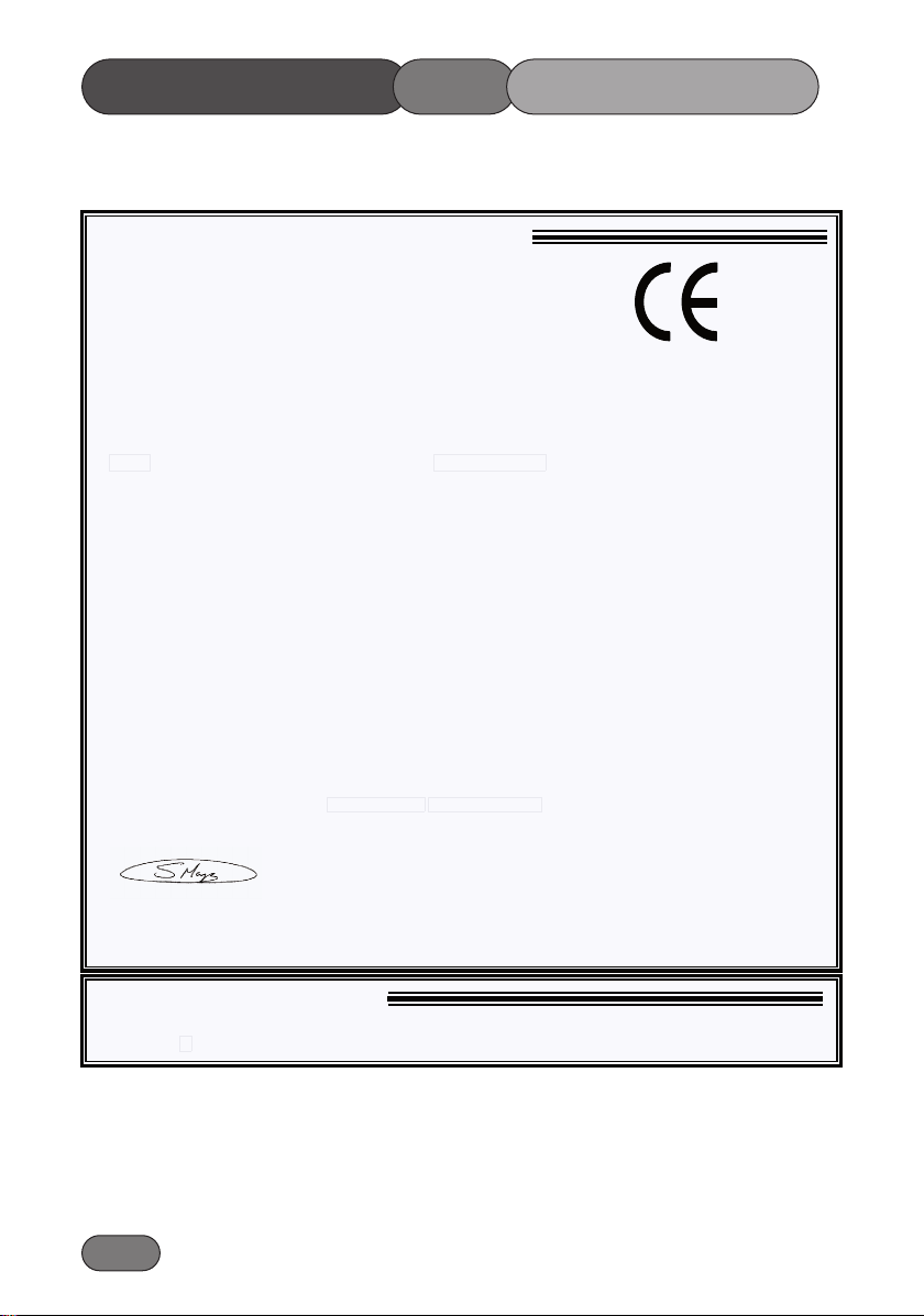
CONFORMITY
OFDECLARATION
EC DECLARATION OF CONFORMITY
Manufacturer: HAYTER LIMITED,
Address: Spellbrook, Bishop’s Stortford, Herts. CM23 4BU. ENGLAND
declare that the lawnmower:
Model name:
Type:
Model No :
Cutting width:
Speed of rotation of the cutting device:
Engine
manufacturer:
Speed of rotation of engine:
Complies with the provisions of Directive: 98/37/EC Essential Health & Safety Requirements Relating to the Design &
Construction of Machinery and Safety Components, as amendedand the regulations transposed into national law.
Also Directive 89/336/EEC Electromagnetic Compatibility, as amended and the regulations transposed into national law.
Also Directive 2000/14/EC Noise emission in the environment by equipment for use outdoors and the regulations transposed into
national law.
Procedure applied for the conformity assessm ent: ANNEX VI, procedure 1.
Notified Body: Sound Research Laboratories Ltd. Holbrook House, Little Waldingfield,
Sudbury, Suffolk. CO10 0TH. ENGLAND
Notified body identification No: 1088
Measured sound power level:
Guaranteed sound power level:
Complies with harmonized standards: EN 292, EN 836
Signed
S.A Maryniak
(Technical Director)
Harrier 48
BBC Autodrive V/S
Pedestrian Rotary
CODE 493F
48 cm
2750 rpm
Briggs and Stratton
2750 rpm
95 dB(A)
96 dB(A)
and EN ISO 14982
Date: March 2006
Declaration done and technical documentation kept at:
HAYTER LIMITED
Spellbrook, Bishop’s Stortford,
Herts. CM23 4BU ENGLAND
VIBRATION INFORMATION
The vibration level at the operator contact positions, measured in accordance with European Standard EN 836
CODE 493F - 5ms
-2
Page 35

Page 36

1.36
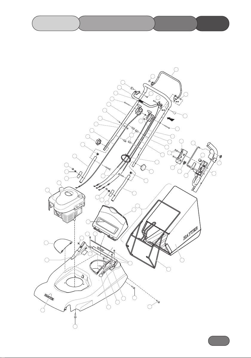
UPPER MAINFRAME
PARTS
LIST
Qty Item Note
1 GRIP FIX EXT 5/16 04020 2
2 CONNECTING ROD 111-0187 1
3 BATTERY COVER 111-0595 1
4 BOLT HANDLEBAR M8*45 HY226024 2
5 CABLE BBC 111-0748 1
6 CABLE GUIDE 410037 4
7 CABLE_CLUTCH V/S 111-1548 1
8 CAP FOR M8 NUT BLACK HY234051 2
9 HANDLEBAR CLAMP PLATE 340028 2
10 MOULDING SECURING 111-1065 1
11 DEFLECTOR 111-1714 1
12 ENGINE XTS50 B&S 111-0204 1
13 BBC CONTROL LEVER 340179 1
14 FRAME_GRASSBAG 111-1497-03 1
15 GRASSBAG 111-1715 1
16 GUIDE_ROPE 305093 1
17 HANDLEBAR LOWER 111-1913-03 2
18 HANDLEBAR UPPER MOULDED 111-0519 1
19 LEVER CLUTCH 111-1921-03 1
20 BOLT COACH M8 x 45 09379 2
21 NUT M6 NYLOC ‘T’ TYPE 09438 2
22 NUT M8 NYL INSERT T TYPE 09441 2
23 PIN PIVOT 340182 2
24 RATCHET PLATE HOC 111-0201 1
25 CONTROL LEVER MOULDING 111-0185 1
26 ROD DEFLECTOR 560017 1
27 SCREW TAPTITE M6*16 09365 4
28 TOP MOULDING CONTROL 111-0183 1
29 SCREW TAPTITE UNC 3/8"*1 1/4" 09349 1
30 SCREW 06*20 PT PAN FLANGE 09687 2
31 SETSCREW M6x55 POSI PAN Z&P 09780 2
32 THROTTLE CONTROL BBC 111-0747 1
33 SPRING DEFLECTOR 410030 1
34 CABLE VARIATOR 111-1193 1
35 KNOB M8 HANDWHEEL 480088 2
36 WASHER NYLON 19*11*1.6 09688 2
37 ACTUATOR MOULDING CONTROL 111-0186 1
38 ANCHOR MOULDING CONTROL 111-0184 1
39 PLUG TUBE 7/8*15G 300160 2
40 DECAL HAYTER ROYAL WARRANT 410087 1
41 DECAL SERIAL NUMBER -------- 1
42 DECAL ENGINE HARRIER 48 111-0759 1
43 STARLOCK PUSH-ON FASTENER 5MM 111-0718 1
44 CABLE TIE HY3966 1
45 DECAL HEIGHT OF CUT 320006 1
46 KIT GRASSBAG ASSEMBLY 111-1551 1
INCLUDES 14,15
Not shown
47 DECAL BBC 111-0745 1
48 WASHER PLAIN M6*12*1.6 09472 1
49 DECAL CAUTION 111-0083 1
50 NUT M6 NYLOC P TYPE 09544 1
51 BASE MOULDING CONTROL 111-0182 1
52 SCREW 10*3/4 S.TAP 70-11-012 3
Page 37
LISTPARTS
MAINFRAMEUPPER
1.37
19
36
23
13
47
31
18
16
48
50
32
35
39
17
8
22
9
42
12
4
*
8
22
9
6
30
30
21
44
35
39
17
46
11
A
31
21
25
7
5
52
34
28
10
View A
36
23
2
38
43
37
51
49
26
27
3
41
40
1
*
33
27
20
1
24
45
29
20
15
14
Page 38

1.38
Item No. Description Part No. Qty Item Note
1 FRONT AXLE WELD ASSY 111-0588 1
2 BAR SPRING TENSION 111-0672 1
3 BEARING 6001-2RS 111-1276 2
4 BEARING FRONT AXLE 410069 2
5 BEARING HOUSING ROLLER 111-1492 2
6 BELT VARIATOR 536 111-0771 1
7 BOLT CENTRE BBC 343029 1
8 BRACKET CABLE HY412003 1
9 BRACKET CONN ROD 111-0699 1
10 DUST COVER PLATE 111-1861 1
11 BUSH PIVOT 411031 1
12 PULLEY 51MM PCD 111-0822 1
13 CHAIN 40 PITCHES 3/8" INC LINK" 411016 1
14 SUPPORT BRACKET REAR ROLLER 111-1807 1
15 ROD-CONNECTING 111-0202 1
16 COVER DRIVE 411013 1
17 CUTTERBAR BBC 485005 1
18 SPRING CABLE ANCHOR 111-0527 1
19 ROLLER FREEWHEEL ROCKET BRAND 340150 2
20 WARNER BBC 5915-24 485007 1
21 FRONT_FINS 111-0594 1
22 GEARBOX 111-1273 1
23 GRIP FIX EXT 5/16" 04020 1
24 HOUSING PIVOT BEARING - LH 410048 2
25 CAP HUB 111-1251 2
26 KEY WOODRUFF No 505 1662 1
27 KNOB HOC 480134 1
28 LEVER HOC 480128 1
29 LEVER VARIABLE PULLEY 111-1480 1
30 LOCKNUT 340163 1
31 NUT M6 LUG 410076 4
32 MAINFRAME 111-1650-08 1
33 NUT M6 NYLOC 'P' TYPE 09544 2
34 NUT M8 NYL INSERT T TYPE 09441 1
35 NUT UNF 1/2" NYLOC EXT THIN5/16" HY4486 2
36 SPACER 340157 1
37 OILITE BUSH ROLLER 340129 2
38 PIN ROLL DIA 3/16*3/4 03997 1
39 PIN SELLOC SPRING 3/16*1 HD HY03354 1
40 PLATE SECURING 219037 1
41 FRAME REAR ROLLER W/A 111-1187-03 1
42 ROLLER SHELL ASSEMBLY 111-0592-03 2
43 SPRING BLADE BRAKE TENSION 343011 1
44 SCREW TAPTITE M6*16 09365 26
45 SCREW TAPTITE M6*16 C/SK POZI 09545 4
46 SCREW TAPTITE M6*20 W/HD 09575 9
47 SCREW TAPTITE M8*25 HEX W/HD 09787 1
48 SETSCREW M6*25 09364 2
49 SHAFT ROLLER WELDED 111-1727 1
50 SHROUD-FREEWHEEL 340168 1
51 SPRING COUNTER BALANCE 410050 1
52 SPRING TORSION HOC GALV 480132 1
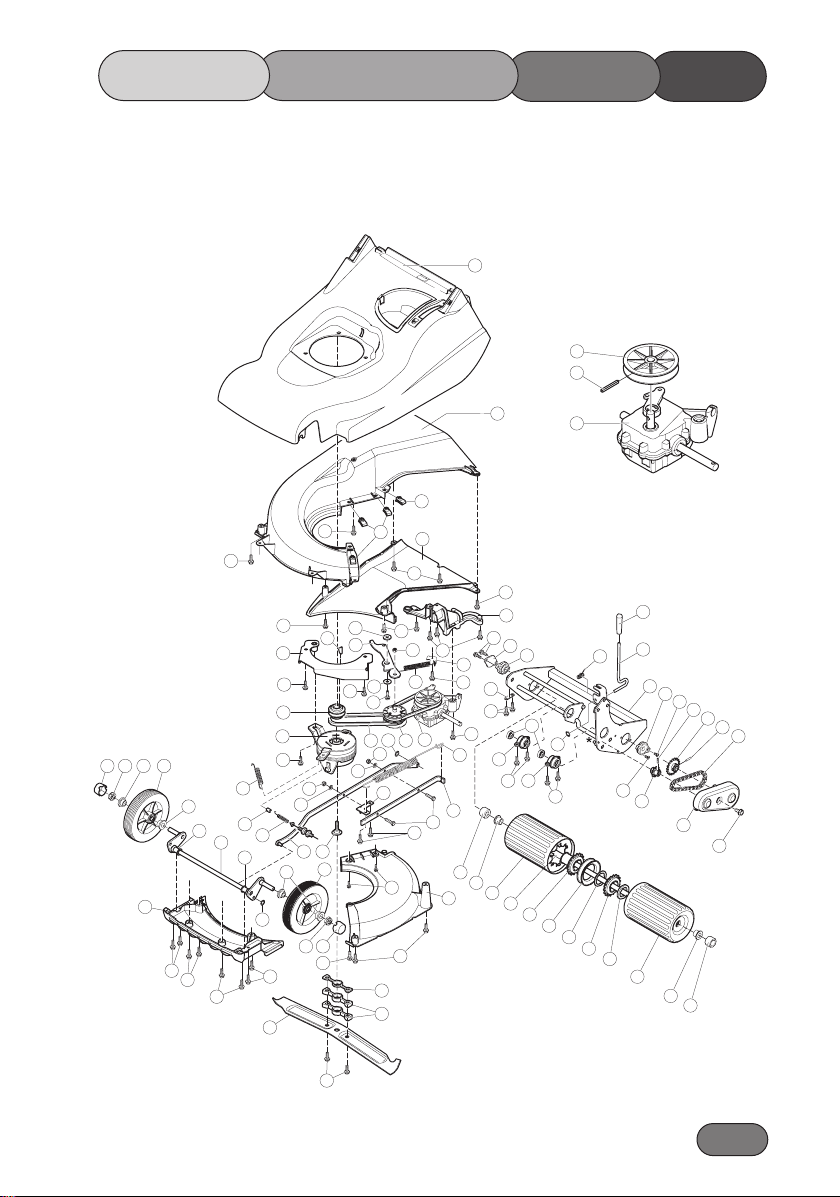
LOWER MAINFRAME
PARTS
LIST
Page 39
1.39
LISTPARTS
MAINFRAMELOWER
32
68
69
67
25 64
35
21
57
31
44
31
56
44
**
**
44
26
71
74
12
20
62
43
67
75
4
**
18
1
4
67
74
33
61
7
15
64
**
63
25
35
44
44
44
46
44
17
44
11
46
29
34
44
53
60
47
A
70
63
59
6
33
61
*
9
48
44
46
44
66
73
44
14
44
10
8
44
40
44
46
51
24
46
2
65
37
42
58
49
22
Detail A
27
5
3
23
24
44
19
50
36
28
52
41
5
45
38
55
39
13
45
54
16
46
19
30
42
37
65
72
Page 40

1.40
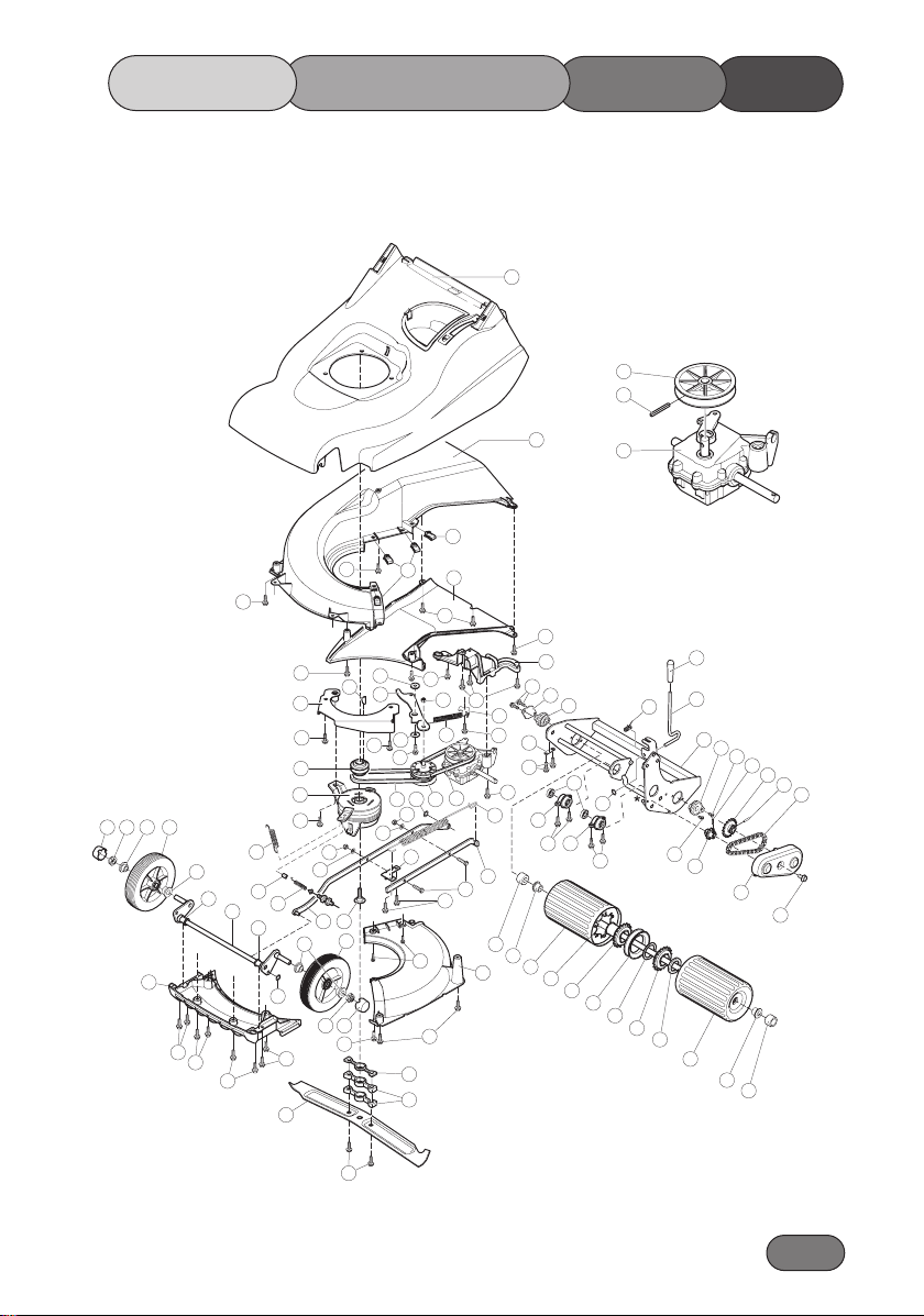
LOWER MAINFRAME
PARTS
LIST
Item No. Description Part No. Qty Item Note
53 SPRING VARIATOR HY412004 1
54 SPROCKET GEARBOX 10T*3/8 411011 1
55 SPROCKET ROLLER 18T*3/8 111-1552 1
56 THROWPLATE 111-0218 1
57 UNDERDECK CHUTE 111-0131 1
58 UNDERDECK COVER 111-0133 1
59 PULLEY VARIATOR ASSY 411001 1
60 WASHER PLAIN 5/16*1*16G 09270 1
61 WASHER PLAIN M6 09472 2
62 SCREW SOC SHOULDERED ZIS8L030S 1
63 WASHER STARLOCK 5/16" 0201086 2
64 WHEEL WITH BEARINGS 111-1250 2
65 DUST COVER BUSH 111-1860 2
66 SPACER CUTTERBAR BBC 111-0819 1
67 BEARING 111-1252 4 2 PER WHEEL
68 PULLEY 411019 1
69 PIN 411023 1
70 BELT VARIATOR 450 411025 1
71 BRACKET BBC W/A 111-0180-03 1
72 SCREW SOC. HD BUTTON 111-0820 2
73 SPACER CUTTERBAR BBC 111-0707 2
74 SCREW TAPTITE UNC 3/8*1 1/4 09349 2
75 NIPPLE SPLIT 510118 1
76 KIT STANDARD ROLLER SHAFT H48 111-1924 1
INCLUDES
19,30,36,39,49,50
Not shown
77 KIT REAR ROLLER H48 111-1925 1
5,10,13,16,19,23,27,2
8,30,36,37,39,41,42,4
4,45,46,48,49,50,52,5
5,63,65,Not shown
Page 41
1.41
LISTPARTS
MAINFRAMELOWER
32
68
69
67
25 64
35
21
57
31
44
31
56
44
**
**
44
26
71
74
12
20
62
43
67
75
4
**
18
1
4
67
74
33
61
7
15
64
**
63
25
35
44
44
44
46
44
17
44
11
46
29
34
44
53
60
47
A
70
63
59
6
33
61
*
9
48
44
46
44
66
73
44
14
44
10
8
44
40
44
46
51
24
46
2
65
37
42
58
49
22
Detail A
27
5
3
23
24
44
19
50
36
28
52
41
5
45
38
55
39
13
45
54
16
46
19
30
42
37
65
72
Page 42

1.42
NOTES
Page 43

1.43
NOTES
Page 44
1.44
Serial No:
Engine Type:-
Series 650 (493F) Engine:- Briggs & Stratton
Date of Sale:-
Your Local Dealer:-
Notes:-
CUSTOMER INFORMATION /NOTES
 Loading...