

Page 1

POWERTRIM
Code 407D
OWNER’S HANDBOOK
FROM SERIAL NO:407D001001 PART NO: 111-0443 (rev.0.)
ISSUE: 01-20-06
Page 2

TABLE OF CONTENTS
OWNER’S INFORMATION 4
SAFETY PRECAUTIONS 4
INTERNATIONAL PICTORIALS 7
ASSEMBLY 8
OPERATION 11
MAINTENANCE 14
TROUBLE SHOOTING CHART 20
REPAIR PARTS 22
Declared vibration emission values in accordance with Directive 98/37/EC.
Vibration Emission according to EN 836/A2:2001: 10 m/s2.
Values determined at the handle when the machine was operated stationary on a
concrete surface at 3600 min-1.
Declared Airborne Sound Power level of 106 dB(A) is in accordance with
Directive 2000/14/EC.
Sound Pressure Level at operator position 90 dB.
Values determined at ear according to the specifications of EN 836/A2:2001.
276798MA DRAFT COPY
2
Page 3

LIMITED WARRANTY
Hayter Limited warrants to the original user / purchaser that this unit shall be free from defects in
material and workmanship under normal use and service for a period of three years from the
date of purchase. The manufacturers of the engine and battery pack system (where applicable)
furnish their own warranty and services are provided through their authorised network (Refer to
“Engine/Battery Pack Warranty Statement”). To qualify for the full benefit of the warranty, the warranty registration card must be returned within 60 days of purchase. Subject to the conditions and
exclusions noted in this limited warranty, we shall at our option, repair or replace any warranted
part during the applicable period. If you are in doubt or experience any difficulty, please consult a
Hayter Authorised Service Dealer for clarification..
To qualify for the extended warranty (second and third year) of the three year limited warranty, the
machine must have annual services carried out by an Authorised Hayter Service Dealer. These
chargeable services should be carried out within 12 and 24 months of the date of purchase.
Excluded from the extended warranty period are those items which are subject to normal wear
and tear e.g. tyres, wheels, cutterbars, cables, batteries and other consumable wearing parts.
All consumer machines which are fitted with a genuine Hayter friction disc as original equipment,
before use, are covered by a Lifetime Warranty against the engine crankshaft bending. Note:
friction washers, blade brake units and other such devices are not applicable. Only machines
fitted with a genuine Hayter friction disc, which are used in accordance with the recommended
operating and maintenance procedures, are covered.
This warranty does not apply to any unit that has been tampered with, altered, misused, abused
or used for hire, and will become invalid if non genuine Hayter parts are fitted. This warranty does
not cover minor mechanical adjustments unless they are due to defective materials or workmanship. Consult the Owner’s Handbook or a Hayter Authorised Service Dealer for assistance when
making these adjustments.
A warranty period of 90 days applies to machines used for commercial purposes.
To make a warranty claim, return the unit to a Hayter authorised dealer along with proof of purchase stating the machine serial number and date of purchase. The service receipt(s) or this
Owner’s Handbook with the 1st/2nd year service boxes fully completed, must be produced as
proof of entitlement to the extended warranty period. Subject to the conditions and exclusions in
this limited warranty, the authorised dealer will, at our option, repair or replace any warranted part
within the duration of the warranty period.
This limited warranty gives you specific legal rights and is in addition to any statutory rights to
which you may be entitled and your statutory rights are not affected by this warranty. If you need
additional information concerning this written warranty, or assistance in obtaining services,
please write to:
HAYTER LIMITED,
Service Department,
Spellbrook,
Bishop’s Stortford,
Hertfordshire. CM23 4BU
1st Year
Service
Record
Date . . . . . . . . . .. . . . . . . . . . . . . . . . . . . . . . . .
Signed . . . . . . . . . . . . . . . . . . . . . . . . . . . . . . . .
276798MA DRAFT COPY
2nd Year
Service
Record
Date . . . . . . . . . .. . . . . . . . . . . . . . . . . . . . . . . .
Signed . . . . . . . . . . . . . . . . . . . . . . . . . . . . . . . .
3
Page 4

SAFETY RULES
s
OWNER’S INFORMATION
Know your product: If you understand the
unit and how the unit operates, you will get
the best performance. As you read this manual, compare the illustrations to the unit. Learn
the location and the function of the controls.
To help prevent an accident, follow the operating instructions and the safety rules. Keep
this manual for future reference.
WARNING: Look for this symbol to indicate important safety precautions. This
symbol indicates: “Attention! Become
Alert! Your Safety Is At Risk.”
Responsibility Of The Owner
WARNING: This cutting machine
is capable of throwing objects.
Failure to observe the following
safety instructions could result in seriou
injury to the operator or bystanders.
The responsibility of the owner is
to follow the instructions below.
SAFETY PRECAUTIONS
I. General Operation
1. Read, understand, and follow all instructions on the machine and in the manual(s). Be thoroughly familiar with the
controls and the proper use of the machine before starting.
2. Familiarise yourself with all of the safety
and operating decals on this equipment
and on any of its attachments or accessories.
3. Do not put hands or feet near or under
rotating parts.
4. Only allow responsible individuals, who
are familiar with the instructions, to operate the machine.
276798MA DRAFT COPY
5. Inspect the area where the machine is to
be used. Your equipment can propel
small objects at high speed causing personal injury or property damage. Stay
away from breakable objects, such as
windows, greenhouses, etc.
6. Keep the area of operation clear of all
persons, particularly small children, and
pets.
7. Wear appropriate clothing such as a
long−sleeved shirt or jacket. Also wear
long trousers. Do not wear shorts.
8. Do not wear loose clothing which could
get caught in this equipment.
9. Always wear safety goggles or safety
glasses with side shields when operating
the machine to protect your eyes from
foreign objects which can be thrown
from the unit.
10. Always wear work gloves and sturdy
footwear. Leather work shoes or short
boots work well for most people. These
will protect the operator’s ankles and
shins from small sticks, splinters, and
other debris, and improve traction.
11. It is advisable to wear protective headgear to prevent the possibility of being
struck by small flying particles, or being
struck by low hanging branches, twigs,
or other objects which may be unnoticed
by the operator.
12. Do not operate the machine without
proper guards or other safety protective
devices in place.
13. Use this equipment for its intended purpose only.
14. See manufacturer’s instructions for proper operation and installation of accessories. Only use accessories approved by
the manufacturer.
15. Operate only in daylight or good artificial
light.
16. Do not operate the machine while under
the influence of alcohol, drugs or other
medication which can cause drowsiness
or affect your ability to operate this machine safely.
17. Never operate machine in wet grass. Always be sure of your footing; keep a firm
hold on the handle and walk; never run.
4
Page 5

18. Before each use, inspect the throttle
SAFETY RULES
control lever and cable. Make sure that
the cable is free and that the lever is not
damaged. Also check the cable linkage
running to the carburetor for kinks, loose
fittings, and obstructions. Verify that the
control bail is working properly.
19. Stop the rotating trimmer head when
crossing gravel drives, walks, or roads.
Wait for the cutting lines to stop rotating.
20. Watch for traffic when operating near, or
when crossing roads.
21. Stop the engine whenever you leave the
equipment, before cleaning repairing or
inspecting the unit, be sure the trimmer
head and all moving parts have stopped.
Let the engine cool, disconnect the
spark plug wire and move it away from
the spark plug.
22. If the equipment should start to vibrate
abnormally, stop the engine, disconnect
the spark plug wire and prevent it from
touching the spark plug. Check immediately for the cause. Vibration is generally
a warning of trouble.
23. After striking a foreign object, stop the
engine. Remove the wire from the spark
plug. Inspect the machine for damage. If
damaged, repair before starting and operating the machine.
24. Never leave the machine unattended
when the engine is running. Remove
the wire from the spark plug.
25. Regularly inspect the machine. Make
sure parts are not bent, damaged or
loose.
26. Never pick up or carry the machine while
the engine is running.
27. Prolonged exposure to noise and vibration from petrol engine powered equipment should be avoided. Take
intermittant breaks and/or wear ear
protection from engine noise as well as
heavy work gloves to reduce vibration in
the hands.
II. Slope Operation
Slopes are a major factor related to slip and
fall accidents which can result in severe injury. All slopes require extra caution. If you feel
uneasy on a slope, do not trim it.
276798MA DRAFT COPY
Do trim across the face of slopes; never up
and down. Do not trim excessively steep
slopes (maximum 15 degrees) or areas
where the ground is very rough. Exercise extreme caution when changing direction on
slopes.
Do remove objects such as rocks, tree limbs,
etc.
Do watch for holes, ruts, or bumps. Tall grass
can hide obstacles.
Do not trim near drop−offs, ditches, or em-
bankments. The operator could lose footing
or balance.
Do not trim on wet grass. Reduced footing
could cause slipping.
III. Children
Tragic accidents can occur if the operator is
not alert to the presence of children. Children
are often attracted to the machine and the
trimming activity. Never assume that children
will remain where you last saw them.
1. Keep children out of the trimming area
and under the watchful care of a responsible adult.
2. Be alert and turn machine off if children
enter the area.
3. Before and while moving backwards,
look behind and down for small children.
4. Never allow children to operate the machine.
5. Use extra care when approaching blind
corners, shrubs, trees, or other objects
that may obscure vision.
IV. Service
1. Use extra care in handling petrol and
other fuels. They are flammable and vapors are explosive.
a. Use only an approved container.
b. Never remove gas cap or add fuel
with the engine running. Allow engine to cool before refueling. Do not
smoke.
c. Never refuel the machine indoors.
d. Never store the machine or fuel
container inside where there is an
open flame, such as a water heater.
e. If the fuel tank has to be drained,
this should be done outdoors. The
drained fuel should be stored in a
container specifically designed for
fuel storage or it should be dis-
5
posed of carefully.
Page 6

2. Never run an engine indoors or inside a
SAFETY RULES
closed area.
3. Never make adjustments or repairs with
the engine running. Disconnect the
spark plug wire, and keep the wire away
from the plug to prevent accidental starting. Always wear eye protection when
you make adjustments or repairs.
4. Check the trimmer head and engine
mounting bolts at frequent intervals for
proper tightness.
5. Keep all nuts and bolts tight and keep
equipment in good condition. Check
mounting hardware on trimmer head every time you change trimmer line and
prior to each use.
6. Never tamper with safety devices.
Check their proper operation regularly.
7. When servicing or repairing the machine, do not tip the machine over or up
unless specifically instructed to do so in
this Manual. Service and repair procedures can be done with the machine in
an upright position. Some procedures
will be easier if the machine is lifted on a
raised platform or working surface.
8. To reduce fire hazard, keep machine
free of grass, leaves, or other debris
build−up. Clean up oil or fuel spillage.
Allow machine to cool before storing.
9. Stop and inspect the equipment if you
strike an object. Repair, if necessary, before restarting.
10. Always disconnect spark plug wire before cleaning, repairing, or adjusting.
11. Do not change the engine governor setting or over−speed the engine.
12. Clean and replace safety and instruction
decals as necessary.
13. To guard against engine over−heating,
always have engine debris filter
mounted and clean.
14. Inspect machine before storage.
15. Use only original equipment or authorised replacement parts.
16. Never replace the cutting lines with metal parts.
276798MA DRAFT COPY
6
Page 7

SAFETY RULES
INTERNATIONAL PICTORIALS
IMPORTANT: The following pictorials are located on your unit or on literature supplied
with the product. Before you operate the unit, learn and understand the purpose for
each pictorial.
12
5
67
3
Safety Warning Pictorials
1 WARNING
2 IMPORTANT: Read Owner’s Manual
Before Operating This Machine.
3 WARNING: Thrown Objects. Keep
Bystanders Away. Read User
Instructions Before Operating This
Machine.
4 Do Not Trim Up And Down Slopes. Trim
Across Slopes.
1
2
4
8
5 WARNING: Rotating Parts. Stop Engine.
Disconnect Spark Plug Wire Before
Making Adjustments.
6 WARNING: Wear Eye Protection
7 DANGER: Disconnect Spark Plug Wire
Before Servicing Unit.
8 Direction of Rotating Line.
9 Declared airborne sound power level of
106dB(A) is in accordance with Directive
2000/14/EC.
3
9
4
5
6
Control And Operating Pictorials
1 Slow
2 Fast
3 Engine Stop
4 Engine Stop
276798MA DRAFT COPY
7
5 Oil
6 Fuel
7 Engage
8 Disengage
7
8
Page 8

ASSEMBLY
CONTENTS OF PARTS BAG
1 − Owner’s Manual
1 − Parts Bag
(Not shown actual size)
1 − Bag (4 Screws)
1 − Safety Glasses
ASSEMBLY
1 − 20 oz. Bottle Oil
2 Sets − Trimmer Lines
(0.155 inch diameter)
WARNING: Always wear safety
glasses or eye shields while assembling the machine.
TOOLS REQUIRED
1 − Knife to cut carton.
1 − T−Handle Wrench.
Figure 1 shows the machine completely assembled and positioned in the carton for shipment.
References to the right or left hand side of the
machine are from the viewpoint of the operator’s position behind the unit.
TO REMOVE THE
TRIMMER FROM CARTON
1. Remove the parts bag and any loose parts
from carton.
2. Remove the packing material positioned
around the unit.
3. Cut down all four corners of the carton and
lay the side panels flat.
4. Pull the trimmer out of the carton and off
the base pad.
5. Remove packing material from around the
trimmer head.
6. Remove protective plastic from front of
frame.
276798MA DRAFT COPY
Figure 1
8
Page 9
ASSEMBLY
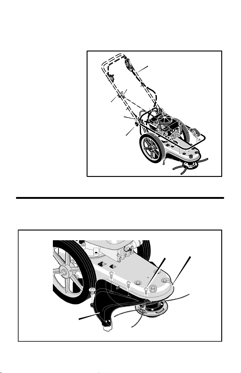
HOW TO RAISE THE HANDLE
1. Hold the handle with one hand and loosen both handle adjustment knobs until the ratchet
teeth are disengaged. Do not remove the handle adjustment knobs. See Figure 2.
2. Raise the handle to the
operating position.
3. Stand in the operator’s
position behind the machine. Put the handle in
a comfortable position.
Make sure both sides of
the handle are level.
NOTE: Make sure the
cables are not caught
between the upper and
lower handle.
4. Tighten the handle adjustment knobs. Make
sure the handle pivots
are locked in place.
NOTE: The handlebar
height is adjustable.
See “How To Adjust
The Height Of The Handlebar” in the Maintenance section.
5. To attach the recoil start handle to the rope guide, twist the rope through
the rope guide mounted on the right side of the handlebar.
Recoil Start
Handle
Handle Adjustment
Handle
Pivot
Knob
Rope
Guide
Handle
Figure 2
HOW TO ATTACH THE GUARD
1. Attach the guard to the machine with the
four fasteners as shown. See Figure 3.
Guard
276798MA DRAFT COPY
Fastener
9
Trimmer
Figure 3
Page 10

ASSEMBLY
ENGINE PREPARATION
Note: Engine does not contain OIL or
PETROL.
WARNING: Follow the engine
manufacturer’s instructions for
the type of petrol and oil to use.
Always use a safety petrol container. Do
not smoke when adding petrol to the engine. When inside an enclosure, do not
fill with petrol. Before you add petrol,
stop the engine. Let the engine cool for
several minutes.
See the engine manufacturer’s instructions
for the type of petrol and oil to use. Before
you use the unit, read the information on
safety, operation, maintenance, and storage.
Note: Actual sustained horsepower will
likely be lower due to operating limitations and environmental factors.
Fill Crankcase With Oil
1. Remove the oil fill cap/dipstick shown in
Figure 4. Fill the crankcase to the FULL
line on oil fill cap/dipstick. DO NOT OVER-
FILL.
2. Install the oil fill cap/dipstick and tighten
securely.
Fill Fuel Tank With Petrol
See the engine manufacturer’s instructions for
the type of petrol to use.
Oil Fill
Cap/Dipstick
Fuel
Cap
Figure 4
n CHECKLIST
For the best performance and satisfaction
from this quality product, please review the following checklist before you operate the machine:
n All assembly instructions have been
completed.
n Check carton. Make sure no loose parts
remain in the carton.
276798MA DRAFT COPY
As you learn how to use the machine, pay extra attention to the following important items:
nn Engine oil is at correct level.
nn Fuel tank is filled with fresh, clean, reg-
ular unleaded petrol.
nn Become familiar and understand the
function of all controls. Before your start
the engine, operate all controls.
10
Page 11

OPERATION
l
c
KNOW YOUR POWERTRIM
READ THE OWNER’S HANDBOOK AND ALL SAFETY RULES BEFORE YOU OPERATE the
machine. To familiarise yourself with the location of the controls, compare the illustrations with your
machine. Save this handbook for future reference.
Control Bail
Upper Handle
Throttle Control Lever
Recoil Starter Handle
Handle Adjustment Knob
Fuel Cap
Shield Edge Guard
Trimmer Head Drive Lever
Trimmer Head Drive Lever − Engages
the rotation of the trimmer head.
Control Bail − Release to stop the rotation
of the trimmer head.
Dipstick
Trimmer Head
Trimmer Line
Figure 5
Throttle Control Lever − Controls the
speed or stops the engine.
Recoil Starter Handle − The engine is
equipped with an easy pull recoil starter.
EYE PROTECTION
WARNING: Debris thrown from
the machine can result in
foreign objects being thrown
into the eyes, which can cause severe
eye damage. Always wear safety
glasses or eye shields when operating
the machine.
Always wear safety glasses. If you wear eye
glasses, put a Wide Vision Safety Mask over
your eye glasses.
276798MA DRAFT COPY
HOW TO STOP
THE TRIMMER HEAD
1. Release the control bail. It will return to its
open position and disengage the trimmer
head.
HOW TO STOP THE ENGINE
WARNING: The trimmer head wil
continue to rotate for several se
onds after the engine has
stopped
1. Move the throttle control lever completely back to the STOP position.
11
Page 12

OPERATION
HOW TO USE THE
TRIMMER HEAD DRIVE LEVER
1. To engage the trimmer head, hold the control bail against the handle. Move the
trimmer head drive lever forward to en-
gage the trimmer head. See Figure 6. The
faster the engine runs, the faster the trimmer head will rotate.
2. Once the trimmer head is rotating, push
the machine forward to trim.
HOW TO USE THE
THROTTLE CONTROL
1. During normal use, set the throttle control lever in the FAST position to run the
engine at full speed.
2. Pull the throttle control lever back to de-
crease engine speed. Push the throttle
control lever forward to increase engine
speed.
3. To stop the engine, pull the throttle con-
trol lever completely back to the STOP
position.
Control Bail
Handlebar
Trimmer Head
Drive Lever
Throttle Control
Figure 6
Lever
Figure 7
HOW TO USE
THE PRIMER BUTTON
1. Push the primer button. See Figure 8 for
location. For the number of times to push
the primer button, see the primer button
decal located on the engine or follow the
directions in the Engine Manual. Wait
approximately two seconds between each
push.
NOTE: Do not use the primer button to restart a warm engine after a short shutdown.
276798MA DRAFT COPY
12
Primer
Button
Figure 8
Page 13

OPERATION
HOW TO START THE ENGINE
NOTE: DO NOT BE ALARMED, your engine
will smoke the first time it is started. It is
burning off the protective coating that is on
the internal engine parts.
WARNING: Never leave the machine unattended while the engine is running. Wait for the trimmer lines to stop rotation.
1. Before each use, remove debris from the
debris screen shown in Figure 5. Debris
can cause the engine to overheat. Wipe
the debris screen with a cloth or paper
towel.
2. Move the throttle control lever forward to
the START or FAST position.
3. To start a cold engine, push the primer button five times. Wait two seconds between
each push of the primer button.
NOTE: Do not use the primer to start a
warm engine.
4. Firmly hold the recoil starter handle with
your right hand. See Figure 9.
5. Pull back sharply on the recoil starter
handle. DO NOT allow the starter rope to
snap back. Let the starter rope slowly rewind as you hold the recoil starter handle.
NOTE: If engine fails to start after three
pulls, push the primer button two times and
again pull the recoil starter handle.
WARNING: Never run the engine
indoors or in a poorly ventilated
area. Engine exhaust contains
carbon monoxide, an odorless
and deadly gas. Keep hands,
feet, hair and loose clothing
away from the machine and any
moving parts on the engine.
Avoid the muffler and surrounding areas. Temperatures may exceed 1505F.
Recoil Starter Handle
Figure 9
TRIMMER TIPS
WARNING: Debris such as sticks,
gravel or stones, can be thrown
with sufficient force to cause personal injury or property damage.
S Set the throttle control in the FAST posi-
tion. If the weeds or grass are tall and
thick, operate the machine at a slower
walking speed.
S Frequently clean the underside of the ma-
chine to remove any grass build up.
S For best results and longer lasting line,
use the ends of the line to do the cutting.
This is easily done by moving slowly
through very thick or heavy weeds.
S If the trimmer lines become too short, it will
276798MA DRAFT COPY
take longer to complete the job. If the trimmer lines are worn to less than half their
original length, change to a new trimmer
line. “See How To Change The Trimmer
Line” in the Maintenance section.
S Do not trim on excessively steep slopes. If
a slope is difficult to stand on, do not trim.
Do not trim on slopes when the ground is
slippery or wet. Trim across the face of a
slope, not up and down.
SSTrimming may be done at slower engine
speeds especially when trimming around
flowers, shrubs, and small trees. Operating at slower speeds will also reduce engine noise and vibration at the upper
handle.
13
Page 14

MAINTENANCE
CUSTOMER RESPONSIBILITIES
SERVICE RECORDS
Fill in dates as you
complete regular service.
Before
Each
Use
Every
5
Hours
Every
25
Hours
Every
100
Hours
As
Noted
SERVICE
DATES
Check Engine Oil Level
Check trimmer Lines
Check Trimmer Head
Engagement
Engine/Machine Cleaning
Check Nuts and Bolts
Check Spark Plug
Change Engine Oil
Service Air Filter
Lubricate Jackshaft Assembly
Lubricate Wheel Bearings
Note 1 − When old line is half the original length, replace with new line.
Note 2 − Clean daily if used in extremely dusty or dirty conditions.
Note 3 − Change more often if used in extremely dusty or dirty conditions.
√
√
√
√
√
√
√
√
√
√
PRODUCT SPECIFICATIONS
Trimmer Line Diameter 3.3mm (0.130”)
Trimmer Line Length 52omm (21.5”)
Height Of Cut (Fixed) 76mmm (3”)
Dimensions 1400 x 555 x 1000
Engine Briggs 122H02−0134−B1
Horse Power 6
Displacement 11.5 cu. in.
Petrol Capacity 1.5 litre (1.6 quarts)
Oil Capacity 0.6 litre (20 oz.)
Spark Plug Champion RJ−19LM
Spark Plug Gap 0.030”
Weight 29.5kg
276798MA DRAFT COPY
14
1
2
3
Page 15

LUBRICATION
MAINTENANCE
How To Lubricate
The Jackshaft Assembly
A grease fitting is provided to lubricate the
jackshaft assembly. Use a grease gun with automotive type grease to lubricate the jackshaft
assembly as shown in Figure 10.
How To Change Engine Oil
Change the engine oil when the engine is
warm. For the proper oil capacity, see the engine manufacturer’s instructions.
1. Disconnect spark plug wire from the spark
plug.
2. Remove the oil drain plug as shown in
Figure 11.
3. Drain all the engine oil into a flat pan.
4. Install the oil drain plug. Make sure the
oil drain plug is tight.
5. Remove the dipstick.
6. Fill the engine crankcase. DO NOT
OVERFILL. For proper oil capacity, see
the engine manufacturer’s instructions.
Grease Fitting
Figure 10
7. Connect the spark plug wire to the spark
plug.
Oil Drain Plug
Figure 11
276798MA DRAFT COPY
15
Page 16

MAINTENANCE
SPARK PLUG
Check the spark plug every 25 hours. Replace the spark plug if the electrodes are
pitted or burned or if the porcelain is cracked.
1. Make sure the spark plug is clean. Clean
the spark plug by carefully scraping the
electrodes (do not sand blast or use a wire
brush).
2. Check the spark plug gap with a feeler
gauge. See “Product Specifications” for
the correct spark plug gap and replace-
ment spark plug.
3. Before installing the spark plug, coat the
threads lightly with oil for easy removal.
Tighten the spark plug to a torque of 15
foot−pounds.
Feeler Gauge
0.030”
Spark Plug
Figure 12
HOW TO ADJUST THE HEIGHT OF
THE HANDLEBAR
Use the knobs, on each side of the handlebar, to adjust the height of the handlebar.
1. Hold the handlebar with one hand and
loosen both knobs until the ratchet teeth
are disengaged. Do not remove the
knobs. See Figure 13.
2. Move the handlebar up or down to the de-
sired position, then align the ratchet
teeth. Make sure both sides of the handlebar are level.
3. Tighten the knobs.
276798MA DRAFT COPY
16
Handlebar
Knob
Ratchet
Teeth
Figure 13
Page 17

MAINTENANCE
SERVICE AND ADJUSTMENT
WARNING: Before you inspect, clean or service the machine, stop the engine.
Make sure that all moving parts have stopped. Disconnect the wire from the
spark plug.
HOW TO REPLACE THE TRIMMER LINE
For the best performance, use a heavy
gauge 3.3mm (0.130” diameter) trimmer
line. Cut the length of the trimmer line to
52cm (21.5 inches). Do not allow the length
of the lines to vary more than one inch. This
is important to make sure the trimmer head
is balanced and does not vibrate.
HOW TO CHANGE TRIMMER LINES
When the trimmer line becomes worn to half the original length, replace the trimmer line as
follows:
IMPORTANT: To extend the life of the trimmer line, keep the trimmer line moist. If not
kept moist, the nylon trimmer line will become dry and brittle. Keep extra trimmer
line in a can of water. The line will then stay
flexible and easy to change. A flexible line
will also last much longer.
Line
Retainer
1. Stop the engine. Wait for
all moving parts to stop.
2. Remove worn trimmer
line from line retainer.
3. First, thread the ends of
the new trimmer line
through the outside
loops.
276798MA DRAFT COPY
Trimmer
Line
Line
Retainer
4. Next, take the ends of the
line, cross over the line
retainer, and thread the
ends through the centre
hole.
17
5. Then, check to make
sure that the ends of the
line are even.
Page 18

MAINTENANCE
HOW TO
REPLACE THE DRIVE BELT
To replace the drive belt, the trimmer head
and shield must be removed as follows.
WARNING: Before you remove
the drive belt, disconnect the
wire from the spark plug.
1. Remove the two fasteners that hold the
rear of the shield to the trimmer housing
(See Figure 14).
2. Remove the four fasteners that hold the
front of the shield and trimmer head to
the trimmer housing.
3. Remove the “V” pulley from the idler
bracket.
4. Raise the front of the trimmer housing
and remove the drive belt. On some models, it is necessary to loosen the mount-
ing bolt for the drive pulley to remove the
drive belt (see Figure 15). Do not bend the
belt guides.
NOTE: Make sure you replace the drive
belt only with a replacement belt from
the factory.
5. To assemble the drive belt, reverse the
above steps. Make sure all fasteners are
tight. Make sure the mounting bolt for the
drive pulley is tight.
6. Check the routing of the drive belt. Make
sure the drive belt is inside of all belt
guides shown in Figure 15.
IMPORTANT: Test the drive system. Start
the engine and move the throttle control to
the FAST position. Engage and disengage
the trimmer head several times. When disengaged, make sure the trimmer head completely stops when resting on the ground. If
the trimmer head continues to rotate, take
the machine to the nearest authorised
Service Dealer.
Drive Belt
Shield
Trimmer Head
Drive Belt
Belt Guide
Trimmer Housing
Drive Pulley
Figure 14
“V” Pulley
Belt Guide
Belt Guide
Mounting Bolt
Figure 15
276798MA DRAFT COPY
18
Page 19

MAINTENANCE
STORAGE
WARNING: Do not remove petrol
while inside a building, near a
fire, or while you smoke. Petrol
fumes can cause an explosion or
a fire.
When the machine is put in storage for thirty
days or more, follow the steps below to
make sure the machine is in good condition
the following season.
Trimmer
S Completely clean the machine.
S Put the machine in a building that has
good ventilation.
Engine
To prevent engine damage when the machine is in storage for 30 days or more, follow the steps below:
S Let the engine run until it is out of petrol.
S Drain the oil from the warm engine. Fill the
engine crankcase with new oil.
S Remove the spark plug from the cylinder.
Pour one ounce of oil into the cylinder.
Slowly pull the recoil starter handle so that
the oil will protect the cylinder. Install a new
spark plug in the cylinder.
S Clean dirt and debris from the cylinder
cooling fins and the engine housing.
276798MA DRAFT COPY
19
Page 20

TROUBLE SHOOTING CHART
TROUBLE CAUSE CORRECTION
Engine does not start Spark plug wire
disconnected.
Engine not primed. Prime engine.
Defective or incorrectly
gapped spark plug.
Fuel tank empty. Add fuel.
Dirty carburetor or fuel line. Clean carburetor or fuel line.
Dirty air filter. Replace air filter.
Carburetor out of adjustment. For carburetor adjustment,
Engine flooded. Wait several minutes before
Throttle control lever in
incorrect position.
Stale petrol. Drain old petrol and add
Defective throttle control
lever or wire.
Engine runs poorly. Bad spark plug. Replace spark plug.
Connect spark plug wire.
Inspect or replace spark
plug.
take the unit to an authorised
Service Dealer.
starting.
Move throttle lever to FAST
or START position.
fresh petrol.
Inspect lever and wire.
Replace if damaged or
defective.
276798MA DRAFT COPY
Dirty air filter. Replace air filter.
Carburetor out of adjustment. Adjust carburetor. Take the
Stale petrol. Drain old petrol. Add fresh
Engine cooling system
clogged.
20
unit to an authorised Service
Dealer.
petrol.
Clean engine screen and
cooling fins.
Page 21

TROUBLE SHOOTING CHART
Engine overheats. Engine cooling system
clogged.
Clean debris screen and
engine cooling fins.
Carburetor out of adjustment. Adjust carburetor. Take the
Oil level is low. Add oil.
Engine will not stop
running.
Poor trimming
performance.
Trimmer vibrates Trimmer line lengths are
Trimmer head does not
retain line
Defective throttle control
lever or wire.
Throttle not adjusted
properly.
Trimmer line length is too
short.
Engine not set at FAST
speed.
substantially different.
Loose nuts or bolts. Check all bolts and nuts,
Broken trimmer head. Replace broken part.
Trimmer line not properly
attached.
unit to an authorised Service
Dealer.
Inspect and replace
damaged parts.
Move throttle to the full OFF
position.
Correct line length is 52cm
(21.5 inches). When less
than 1/2 this length, replace
the line.
Move engine throttle lever to
FAST position.
Adjust trimmer line to
approximately equal lengths.
including engine bolts.
Follow instructions on decal
or in the Maintenance
section of the owner’s
handbook.
276798MA DRAFT COPY
Broken line retainer. Replace trimmer head
assembly.
Trimmer line not correct size. Use 3,3mm (0.130 inch)
diameter trimmer line.
21
Page 22

Code 407D REPAIR PARTS
34
1
2
13
3
6
2
7
8
6
9
4
11
4
10
12
31
4
11
28
33
32
5
9
10
16
17
20
19
18
14
15
16
18
17
276798MA DRAFT COPY
14
19
26
27
21
22
30
23
24
25
20
6
22
29
Page 23

Code 407D REPAIR PARTS
Key
No. Part No. Description
1 MU740198E549 Lever, Stop
2 MU323035 Bolt
3 MU740193 Cable, Control Latching
4 MU071372 Tie, Cable
5 MU740196E701 Handlebar
6 MU15x116 Nut
7 MU1601039 Control, Throttle
8 MU672510 Guide, Rope
9 MU740202 Knob, Handlebar
10 MU783000 Washer
11 MU711936 Washer, Spring
12 MU711937 Bolt
13 MU672292 Spacer
14 MU740158 Pivot, Handlebar
15 MU740195E701 Handlebar, Lower
16 MU740185 Wheel & Tire
17 MU015x84 Nut, Axle
18 MU0020x3 Washer
19 MU740190 Spacer
20 MU740188 Assembly, Axle & Bracket
21 MU26x274 Screw
22 MU711935 Bolt, Carriage
23 MU740150E549 Deck
24 MU0025x6 Bolt
25 MU740192 Shield, Trailing
26 MU001x45 Bolt
27 MU26x267 Screw
28 −−−−− Engine
29 MU711890 Protection, Eye
30 MU015x88 Nut
31 MU1601040 Support, Handle
32 MU26x268 Screw
33 MU042294 Clamp, Throttle
34 MU712409 Decal, Engine Stop
−− MU713004 Decal, Powertrim (not shown)
−− MU712416 Decal, Hayter (not shown)
−− MU713006 Decal, Warning (not shown)
−− MU276798MA Instruction Book & Parts List
276798MA DRAFT COPY
23
Page 24

Code 407D REPAIR PARTS
1
2
3
27
31
26
33
25
24
29
31
30
15
17
18
4
20
19
5
22
7
14
13
23
6
16
1
8
9
10
11
12
276798MA DRAFT COPY
24
Page 25

Code 407D REPAIR PARTS
Key
No. Part No. Description
1 MU015x84 Nut
2 MU025x11 Screw
3 MU740150E549 Frame, Trimmer
4 MU26x256 Screw
5 MU740231 Z Bracket, Idler Assembly
6 MU009x48 Bolt
7 MU712403 Spring
8 MU740292 Spacer
9 MU15x119 Nut
10 MU17x104 Washer
11 MU740171 Pulley, Cutting Head
12 MU740173 Spacer
13 MU711933 Belt
14 MU740244 Pulley, Idler
15 MU740179 Pulley, Engine
16 MU740183 Pulley, Idler
17 MU018x31 Lockwasher
18 MU001x20 Bolt
19 MU26x235 Screw
20 MU770070 Guard Assembly
22 MU740206 Guard
23 MU26x294 Screw
24 MU1001049 Jackshaft Housing Assembly
25 MU740300 Shaft, Cutting
26 MU740163 Wrap, Upper Head
27 MU712126 Screw
29 MU740175E549 Assembly, Cutting Disc
30 MU712127 Screw, Set
31 MU740164 Line, Cutting
33 MU740299 Guide Assembly, Metal Height
276798MA DRAFT COPY
25
Page 26

NOTES
276798MA DRAFT COPY
26
Page 27

NOTES
276798MA DRAFT COPY
27
Page 28

How To Order Replacement Parts
Use only manufacturer’s authorised or approved replacement parts. The letter
placed on the end of the part number denotes the type of finish for the part, C for
chrome, Z for zinc, a PA for purchased assembly. It is important that you include
this when ordering a part. Do not use attachments or accessories not specifically
recommended for this unit. In order to obtain proper replacement parts you must
supply the model number of your machine (see serial number).
Replacement parts, except for the engine, transmission, transaxle or differential,
are available from your local Hayter authorised dealer, the store where the
mower was purchased or a service shop recommended by the store.
If you are unable to obtain parts or service in the manner outlined above, then
contact:
HAYTER LIMITED,
Service Department,
Spellbrook,
Bishop’s Stortford,
Hertfordshire. CM23 4BU
When ordering the following information is required:
(1) The Model Number
(2) Serial Number
(3) Part Number
(4) Quantity
276798MA DRAFT COPY
28
 Loading...