

Hayter 13/40 144S Instruction Book

13/40
HERITAGE TRACTOR
CODE144S
INSTRUCTION BOOK
FROM SERIAL NO:144S001002 MANUAL PART NO:144002 (REV.0.)
F–000786J
5 (0011x3)
1
2
4 (711758)
6
3
3
2
1
2
1
3
4 (711644)
1 (711719)
1
2
5 (711747)
4
2 (711663)
3
3
5
6
7
5
6 (711636)
7 (711680)
3
10
2
9
8
7
5
6
6
4
1
2
F–000786J
11
1
2
10
11
7
7
3
1
8
2
12
5
9
10
6
9
1
2
12
6
5
8
3
7
7
1
2
8
3
4
10
6
5
1
2
F–000786J
11
12
1
2
3
3
4
5
3
2
13
1
2
3
14
15
12
4
5
2
11
10
8
1
9
3
F–000786J
4
16
17
1
1
2
3
2
19
2
18
20
1
F–000786J
3
1
4
5
21
1
2
22
3
2
1
3
4
4
1
24
3
2
23
25
2
1
F–000786J
1
2
6
26
2
1
27 28
1
3 (711909)
2
4 (711632)
29
711653
3
711653
30
5
6
1
F–000786J
6
5
7 (711741)
7
31
3
4
32
1
33
34
2
1
35
F–000786J
1
2
8
36
J
8
4
2
1
A
2
1
4
5
6
E
B
3
11
C
F
3
9
D
F–000786J
10
H
9
37
12 3 5467
9
16 18
10
17
1211 13
14 15
8
38
12 3456 78 9
10 11 12 13 14 15
0011x3
711758
711719
711663
711644
711680
39
327350
711747
711636
711909
F–000786J
711653
10
711632
711741

LIMITED WARRANTY
Hayter Limited warrants to the original user / purchaser that this unit shall be free from defects in material and
workmanship under normal use and service for a period of three years from the date of purchase. The manufacturers of the engine and battery pack system (where applicable) furnish their own warranty and services are provided through their authorised network (Refer to “Engine/Battery Pack Warranty Statement”). To qualify for the
full benefit of the warranty , the warranty registration card must be returned within 60 days of purchase. Subject to
the conditions and exclusions noted in this limited warranty, we shall at our option, repair or replace any warranted part during the applicable period. If you are in doubt or experience any difficulty, please consult a Hayter
Authorised Service Dealer for clarification..
To qualify for the extended warranty (second and third year) of the three year limited warranty , the machine must
have annual services carried out by an Authorised Hayter Service Dealer. These chargeable services should be
carried out within 12 and 24 months of the date of purchase.
Excluded from the extended warranty period are those items which are subject to normal wear and tear e.g. tyres,
wheels, cutterbars, cables, batteries and other consumable wearing parts.
All consumer machines which are fitted with a genuine Hayter friction disc as original equipment, before use, are
covered by a Lifetime Warranty against the engine crankshaft bending. Note: friction washers, blade brake
units and other such devices are not applicable. Only machines fitted with a genuine Hayter friction disc, which
are used in accordance with the recommended operating and maintenance procedures, are covered.
This warranty does not apply to any unit that has been tampered with, altered, misused, abused or used for hire,
and will become invalid if non genuine Hayter parts are fitted. This warranty does not cover minor mechanical
adjustments unless they are due to defective materials or workmanship. Consult the Owner’s Handbook or a
Hayter Authorised Service Dealer for assistance when making these adjustments.
A warranty period of 90 days applies to machines used for commercial purposes.
To make a warranty claim, return the unit to a Hayter authorised dealer along with proof of purchase stating the
machine serial number and date of purchase. The service receipt(s) or this Owner’s Handbook with the 1st/2nd
year service boxes fully completed, must be produced as proof of entitlement to the extended warranty period.
Subject to the conditions and exclusions in this limited warranty , the authorised dealer will, at our option, repair or
replace any warranted part within the duration of the warranty period.
This limited warranty gives you specific legal rights and is in addition to any statutory rights to which you may be
entitled and your statutory rights are not affected by this warranty. If you need additional information concerning
this written warranty, or assistance in obtaining services, please write to:
HAYTER LIMITED, Service Department, Spellbrook, Bishop’s Stortford, Hertfordshire. CM23 4BU.
GB
F–000786J
UK ONLY: Details of your local Hayter authorised dealer are contained in Y ellow Pages or contact: Freephone 0800 616298.
1st
Year
Service
Record
Date . . . . . . . . . . . . . . . . . . . . . . . . . . . . . . . . . . . . . . . . .
Signed . . . . . . . . . . . . . . . . . . . . . . . . . . . . . . . . . . . . . . . .
2nd
Year
Service
Record
Date . . . . . . . . . . . . . . . . . . . . . . . . . . . . . . . . . . . . . . . . .
Signed . . . . . . . . . . . . . . . . . . . . . . . . . . . . . . . . . . . . . . . .
11

CONTENTS
LIMITED WARRANTY 11
INTERNATIONAL PICTORIALS 12
OWNER’S INFORMATION 13
SAFE OPERATION PRACTICES 13
ASSEMBLY 14
OPERATION 15
MAINTENANCE 16
TROUBLE SHOOTING CHART 19
GB
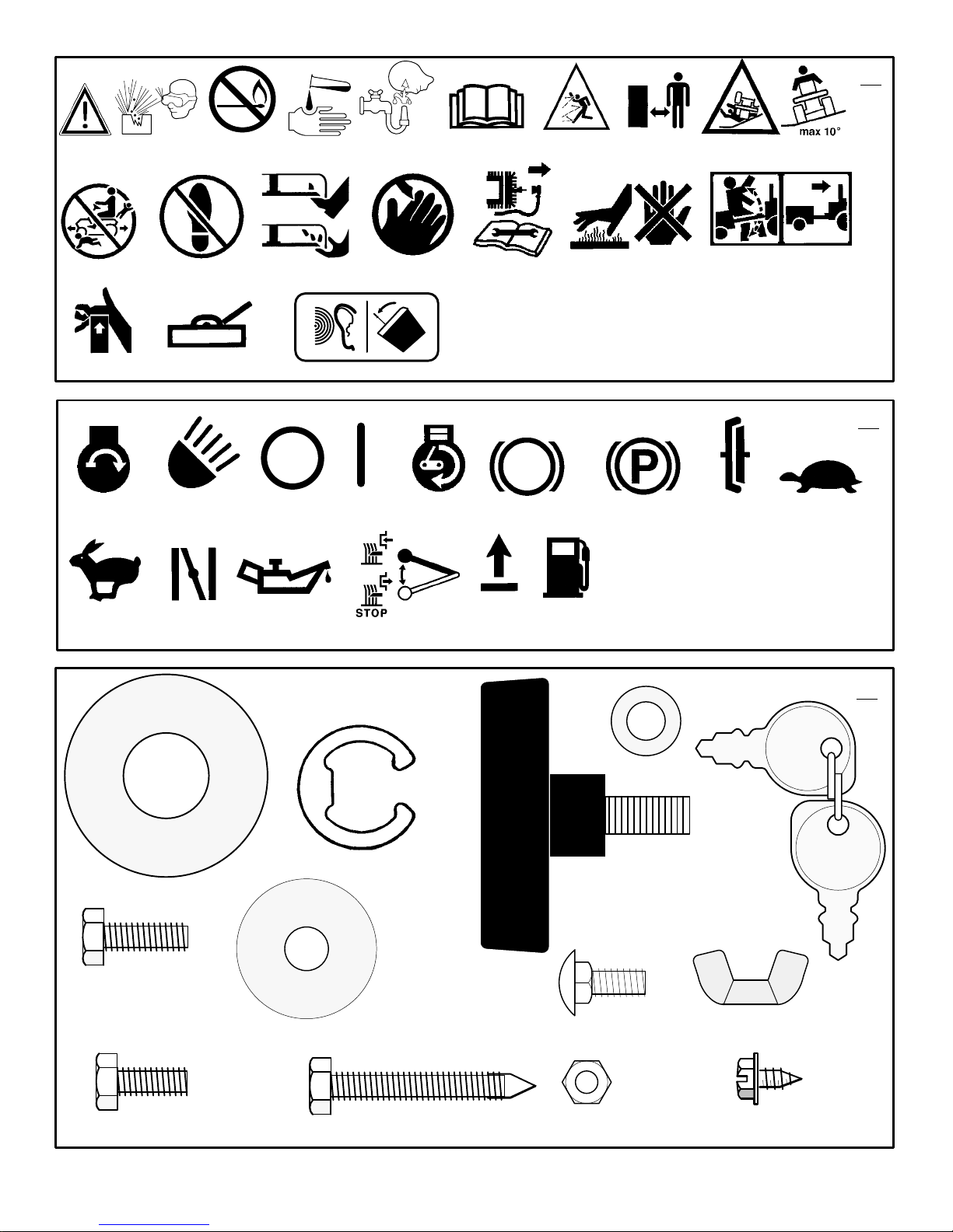
INTERNATIONAL PICTORIALS
IMPORTANT: The following pictorials are located on your unit or on literature supplied
with the product. Before you operate the
unit, learn and understand the purpose for
each pictorial.
NOTE: Illustrations and pictorials begin
on page 2.
Safety Warning Pictorials
1 WARNING
2 Shield Eyes. Explosive Gases Can Cause
Blindness Or Injury.
3 No Sparks, Flames or Smoking.
4 Sulphuric Acid Can Cause Blindness Or
Severe Burns
5 Flush Eyes Immediately With Water. Get
Medical Help Fast.
6 IMPORTANT: Read Owner’s Manual
Before Operating This Machine.
7 WARNING: Thrown Objects. Keep
(Figure 37)
Bystanders Away. Read User Instructions
Before Operating This Machine.
8 WARNING: Do Not Use This Machine On
Slopes Greater Than 10 Degrees.
9 DANGER: Keep People, Especially
Children, Away From Unit.
10 DANGER: No Step.
11 DANGER: Keep Feet And Hands Away
From Rotating Blade.
12 DANGER: Keep Hands Away From
Rotating Blade.
13 DANGER: Disconnect Spark Plug Wire
Before Servicing Unit.
14 WARNING: Hot Surface.
15 WARNING: Use Caution When Connecting
Or Disconnecting Accessories.
16 WARNING: Crushed Fingers.
17 IMPORTANT: Follow Instructions In
Owner’s Manual To Level The Deck.
18 WARNING: When you hear the audible
alarm it is time to empty the grass bagger.
Control And Operating Pictorials
(Figure 38)
1 Engine Start
2 Lights
3 Engine Run
4 Engine Stop
5 Engine Run
6 Brake
7 Parking Brake
8 Clutch
9 Slow
10 Fast
11 Choke
12 Oil
13 Blade Rotation Control
14 Raise
15 Fuel
MADE IN USA BY MURRAY INC.
JACKSON, TENNESSEE
FOR
CODE144S
13/40 TRACTOR
REAR COLLECT
RPM 2400
236
2000
144S001002
F–000786J
Declared vibration emission values in accordance with Directive 89/392/EEC.
Vibration Emission according to BS EN 1032: Seat < 0,50 m/s2,
Right Running Board 1,01 m/s2, Left Running Board 0,76 m/s2
Vibration Emission according to BS EN 1033: Steering Wheel 4,96 m/s
Values determined with operator in operating position when the machine was
operated stationary on a grass covered surface at 2400 min–1.
Declared airborne noise emissions in accordance with Directive 84/538/EEC.
Sound Power Level 100 dB(A)
Sound Pressure Levels
at operator ears 86,1 dB(A) left; 85,5 dB(A) right.
Values determined at ear according to the specifications of 81/1051/EEC.
2
12

OWNER’S INFORMATION
Know your product: If you understand the unit
and how the unit operates, you will get the best
performance. As you read this manual, compare
the illustrations to the unit. Learn the location
and the function of the controls. To help prevent
an accident, follow the operating instructions
and the safety rules. Keep this manual for future
reference.
WARNING: Look for this symbol to indicate
important safety precautions. This symbol
indicates: “Attention! Become Alert! Your
Safety Is At Risk.”
Responsibility Of The Owner
WARNING: This cutting machine is
capable of amputating hands and
feet and throwing objects. Failure
to observe the following safety instructions
could result in serious injury or death to
the operator or bystanders.
The responsibility of the owner is to
follow the instructions below.
SAFE OPERATION PRACTICES
For Ride–On (Riding)
Rotary Mower Machines
Training
1. Read the instructions carefully. Be familiar
with the controls and the proper use of the
equipment.
2. Never allow children or people unfamiliar
with these instructions to use the mower.
Local regulations may restrict the age of
the operator.
3. Never mow while people, especially
children, or pets are nearby.
4. Keep in mind that the operator or user is
responsible for accidents or hazards occurring to other people or their property.
5. Do not carry passengers.
6. All drivers should seek and obtain professional and practical instruction. Such
instruction should emphasize:
a. the need for care and concentration
when working with ride–on machines;
b. control of a ride–on machine sliding
on a slope will not be regained by the
application of the brake. The main
reasons for loss of control are:
insufficient wheel grip;
being driven too fast;
inadequate braking
the type of machine is unsuitable
for its task;
lack of awareness of the effect of
ground conditions, especially
slopes;
incorrect hitching and load dis-
tribution.
Preparation
1. While mowing, always wear substantial
footwear and long trousers. Do not operate
the equipment when barefoot or wearing
open sandals.
F–000786J
2. Thoroughly inspect the area where the
equipment is to be used and remove all objects which may be thrown by the machine.
3. WARNING – Petrol is highly flammable.
a. Store fuel in containers specifically de-
signed for this purpose.
b. Refuel outdoors only and do not
smoke while refuelling.
c. Add fuel before starting the engine.
Never remove the cap of the fuel tank
or add petrol while the engine is running or when the engine is hot.
d. If petrol is spilled, do not attempt to
start the engine but move the machine
away from the area of spillage and
avoid creating any source of ignition
until petrol vapours have dissipated.
e. Replace all fuel tanks and container
caps securely.
4. Replace faulty silencers.
5. Before using, always visually inspect to see
that the blades, blade bolts and cutter assembly are not worn or damaged. Replace
worn or damaged blades and bolts in sets
to preserve balance.
6. On multi–blade machines, take care as rotating one blade can cause other blades to
rotate.
Operation
1. Do not operate the engine in a confined
space where dangerous carbon monoxide
fumes can collect.
2. Mow only in daylight or in good artificial
light.
3. Before attempting to start the engine, disengage all blade attachment clutches and
shift into neutral.
4. Do not use on slopes of more than 10 degrees.
5. Remember there is no such thing as a
“safe” slope. Travel on grass slopes requires particular care. To guard against
overturning:
a. do not stop or start suddenly when
going up or downhill;
b. engage clutch slowly, always keep
machine in gear, especially when travelling downhill;
c. machine speeds should be kept low
on slopes and during tight turns;
d. stay alert for humps and hollows and
other hidden hazards;
e. never mow across the face of the
slope, unless the mower is designed
for this purpose.
6. Use care when pulling loads or using heavy
equipment.
a. Use only approved drawbar hitch
points.
b. Limit loads to those you can safely
control.
c. Do not turn sharply. Use care when
reversing.
d. Use counterweight(s) or wheel
weights when suggested in the Instruction Book.
7. Watch out for traffic when crossing or near
roadways.
8. Stop the blades rotating before crossing
surfaces other than grass.
9. When using any attachments, never direct
discharge of material toward bystanders
13
GB
nor allow anyone near the machine while in
operation.
10. Never operate the mower with defective
guards or shields, or without safety protective devices in place.
11. Do not change the engine governor settings or overspeed the engine. Operating
an engine at excessive speed may increase the hazard of personal injury.
12. Before leaving the operator’s position
a. disengage the power take–off and
lower the attachments;
b. change into neutral and set the park-
ing brake;
c. stop the engine and remove the key.
13. Disengage drive to attachments, stop the
engine, and disconnect the spark plug
wire(s) or remove the ignition key
a. before cleaning blockages or unclog-
ging chute;
b. before checking, cleaning or working
on the mower;
c. after striking a foreign object. Inspect
the mower for damage and make repairs before restarting and operating
the equipment;
d. if the machine starts to vibrate abnor-
mally (check immediately).
14. Disengage drive to attachments when
transporting or not in use.
15. Stop the engine and disengage drive to attachment
a. before refuelling;
b. before removing the grass catcher;
c. before making height adjustment un-
less adjustment can be made from the
operator’s position.
16. Reduce the throttle setting during engine
run–out and, if the engine is provided with a
shut–off valve, turn the fuel off at the conclusion of mowing.
17. Before and when backing, look behind and
down for small children.
18. Use extra care when approaching blind
corners, shrubs, trees or other objects that
may obscure vision.
Maintenance and Storage
1. On multi–blade machines, take care as rotating one blade can cause other blades to
rotate.
2. When machine is to be parked, stored or
left unattended, lower the cutting means
unless a positive mechanical lock is used.
3. Keep all nuts, bolts, and screws tight to be
sure the equipment is in safe working
condition.
4. Never store the equipment with petrol in the
tank inside a building where fumes may
reach an open flame or spark.
5. Allow the engine to cool before storing in
any enclosure.
6. To reduce the fire hazard, keep the engine,
silencer, battery compartment and petrol
storage area free of grass, leaves, or excessive grease.
7. Check the grass catcher frequently for
wear or deterioration.
8. Replace worn or damaged parts for safety.
9. If the fuel tank has to be drained, this
should be done outdoors.

ASSEMBLY
n
f
All fasteners are in the parts bag. Do not discard
any parts or material until the unit is assembled.
WARNING: Before doing any assembly or maintenance to the
mower, remove the wire from the
spark plug.
NOTE: In this instruction book, left and right
describe the location of a part with the operator on the seat.
NOTE: Illustrations and pictorials begin on
page 2.
NOTE: To assemble the following loose
parts, use the fasteners shown at full size in
Figure 39.
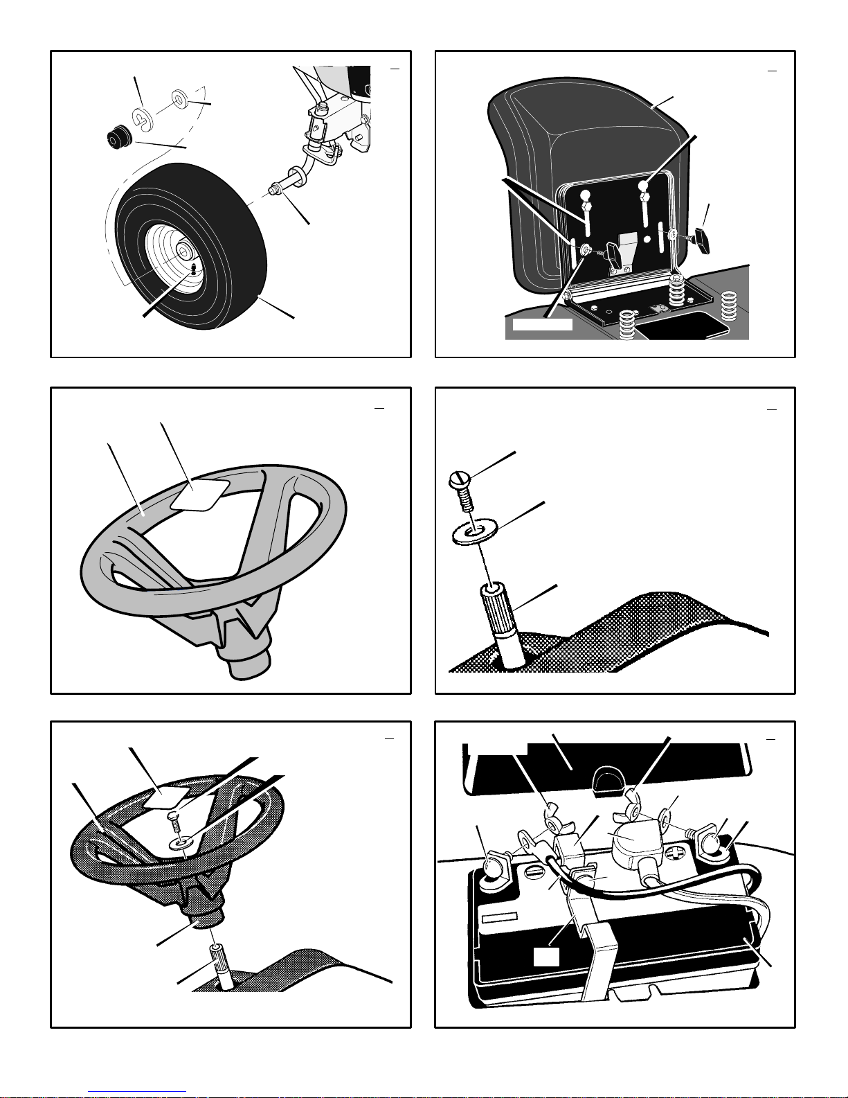
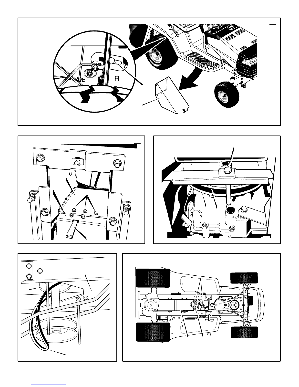
How To Install The Front Wheels
(Figure 1)
Use a knife and cut the four sides of the container.
Install the front wheels (1) in the container.
NOTE: Use a piece of wood about 4 feet (1.25
meters) long to raise the front of the tractor.
If a piece of wood cannot be found, get
another person to help lift the tractor. Be
careful, do not let the tractor fall.
1. Raise the front of the tractor. Set a support
(block of wood) under the tractor.
2. Make sure the valve stem (2) is to the outside of the tractor. Slide the front wheel (1)
on the spindle (3).
3. Fasten each front wheel (1) with washer (4)
and e–ring (5).
4. After the front wheels (1) are installed, lift
the tractor from the support. Roll the tractor
off of the container.
5. If your tractor has hub caps (6), install the
hub caps (6). Make sure the washers (4)
hold the hub caps (6) in place.
How To Install The Seat
1. Carefully remove the plastic bag from the
seat (1).
NOTE: For shipping purposes, the fas-
teners may be attached to the seat. Before proceeding, remove the fasteners.
2. Align the holes in the seat hinge (2) to the
bolts in the seat (1). Fasten the seat (1) to
the seat hinge (2) with the fasteners (4) and
(5).
3. Check the operating position of the seat (1).
If the seat (1) needs to be adjusted, loosen
the two wing bolts (5). Slide the seat (1) for-
ward or backward along the seat adjusting
holes (3). Tighten the wing bolts (5).
How To Assemble The Steering Wheel
1.
(Figure 3)
cover (1) is taped to the center of the steer-
ing wheel (2). Remove the hub cover (1)
and set aside.
2.
(Figure 4)
(2) from the steering post (3) and set aside.
3. Make sure the front wheels point forward.
4.
(Figure 5)
make sure the split spoke (5) of the steering
wheel in pointing toward you. Slide the steer-
ing wheel (1) onto the steering post (2).
5. Use screw (6) and washer (7), set aside
earlier, to secure the steering wheel (1).
Tighten the screw (6). DO NOT over tighten.
F–000786J
For shipping purposes, the hub
Remove screw (1) and washers
From the operator’s position,
(Figure 2)
6. Remove the adhesive backing from the hub
cover (3) that was set aside earlier. Attach
the hub cover (3) to the center of the steering wheel (1).
7. Some models have an
parts bag. Attach the decal to the center of
the steering wheel (1).
Maintenance Free Battery
IMPORTANT: Before you attach the battery
cables to the battery, check the battery date.
The battery date tells if the battery must be
charged.
1. Check the top of the battery (1) for the location of the battery date.
2. If the battery (1) is put into service
the battery date, the battery cables can be
attached without charging the battery (1).
See “How To Install The Battery Cables”.
3. If the battery (1) is put into service
battery date, the battery (1) must be
charged. See “How To Charge The Maintenance Free Battery”.
optional
(Figure 6)
decal in the
before
after
the
How To Charge The Battery
WARNING: When you charge the
battery, do not smoke. Keep the bat-
fumes from the battery acid can cause an
explosion.
1.
2. Remove the fasteners (9) from the battery
3.
4. Remove battery bracket (11).
5. Remove the battery (1).
6. Remove the protective caps from the battery
7. Use a 12 volt battery charger to charge the
8. Install the battery (1).
9. Install battery brackets (10, 11).
NOTE: Make sure battery brackets (10, 11)
are installed into the slots in the frame (12)
before tightening the fasteners.
tery away from any sparks. The
(Figure 6)
brackets (10, 11).
(Figure 7)
(10) and remove battery bracket (10) from
frame (12) as shown.
terminals.
battery (1). Charge at a rate of 6 amperes
for one hour. If you do not have a battery
charger, have an authorized service centre
charge the battery.
Remove the battery cover (3).
WARNING: To prevent sparks, do
not touch the battery brackets to
the terminals.
Apply pressure to battery bracket
How To Install The Battery Cables
(Figure 6)
WARNING: To prevent sparks, faste
the red cable to the positive (+) ter-
cable.
1. Remove the protective caps from the battery
2. Fasten the red cable (5) to the positive (+)
minal before you connect the black
terminals.
NOTE: For shipping purposes, the fasteners may be attached to the battery terminals. Remove the fasteners before
proceeding.
terminal (4) with the fasteners (6) and (7).
Slide the terminal cover (2) onto the positive (+) terminal (4).
14
GB
3. Fasten the black cable 8 to the negative (–)
terminal with the fasteners (6) and (7).
4. Install the battery cover (3).
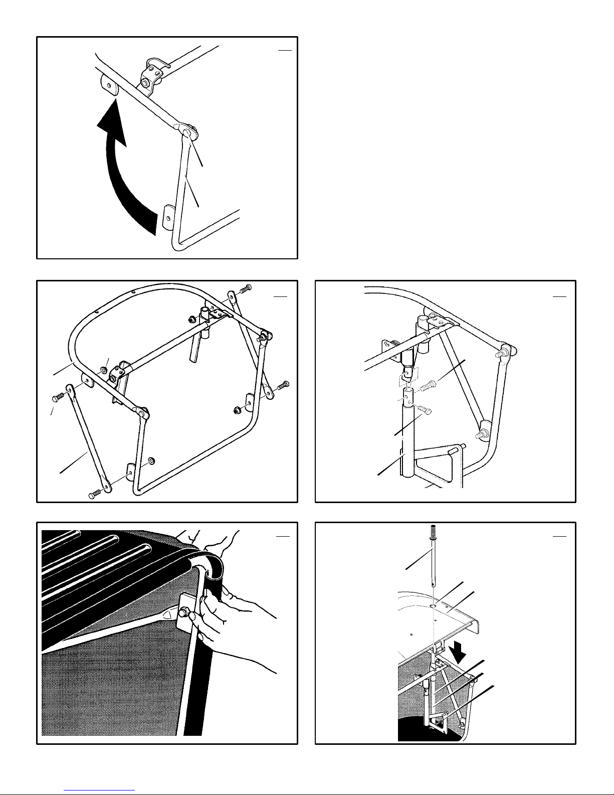
How To Assemble The Grass Bagger
1. Put the grass bagger on a flat surface.
2.
(Figure 26)
teners (2).
3.
(Figure 27)
assembly (1) with screws (3) and nuts (4).
Make sure all fasteners are tight.
4.
(Figure 28)
brackets (3) with the fasteners as shown.
5.
(Figure 29)
6.
(Figure 30)
bagger assembly (1), slide the handle (5) in
the tube (6).
7. Fasten the handle (5) with screw (7).
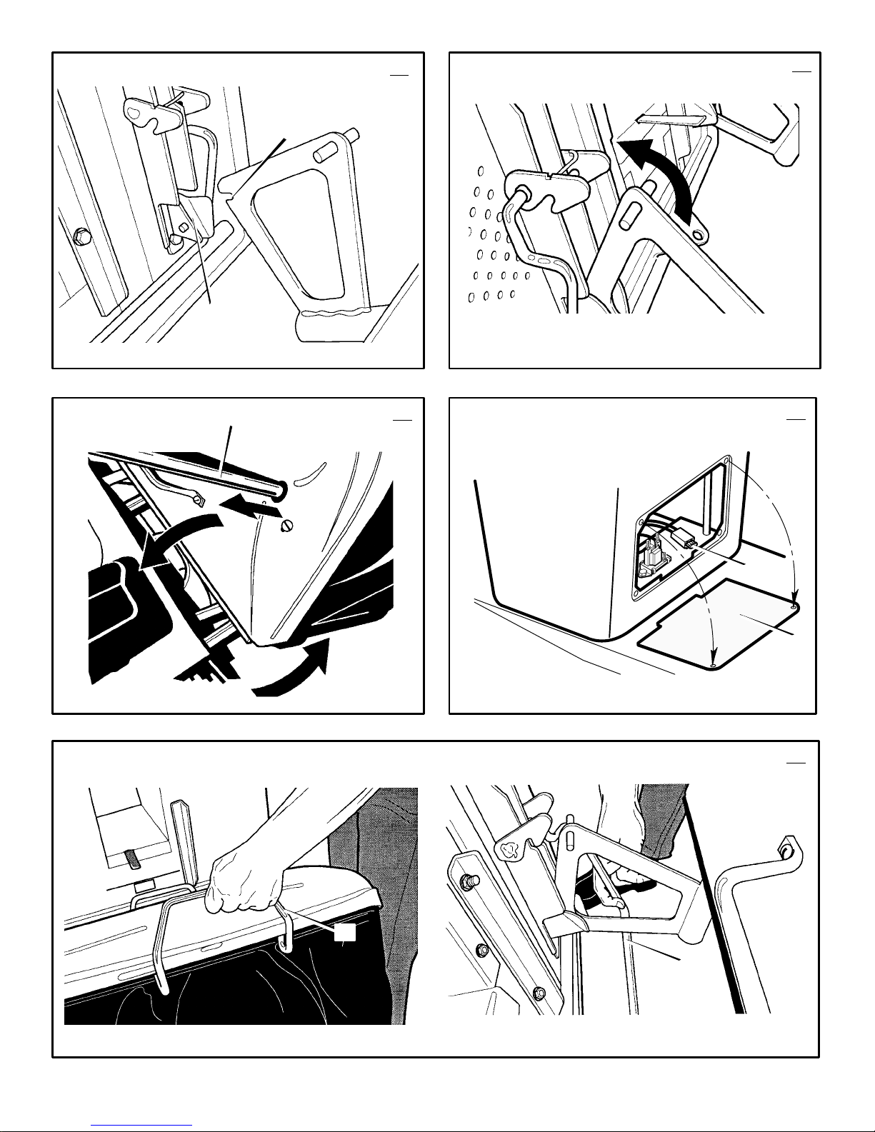
How To Mount
The Grass Bagger On The Tractor
1.
(Figure 31)
brackets (3) onto the pins (4) on the back
plate of the tractor.
2.
(Figure 32)
grass bagger in operating position. Snap into
place.
How To Prepare The Engine
NOTE: The engine was shipped from the factory filled with oil. Check the level of the oil.
Add oil as needed.
See the engine manufacturer’s instructions for the
type of petrol and oil to use. Before you use the
unit, read the information on safety, operation,
maintenance, and storage.
safety petrol container. Do not smoke when
adding petrol to the engine. When inside an
enclosure, do not fill with petrol. Before you
add petrol, stop the engine. Let the engine
cool for several minutes.
Check The Tyres
Check the air pressure in the tyres. Tyres with too
much air pressure will cause the unit to ride rough.
Also, the wrong air pressure will keep the mower
housing from cutting level. The correct air pressure is: Front Tyres 1,38 BAR (20 PSI), Rear
Tyres 0,97 BAR (14 PSI). The tyres were over inflated for shipment.
Check The Level Of The Mower Housing
Make sure the level of cut is still correct. After you
mow a short distance, look at the area that was cut.
If the mower housing does not cut level, see the instructions on “How To Level The Mower Housing”
in the Maintenance section of this instruction book.
Important! Before You Start Mowing
Check the engine oil.
Fill the fuel tank with petrol.
Check the level of the mower housing.
Check the air pressure of the tyres.
Attach the battery cables.
Open the frame (1). Tighten fas-
Attach braces (2) to the frame
Attach the bag support
Secure the bag to the frame.
On the left side of the grass
Mount the slots on the support
Hold rear handle and rotate the
WARNING: Follow the engine manufacturer’s instructions for the type o
petrol and oil to use. Always use a

OPERATION
NOTE: Illustrations and pictorials begin on
page 2.
Location Of Controls
Blade Rotation Control (1): Use the blade rota-
tion control to start and stop the rotation of the
blade.
Clutch / Brake Pedal (2): The pedal has two functions. The first function is a clutch. The second
function is a brake.
Headlight Switch (3): The headlight switch is the
first part of the ignition switch. T o use the lights with
the engine running, turn the key to the position for
the lights.
Ignition Switch (3): Use the ignition switch to
start and stop the engine.
Shift Lever (4): Use the shift lever to change the
speed of the unit.
Lift Lever (5): Use the lift lever to change the
height of cut.
Parking Brake Lever (6): Use the parking brake
lever to engage the brake when you leave the unit.
Throttle Control Lever (7): Use the throttle control lever to increase or decrease the speed of the
engine. For models without a choke control button, the choke is regulated with the throttle control
lever.
Choke Control Button (9): If equipped, use to
start cold engine.
Grass Bagger Full Indicator (10): When you
hear the audible alarm the grass bagger is full.
Move the blade rotation control (1) to the DISENGAGE position to turn audible alarm off and
see the “How To Empty The Grass Bagger” instructions in this section.
Attachments
This unit can use many different attachments. This
unit can pull attachments like a lawn sweeper, a
lawn aerator, or a hopper spreader. This unit can
not use attachments that engage the ground like a
plough, a disk harrow, or a cultivator.
For trailer and pull–behind attachments, the maximum weight is 113 kg (250 lbs.).
How To Use The Throttle Control
(Figure 8)
Use the throttle control (7) to increase or decrease the speed of the engine.
1. The FAST position is marked with a detent.
For normal operation and when using a
grass bagger, move the throttle control to the
FAST position. For maximum charging of the
battery and for a cooler running engine, operate the engine in the FAST position.
2. The engine governor is set at the factory for
maximum performance. Do not adjust the
governor to increase the speed of the engine.
How To Use The Blade Rotation Control
(Figure 8)
Use the blade rotation control (1) to engage the
blade(s).
1. Before you start the engine, make sure the
blade rotation control (1) is in the DISENGAGE position.
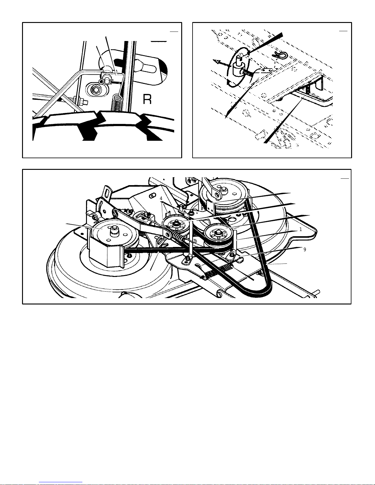
2.
(Figure 11)
trol (1) to the ENGAGE position to rotate the
blade(s).
F–000786J
Move the blade rotation con-
(Figure 8)
NOTE: If the engine stops when you engage the blade(s), the seat switch is not
activated or the bag is not closed properly. Make sure you sit in the middle of the
seat.
3. Move the blade rotation control (1) to the
DISENGAGE position to stop the blade(s).
Before you leave the operator’s position,
make sure the blade(s) has stopped rotating.
4. Before you ride the unit across a sidewalk or
a road, move the blade rotation control (1)
to the DISENGAGE position.
WARNING: Always keep your
hands and feet away from the
mower housing when the engine runs.
How To Use The Shift Lever
To change the forward speed or the direction of the
unit, follow the steps below.
CAUTION: Before you move the shift lever,
completely push the clutch/brake pedal forward to stop the unit. If the unit is not
stopped, the gearbox can be damaged.
1. Completely push the clutch/brake pedal (2)
2. Move the throttle control lever (3) to the
3. To go forward, move the shift lever (4) to a
4. Slowly release the clutch/brake pedal (2).
5. Move the throttle control (7) to the FAST
blade, deflector opening, and the
(Figure 8)
forward to stop the unit. Keep your foot on
the pedal.
SLOW position.
forward speed setting. To go backward,
move the shift lever (4) to reverse.
Do not keep your foot on the pedal.
position.
How To Use The Parking Brake
(Figure 8)
1. Completely push the clutch/brake pedal (2)
forward.
2. Lift the parking brake lever (6).
3. Remove your foot from the clutch/brake
pedal (2) and then release the parking
brake lever (6). Make sure the parking brake
will hold the unit.
4. To release the parking brake (6), completely
push the clutch/brake pedal (2) forward.
The parking brake will automatically release.
WARNING: Before you leave the
operator’s position, move the shift
the parking brake. Move the blade rotation
control to the DISENGAGE position. Stop
the engine and remove the ignition key.
lever to the neutral (N) position. Set
How To Change The Cutting Height
(Figure 8)
T o change the cutting height, raise or lower the lift
lever (5) as follows.
1. Move the lift lever (5) forward to lower the
mower housing and back to raise the mower
housing.
2. When you ride on a sidewalk or road, move
the lift lever (5) to the highest position and
move the blade rotation control(1) to the
DISENGAGE position.
15
GB
How To Stop The Unit
1. Completely push the clutch/brake pedal (2)
forward to stop the unit. Keep your foot on
the pedal.
2. Move the blade rotation control (1) to the
DISENGAGE position.
3. Move the shift lever (4) to the NEUTRAL
position.
4. Set the parking brake (6).
WARNING: Make sure the parking
brake will hold the unit.
5. Move the throttle control (7) to the SLOW
position.
6. To stop the engine, turn the ignition key (3)
to the OFF position. Remove the key.
How To Transport The Unit
To transport the unit, follow the steps below.
1. Move the blade rotation control to the DISENGAGE position.
2. Raise the lift lever to the highest position.
3. Move the throttle control to a position between SLOW and FAST.
4. To go faster, move the shift lever to a faster
speed.
How To Operate With The Mower
Housing
IMPORTANT: When you operate with the
mower housing, always operate with the
throttle control in the FAST position.
1. Start the engine.
2. Move the lift lever to a height of cut position.
In high or thick grass, cut the grass in the
highest position first and then lower the
mower housing to a lower position.
3. Move the throttle control to the SLOW position.
4. Slowly move the blade rotation control to the
ENGAGE position.
5. Push the clutch/brake pedal completely forward.
6. Move the shift lever to one of the speed settings.
NOTE: When you mow in heavy grass or
mow with a bagger, put the shift lever in
the slowest speed.
7. Slowly release the clutch/brake pedal.
8. Move the throttle control to the FAST position. If you need to go faster or slower, stop
the unit and move the shift lever to another
speed setting.
9. Make sure the level of cut is still correct.
After you mow a short distance, look at the
area that was cut. If the mower housing does
not cut level, see the instructions on “How To
Level The Mower Housing” in the Maintenance section.
WARNING: For better control of the
unit, select a safe speed.
How To Operate On Hills
WARNING: Do not ride up or down
slopes that are too steep to back
straight up. Never ride the unit
across a slope.
1. Before you ride up or down a hill, move the
shift lever to the slowest speed.
2. Do not stop or change speed settings on a
hill. If you must stop, quickly push the clutch/
(Figure 8)

brake pedal forward and set the parking
brake.
3. To start again, make sure the shift lever is in
the slowest speed. Move the throttle control
to the SLOW position. Slowly release the
pedal.
4. If you must stop or start on a hill, always
have enough space for the unit to roll when
you release the brake and engage the clutch.
5. Be very careful when you change directions
on a hill. When on a slope or in a turn on a
hill, move the throttle control to the SLOW
position to help prevent an accident.
WARNING: Never store the grass
bagger with grass clippings in the
bags. Even a small amount of
grass or debris can generate enough heat
to start a fire.
WARNING: Do not operate unless
the entire grass bagger attachment
is in place.
How To Empty The Grass Bagger
(Figure 33)
1. Move the blade rotation control to the DISENGAGED position.
2. While sitting on the seat, lift and pull the
handle (1) forward to the DUMP position.
3. Drive slowly forward to allow the grass to fall
out of the bag.
4. Push the handle rearward and down to the
OPERATING position.
NOTE: If the engine stops when you engage
the blade(s), the seat switch is not activated
or the grass bagger is not locked in place.
Before Starting The Engine
Check the oil
NOTE: The engine was shipped from the factory filled with oil. Check the level of the oil.
Add oil as needed. See the engine manufacturer’s instructions for the type of petrol and
oil to use.
1. Make sure the unit is level.
NOTE: Do not check the level of the oil
while the engine runs.
2. Check the oil. Follow the procedure in the
engine manufacturer’s instructions.
3. If necessary, add oil until the oil reaches the
FULL mark on the dipstick. The quantity of oil
needed from ADD to FULL is shown on the
dipstick. Do not add too much oil.
Add Petrol
WARNING: Always use a safety
petrol container. Do not smoke
when adding petrol to the fuel tank.
Do not add petrol when you are inside an
enclosure. Before you add petrol, stop the
engine and let the engine cool for several
minutes.
(Figure 9)
position with regular unleaded petrol. Do not use
premium unleaded petrol. Make sure the petrol is
fresh and clean. Leaded petrol will increase deposits and shorten the life of the valves.
NOTE: Open fuel shut off valve 1/4 turn, if
equipped.
F–000786J
Fill the fuel tank (1) to the FULL (2)
How To Start The Engine
WARNING: The electrical system
has an operator presence system
that includes a sensor switch for
the seat. These components tell the
electrical system if the operator is sitting
on the seat. This system will stop the
engine when the operator leaves the seat if
the blade rotation control is engaged or if
the transmission is engaged. For your
protection, always make sure this system
operates correctly.
NOTE: The engine will not start unless you
depress the clutch/brake pedal or engage
the parking brake and move the blade rotation control to the DISENGAGE position.
1. Push the clutch/brake pedal completely forward. Keep your foot on the pedal.
2. Move the shift lever to the neutral (N) position.
3. Make sure the blade rotation control is in the
DISENGAGE position.
4. Move the throttle control completely forward
to the CHOKE or FAST position. Some models have a separate choke knob. Pull the
choke knob to the full CHOKE position.
5. Turn the ignition key to the START position.
NOTE: If the engine does not start after
four or five tries, move the throttle control
to the FAST position. Again try to start the
engine. If the engine will not start, see the
TROUBLE SHOOTING CHART.
6. Slowly move the throttle control to the SLOW
position.
7. To start a hot engine, move the throttle control to a position between FAST and SLOW.
Mowing And Bagging Tips
1. For a lawn to look better, check the cutting
level of the mower housing. See “How To
Level The Mower Housing” in the Maintenance section.
2. For the mower housing to cut level, make
sure the tyres have the correct amount of air
pressure.
3. Every time you use the unit, check the blade.
If the blade is bent or damaged, immediately
replace the blade. Also, make sure the nut
for the blade is tight.
4. Keep the blade(s) sharpened. Worn blades
will cause the ends of the grass to turn
brown.
5. Do not cut or bag grass that is wet. Wet
grass will not discharge correctly. Let the
grass dry before cutting.
6. If the grass is very high, cut two times to decrease the load on the engine. First cut with
the mower housing in the highest position
and then lower the mower housing for the
second cut.
7. Operate the engine with the throttle in FAST
position and the shift lever in first or second
gear.
8. After each use, clean the bottom and top of
the mower housing for better performance.
Also, a clean mower housing will help prevent a fire.
MAINTENANCE
NOTE: Illustrations and pictorials begin on
page 2.
16
GB
General Recommendations
1. The owner’s responsibility is to maintain this
product. This will extend the life of the product and is also necessary to maintain warranty coverage.
2. Check the spark plug, drive brake, lubricate
the unit, and clean the air filter once a year.
3. Check the fasteners. Make sure all fasteners
are tight.
4. Follow the Maintenance section to keep the
unit in good operating condition.
WARNING: Before you make an inspection, adjustment, or repair to
the unit, disconnect the wire to the
spark plug. Remove the wire from the
spark plug to prevent the engine from
starting by accident.
NOTE: Torque is measured in foot pounds
(metric Nm). This measurement describes
how tight a nut or bolt must be. The torque is
measured with a torque wrench.
Inspect Blade
hits an object, stop the engine. Check the
unit for damage. The blade has sharp
edges. When you hold the blade, use
gloves or cloth material to protect your
hands.
If you keep the blade (1) sharp and inspect the
blade for damage, the blade will cut better and be
more safe to operate. Frequently check the blade
for excessive wear, cracks, or other damage. Frequently check the nut (3) that holds the blade (1).
Keep the nut (3) tight. If the blade hits an object,
stop the engine. Disconnect the wire to the spark
plug. See if the blade is bent or damaged. Check
the blade adapter (5) for damage. Before you operate the unit, replace damaged parts with original
equipment parts. See the authorized service
centre in your area. Every three years, have an authorized service person inspect the blade or replace the old blade with an original equipment part.
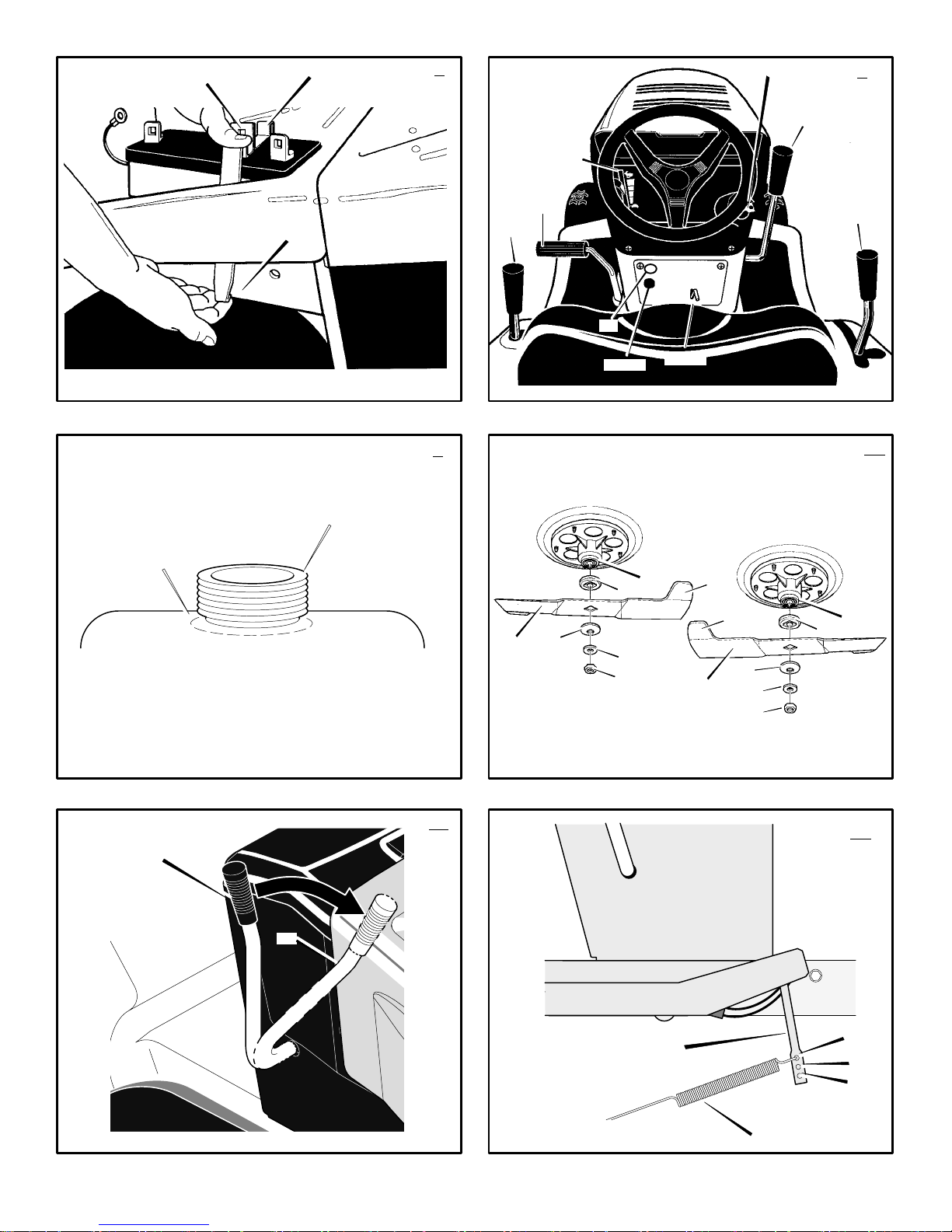
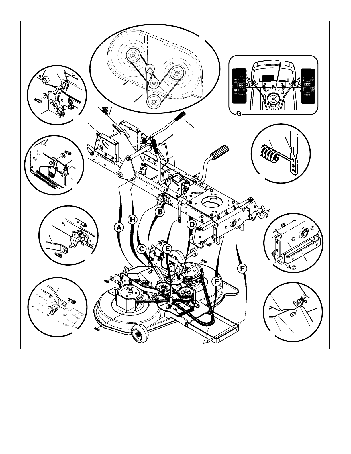
How To Remove And Install The Blade
(Figure 10)
1. Remove the mower housing. See the instructions on “How To Remove The Mower Housing”.
2. Use a piece of wood to keep the blade from
rotating.
3. Remove the nut (3) that holds the blade (1).
4. Check the blade (1) and the blade adapter
(5) according to the instructions for “Inspect
Blade”. Replace a badly worn or damaged
blade with an original equipment blade. See
an authorized service centre in your area.
5. Clean the top and bottom of the mower housing. Remove all the grass and debris.
6. Mount the blade (1) and blade adapter (5)
on the mandrel (6).
7. Mount the left and right blade (1) so that the
hi–lift edges (7) are up. If the blade is upside down, the blade will not cut correctly
and can cause an accident.
8. Fasten the blade (1) with the original
washers (2,8) and nut (3). Make sure the
outside rim of the Belleville washer (2) is
against the blade (1).
accident.
9. Tighten the nut (3) that holds the blade (1) to
a torque of 45 foot pounds (62 Nm).
(Figure 10)
WARNING: Before you inspect or
remove the blade, disconnect the
wire to the spark plug. If the blade
WARNING: Always keep the nut (3)
tight that holds the blade (1). A
loose nut or blade can cause an
 Loading...