

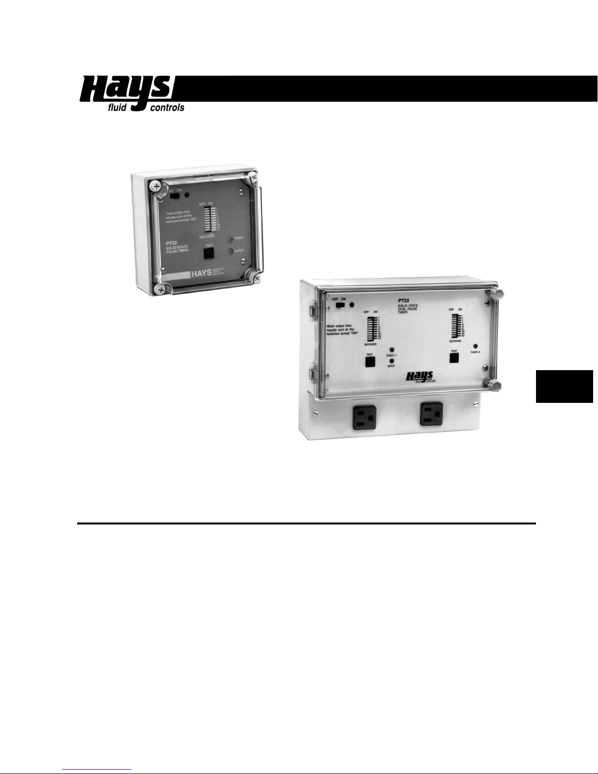
PT32
PT32, PT33
— Pulse Timers
• Solid State Electronics
• Timer Range: 1-1270 seconds
• Low Voltage, low current
• Nema 4 enclosure
• Single Timer (PT32)
• Dual Timer (PT33)
PT33
SPECIAL FEATURES
• Simple Installation and Operation. The PT32 and PT33 are easy to install and operate. Hays
controller are designed to eliminate expensive installation.
• Safe Power Switching with Pulse Meter. For safety, the meter sensor loop is low voltage, low
curent and transformer isolated
• Compatable with all Hays Meters. This gives the ability to match control requirements to the
pulse timer.
• Power, Input and Output Lights. At a glance, you are able to determine process in action.
4-23
• Precise Setting. Digital setting eliminates the trial and error settings of a rotary dial.

4-24
PT32, PT33
TYPICAL APPLICATIONS
• Water treatment
• Proportional feed of chemicals
• Fertilizer injection
• Cooling tower bleed
HOW TO ORDER
Specify: model number and ordering option
• PT32 - Single TImer
• PT33 - Dual Timer
Ordering Options:
• Conduit connection (not output receptacle)
• Sequential timers (PT33 only)
• Third power receptacle (unswitched)(PT33 only)
— Pulse Timers
Example:
Order: PT32 with conduit connection
Single Timer with Nema 4 Rating
SPECIFICATIONS
Power: 115 VAC, 50-60 Hz
Timer Ranges: 1-1270 seconds (21 minutes)
Enclosure: Glass-reinforced polycarbonate
Relay Contact Rating:
5 A resistive at 115 VAC
1/4 Hp inductive at 115 VAC
Sensor: 5 mA at 15 V max.
Shipping Weight:
PT32 - 2 lbs.
PT33 - 4 lbs.

PT32, PT33
— Pulse Timers
INSTALLATION
CAUTION: When this timer is used to control equipment where personal injury or property
damage might occur as a result of timer malfunction, install safeguards which would protect persons and/or equipment in the event of any unexpected operation or failure of the
equipment.
1. Mount the timer to a solid surface as follows: PT32—Gain access to the screw holes by
removing the front cover. Insert a screw through each of the four corner holes and tighten. PT33—
Three screws are required. Drive the center first, before lifting the unit into place. Leave the head of
the screw extending out slightly. Slide the mounting lug in the center of the back over this screw.
Remove the terminal cover to expose the other two screw holes. Insert screws through these holes
and tighten.
2. Connect meter to the timer. Standard units have a built-in meter connector. The mating
connector on the end of the meter cable can be plugged in and secured by a threaded locking ring.
If additional cable to the meter is necessary, two-conductor 24 AWG is recommended. Shielded
cable is not necessary.
3. Connect load to the timer. On the standard PT32, this can be accomplished by plugging a
power cord from the load into the receptacle on the underside of the unit. The PT33 has dual output
receptacles on the lower terminal cover. The receptacle on the left corresponds to the timer on the
left (Timer 1), and the receptacle on the right serves the timer on the right (Timer 2).
4. Connect power to the timer. The cord from standard units may be plugged into any grounded
115 V receptacle.
CAUTION: Always remove power from the unit before making any terminal connections or
removing the faceplate!
SETTING
1. Determine proper output time(s). For best results, the output time should be no longer than
the shortest expected interval between meter pulses. This interval, in seconds, can be calculated:
60
Max. flow (GPM x Pulse Rate (Pulses/Gallon)
If the output time is set longer than this interval, the output will be on continuously as flow nears its
maximum, and proportional output will be lost in the upper part of the flow range.
2. With the front clear cover opened, set the desired output time(s). As the front panel states,
“Total output time equals sum of the switches turned on.” Note that any time between 1 and 1024
seconds can be set by combining switches. For example, to set 43 seconds, first set the 32 sec.
switch on, followed by the 8, and the 2 and 1 (32 + 8 + 2 + 1 = 43). The advantage of this method
soon becomes apparent. Whatever time is set will be the precise output time. It is not necessary to
time the output with a stopwatch and make adjustments.
4-25

4-26
PT32, PT33
— Pulse Timers
OPERATION
1. Turn the power switch “ON.” The power indicator should light.
2. Press the TEST button. The TIMER indicator(s) should light, and stay on for whatever time is
set.
3. When the meter is operating, the INPUT indicator should light periodically, followed by operation of the timer(s). A TIMER light indicates that the timer output relay is on. The PT33 has two
TIMER indicator lights marked “TIMER 1” and “TIMER 2.” Note that at low flows or low pulse rates
(100 G/P) there may be a considerable interval between inputs. Also, at low flow rates, the INPUT
indicator may remain on for some time.
4. Be sure to replace the front cover and tighten screws before leaving the unit in operation.
The PT32/PT33 pulse timer is designed for use with a HAYS MR or ME pulse meter. It can be
used to control a metering pump or valve in a variety of proportional feed or bleed applications. The
timer’s solid-state one-shot logic cycles once for each contact from the meter. Output time is
digitally set at the front of the control, and is very precise across the entire time range of 1-1024
seconds. This elminates the need for trial and error settings using a rotary dial.
For applications requiring a dual timer, the PT33 combines two digital setting units in one
enclosure. They are set independently for any output time from 1 to 1024 seconds.
For safety, the meter sensor loop is low voltage, low current, and fully transformer isolated. It is
designed to be used either with the solid-state sensor of the ME meter or the reed switch sensor of
the MR.
Housings for the PT32 and PT33 controls are wall-mountable non-metallic enclosures with
weathertight clear front covers. On the front panel are the timer setting switches, a power on/off
switch, and a test button which forces one output when pressed. Functions are clearly indicated by
power, input and output lights. The units are supplied standard with power cord and output receptacles—the PT32 has one output receptacle, and the PT33 has two. A conduit mounting option
preserves the NEMA 4x integrity of the enclosure, where this is required.
PT32, PT33
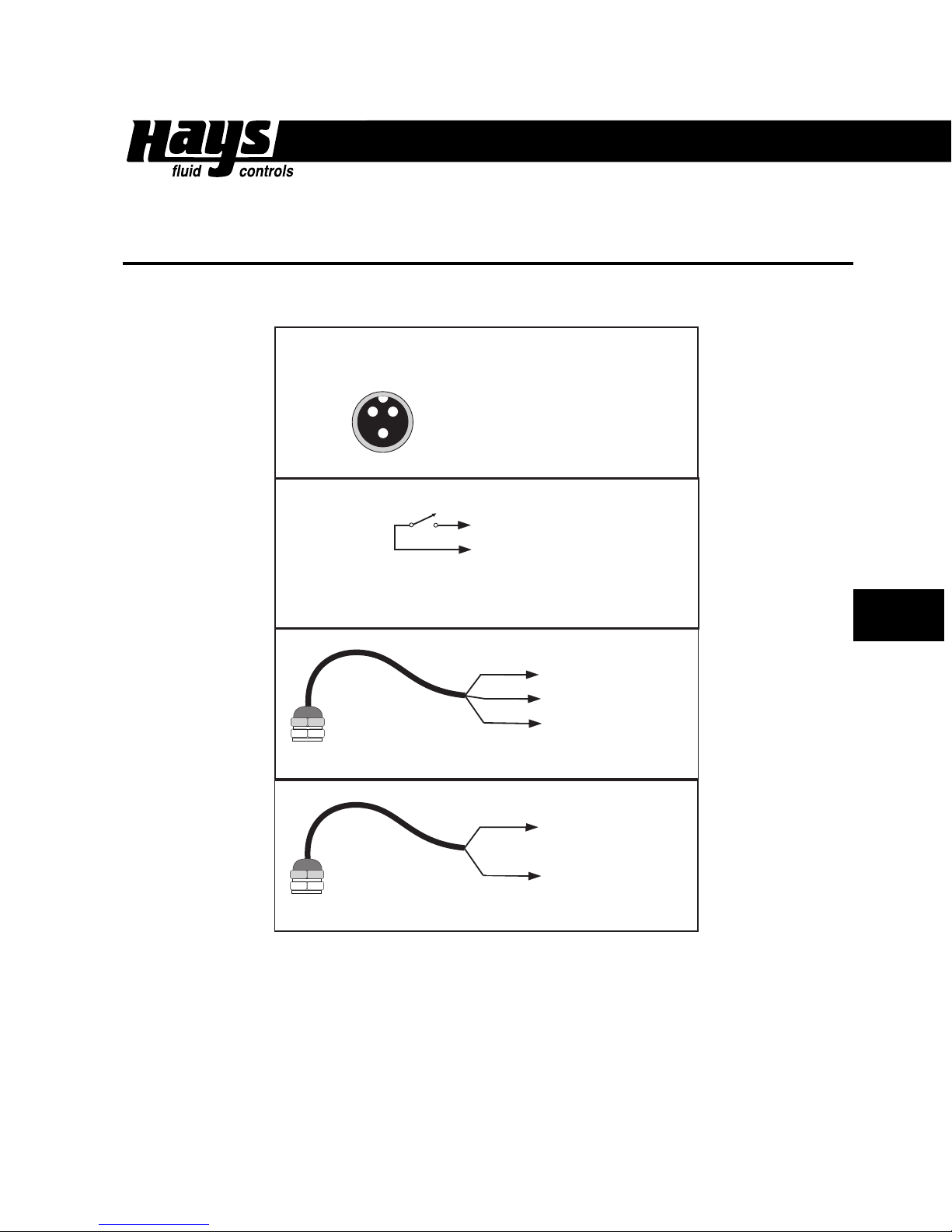
CONNECTION DIAGRAM
INPUT CONNECTIONS
INPUT CONNECTOR
— Pulse Timers
1
CONTACT CLOSURE
ME ELECTRONIC METER
3
2
1 POWER 2 INPUT SIGNAL
3 POWER +
TO CONNECTOR PIN 1
TO CONNECTOR PIN 2
BLACK
WHITE
RED
RED
BLACK
TO CONNECTOR PIN 1
TO CONNECTOR PIN 2
TO CONNECTOR PIN 3
TO CONNECTOR PIN 1
4-27
MT METER
MR METER
BLACK
RED
TO CONNECTOR PIN 2
 Loading...