

Page 1
Electronic Brake Controller
Hayes Brake Controller Company P/N 81760
INSTALLATION MANUAL
For trailers with 2-6 electric brakes and vehicles with 12 volt negative ground systems only.
READ AND SAVE THESE INSTRUCTIONS
• Before beginning installation, read and become familiar with these instructions.
• Leave in tow vehicle for future reference.
• Improper
installation and operation could cause personal injury and/or equipment and
property damage.
SAFETY INFORMATION
!
!
WARNING: Indicates a potentially hazardous situation that,
if not avoided, could result in death or serious, personal injury.
CAUTION: Indicates a potentially hazardous situation that,
if not avoided, could result in damage to product or property.
TIP: Contains helpful information to facilitate installation.
Page 2
Installation
Mounting angle and mounting direction
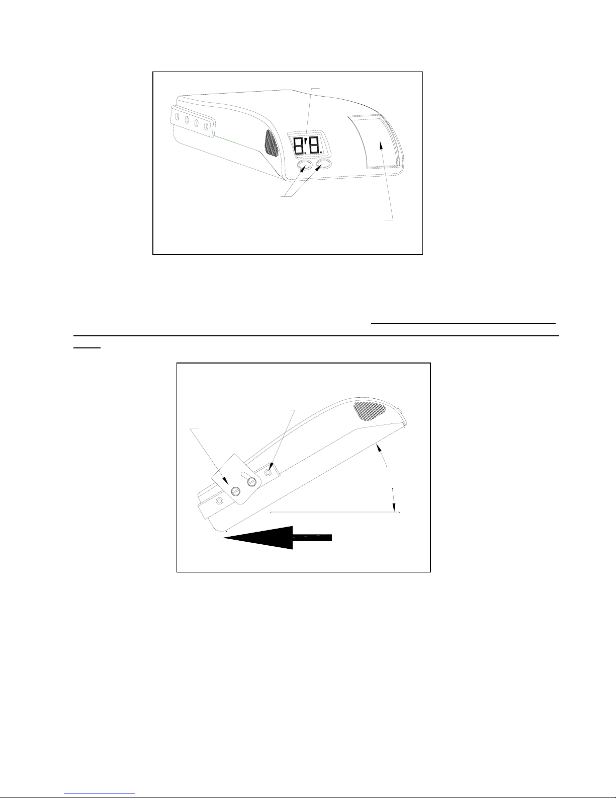
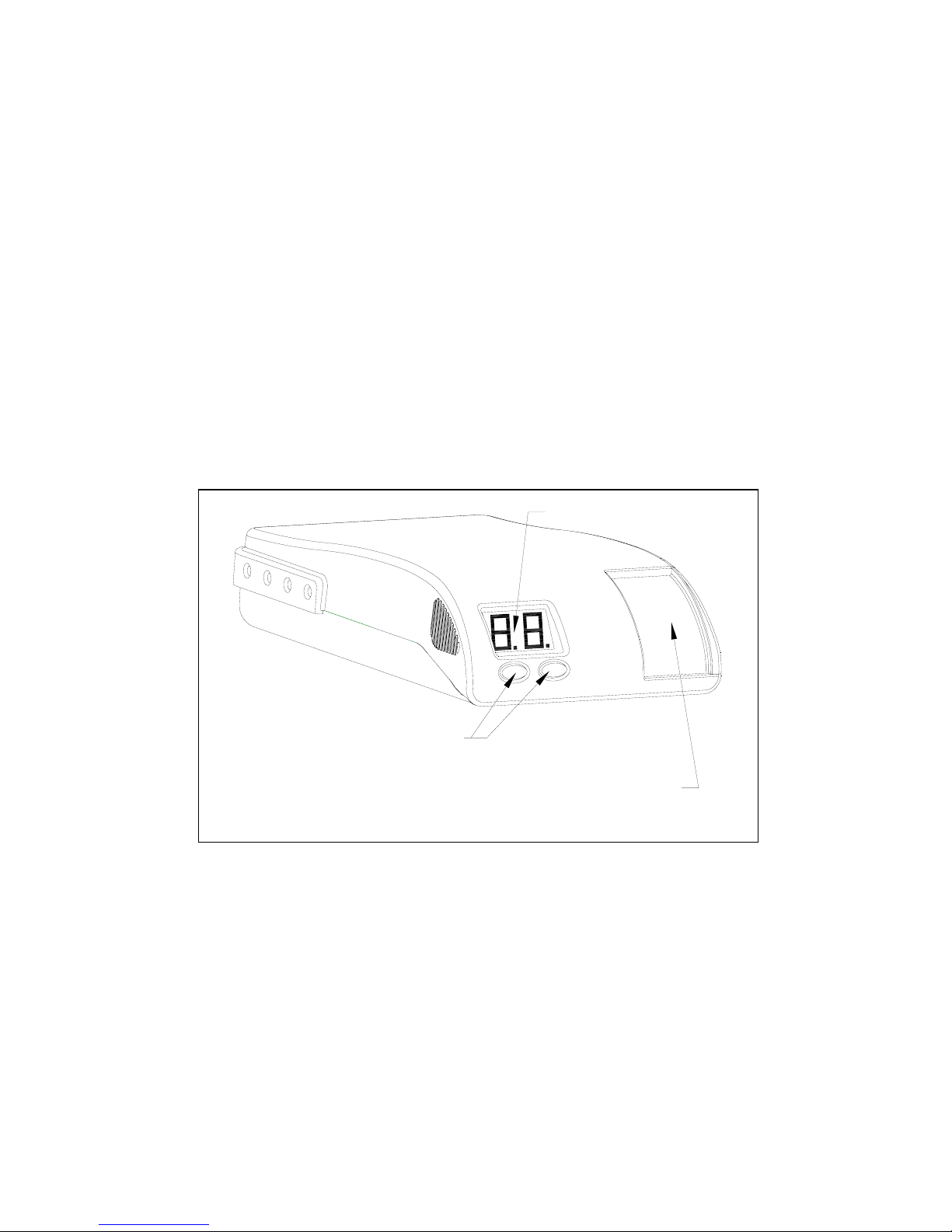
The Engage can be mounted at any angle and in any direction. It must be mounted in a location that
the driver can see and read the display. The driver must be able to reach and operate the manual
slide.
MANUAL OVERRIDE
SLIDE LEVER
DIGITAL DISPLAY
SETUP ADJUSTMENT
BUTTONS
Figure 1 – Front View of Engage
Acceptable Mounting Positions
Any Direction
Anchor Holes
(4 ea. side)
Any Angle
MOUNTING
BRACKET
Figure 2 – Acceptable Mounting Angles
Page 3
Controller Mounting and Installation
Controller and Bracket Mounting
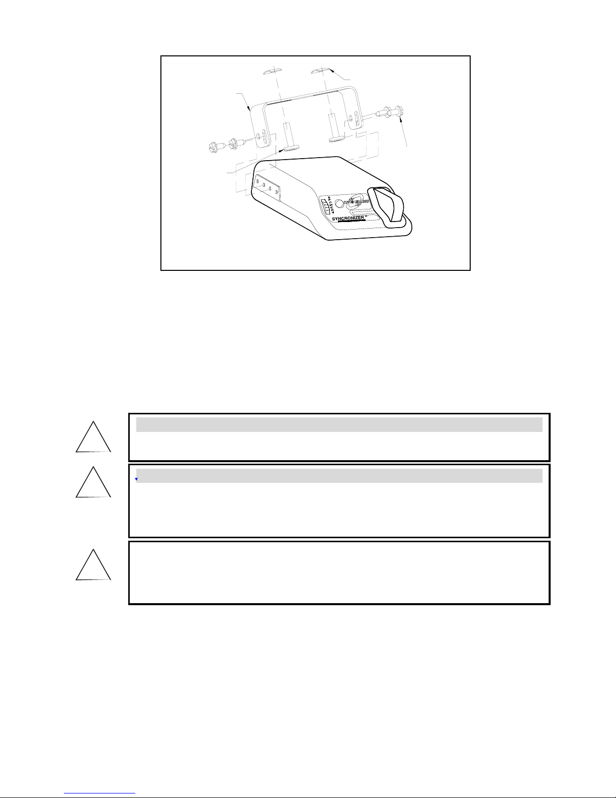
1. Install the mounting bracket to a solid surface under the tow vehicle dash or other suitable location in
the tow vehicle using the two machine screws and fasteners provided. Tighten until snug. See Figure
2 – Acceptable Mounting Angles and Figure 3 – Attachment of Mounting Bracket.
2. Insert four of the self tapping screws provided through the mounting bracket holes and into the
desired controller anchor holes. Tighten until snug.
3. Mount in a location which allows the driver to easily apply the manual override and to see the
digital display.
Tinnerman Nut
Self
Tapping
Screws
Pan Head
Machine
Screw
Mounting
Bracket
Figure 3 – Attachment of Mounting Bracket
WARNING:
• All four controller wires must be connected properly for the controller to operate
correctly.
• Failure to properly connect all four wires can cause loss of trailer brakin
g.
• Improper wiring will destroy the controller and void the manufacturer’s warranty.
WARNING:
• Use of longer screws than those provided can damage the unit and cause loss of
braking.
CAUTION:
• Care must be taken to ensure that the mounting surface is rigid enough to prevent
excessive vibration.
• Excessive vibration may result in poor performance.
!
!
!
Page 4
Read all wiring instructions prior to making electrical connections to the tow
vehicle.
WARNING:
Follow wiring instructions.
• Improper wiring will destroy the controller and void the manufacturer’s warranty.
!
WARNING:
To reduce the risk of injury or damage to property:
• Always connect the white wire first
and the black wire second.
• All four controller wires must be connected properly for the controller to operate
correctly.
• Failure to connect the wires correctly can cause loss of trailer braking.
!
WARNING:
• The white wire must be connected to a known good ground (preferably the negative
battery post).
• Improper or no ground will result in poor controller performance or lack of
performance altogether.
• Improper ground connection can destroy the controller and void the manufacturer’s
warranty.
!
WARNING:
• Improper connections may result in no trailer brakes or
destroy the
controller and
void the manufacturer’s warranty.
!
CAUTION:
• DO NOT
connect the black wire to any vehicle power supply line or fuse panel that
could
cause circuit overload or damage to tow vehicle wiring an
d vehicle
electronics.
• Route the black wire through a grommet hole in the fire wall to prevent wire
grounding and away from the radio antenna to reduce any possible AM radio
interference.
!
Page 5
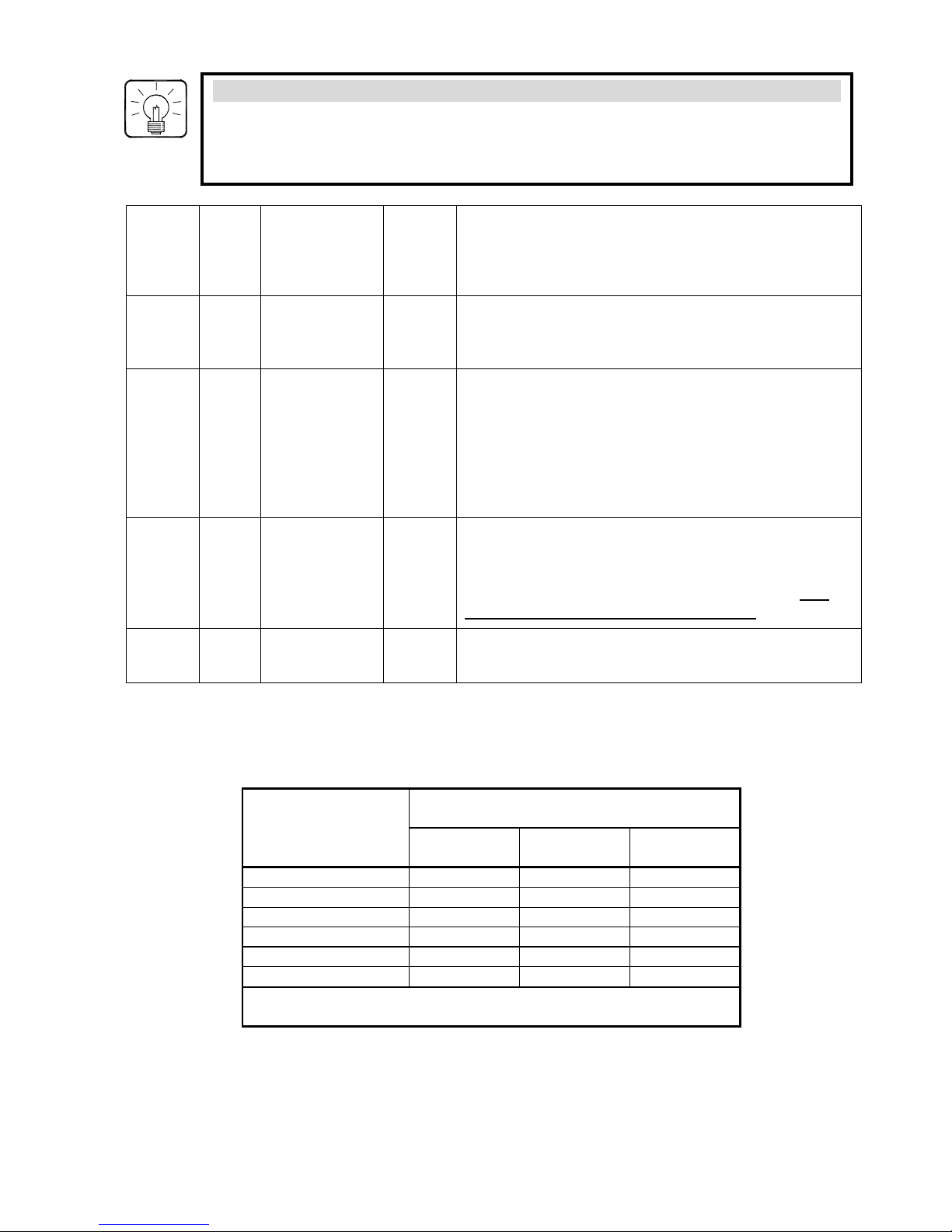
Controller Wiring
The following chart describes the function of each of the controller’s wires:
IMPORTANT: Make all controller wiring connections to the wiring harness before connecting the
harness to the vehicle.
Ord
er Color Function Wire
Size
(AWG)
Connect To
1st
White Ground 16 grounded metal part of the firewall or directly to the
negative (-) terminal of the battery. Connect this
wire first.
2nd
Black + connection
to the
vehicle’s
power system
12 positive (+) terminal of the battery. MUST have a
self-resetting Circuit Breaker in-line between the
controller and the battery. See chart for proper size.
Route the black wire through a grommet hole in the
fire wall to prevent wire grounding and away from the
radio antenna to reduce any possible AM radio
interference. Connect this wire second.
3rd
Red Stoplight 14 non-powered stop lamp wire (of the stop lamp switch)
or trailer tow wiring harness. It is recommended that
a 20-amp inline fuse be installed between the
controller’s red wire and the stop lamp switch. The
fuse is required in 1999 & later Fords.
4th Blue Output to
trailer brakes
12 the trailer brake wire or tow vehicle / trailer connector.
SELF-RESETTING CIRCUIT BREAKER
SIZE CHART
Number of Trailer Brakes
Number of Brake
Light Bulbs (tow
vehicle plus trailer)
2 Brakes 4 Brakes 6 Brakes
4 Bulbs (minimum) 20 AMP 30 AMP 30 AMP
5 Bulbs 20 AMP 30 AMP 30 AMP
6 Bulbs 20 AMP 30 AMP 40 AMP
7 Bulbs 30 AMP 30 AMP 40 AMP
8 Bulbs 30 AMP 30 AMP 40 AMP
9 Bulbs 30 AMP 40 AMP 40 AMP
Note: Each trailer brake magnet is assumed to draw 3 amps of
current and each brake lamp bulb is assumed to draw 2 amps.
TIP:
• Special Dual-Mated “Quik Connect
TM
” Wiring Harnesses are available for all Hayes
Brake Controllers fitted with a connector on the wire leads, making connection a
snap. Harnesses are available through all dealer resources. Ask specifically for the
Hayes Brake Controller Company (HBC) brand harnesses to match your controller.
Page 6
Special Conditions
For tow vehicles equipped with factory trailer towing package:
• Refer to your vehicle’s owner’s manual or other information provided by the manufacturer in
determining the correct connection points for the controller.
• See Appendix section for partial list of manufacturer wiring harness to controller conversions.
For vehicles without
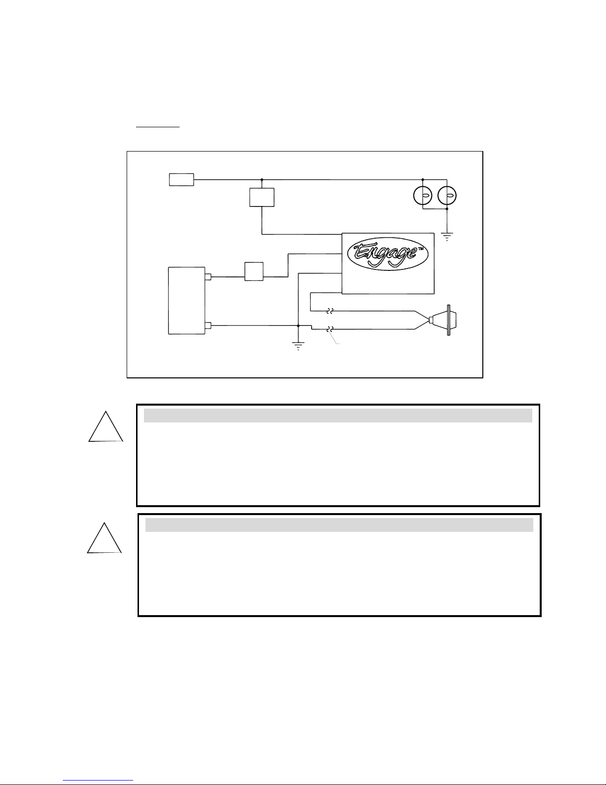
trailer-towing package: refer to the wiring diagram in Figure 4.
CHASSIS/GROUND
NON-POWERED STOPLIGHT WIRE
SELF-RESETTING
CIRCUIT BREAKER
(NOT FURNISHED)
SEE CHART FOR
SIZE
C.B.
POSITIVE
(+)
(-)
NEGATIVE
BATTERY
12 VOLT
20A
VEHICLE MECHANICAL
STOPLIGHT SWITCH
SW
BRAKE
CONTROLLER
TOW VEHICLE / TRAILER
ELECTRICAL CONNECTOR
TRAILER GROUND
TRAILER BRAKES
BLUE
GROUND
STOP LAMPS
20 AMP INLINE FUSE
(NOT FURNISHED)
WHITE
BLACK
RED
Figure 4 – Wiring Diagram
WARNING:
All 1999 and later Ford vehicles without the trailer wiring package:
• The re
d controller wire must be connected to the light green wire of the brake
stop lamp through a 20-amp inline fuse.
• Failure to install a 20-amp inline fuse can destroy the controller and void the
manufacturing warranty.
!
WARNING:
1989-1991 Ford Bronco, Ec
onoline, F-Superduty, and F150-350 Series:
• The red stoplight wire MUST splice into the turn signal connector harness and
NOT to the stoplight switch.
• Connecting to the terminal of the stoplight switch will break the switch and result
in no stoplights and no trailer braking.
!
Page 7
Appendix
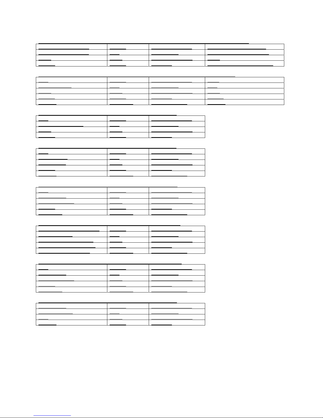
OEM TOW VEHICLE WIRING CONVERSION
CHRYSLER (THROUGH 2002) CONTROLLER FUNCTION CHRYSLER (NEW)
RED W/BLACK TRACE
BLACK +12 VOLT SUPPLY WHITE WITH RED TRACE
WHITE W/TAN TRACE RED STOPLIGHT BLUE WITH WHITE TRACE
BLUE BLUE TRAILER BRAKES BLUE
BLACK WHITE GROUND GREEN WITH BLACK TRACE
FORD (THROUGH 2002) CONTROLLER FUNCTION FORD (NEW)
RED
BLACK +12 VOLT SUPPLY PINK
LIGHT GREEN RED STOPLIGHT RED
BLUE BLUE TRAILER BRAKES BLUE
WHITE WHITE GROUND WHITE
BROWN NOT USED ILLUMINATION BROWN
FORD EXPEDITION CONTROLLER FUNCTION
RED
BLACK +12 VOLT SUPPLY
RED/GREEN TRACE RED STOPLIGHT
BLUE BLUE TRAILER BRAKES
BLACK WHITE GROUND
GENERAL MOTORS CONTROLLER FUNCTION
RED
BLACK +12 VOLT SUPPLY
LIGHT BLUE RED STOPLIGHT
DARK BLUE BLUE TRAILER BRAKES
BLACK WHITE GROUND
BROWN NOT USED ILLUMINATION
2004 INFINITY CONTROLLER FUNCTION
RED
BLACK +12 VOLT SUPPLY
RED/GREEN RED STOPLIGHT
BROWN/WHITE BLUE TRAILER BRAKES
BLACK WHITE GROUND
RED/BLUE NOT USED ILLUMINATION
RANGE ROVER CONTROLLER FUNCTION
REMOVE TAIL LIGHT AND
BLACK +12 VOLT SUPPLY
CONNECT RED RED STOPLIGHT
CONTROLLER WIRE TO BLUE TRAILER BRAKES
BLACK/BLUE TRACE, NO WHITE GROUND
LIGHT WITH MANUAL NOT USED ILLUMINATION
2004 TITAN/ARMADA CONTROLLER FUNCTION
RED
BLACK +12 VOLT SUPPLY
RED/GREEN RED STOPLIGHT
BROWN/WHITE BLUE TRAILER BRAKES
BLACK WHITE GROUND
RED/BLUE NOT USED ILLUMINATION
2004 TOYOTA TUNDRA CONTROLLER FUNCTON
BLACK-RED
BLACK +12 VOLT SUPPLY
GREEN-WHITE RED STOPLIGHT
RED BLUE TRAILER BRAKES
BROWN WHITE GROUND
Page 8
Electronic Brake Controller
Hayes Brake Controller Company P/N 81760
OPERATION MANUAL
For trailers with 2-6 electric brakes and vehicles with 12 volt negative ground systems only.
READ AND SAVE THESE INSTRUCTIONS
• Before beginning operation, read and become familiar with these instructions.
• Leave in tow vehicle for future reference.
• Improper installation and operation could cause personal injury and/or equipment and
property damage.
SAFETY INFORMATION
!
!
WARNING: Indicates a potentially hazardous situation that,
if not avoided, could result in death or serious, personal injury.
CAUTION: Indicates a potentially hazardous situation that,
if not avoided, could result in damage to product or property.
TIP: Contains helpful information to facilitate operation.
Page 9
Automatic Operation
During braking, the Engage operates on a time-based circuitry. The longer the brake pedal is
depressed, the greater amount of current delivered to the trailer brakes.
The “power ramp time” and power is adjustable to achieve trailer brake responsiveness.
The digital display will indicate the amount of power being sent to the trailer brakes.
Once the brake pedal is released, the unit will return to “stand by” mode. While in “stand by” mode, the
controller will display the currently selected mode of display (% power, voltage, or current).
A DETAILED EXPLANATION OF THESE MODES
IS INCLUDED IN THIS DOCUMENT.
DIGITAL DISPLAY
SETUP ADJUSTMENT
BUTTONS
MANUAL OVERRIDE
SLIDE LEVER
Figure 1 – Front View Engage Brake Controller
Page 10
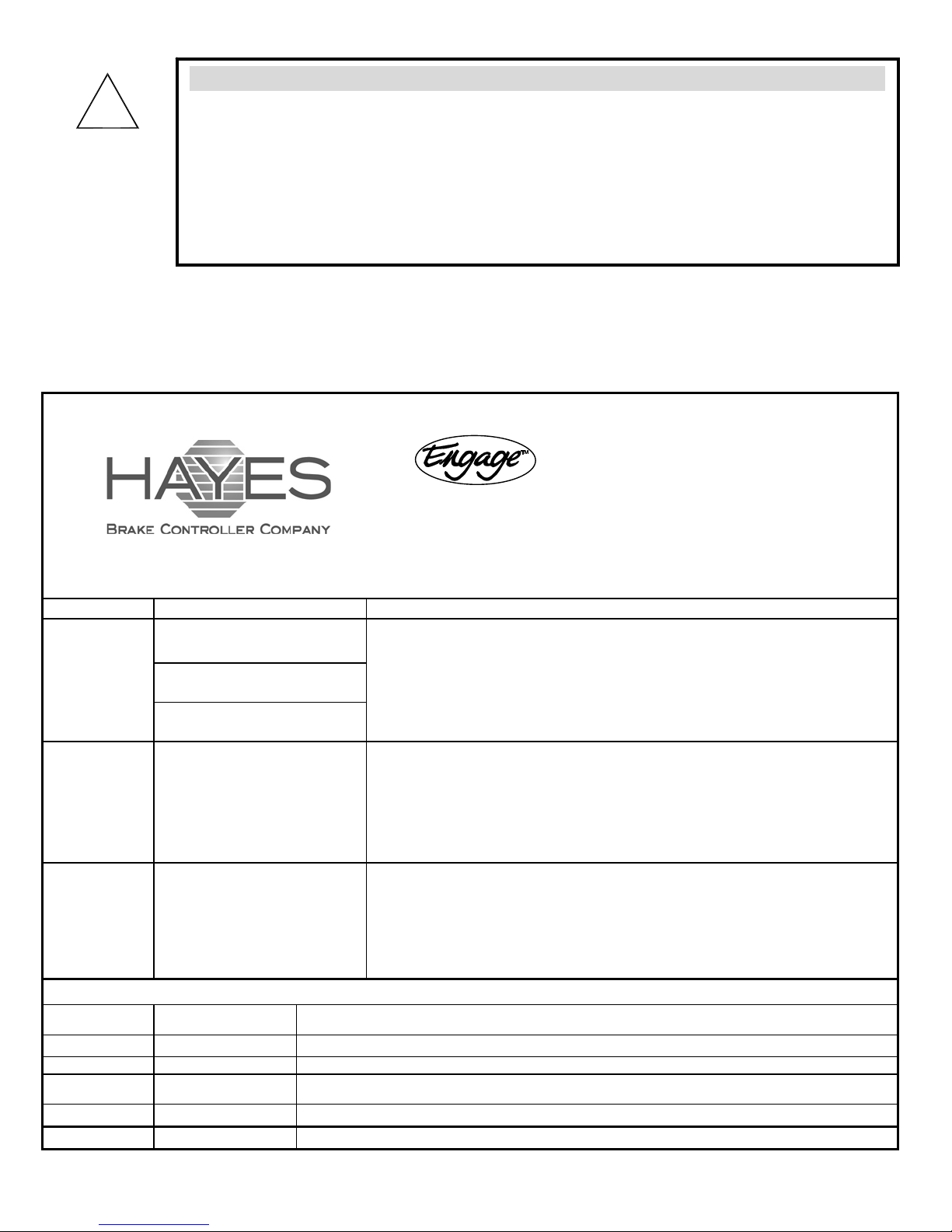
WARNING:
!
• Improper adjustment of the controller could result in loss of trailer brakes,
aggressive, grabby, pulsating, or delayed trailer brakes.
• Power adjustments may be required based upon speed, trailer load, and road
conditions.
• Maximum trailer braking occurs just prior to lockup of the trailer wheels.
• Trailer brake lockup could cause loss of control of the trailer and / or the tow
vehicle.
Controller Features and Settings
This controller features the following options, selections, and settings. Use illustration in Figure 1 to
assist in adjustment of settings.
Brake Controller
Item # 81760
Quick Reference
Option Available Selections Change procedure
Display Mode
(P is the default
mode. This mode
should be used
unless PH mode is
required.)
Power
Ramp Time
Maximum Power
(Automatic
Braking only)
(50% is the factory
default setting.)
P : % of available power being sent
to trailer brakes (PH for hydraulic
actuators)
E : Voltage (DC) being sent to trailer
brakes (EH for hydraulic actuators)
C : Current (DC) being applied to
trailer brakes (for
(seconds)
1
2
3
4
5
5% increments
10% to 100%. 100% is displayed as
setup only)
“99.”
•
Press “+” button
Display mode will flash (P, E, C, PH, or EH)
•
Press “+” button to cycle through optional display modes
•
When desired display mode is displayed, pr
•
release
The new display mode is now set
•
Note: PH or
•
•
•
•
•
•
•
•
•
•
•
EH display modes do not check for trailer connection and will not flash “OC”
Press “-” button until the display flashes and release
Power Ramp Time will flash (1, 2, 3, 4, or 5)
Press “-” button to cycle through optional settings
When desired time is displayed, press “+“ button until the flashing stops
The new Power Ramp Time is now set
The newly selected value will be displayed for a few seconds
After 15 seconds, the display will revert back to showing the display mode (P, E, C, PH, or
EH)
if no fur
Press “+” or “-“ button and release
The current power setting will be displayed
To raise the displayed power setting, press “+” button and release
To lower the displayed power setting, press “-“ butt
made for several seconds, the displayed power setting will be stored as the current
Maximum Power. The display will revert back to showing the display mode (P, E, C, PH, or
EH) and stores the last selected power setting
until the display flashes and release
ess “–“ button until the flashing stops and
ther selection is made
on and release. When no change is
The following is a list of potential trouble codes. Refer to the installation guide for complete explanation of the codes
Display Code Possible Cause
SC Short Circuit This indicates a direct short to ground in the blue wire (output) circuit
CL Current Limit Indicates that the brake controller is providing more than it’s maximum rated power
OC Open Circuit
HF Hazard Flash Will display while hazard flashers are on
bF Voltage on Blue Wire Blue wire connected to wrong place, short in wiring / connector, faulty or disconnected breakaway switch
Indicates that there is no trailer connection detected or the b
Actuated brakes
rake controller is connected to Electric/Hydraulic
Page 11

Definitions of Options
Display mode:
The controller is factory pre-set to display mode P (% of maximum power)
• During bra
brakes.
• It is recommended that display mode P (or PH for a hydraulic actuator) be used while operating the
vehicle.
PH mode also displays the % of power being applied to the trailer brakes. The scale for this is “0”-“99.”
Other available display modes:
• Voltage (E or EH) can be used in operation, but it should be noted that the actual voltage supplied to
the trailer br
• Current (C) reading can be used in troubleshooting and setup to ensure that the amperage draw of the
trailer brake
DO NOT
DO NOT
The current reading may vary significantly due to temperature swings in the brake magnets.
Changing Display Mode
The symbols (P, E, C, PH, or EH) that are displayed under normal braking conditions may be changed as follows:
1.
With the vehicle at rest, press the “+” button until the display flashes and release. The display will flash a letter,
which corresponds to the set display mode (P, E, C, PH, or EH).
2.
To change the set mode, press the “+” button and release. The display will change from P to E to C to PH to EH with
uential presses of the “+” butto
seq
3.
Continue pressing the “+” button until the desired display mode is shown on the display.
Press the “-“ button and hold until display stops flashing and release.
4.
The new display mode is now set.
5.
king conditions - the number displayed indicates the % of power being applied to the trailer
akes may vary from the
s is in the proper range based on th
displayed value by up to 1 Volt.
e number of axles on the trailer
use this setting while operating the vehicle. With the manual fully on, the brake coils
should draw approximately 3 amps each.
make current readings with the manual less than full on.
n.
Notes:
The P display mode is the factory default mode and is the recommended display mode. If the trailer has an
o
Electric over Hydraulic Actuator, the PH display mode is recommended.
o The PH and the EH display modes do not test for a trailer connection.
o After a few hours of being inactive (with a trailer connected), the display will go blank. While the display is
k, very little power will
blan
be used by the Engage.
Maximum Power (Automatic braking only):
The controller is factory pre-set to 50%. This means that approximately HALF of the power available through the vehicle’s
rging system can be applied to the brakes
cha
For Example, under automatic braking (via the brake pedal), the maximum power is the % of available power that is sent to
the trailer brakes upon completion of the Power Ramp Time.
Changing Maximum Power for automatic braking only
The maximum power may be changed from the default 50% value by doing the following:
NOTE: To change the power, the controller must be in “normal” operating mode. (i.e., displaying P, E, C, PH, or EH not
flashing)
1. With the vehicle at rest, press either the “+” or “-“ button momentarily and release. The set maximum power will be
ayed.
displ
2. While this maximum power value is displayed, press either the “+” (increase) or “-“ (decrease) button to make changes
to the power setting. The power percentage will change in increments of 5% with each sequential button push.
3.
The controller is instantly set to the newly displayed value.
When no button has been pressed for several seconds, the system will become idle and the display will change to
4.
Display mode (P, E, C, PH, or EH).
.
NOTE: when the value reaches 100%, the display will read “99.”
Page 12
Power Ramp Time:
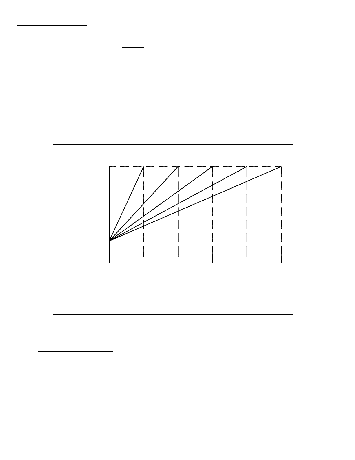
The controller applies power to the trailer brakes based on a time-based circuitry.
• The controller is factory pre-set to 3 seconds. - the number displayed indicates the selected
power ramp time to deliver power to the trailer brakes.
• When the Controller senses that the brake pedal has been depressed
o 10% of the available power is immediately applied to the trailer brakes.
o This power level continues to increase until it reaches a user-selectable setting (see
Changing Maximum Power section).
o Power Ramp Time - The elapsed time from the point that the brakes are first applied until
the point that the power level reaches its maximum
Power Ramp Time can be adjusted (1 - 5 seconds) to obtain optimum trailer
brake responsiveness between the tow vehicle brakes and the trailer brakes.
Figure 2 illustrates the effect of varying Power Ramp Time vs. the controller’s
output.
Set Power
Power Ramp Time Options
Level
10%
Power Level
0
12 4
3
Ramp Time (seconds)
Figure 2 – Engage Power Ramp Time Chart
5
Changing Power Ramp Time
1. With the vehicle at rest, press the “-” button until the display flashes and release. The display will
flash a number, which corresponds to the set Power Ramp Time (seconds).
2. To change the set value, press the “-” button and release. The display will change to the next
highest available value with sequential presses of the “-” button.
3. Continue pressing the “-” button until the desired Power Ramp Time value is displayed. The range
is 1 to 5 seconds.
4. Press the “+“ button and hold until the display stops flashing.
5. The new Power Ramp Time is now set.
NOTE: when the value reaches 100%, the display will read “99.”
Page 13
Manual Operation
WARNING:
!
• The “Manual Slide Lever” (Figure 1) is located on the front right side of the controller.
• The further the manual slide lever is moved from the right to the left, the greater the amount of
trailer braking effort.
• The manual slide lever operation is an independent circuit and overrides the maximum power
adjustment to allow full braking effort when required.
• Manual Slide Lever is used to apply the trailer brakes independently of the tow vehicle brakes or to
override the automatic trailer brakes when more or less braking is required.
• The manual slide lever is used in emergency stop situations when more braking may be required
than is available with the power wheel adjustment or for control of excessive trailer sway.
• The tow vehicle and trailer brake stoplights will be illuminated during the manual lever activation.
Manual operation via the manual slide lever may not disengage the Cruise Control
on some vehicles.
TIP:
It is normal to hear the trailer brake magnets “hum” when operating the trailer brakes.
Troubleshooting using the manual slide
To verify the brake controller is properly wired, follow these steps:
A. Disconnect the tow vehicle/trailer electrical connector. Set the display mode to PH. Move the
manual slide lever (Figure 1) to the left. The displayed value should increase and the tow vehicle
stop lamps must illuminate.
B. If SC is displayed, the tow vehicle has a short to ground in the trailer brake circuit or the white
ground wire is not connected to ground. Check and/or repair wiring and tow vehicle/trailer
connector.
C. If the stop lamps do not illuminate, check the red stoplight wire connection of the brake controller
for connections to the non-powered stop lamp wire of the vehicle stop lamp switch. Set the display
mode to P if trailer does not have electric/hydraulic brakes.
D. Connect the tow vehicle/trailer electrical connector.
E. If the display flashes OC, check and repair blue wire connections and brake coil connections. The
controller does not see a brake coil connection.
F. Move the manual lever to the left. The displayed value should increase and the trailer stop lamps
must illuminate.
G. If SC or CL is displayed, check the trailer brake magnets and trailer brake circuit (including the tow
vehicle/trailer connector) for a short to ground.
H. If the trailer stop lamps do not illuminate, check and repair trailer wires, bulbs, bulb ground
connections, and the tow vehicle/trailer connector.
I. Also check the red stop light wire connection of the brake controller for connections to the non-
powered stop lamp wire of the vehicle stop lamp switch.
Page 14
Road Test and Performance Adjustment
To set the controller up for optimum performance with your tow vehicle / trailer combination,
follow these steps:
A. Position vehicle on a hard, flat, dry surface.
B. Set the display mode to % (P or PH for Hydraulic brakes). See “Changing Display Mode” section.
C. Adjust the power setting to 50%. See “Changing Maximum Power” section.
D. Accelerate to approximately 25 mph and apply the brakes in a normal manner. The vehicle should
come to a stop without the trailer “pushing” the tow vehicle. A firm braking action should occur.
E. If the trailer brakes lock, decrease the power.
F. If more braking power is needed, increase the power.
G. Repeat this process until the desired amount of braking is achieved.
H. If needed, follow the instructions in ”Changing Power Ramp Time” section to increase or decrease
the Power Ramp Time.
There are two methods of adjusting the output and responsiveness of your Engage Brake Controller.
They are listed here in the order in which they should be modified:
1. Power Adjustment:
The power is adjustable from 10% to 100%. This figure is based on the amount of power available for delivery
to the trailer
vehicle’s charging system.
Power Ramp Time Adjustment:
2.
As described earlier in this document, this is the amount of time the controller takes to raise the output from
10% to the
brakes. The total amount of power available is determined by the size and condition
user-selected Maximum Power level.
of the
TIP:
• Warm trailer brakes tend to be more responsive than cold brakes.
Page 15
Troubleshooting using the display
The Digital Display will “flash” a symbol to indicate a problem with the trailer, the tow vehicle, or the brake
controller.
Short Circuit:
The display will flash “SC”. This indicates that the controller has sensed a direct short between the
controller’s output and ground. This condition must be cleared before the controller is used. It is
usually an indication that a “hot” wire is connected to ground.
Current Limit:
The display will flash “CL”. This indicates that the controller has sensed a power requirement greater
than its recommended output. When this occurs, the controller will continue to supply all of the needed
current (up to approximately 24 amps). This could result from an intermittent short to ground in the
trailer wiring, a faulty brake coil, or too many brake coils connected to the controller.
Open Circuit:
The display will flash “OC”. This is an indication that there is no trailer connected to the tow vehicle.
Flashing “OC” will display for a few minutes or until a trailer is connected to the tow vehicle.
Connection to electric over hydraulic trailer brakes can also cause the display to flash “OC”. The
display will go blank when no load is detected for several minutes.
TIP:
If a trailer with electric over hydraulic brakes is connected and “OC” is
•
flashing, change the display mode to PH or EH. PH is recommended.
TIP:
• If “OC” is flashing (with no trailer connected), the display will turn-off after
several minutes.
TIP:
• During the time that the controller senses the Hazard Flash, no power will
be sent to the trailer brakes. Therefore, there should be no pulsing of the
brakes.
Hazard Flash:
The display will flash “HF”. This occurs when the controller senses a distinct cycling of power in the
brake light circuit. The controller will continue to display “HF” until the cycle is broken either by a
braking event or by a discontinuation of the power cycling.
Blue Wire Fault:
The display will flash “bF”. This occurs when external voltage is detected on the blue wire. The
controller will continue to display “bF” until external voltage is removed. Possible causes can be the
blue wire being connected to the wrong place, a short in the wiring or the connector, or a faulty or
disconnected breakaway switch.
Page 16
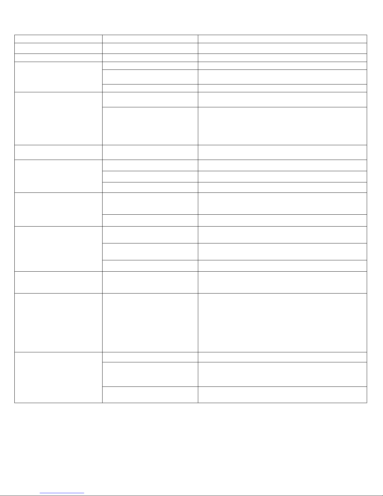
Troubleshooting
Symptom Possible Cause Remedy
Trailer Brakes “Lock Up”. Power set too high. Reduce maximum power setting.
Low output to trailer brakes. Power set too low. Increase maximum power setting.
Weak / Ineffective Brakes.
(manual or automatic).
No output to trailer brakes
(automatic only).
Intermittent or surging
brakes.
display reads “SC” when
brakes are applied.
Overloaded trailer. Check weight rating.
Loose or poor quality.
Connections.
Insufficient wire gauge Inspect / replace.
Improper Wiring. Check color codes of all wires. No output to trailer brakes
Improperly grounded. Ensure that the following are grounded:
Faulty Brake Light Circuit on
tow vehicle.
Improperly grounded. Check and repair all ground connections.
Out of Round brake drums. Repair / replace.
Worn wheel bearings. Repair / replace.
Direct short to ground either in
tow vehicle wiring or in trailer
wiring.
Faulty brake magnets. Test / replace brake magnets.
Inspect connections / check with meter.
•
Controller (white wire).
•
Tow vehicle connector.
•
Trailer umbilical cord.
•
Each brake magnet.
Troubleshoot / repair brake light circuit.
Inspect and repair wiring. No output to trailer brakes,
Reduced output to trailer
brakes, display reads “CL”
when brakes are applied.
Trailer brakes lockup when
trailer connector and cable is
attached.
Controller displays flashing
“bF”.
Controller displays flashing
“OC”.
Note: If the display mode is
set to PH or
controller will not check for a
trailer connection and will not
flash “OC”.
EH, the
Too many brake magnets are
attached to controller.
Intermittent short to ground in
tow vehicle or trailer wiring.
Defective brake magnets. Test / replace brake magnet s.
Faulty break-away switch. Test / replace switch.
Indicates presence of an
unexpected 12 Volts on the
blue (output) wire due to one of
the following:
• • Faulty wiring.
Malfunctioning or
nected break-away
discon
swit
ch.
No trailer connected. Flashing will stop in a few minutes.
Trailer with Electric over
Hydraulic brakes.
Blue controller wire not
connec
ted to c
rrect wire.
o
Controller only handles 1-3 axles with brakes.
Inspect and repair wiring.
Inspect wiring and break-away switch. Ensure that there
is no voltage on the blue wire when the bra
depressed.
Change Display mode to PH or EH.
Note: These two modes do not check for a trailer
connec
Inspect wiring and repair.
tion.
ke pedal is not
Feel the difference with Hayes.
Learn more about trailer hitches and towing we have.
 Loading...