

Page 1

Operating Instructions and Parts Reference
TM
2574
BALEBUSTER
0500158 • August 2020
Product InformatIon
DuraTech InDusTrIes InTernaTIonal Inc.
Po Box 1940, Jame sTown, nD 58402-1940
Tel: (701) 252-4601• Fax: (701) 252-0502
www.DuraTechInDusTrIes.neT • www.hayBusTer.com
Page 2

A Tradition of Innovation Since 1966
Page 3

TM
2574
BALEBUSTER
Operating Instructions
and Parts Reference
TM
DuraTech Industries International Inc.(DuraTech Industries) has made every effort to assure that
this manual completely and accurately describes the operation and maintenance of the 2574™
BALEBUSTER™ as of the date of publication. DuraTech Industries reserves the right to make
updates to the machine from time to time. Even in the event of such updates, you should still nd
this manual to be appropriate for the safe operation and maintenance of your unit.
This manual, as well as materials provided by component suppliers to DuraTech Industries are
all considered to be part of the information package. Every operator is required to read and
understand these manuals, and they should be located within easy access for periodic review.
& are registered trademarks of Duratech Industries
International, Inc. 2574 and Balebuster are trademarks of Duratech Industries International, Inc.
STRAW CANNON® and logo are registered trademarks of Duratech Industries International, Inc.
Page 4

A Tradition of Innovation Since 1966
Page 5
FOREWORD
Foreword
All personnel must read and understand the following sections before operating the
BALEBUSTER™.
• Section 2, ”Dealer Preparation,” to verify that the machine has been prepared for
use.
• Section 3, “Operation,” which explain normal operation of the machine.
• Foreword and Section 1, important safety information.
• Section 3.1, “Pre-Operation Inspection”.
Appropriate use of unit
Your model 2574™ BALEBUSTER™ is designed to load and shred most types of
baled livestock forage. It is designed specically for use on 6 foot. diameter round
bales weighing up to 2,000 pounds and 5-1/2 feet in length
To avoid possible damage to the machine and risk of injury to the operator, consult
with a DuraTech representative before attempting to shred materials other than
livestock forage.
The BALEBUSTER has multiple uses:
• Laying forage windrows in open elds.
• Filling feed bunks - fenceline, circular etc.
• Spreading straw for livestock bedding.
• Spreading mulch over perennial plants, such as strawberries, mushrooms, etc.
• Spreading mulch over reclaimed land areas.
• Spreading mulch over sugar beets for storage.
2574 BALEBUSTER OPERATING INSTRUCTIONS
i
Page 6

Operator protection
As with all machinery, care needs to be taken in order to insure the safety of the
operator and those in the surrounding area.
WARNING: The OPERATOR IS RESPONSIBLE for the safety of the
operator and those in the surrounding area. Operators of the BALEBUSTER
are required to wear head, eye, and ear protection, No loose clothing is
allowed.
ii
2574 BALEBUSTER OPERATING INSTRUCTIONS
Page 7

TABLE OF CONTENTS
Part 1: Operating Instructions .........................................2
Introduction ...................................................................................... 2
Appropriate use of unit ............................................................... 2
Purpose ....................................................................................... 2
How to use this manual ............................................................... 3
Section 1: Safety ......................................................................... 4
1.1 Safety-alert symbols ........................................................................................ 4
1.2 Operator - personal equipment ...................................................................... 6
1.3 Machine safety labels ...................................................................................... 7
1.4 Shielding ........................................................................................................... 9
1.5 Personal equipment ........................................................................................ 9
1.6 Safety review ................................................................................................... 9
1.7 Towing/road transport .................................................................................. 11
Section 2: Dealer preparation .................................................. 12
2.1 Assembly required ......................................................................................... 12
2.2 Pre-delivery inspection .................................................................................. 12
2.3 Machine operation check .............................................................................. 13
2.4 Loader tines.................................................................................................... 14
Section 3: Operation ................................................................. 15
3.1 Pre-operation inspection ............................................................................... 16
3.2 Introduction to the machine ....................................................................... 17
3.2.1 Operator controls .......................................................................................... 17
3.2.2 Bale conveyor ............................................................................................... 17
3.2.3 Rotor ............................................................................................................. 17
3.2.4 Auger ............................................................................................................ 18
3.2.5 Slug bars ....................................................................................................... 18
3.2.6 Screen ........................................................................................................... 18
3.2.7 Fan ................................................................................................................ 18
3.2.8 Discharge spout and deector ...................................................................... 18
3.3 Machine Operation & Adjustments ........................................................... 19
3.3.1 Tractor Set Up .............................................................................................. 19
3.3.2 Hitching the BALEBUSTER to a tractor ..................................................... 20
3.3.2A Movable Hitch .................................................................................20
3.3.3 Starting the machine ....................................................................................21
3.3.4 Normal shut-down procedure ......................................................................22
3.3.5 Unhitching the BALEBUSTER from a tractor ...........................................22
2574 BALEBUSTER OPERATING INSTRUCTIONS
iii
Page 8

TABLE OF CONTENTS
3.3.6 P.T.O. Shield and Belt Access Cover .........................................................23
3.3.7 Conveyor Chain Adjustment ......................................................................24
3.3.8 Adjusting Belt Tension ...............................................................................25
3.3.9 Slugbar Adjustment ....................................................................................26
3.3.10 Clean Out Door .........................................................................................27
3.3.11 Flails..........................................................................................................27
3.3.12 Loader .......................................................................................................28
3.3.13 Loading the bale .......................................................................................30
3.3.14 Operating the machine ..............................................................................31
3.3.15 Loader Transport Pin ................................................................................31
3.3.16 Hydraulic Cylinder and Valve ..................................................................31
3.3.18 Rack ..........................................................................................................32
3.3.17 Tires and Rims ..........................................................................................32
3.3.18A Rack Tool .......................................................................................33
3.3.19 Jack ...........................................................................................................34
3.3.20 Hooking up hydraulic control box and hydraulics to tractor ....................34
3.3.21 Fan ............................................................................................................35
3.4 Adjusting the machine ...............................................................................36
3.4.1 Changing the output distribution pattern ....................................................36
3.4.2 Changing length of cut ................................................................................37
3.4.3 Changing screens ........................................................................................37
3.4.4 Adjusting the bale conveyor speed ..............................................................37
3.4.5 Changing the slug bar settings ....................................................................38
3.5 Road transport ..........................................................................................38
3.5.1 Preparing the BALEBUSTER for transport ................................................38
3.5.2 Changing Back To Operate .........................................................................39
3.6 Storage .........................................................................................................39
3.6.1 Preparing the machine for storage ...............................................................39
3.6.2 Removing the machine from storage ...........................................................40
Section 4: General maintenance ............................................. 41
4.1 Lubrication .................................................................................................41
4.1.1 LUBRICATION POINTS ............................................................................41
iv
4.2 Axle, wheels, tires .........................................................................................48
4.3 Conveyor chain tension ..............................................................................48
4.4 Belt Bushing Torque Settings ......................................................................48
4.5 General appearance .....................................................................................48
2574 BALEBUSTER OPERATING INSTRUCTIONS
Page 9

TABLE OF CONTENTS
Section 5: Troubleshooting ..................................................... 49
Appendix A: WARRANTY ......................................................... 50
Appendix B: 2574 BALEBUSTER Specications .................... 51
Appendix C: Options ............................................................... 52
Appendix D: Required For Operation ...................................... 53
Appendix E: 2574 BALEBUSTER SHIPPING LIST ................... 54
Part 2: Parts Reference ..................................................55
MAIN FRAME ASSEMBLY ................................................................................. 56
MAIN FRAME ASSEMBLY ................................................................................. 57
MAIN FRAME ASSEMBLY - DETAIL A ............................................................ 58
3600838 PTO ......................................................................................................... 60
3600839 PTO ......................................................................................................... 62
FAN ASSEMBLY .................................................................................................. 64
FAN ASSEMBLY - DETAILS A AND B .............................................................. 66
FAN ASSEMBLY - REPLACEABLE FIN AND SHAFT .................................... 68
DRIVE ASSEMBLY .............................................................................................. 70
SHREDDER ASSEMBLY FRONT ....................................................................... 72
SHREDDER ASSEMBLY - SHIELDS, DOOR, & SCREEN .............................. 74
AUGER ASSEMBLY ............................................................................................. 76
ROTOR ASSEMBLY ............................................................................................. 78
SLUG BAR ASSEMBLY ....................................................................................... 80
CONVEYOR ASSEMBLY .................................................................................... 82
RACK ASSEMBLY ............................................................................................... 84
LOADER ASSEMBLY .......................................................................................... 86
WHEEL AND BEARING ASSEMBLY ................................................................ 88
HYDRAULIC ASSEMBLY - DETAILS A AND B (THRU S.N. 0051) ............... 90
HYDRAULIC ASSEMBLY - DETAILS C AND D (THRU S.N. 0051) .............. 91
HYDRAULIC ASSEMBLY - DETAILS E,F AND G (THRU S.N. 0051) ........... 92
HYDRAULIC ASSEMBLY (THRU S.N. 0051) ................................................... 93
HYDRAULIC ASSEMBLY - DETAILS A AND B (S.N. 0052 AND UP) ........... 94
HYDRAULIC ASSEMBLY - DETAILS C AND D (S.N. 0052 AND UP) ........... 95
HYDRAULIC ASSEMBLY - DETAILS E,F AND G (S.N. 0052 AND UP) ........ 96
HYDRAULIC ASSEMBLY (S.N. 0052 AND UP) ............................................... 97
HYDRAULIC SCHEMATIC ................................................................................. 99
HYDRAULIC VALVE - 4000569 ....................................................................... 100
HYDRAULIC VALVE - 4000569 WIRE LAYOUT ........................................... 102
2574 ELECTRICAL SCHEMATIC ..................................................................... 103
2574 BALEBUSTER OPERATING INSTRUCTIONS
v
Page 10

TRACTOR / IMPLEMENT WIRING HARNESS .............................................. 104
5701079 TAILLIGHT HARNESS ....................................................................... 105
FLOW CONTROL VALVE (4000331) ............................................................... 106
FLOW CONTROL VALVE ................................................................................. 107
JOYSTICK CONTROL BOX .............................................................................. 108
ORBIT MOTOR ASSEMBLY ..............................................................................111
OPTIONAL COVERED SPOUT ASSEMBLY ................................................... 112
OPTIONAL 5-1/2 FT. STRAW CANNON ASSEMBLY .................................... 114
SPOUT OPTIONS ............................................................................................... 116
FLOTATION TIRE (OPTION) ............................................................................ 118
AXLE EXTENSIONS (OPTION) ....................................................................... 120
OPTIONAL 2ND AXLE (HIGHWAY TIRES ONLY) ........................................ 122
OPTIONAL SHREDDER EXTENSION ASSEMBLY ....................................... 124
OPTIONAL CONTAINMENT ASSEMBLY ....................................................... 126
TAILLIGHTS - STANDARD MOUNTING ....................................................... 128
OPTIONAL HYDRAULIC SLUG BAR ............................................................. 130
DECALS .............................................................................................................. 132
DECAL LOCATIONS ......................................................................................... 134
2574 BALEBUSTER DOCUMENTATION COMMENT FORM ....... 139
vi
2574 BALEBUSTER OPERATING INSTRUCTIONS
Page 11

TM
2574
BALEBUSTER
Part 1:
TM
Operating Instructions
2574 BALEBUSTER OPERATING INSTRUCTIONS
1
Page 12

Introduction
Appropriate use of unit
Your model 2574™ BALEBUSTER™ is designed to load and shred most types of baled livestock forage. It is
designed specically for use on 6 foot. diameter round bales weighing up to 2,000 pounds and 5-1/2 feet in length
NOTE: To avoid possible damage to the machine and risk of injury to the operator, consult with
a DuraTech Industries International, Inc. (DuraTech Industries) representative before attempting to
shred materials other than livestock forage.
The 2574 BALEBUSTER has multiple uses:
• Laying forage windrows in open elds.
• Filling feed bunks - fenceline, circular etc.
• Spreading straw for livestock bedding.
• Spreading mulch over perennial plants, such as strawberries, mushrooms, etc.
• Spreading mulch over reclaimed land areas.
• Spreading mulch over sugar beets for storage.
Purpose
The purpose of this owner’s manual is to explain maintenance requirements and routine adjustments for the most
efcient operation of your 2574 BALEBUSTER. There is also a trouble shooting section that may help in case of
problems in the eld. Any information not covered in this manual may be obtained from your dealer.
SPECIAL NOTE: When reference is made as to front, rear, left hand, or right hand of
this machine, the reference is always made from standing at the rear end of the machine
and looking toward the hitch. Always use serial number and model number when referring
to parts or problems. Please obtain your serial number and write it below for your future
reference.
MODEL: 2574 BALEBUSTER SERIAL NO. ________________________
2
2574 BALEBUSTER OPERATING INSTRUCTIONS
Page 13

How to use this manual
Manual organization
This manual is organized into the following parts:
• Part 1: Operating instructions explain how to set up, use and maintain the 2574 BALEBUSTER.
• Part 2: Parts reference contains diagrams of each assembly, with the part number of each part. A key on
the facing page contains a description of the part and the quantity used.
Dealer responsibilities
• Read Section 2, “Dealer Preparation,” and perform the tasks outlined. Also perform a pre-operation
inspection as described in Section 3.1.
• Upon delivery of the unit to the customer, it is your responsibility to conduct a training session on the safe
operation of the unit for the primary operator(s). You must also conduct a “walk-around” inspection of all
safety instructional decals on the machine itself. Decals are illustrated in Part 2: Parts Reference.
• Complete and return the Warranty Registration Card. Receipt of this form is required to activate the
warranty. Appendix A provides details of the warranty.
Operator responsibilities
• Operator is responsible for his safety.
• Operator is also responsible for safety of others near the machine.
• Review Section 2, ”Dealer Preparation,” to verify that the machine has been prepared for use.
• Thoroughly review sections 1 and 3, which explain normal operation of the machine, and section 4,
which explain maintenance requirements.
• Note the important safety information in the Foreword and in Section 1, “Safety.”
• Keep copies of all manuals in a readily - accessible location for future reference.
• Tractor is setup according to section 3.3.1 “tractor set-up”
2574 BALEBUSTER OPERATING INSTRUCTIONS
3
Page 14
Section 1: Safety
The safety of the operator is of great importance to DuraTech Industries/Haybuster. We have provided decals, shield
and other safety features to aid you in using your machine safely. In addition, we ask you to be a careful operator who
will properly use and service your Haybuster equipment.
WARNING: FAILURE TO COMPLY WITH SAFETY INSTRUCTIONS THAT FOLLOW
WITHIN THIS MANUAL COULD RESULT IN SEVERE PERSONAL INJURY OR DEATH.
BEFORE ATTEMPTING TO OPERATE THIS MACHINE, CAREFULLY READ ALL
INSTRUCTIONS CONTAINED WITHIN THIS MANUAL. ALSO READ THE INSTRUCTION
MANUAL PROVIDED WITH YOUR TRACTOR.
THIS MACHINE IS NOT TO BE USED FOR ANY PURPOSE OTHER THAN THOSE
EXPLAINED IN THE OPERATOR’S MANUAL, ADVERTISING LITERATURE OR
OTHER DURATECH INDUSTRIES WRITTEN MATERIAL PERTAINING TO THE 2574
BALEBUSTER.
1.1 Safety‑alert symbols
Decals are illustrated in Part 2: Parts Reference.
The safety decals located on your machine contain important and useful information that will help you operate your
equipment safely.
To assure that all decals remain in place and in good condition, follow the instructions below:
• Keep decals clean. Use soap and water - not mineral spirits, adhesive cleaners and other similar cleaners
that will damage the decal.
• Replace all damaged or missing decals. When attaching decals, surface temperature of the machine must
be at least 40° F (5° C). The surface must be also be clean and dry.
• When replacing a machine component to which a decal is attached, be sure to also replace the decal.
• Replacement decals can be purchased from your Haybuster dealer.
DuraTech Industries uses industry accepted ANSI or ASAE standards in labeling its products for safety and operational
characteristics.
Safety‑Alert Symbol
Read and recognize safety information. Be alert to
the potential for personal injury when you see this
safety-alert symbol.
4
2574 BALEBUSTER OPERATING INSTRUCTIONS
Page 15

DANGER: Indicates an imminently
hazardous situation that, if not avoided, will
result in death or serious injury. This signal
word is to be limited to the most extreme
situations, typically for machine components
that, for functional purposes, cannot be
guarded.
WARNING: Indicates a potentially hazardous
situation that, if not avoided, could result in
death or serious injury, and includes hazards
that are exposed when guards are removed.
It may also be used to alert against unsafe
practices.
CAUTION: Indicates a potentially hazardous
situation that, if not avoided, may result in
minor or moderate injury. It may also be used
to alert against unsafe practices.
This manual uses the symbols to the right to denote
important safety instructions and information.
The DANGER, WARNING and CAUTION symbols
are used to denote conditions as stated in the text above.
Furthermore, the text dealing with these situations is
surrounded by a box with a white background, will begin
with DANGER, WARNING, or CAUTION.
The INFORMATION symbol is used to denote important
information or notes in regards to maintenance and use of
the machine. The text for this information is surrounded
by a box with a light grey background, and will begin with
either IMPORTANT or NOTE.
DANGER
WARNING
CAUTION
INFORMATION
2574 BALEBUSTER OPERATING INSTRUCTIONS
5
Page 16

1.2 Operator ‑ personal equipment
THE OPERATOR
Physical Condition
You must be in good physical condition and mental health and not under the inuence of any substance (drugs, alcohol)
which might impair vision, dexterity or judgment.
Do not operate a 2574 BALEBUSTER when you are fatigued. Be alert - If you get tired while operating your
2574 BALEBUSTER, take a break. Fatigue may result in loss of control. Working with any farm equipment can
be strenuous. If you have any condition that might be aggravated by strenuous work, check with your doctor before
operating
Proper Clothing
Clothing must be sturdy and snug-tting, but allow complete freedom of movement.
Avoid loosetting jackets, scarfs, neckties, jewelry, ared or cuffed pants, unconned long
hair or anything that could become entangled with the machine.
Protect your head with a hard hat to reduce the risk of injury from ying debris.
Protect your hands with gloves when handling ail and sections. Heavyduty, nonslip
gloves improve your grip and protect your hands.
Good footing is most important. Wear sturdy boots with nonslip soles. Steel-toed safety
boots are recommended.
To reduce the risk of injury to your eyes never operate a 2574 BALEBUSTER unless
wearing goggles or properly tted safety glasses with adequate top and side protection.
Tractor noise may damage your hearing. Always wear sound barriers (ear plugs or ear
mufers) to protect your hearing. Continual and regular users should have their hearing
checked regularly.
6
2574 BALEBUSTER OPERATING INSTRUCTIONS
Page 17
1.3 Machine safety labels
The safety decals located on your machine contain important information that will help you operate your equipment.
Become familiar with the decals and their locations.
DANGER: FLYING HAY, ROCKS, AND OTHER
OBJECTS THROWN BY MACHINE.
STAY CLEAR OF DISCHARGE SIDE OF MACHINE
UNLESS OPERATOR HAS STOPPED TRACTOR
ENGINE AND MACHINE HAS STOPPED ROTATING.
FAILURE TO FOLLOW THESE INSTRUCTIONS MAY
RESULT IN SEVERE PERSONAL INJURY OR DEATH.
DANGER: ROTATING FLAILS CAN KILL OR
DISMEMBER
KEEP CLEAR OF MACHINE UNTIL POWER TAKE‑OFF
HAS BEEN DISENGAGED, TRACTOR ENGINE SHUT
OFF AND FLAIL ROTATION STOPPED
6500034
6500035
DANGER: ROTATING DRIVELINE, KEEP AWAY!
ENTANGLEMENT CAN CAUSE SERIOUS INJURIES OR
DEATH.
DO NOT OPERATE WITHOUT
• ALL DRIVELINE GUARDS, TRACTOR AND
EQUIPMENT SHIELDS IN PLACE
• DRIVELINES SECURELY ATTACHED AT BOTH
ENDS
• DRIVELINE GUARDS THAT TURN FREELY ON
DRIVELINE
DANGER: ROTATING PARTS WITHIN CAN KILL OR
DISMEMBER. WAIT FOR ALL MOVEMENT TO STOP
BEFORE SERVICING, UNLOADING, OR INSPECTING
MACHINE.
6500085
6500082
2574 BALEBUSTER OPERATING INSTRUCTIONS
7
Page 18
WARNING: FOR YOUR PROTECTION KEEP ALL
SHIELDS IN PLACE AND SECURED WHILE MACHINE
IS OPERATING MOVING PARTS WITHIN CAN CAUSE
SEVERE PERSONAL INJURY.
WARNING: FOR YOUR PROTECTION AND
PROTECTION OF OTHERS, PRACTICE THE
FOLLOWING SAFETY RULES.
1. BEFORE OPERATING THIS MACHINE, READ THE
OPERATOR’S MANUALS SUPPLIED WITH THIS
MACHINE AND YOUR TRACTOR.
6500040
2. CHECK OPERATORS MANUALS TO BE SURE
YOUR TRACTOR MEETS THE MINIMUM
REQUIREMENTS FOR THIS MACHINE.
3. READ ALL DECALS PLACED ON THIS MACHINE
FOR YOUR SAFETY AND CONVENIENCE.
4. NEVER ALLOW RIDERS ON THIS IMPLEMENT OR
THE TRACTOR.
5. KEEP OTHERS AWAY FROM THIS MACHINE
WHILE IN OPERATION.
6. KEEP ALL SHIELDS IN PLACE WHILE MACHINE IS
OPERATING.
7. KEEP HANDS, FEET, LOOSE CLOTHING, ETC.,
AWAY FROM POWER DRIVEN PARTS.
8. ALWAYS SHUT OFF MACHINE AND ENGINE
BEFORE SERVICING, UNCLOGGING,
INSPECTING, OR WORKING NEAR THIS MACHINE
FOR ANY REASON. ALWAYS PLACE
TRANSMISSION IN PARK OR SET PARK BRAKE
AND WAIT FOR ALL MOVEMENT TO STOP
BEFORE APPROACHING THIS MACHINE.
6500041
WARNING:
• RISK OF HEAD AND EYE INJURIES.
• RISK OF HEARING DAMAGE.
HEAD, EYE, AND HEARING PROTECTION REQUIRED.
6500549
WARNING: Moving parts can crush and cut.
Keep hands clear.
6500488
8
2574 BALEBUSTER OPERATING INSTRUCTIONS
Page 19
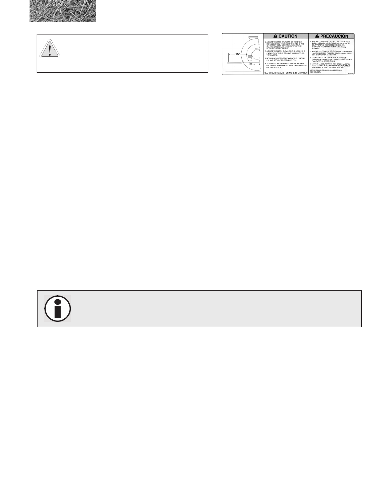
CAUTION: ADJUST TRACTOR DRAWBAR SO THAT
THE DISTANCE FROM THE END OF THE P.T.O.
SHAFT ON THE TRACTOR TO THE CENTER OF THE
DRAWBAR HITCH PIN IS 16”.
6500322
• Replacement decals can be purchased from your Haybuster dealer.
1.4 Shielding
Shields are installed for your protection. Keep them in place, and replace damaged shields.
1.5 Personal equipment
Operators of this machine are encouraged to wear head, eye, and ear protection. Operators should not wear loose
clothing.
1.6 Safety review
BEFORE OPERATING THE MACHINE
• Read and follow all instructions contained in:
A. This 2574 BALEBUSTER Operator’s manual
B. Tractor Operator’s manual
C. Decals placed on the 2574 BALEBUSTER
NOTE: Additional copies of the above mentioned materials can be obtained from your dealer.
• Allow only responsible, properly instructed individuals to operate your machine. Carefully supervise
inexperienced operators.
• Use a tractor which meets the tractor requirements contained within this manual. See Appendix D.,
Required For Operation:
• Make sure the machine is in good operating condition and that all protective shields are in place and in
proper working order. Replace damaged shields before operating.
• Make no modications to the machine unless specically recommended or requested by DuraTech
Industries.
• Check periodically for broken or worn parts and make any necessary repairs.
• If required install the PTO safety chain. Check local regulations regarding safety chain requirements.
2574 BALEBUSTER OPERATING INSTRUCTIONS
9
Page 20
DURING OPERATION
Enforce the following safety precautions and others contained in this manual to prevent serious personal injury.
• Everyone must be kept clear of work area except operator seated at tractor controls.
• Disengage PTO before starting engine.
• Never work on or near BALEBUSTER unless engine is shut off and ails have stopped.
• Keep shields in place and in good condition.
• Watch out for and avoid any object that might interfere with the proper operation of the machine.
• Power takeoff shafts must be locked in place with protective PTO shields in place.
• Keep hands, feet and clothing away from power driven parts.
• Never leave tractor controls unattended while the engine is running.
• Exercise extreme care when operating on rough and/or steep terrain. Avoid operation on terrain which is
excessively rough or steep.
• Make surer your tractor PTO speed never exceeds 1000 RPM.
WHEN PERFORMING SERVICE AND MAINTENANCE
CAUTION: Before performing any maintenance or adjustments make sure machine is NOT running.
If for any reason arc welding is to be done, always ground the welder close to the point where the
welding is being done. It is recommended that the rotor be grounded to frame of machine to prevent
arcing on bearings.
• Before working on or near the BALEBUSTER for any reason, including servicing, cleaning, unplugging
or inspecting machine, use normal shut-down procedures unless instructed differently in this manual.
• Use only replacement parts that are provided by DuraTech Industries.
• If it is necessary to operate the tractor engine indoors for more than a few seconds, be sure to provide
enough ventilation to remove the tractor exhaust fumes.
• Relieve all pressure in the hydraulic system before disconnecting the hose or performing other work
on the system. Make sure all connections are tight and the hose is in good condition before applying
pressure to the system.
WARNING: Hydraulic uid escaping under pressure can be visible and have enough force to
penetrate the skin. When searching for a suspected leak, use a piece of wood or cardboard rather than
your hands. If injured, seek medical attention immediately to prevent serious infection or reaction.
10
• Never work on the BALEBUSTER with the bale loader in the raised position. Lower the bale
loader to ground level.
• Check for loose or badly worn bolts or connectors.
2574 BALEBUSTER OPERATING INSTRUCTIONS
Page 21
• Check for loose or misaligned sprockets on bale conveyor.
• Follow Lubrication Instructions.
• Inspect rotor and all rotating parts for twine or wire build-up. REMOVE DAILY
• Check air pressure in tires, inate to the tire manufacturers recommended psi. The manufacturers
recommended psi will be listed on the side wall of the tire.
• Check wheel bearings, and seals.
• Check ail bolts and tighten ail knife anchor bolts to 150 ft. lbs (21.5 kg-m) torque. Flail should pivot on
the bushing not on the bolt. Flail bolts are 5/8”x4”, Gr 8 ne thread.
1.7 Towing/road transport
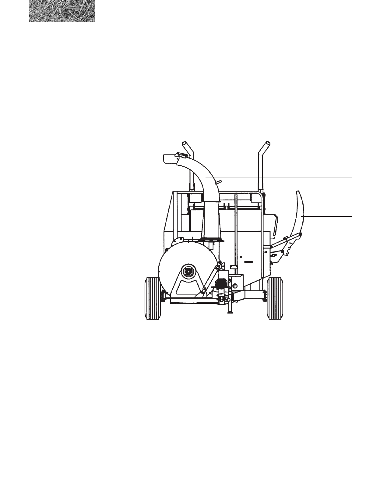
Figure 1.1
Rack, discharge spout
and fan housing in the
transport position
discharge spout
in transport position
rack folded in
transport position
This machine is designed to fold for ease of transportation and storage. The rack assembly folds inside of bale
chamber. A commercial diver’s license may be required to tow this unit on public roads; verify with trafc control or
licensing authorities.
• Use good judgment and drive slowly over rough or uneven terrain.
• Be sure tractor brakes are properly adjusted and foot pedals are locked together.
• When preparing implement for transport, it is recommended that the tines be removed or a pin be
removed on each tine so they can pivot into the bale chamber.
• The discharge spout must be rotated to an upright position, and the fan housing must be locked in position
with the strap bolted on the right side of the main frame (see Figure 1.1).
• Check your state laws regarding the use of lights, slow moving vehicle signs, safety chain and other
possible requirements.
2574 BALEBUSTER OPERATING INSTRUCTIONS
11
Page 22
Section 2: Dealer preparation
2.1 Assembly required
1. Hitch the BALEBUSTER to the tractor drawbar. Adjust the hitch so machine is parallel with ground.
2. Raise the jack. Pull the lock pin and store in the transport position.
3. Mount fork tines to loader frame..
4. Attach the PTO shaft to the tractor PTO shaft.
Depress coupling and slide the coupling onto the
splined shaft. Make sure the spring loaded safety
catch is properly seated.
5. Pull rack assembly into operating position.
6. If required, install the safety chain. Check local
regulations regarding safety chain requirements.
For more information
see section 3.3.1 “Tractor
Set Up”
7. Grease PTO before use.
safe distance from PTO
8. This machine is set up to operate on 1000 RPM
only!
2.2 Pre‑delivery inspection
INSTRUCTIONS: Before delivering the machine, check the following items carefully and make corrections when
necessary. Place an “X” in the box after each item has been checked and found to be acceptable.
q Missing items or damage in transit.
q Loose bolts or set screws.
q Hydraulics components for leaks or damage.
q Lug bolts for tightness.
q Tires for proper air pressure.
q Condition of tire rims.
12
q Proper lubrication.
q All chains for proper adjustment.
q All shields for installation and condition.
q Condition of all decals.
q All phases of operation.
q Check for loose ail bolts, torque to 150 ft. lbs (21.5 kg-m).
2574 BALEBUSTER OPERATING INSTRUCTIONS
Page 23
2.3 Machine operation check
With Tractor hooked up to the BALEBUSTER, try all functions on the machine.
WARNING: The electric\hydraulic system is polarity sensitive, reversing polarity will cause damage
to the solenoid P\N (4000174)
CAUTION: The electric\hydraulic system has a check valve installed on the valve. Oil will ow
only one direction from the tractor thru the valve.
With the engine off and key removed from the switch:
1. Adjust the spout, the fan housing should turn.
2. Adjust the deector tip on the spout.
3. Adjust the slug bar
With the engine at idle:
1. Raise and lower the loading arms.
2. Adjust the spout if equipped with the hydraulic motor option.
3. Engage the bale conveyor, adjust conveyor speed control valve on the BALEBUSTER.
4. Engage the tractor PTO, the rotor, transfer auger, and fan should be running. Listen for any odd noises
and vibrations.
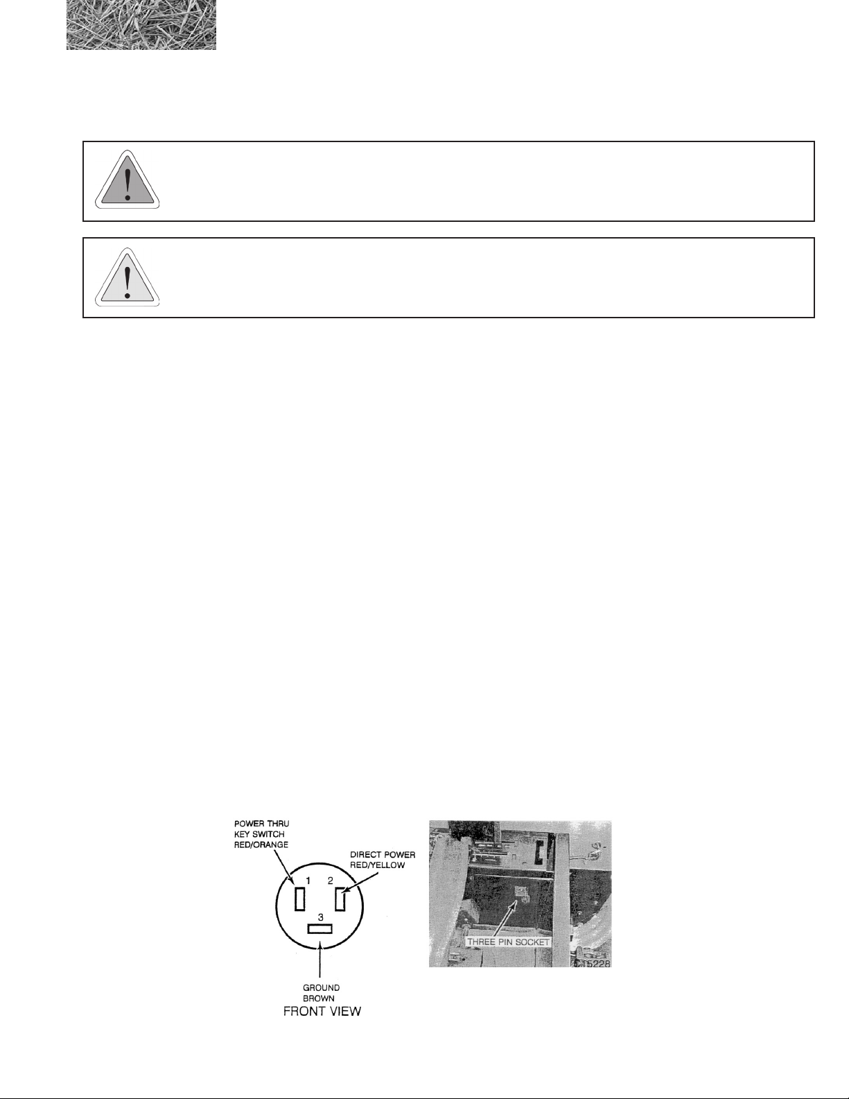
Three Pin Socket
An auxiliary power connection is provided inside the operators compartment for connecting monitors, implement
controllers, C.B. radios and other 12-volt equipment.
The three pin outlet is located on the right hand side to the rear of the seat. The outlet has a ground terminal and two
12-volt power terminals. One power terminal is through the key switch and the other is direct power.
2574 BALEBUSTER OPERATING INSTRUCTIONS
13
Page 24
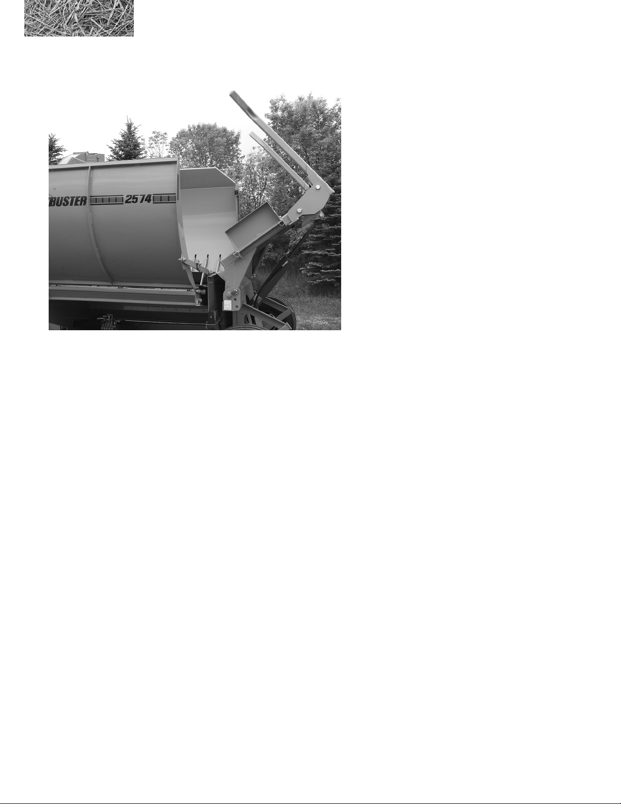
2.4 Loading tines
For shipping purposes the loading tines are placed on the loader as shown above.
After receiving the machine the loading tines need to be removed and put into the working position. See section 3.3.12
Loader for setting the position of tines for bales.
14
2574 BALEBUSTER OPERATING INSTRUCTIONS
Page 25
Section 3: Operation
To insure long life and economical operation, we highly recommend the operator of the BALEBUSTER be thoroughly
instructed in the maintenance and operation of the machine.
There is no substitute for a sound preventative maintenance program and a well trained operator.
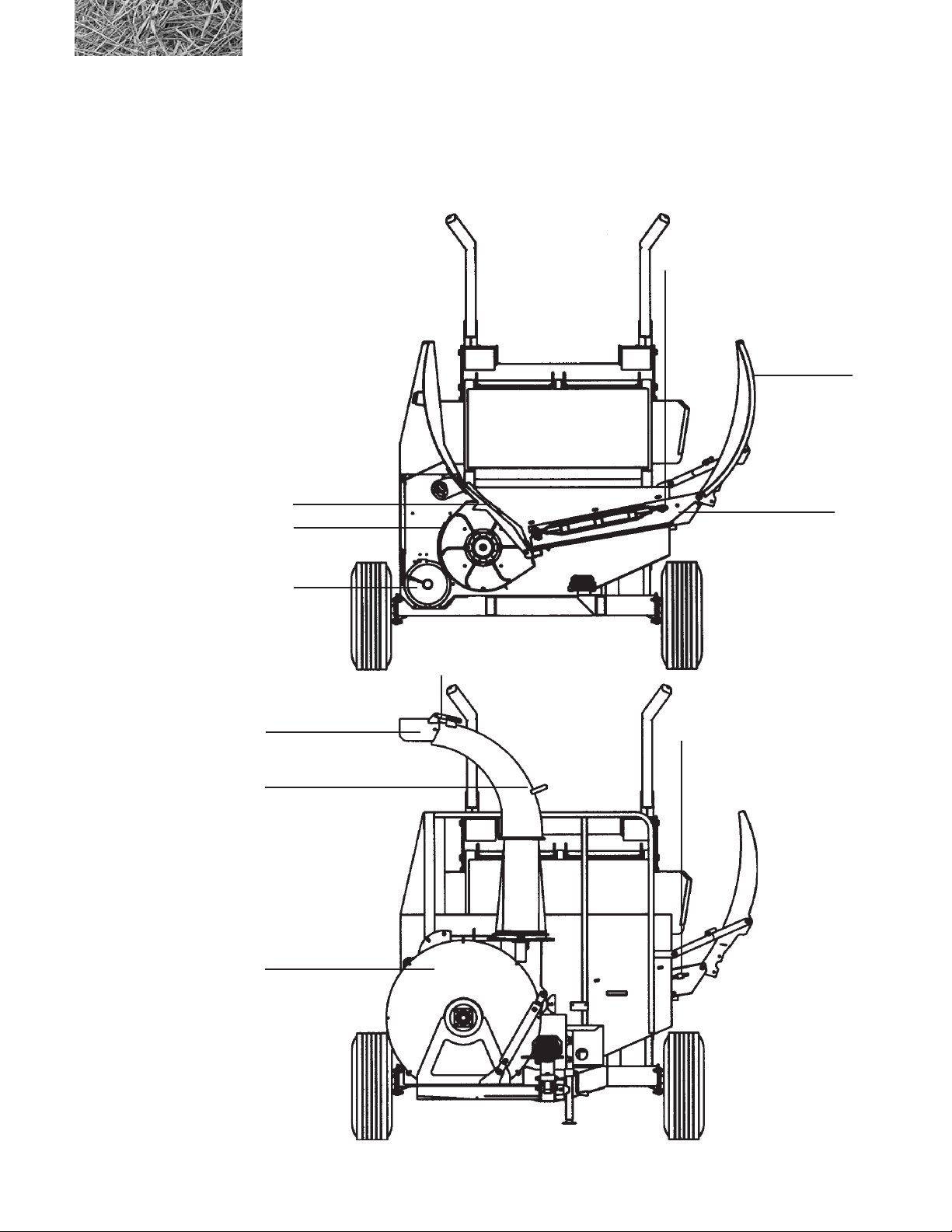
Figure 3.1
Location of major
components
slugbar
screen
auger
bale conveyor
tension adjustment
bolt
rack
bale conveyor
deector
adjustment
deector
discharge spout
fan housing
2574 BALEBUSTER OPERATING INSTRUCTIONS
bale conveyor
tension adjustment
bolt
15
Page 26
3.1 Pre‑operation inspection
Prior to starting the engine of the tractor, we recommend the operator make a visual inspection of the unit. This can be
done as the lubrication is being carried out. Any items that are worn, broken, missing or needing adjustment must be
serviced accordingly before operating the BALEBUSTER.
WARNING: Before inspecting the machine, use the normal shut-down procedure in section 3.3.4.
Check the following:
q Transfer auger and screen for material buildup, and chunks from screen that have fallen into the transfer
auger.
q Condition of ails and attachment bolts. Flail nuts are to be tightened to 150 ft. lbs (21.5 kg-m).
q Rotor for twine build-up.
q Chains for proper tension, and condition.
q Keep auger pan door closed during operation
q Check for loose bolts, worn or broken parts.
q All lubrication points have been serviced.
q Lug nuts for tightness.
q Condition of tire rims.
q Tires for proper air pressure.
q Installation of slow moving vehicle (SMV) sign if required.
q Installation and condition of shields.
q Condition of decals.
q Hydraulic components for leaks or damage.
WARNING: Hydraulic uid escaping under pressure can be almost invisible and can have sufcient
force to penetrate the skin. When searching for suspected leaks, use a piece of wood or cardboard
rather than your hands. If injured, seek medical attention immediately to prevent serious infection or
reaction.
16
q Test run the BALEBUSTER before loading. To prevent damaging the BALEBUSTER always engage
PTO with engine idling. Look for excessive vibration, loose or broken parts. Make any necessary repairs
before attempting to do any bale feeding.
2574 BALEBUSTER OPERATING INSTRUCTIONS
Page 27
3.2 Introduction to the machine
3.2.1 Operator controls
Operator controlled items:
• The loading tines, to load the bale. See section 3.3.6, “Loading”
• The PTO shaft, which runs the fan, auger, and rotor.
• The bale conveyor chain.
Adjustable items:
• The conveyor speed control valve. See section 3.4.4, “Adjusting the bale conveyor speed”
• Slug bar setting
• Screen size
• Spout and spout deector settings
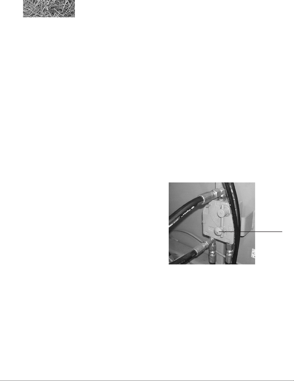
3.2.2 Bale conveyor
The Bale conveyor keeps the bale moving into the ails,
forcing the bale to rotate, and keeping product in front of
the ails
Bale conveyor speed is set with the conveyor speed control
valve or tractor controls if equipped with a PFC system.
To chop the forage ner, decrease the conveyor speed by
bale conveyor
speed control
valve
rotating the control lever up and to the left. For a coarser
cut, increase the conveyor speed by rotating the lever to the
right and down.
3.2.3 Rotor
The rotor ails shred the bale and throws the material into the augers. Rotor speed should remain constant, which is
done by keeping the tractor PTO at 1000 RPM.
2574 BALEBUSTER OPERATING INSTRUCTIONS
17
Page 28
3.2.4 Auger
Transfers material from rotor chamber to fan, driven by the rotor.
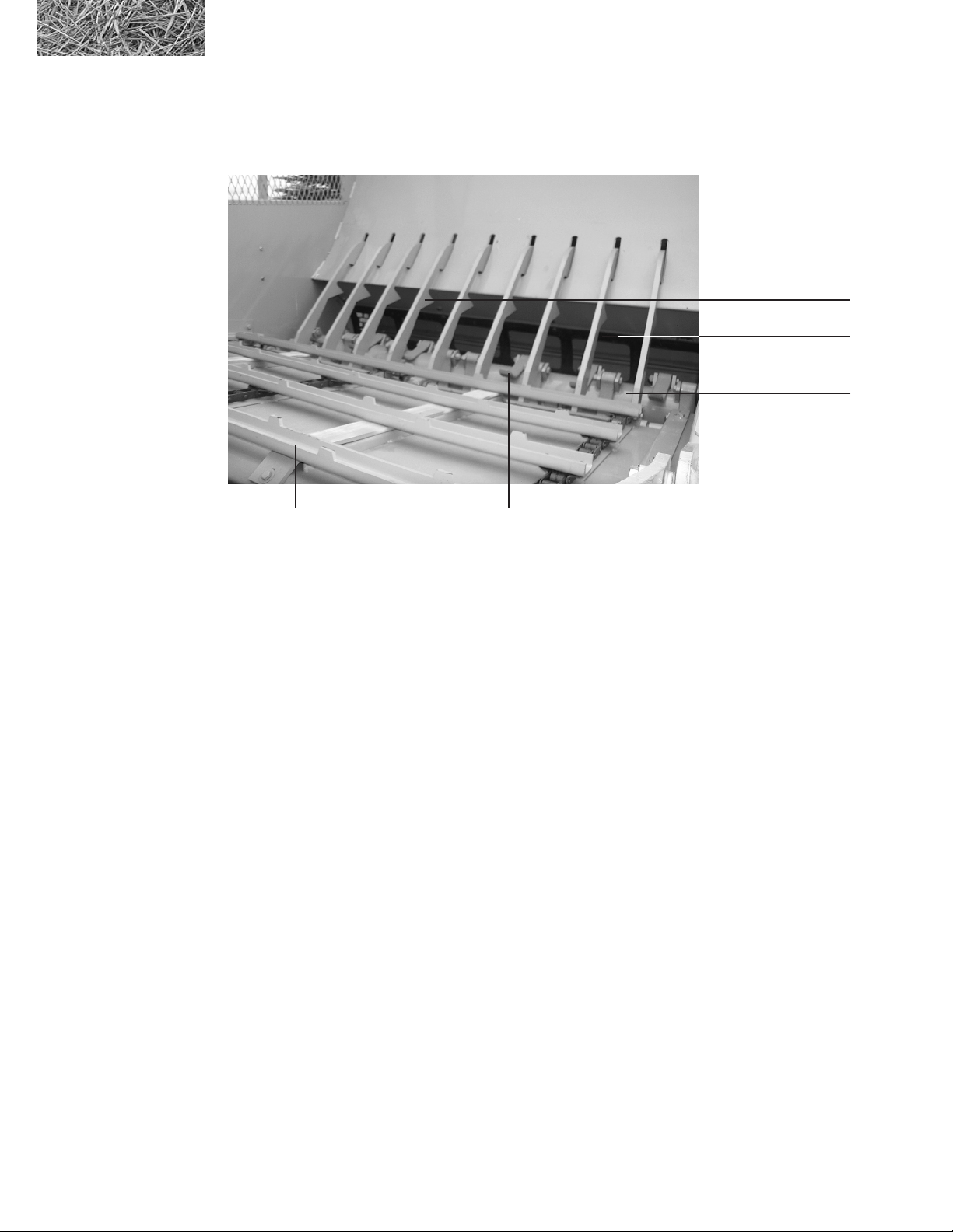
Figure 3.2
Rotor, bale conveyor,
slug bars, and the
screen
slug bar
screen
rotor
bale conveyor
rotor ails
3.2.5 Slug bars
The 2574 BALEBUSTER comes standard with 9 slug bars. The slug bars control the depth that the ails cut into a
bale as it is being shredded. As the depth of the cut becomes larger, the output becomes coarser. The depth of cut is
controlled by the slug bar ratchet. For more information, see section 3.4.5 on changing the slug bar settings.
3.2.6 Screen
Screens are used in the 2574 to regulate product size. Screen sizes are 4-1/4”x10-1/2”, and 6-1/2”x10-1/2”
openings. The larger the hole, the coarser the product. Screens can be reversed when one edge becomes worn. See
section 3.4.3 on changing screens.
3.2.7 Fan
Material goes through fan and is blown out discharge. Driven by PTO.
3.2.8 Dischargespoutanddeector
The discharge spout and deector assembly can be adjusted for different scattering effects. Raise the deector
for a wider spread. Lower the deector for a narrower windrow. Rotate the discharge spout and fan housing for
distribution near the machine or farther out.
18
2574 BALEBUSTER OPERATING INSTRUCTIONS
Page 29
3.3 Machine Operation & Adjustments
3.3.1 Tractor Set Up
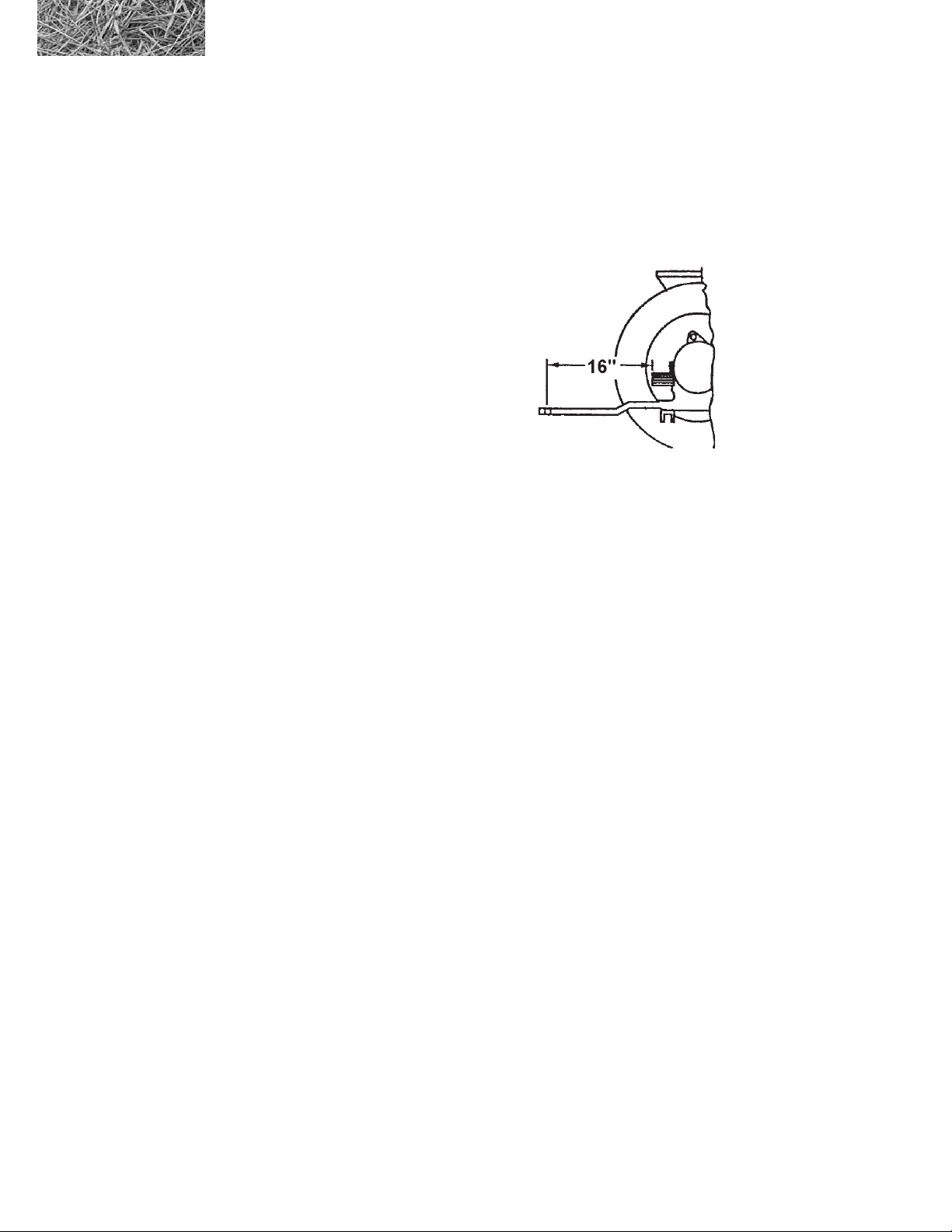
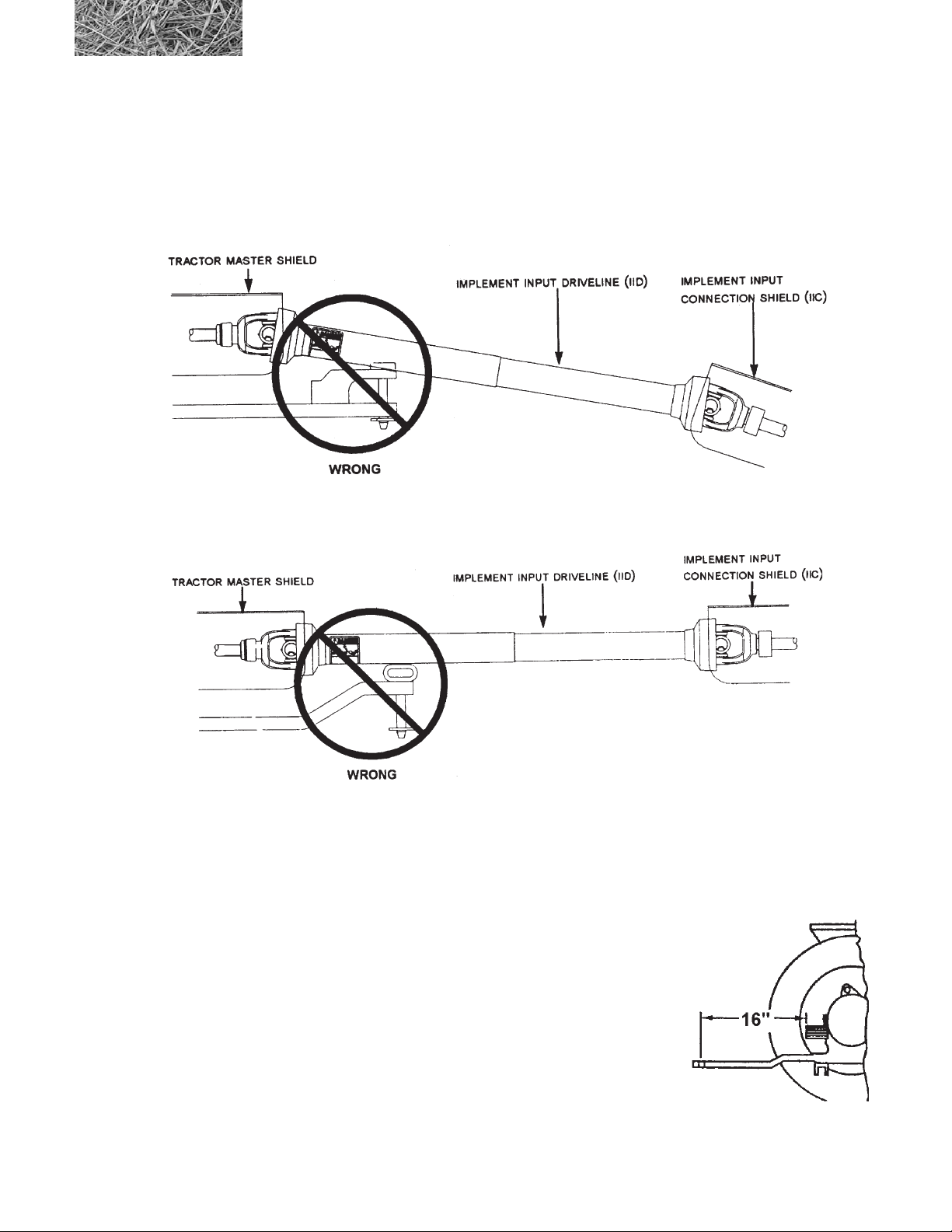
A tractor drawbar and 3-point arms can cause interference with the PTO driveline IID (Implement Input Driveline).
This interference can cause serious damage to the IID guarding and the IID telescoping members.
If this implement is attached to a tractor with a clevis hitch (hammer strap) style drawbar, the hammer-strap must be
removed to prevent damage to the IID guarding and the IID telescoping members. See Figure 1.
Figure 1
If this implement is attached to a tractor with an offset in the drawbar, be certain it is in the down position to prevent
damage to the IID guarding and the IID telescoping members. See Figure 2.
Figure 2
If this implement is attached to a tractor with 3-point arms, the arms must be fully raised and locked in position to
prevent damage to the IID guarding and the IID telescoping members.
Hitch Adjustment
The hitch is adjustable so that the machine is parallel to the ground when attached
to the tractor drawbar. This is accomplished by removing the two mounting bolts
and reinstalling them with the hitch at the proper height. The distance from the end
of the P.T.O. shaft on the tractor to the center of the drawbar hitch pin hole should
be 16” (41 cm.), and the height from the top of the drawbar to the centerline of the
P.T.O, should be 8”. Refer to Page 20.
The hitch pin should be of proper size to prevent movement and length to extend
through all components of the hitch. The pin should be secured with a hairpin clip
or suitable device to prevent the loss of the pin.
2574 BALEBUSTER OPERATING INSTRUCTIONS
19
Page 30
3.3.2 Hitching the BALEBUSTER to a tractor
To hitch the BALEBUSTER to a tractor, perform the following steps:
1. Adjust jack for tractor height
2. Position tractor so hitch pin can be installed, and
install the hitch pin.
3. Adjust jack so that the jackstand is loose. Then
place jackstand in the raised and locked position.
4. Attach PTO to tractor.
5. Clean off the hydraulic hose ends and tractor
couplings, then attach the hydraulic hoses.
6. Verify hydraulic hoses are hooked up in proper
orientation.
7. Raise loading table before moving.
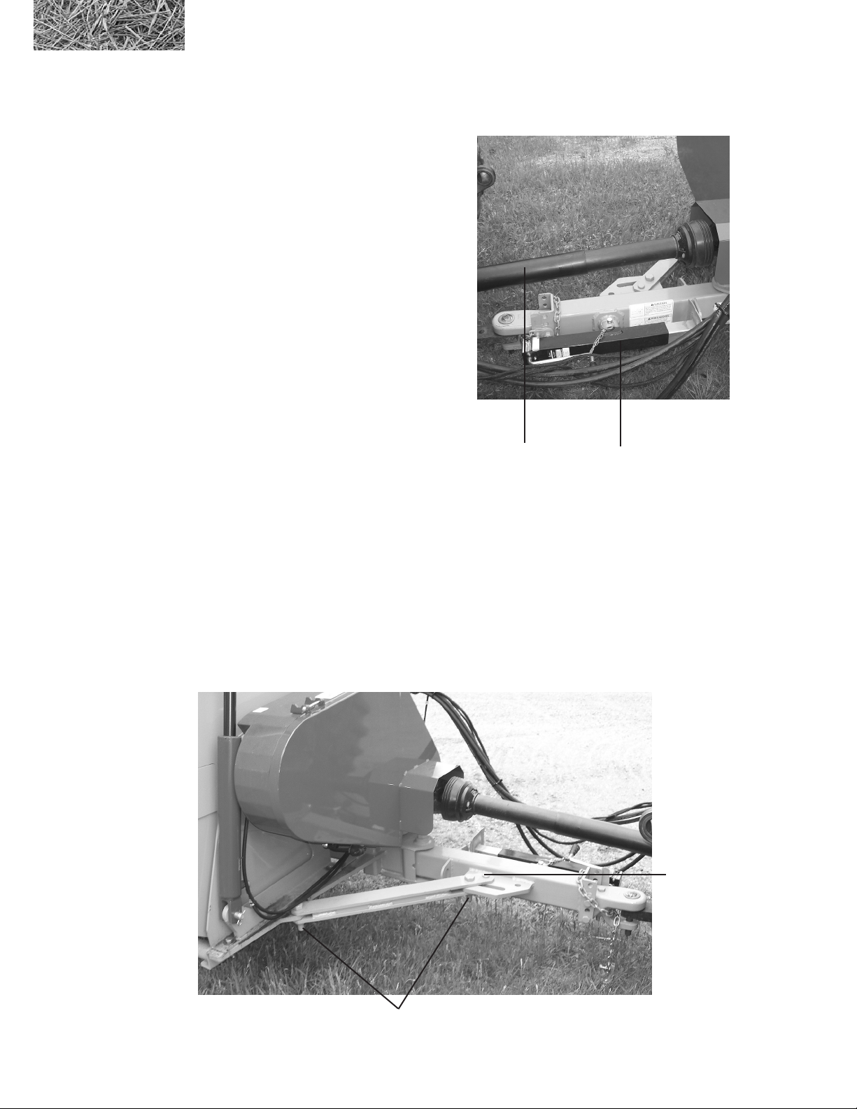
3.3.2A Movable Hitch
PTO
front jack stand (hitched
position)
The 2574 BALEBUSTER is equipped with a two position moveable hitch, a transporting position and a working
position.
When the hitch is in the transporting position, the 2574 BALEBUSTER will center the machine behind the tractor. In
the working position the 2574 BALEBUSTER will follow off to the right of the tractor.
To change the positions of the hitch, loosen the 1” diameter bolts, top lock nuts and remove the clevis and hair pin.
For the working position, move the hitch so that it is straight out from the machine and the brace lines up with the hole
closest to the machine. Replace the clevis pin and hair pin in the hole and tighten the 1” diameter bolts and top lock
nuts. For the transport position, move the hitch so that the brace lines up with hole closest to the front of the hitch.
Replace the clevis pin and hair pin in the hole and tighten the 1” diameter bolts and top lock nuts.
Hitch shown in
working position
Clevis pin & hair pin
20
1” Bolt and nut
2574 BALEBUSTER OPERATING INSTRUCTIONS
Page 31

3.3.3 Starting the machine
WARNING: After making all necessary hook-ups to tractor, be sure rotor chamber is clear of any
solid objects. Make sure any bystanders are away from discharge before engaging PTO. Flying
objects can cause serious injury or even death. Stay clear of discharge side of machine unless
operator has stopped tractor engine and machine has stopped rotating. Failure to follow these
instructions may result in severe injury.
To start the machine, perform the following steps:
1. Machines hydraulic system performs two (2) functions. One function raises the bale loader for loading
bales into the machine. The second function powers bale conveyor by means of a hydraulic motor.
2. Operating tractor PTO at 1000 RPM allows machine to do a better job of chopping forage and also keeps
a minimum of twine build-up on the rotor. Twine build-up should be kept to a minimum to reduce re
hazard.
3. Always operate bale conveyor to rotate the bale in direction indicated by arrow on the front shield.
Reverse direction only if the bale is lodged or hesitates to turn
4. CAUTION: Serious injury could result if machine is allowed to tip.
2574 BALEBUSTER OPERATING INSTRUCTIONS
21
Page 32

3.3.4 Normal shut‑down procedure
WARNING: For your safety and the safety of others, you must use the following normal shut-down
procedure before leaving the tractor controls unattended for any reason, including servicing, cleaning,
or inspecting the BALEBUSTER. A variation of the following procedure may be used if so instructed
within this manual or your tractor manual or if an extreme emergency requires it.
To shutdown the machine, perform the following steps:
1. Shut hydraulic drive off for chain conveyor, and wait until the fan and auger are emptied out.
2. Reduce engine RPM to a low idle, wait for the fan to slow down. Disengage PTO.
3. Lower machine to ground level.
4. Place transmission in park or set park brake
5. Shut Off engine and remove key.
6. Wait for all movement to stop.
3.3.5 Unhitching the BALEBUSTER from a tractor
To unhitch the BALEBUSTER from a tractor, perform the following steps:
1. Follow Normal shut-down procedure
2. Lower jack and secure. Raise tongue off of the tractor draw bar
3. Detach the PTO shaft from the tractor.
4. Cycle the hydraulic control levers to release any pressure in the hydraulic hoses. Be sure loading table is
completely down.
5. Detach the hydraulic hoses.
6. Detach electrical cable.
7. Remove the safety chain, if installed
8. Remove the hitch pin.
9. Place jackstand in the down and locked position. Lower BALEBUSTER into jackstand. Raise Jacks.
22
2574 BALEBUSTER OPERATING INSTRUCTIONS
Page 33
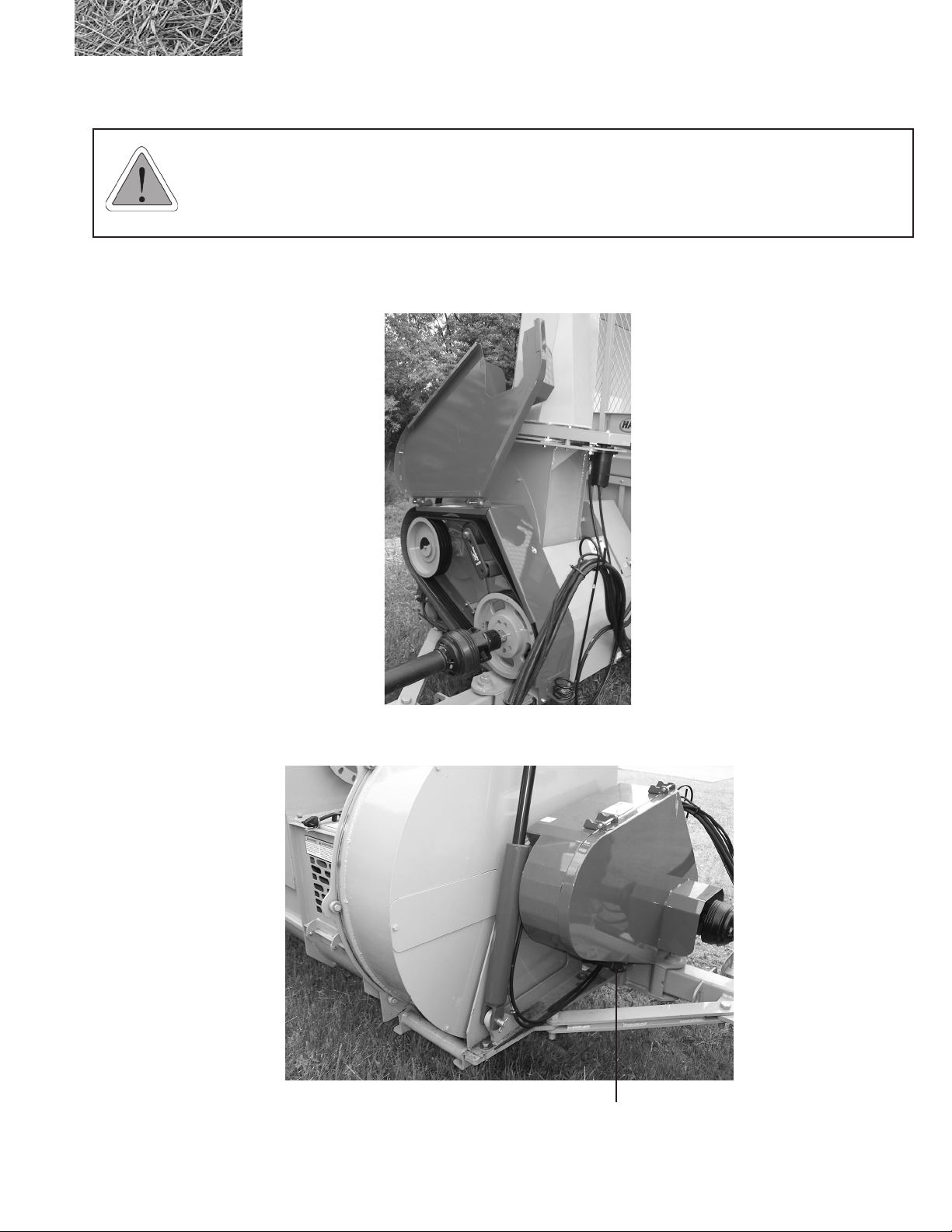
3.3.6 P.T.O. Shield and Belt Access Cover
WARNING: Before opening the P.T.O. and the belt access shield, be sure and follow the normal
shut down procedure. Be certain that the tractor is shut off and all rotating components of the machine
have come to a complete stop before opening the shield. Loose clothing is discouraged, and long hair
should be restrained whenever working on the P.T.O. shafts.
To open the P.T.O. shield and belt access cover, unhook the rubber latch on the bottom of the shield and open shield as
shown below.
gure 3.3a
P.T.O. shield & belt
access in maintence
position
When done working on the P.T.O. or belts, close shield and re-hook the rubber latch. As shown below.
gure 3.3b
P.T.O. shield and belt
access in working
(latched) position
2574 BALEBUSTER OPERATING INSTRUCTIONS
Rubber latch
23
Page 34
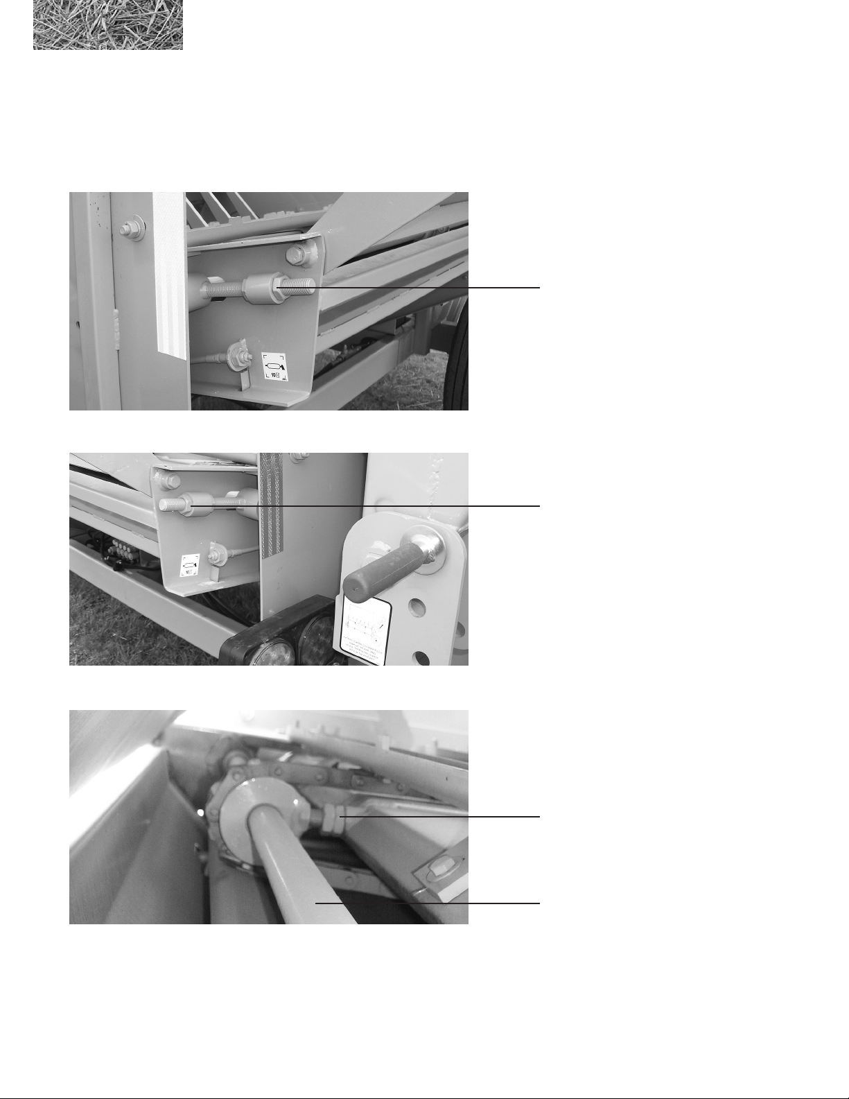
3.3.7 Conveyor Chain Adjustment
The three chain tensioning bolts should be adjusted to allow lifting of the slats 1” to 1-1/2” above the conveyor deck.
These bolts are located on the front of the conveyor at the center and on the rear. Bolts must be adjusted evenly.
Conveyor shafts must be straight. Over tightening the center chain tensions will damage bearing and slats.
Left conveyor chain
adjustment bolt
Right conveyor chain
adjustment bolt
Center conveyor chain
adjustment bolts
Conveyor shaft
24
2574 BALEBUSTER OPERATING INSTRUCTIONS
Page 35
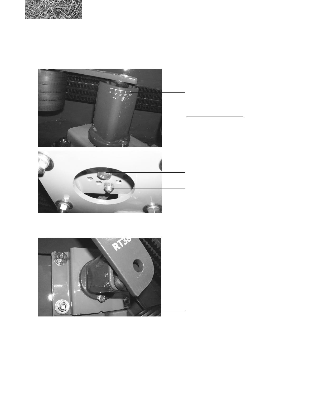
3.3.8 Adjusting Belt Tension
Using the pretension angle marking located in the corner of the outer housing as a reference; loosen the center
mounting bolt. With the large wrench provided, hold the outer housing and remove the index bolt. Continue turning the
outer housing until the proper amount of tension has been applied, 20 to 30 degrees.
DO NOT EXCEED 30 DEGREES OF PRE-TENSION!
Pretension angle
markings
WRENCH
8102154 - Auger Drive
8102155 - Fan
Mounting bolt
Index bolt
The tensioner mounting plates have a notch on one side, turning the mount 180 degrees will move the adjustment index
holes a half step.
Tensioner mounting plate notch
For a setting that is halfway between the holes on the mounting plate, rotate the mounting plate 180 degrees and
re-tension the bolts.
When belts are at the proper tension, install index bolt and tighten. Tighten the center mounting bolt and re-check
pre-tension angle on the outer housing.
2574 BALEBUSTER OPERATING INSTRUCTIONS
25
Page 36
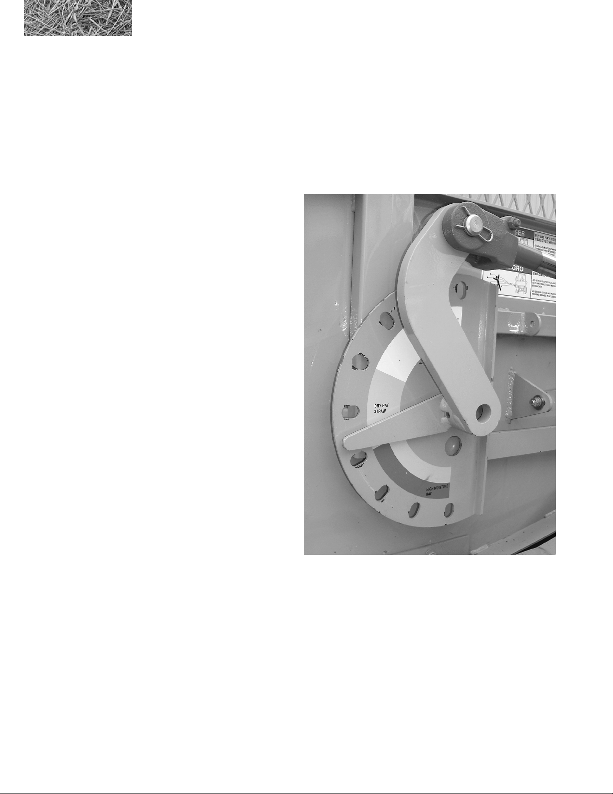
3.3.9 Slugbar Adjustment
Exposing, less ail will create a ner cut and use less horsepower, while exposing more ail will produce a coarser cut.
This is accomplished by rotating the slugbar adjustment handle. Rotating the handle counterclockwise will expose more
ail, clockwise will expose less ail. To rotate the handle, squeeze the lever to release the lock and rotate the handle to
the desired position, and release the lever. Be sure that the lever is seated in one of the adjustment slots to ensure that
slugbars stay properly adjusted.
With the handle rotated fully clockwise the will expose the least amount of ail (position 1).
Position Approx. Flail Exposed
1 1“
2 1-1/8”
3 1-1/4”
4 1- 3/8”
5 1-1/2”
6 1-9/16”
7 1-5/8”
8 1- 11/16”
9 1-3/4”
Positions 1 through 4 are for grinding
hay. Positions 4 through 6 should only
be used when spreading Dry Straw.
(DO NOT, use positions 6 through 9
if material is wet, has high moisture
content or is frozen.)
2
3
4
5
6
7
8
Shown with hydraulic slugbar adjustment
1
9
26
2574 BALEBUSTER OPERATING INSTRUCTIONS
Page 37
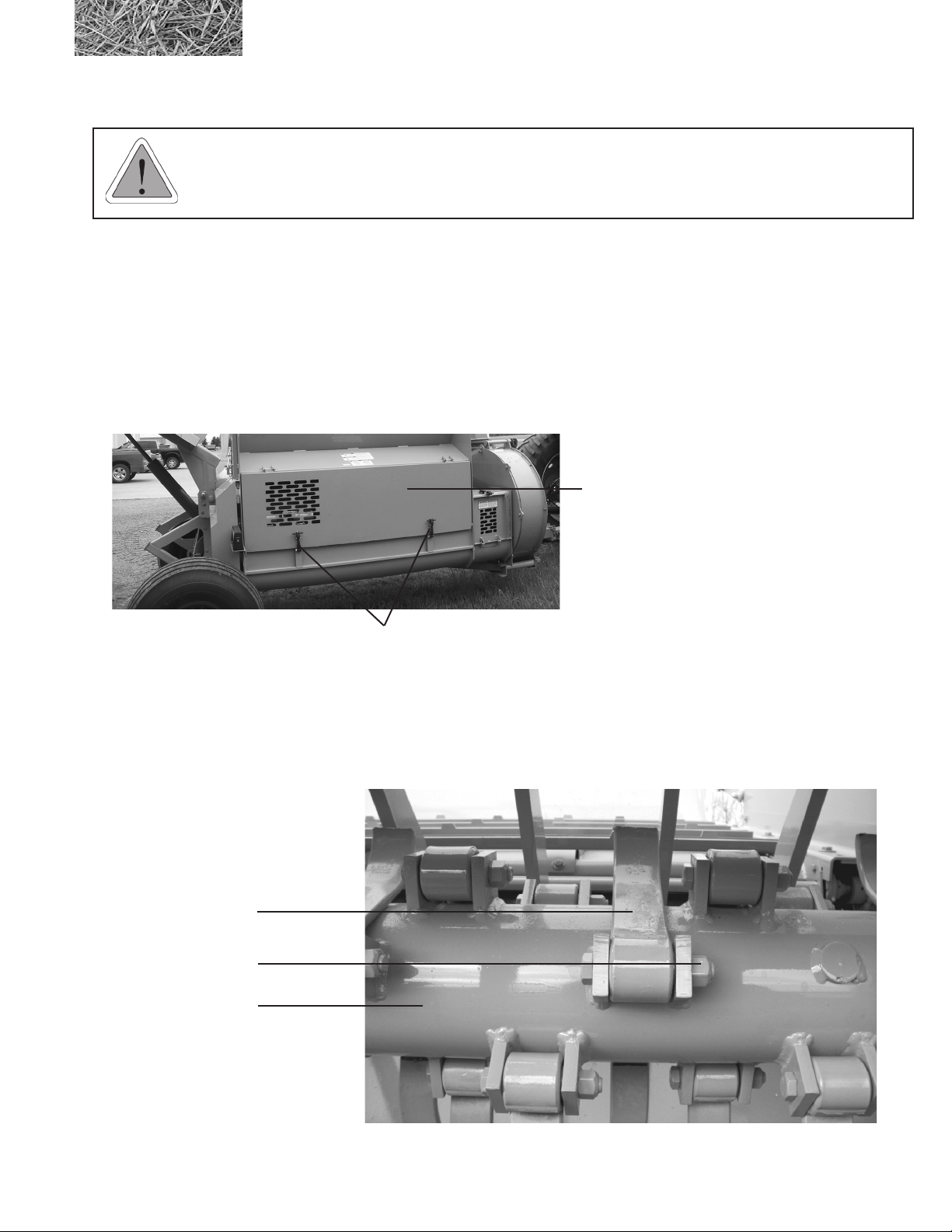
3.3.10 Clean Out Door
WARNING: Before opening the clean out door, be sure and follow the normal shut down procedure.
Be certain that the tractor is shut off and all rotating components of the machine have come to a
complete stop before opening clean out door.
The clean out door allows for easy access to the rotor for
ail changes and twine removal. To open the door release
the rubber latches. Lift open the door.
To close the door, hook the rubber latches. This should
draw the door in tight. If the door is loose or can not be
closed, check for obstructions. Hooks can be adjusted by
screwing them in or out of the latch.
clean out door in the
closed position
clean out door
rubber latchs
3.3.11 Flails
Flails must to be free to rotate about the bushings on the rotor. The bushings must not rotate. The bushings are held
secure by tightening the bolts which squeeze the tabs against the bushing. Bolts should be torqued to 156 ft.-lbs.
(21.5 kg-m).
gure 3.4
rotor and ails
ail
ail tightening bolt
rotor
2574 BALEBUSTER OPERATING INSTRUCTIONS
27
Page 38
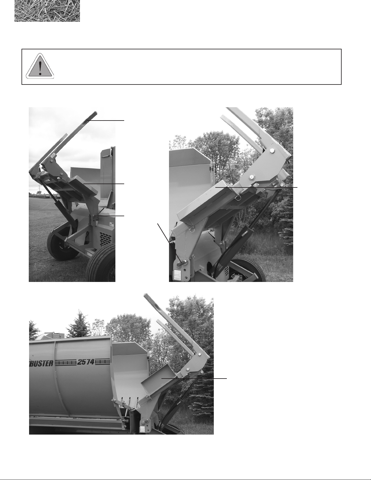
3.3.12 Loader
WARNING: Loader tines may swing down unexpectedly as they drop over center. They can move
faster than you can react. Keep all bystanders away from the machine while loader is raised.
gure 3.5
Loader Tines right side
loader tine
loader wing
loader
transport pin
gure 3.5A
Loader Tines left side
Folding loader
wing in working
position
28
Folding loader wing in
transport position
2574 BALEBUSTER OPERATING INSTRUCTIONS
Page 39
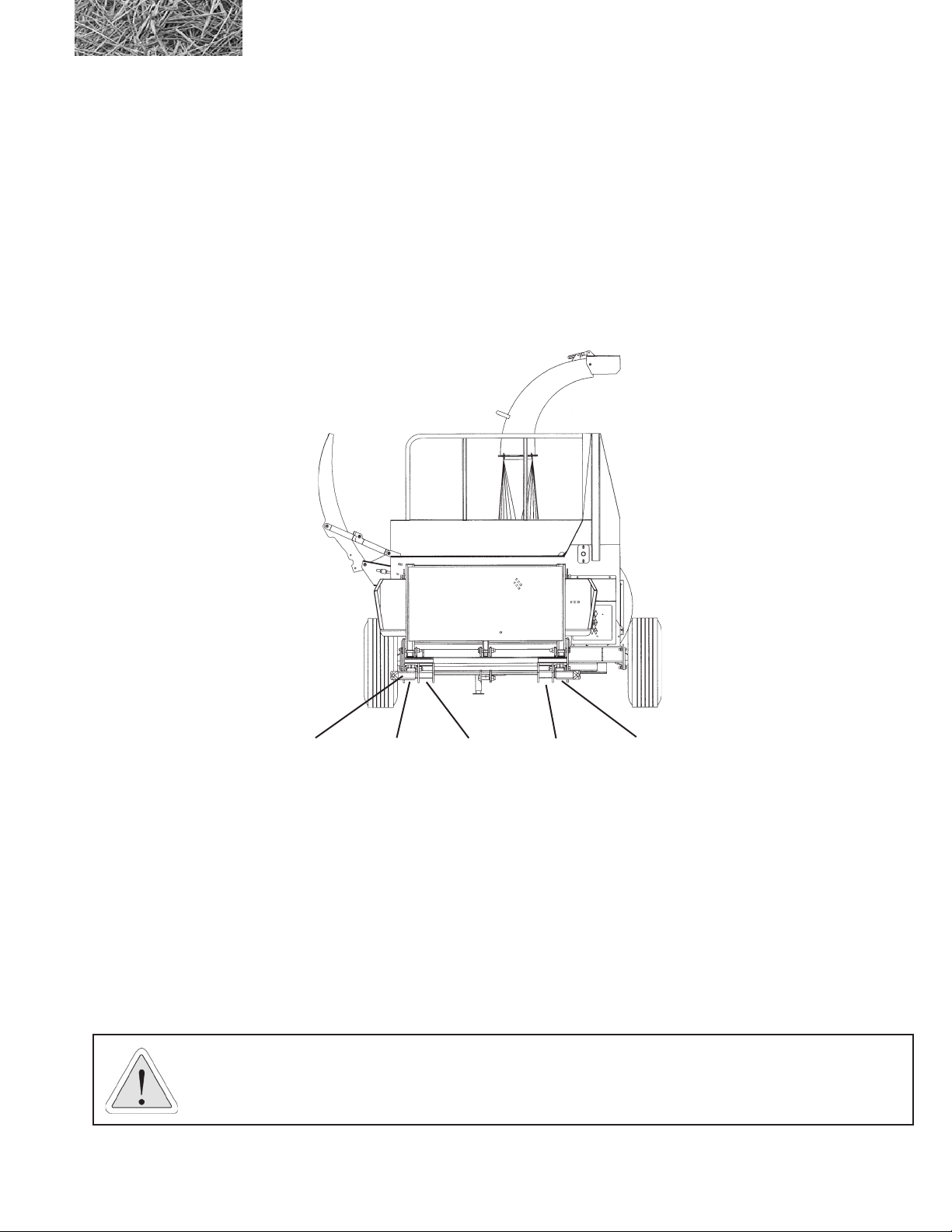
1. The loader has three settings for different size bales. For bales approximately 72” in diameter mount the
loader tines in the outermost position. 60” bales require the loader tines to be positioned in the left outer
slot and the right inner slot (left and right are determined while facing in the direction of travel). 48”
bales require the tines to be positioned in the inner mounting slots (see below)
2. 48” bales use left inner and right inner mounting slots.
60” bales use left outer and right inner mounting slots (standard).
72” bales use left outer and right outer mounting slots.
loader tine left innerleft outer right outerright inner
Tine mounting brackets
3. These settings are accomplished by removing the pivot bolts and removing the tine. After the tine is
reinstalled in the proper position, reinstall the pivot bolt and tighten. Be sure the bolt threads protrude
though the entire nut so that the locking nut functions properly. Do not over tighten the pivot bolt, the tine
should rotate freely about the pivot bolt.
4. The loader tines should pivot freely as the loader is raised and lowered. If the loader tines don’t swing
down into the loading position the bale will not load properly. With the loader fully raised the loader tines
should swing down.
CAUTION: Watch for overhead hazards such as power lines.
2574 BALEBUSTER OPERATING INSTRUCTIONS
29
Page 40
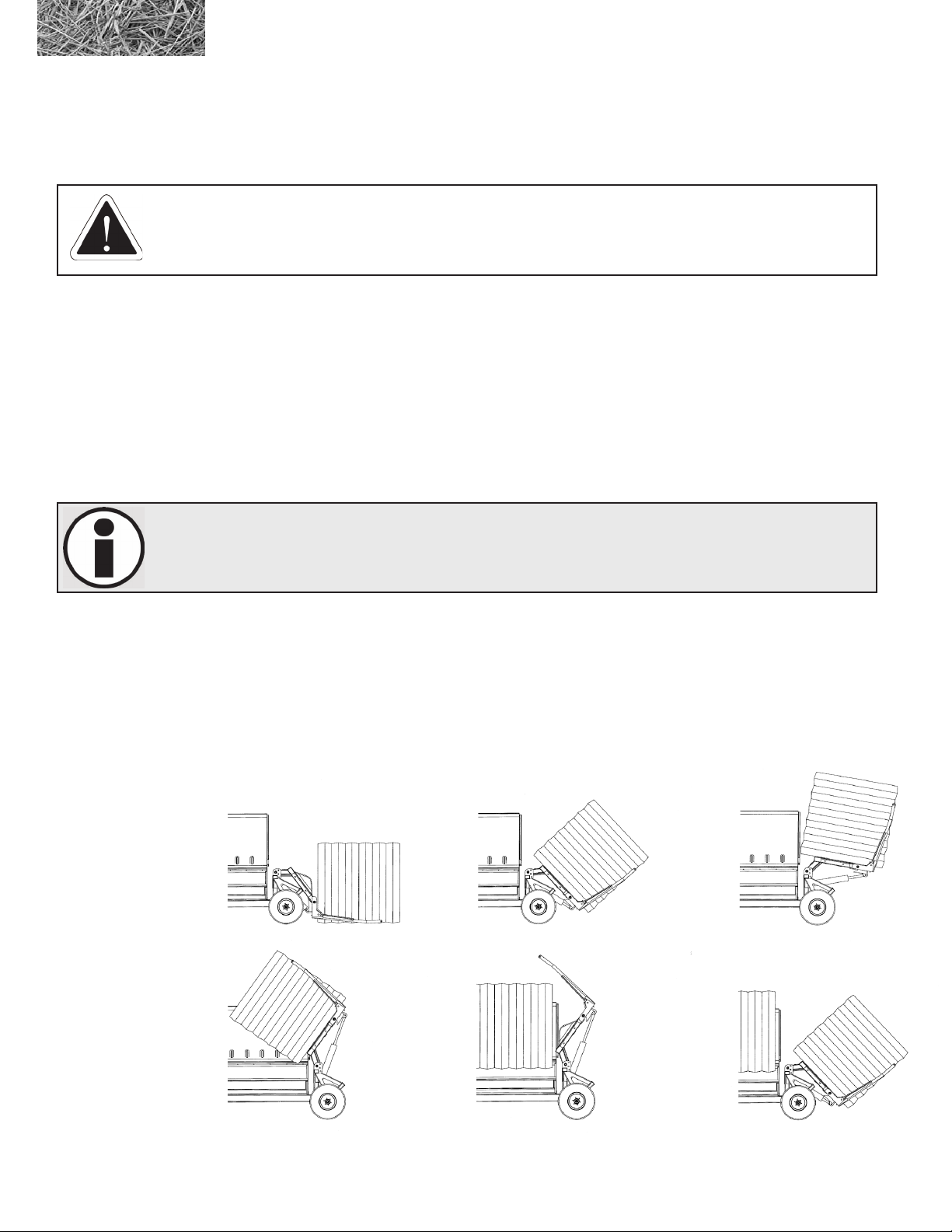
3.3.13 Loading the bale
The bale conveyor must not be running when a bale is lifted into the shredding chamber. (step3-5), dropping bales on
to the moving conveyor slats may bend slats.
DANGER: If it is necessary to transport a second bale over uneven terrain, make sure any
bystanders are away from the 2574 BALEBUSTER. Serious injury or death could result if the bale
rolls off the loader main frame loader supports.
STEP 1:Lower the bale loader part way down so you can so you can still see the end of the tine fork. Use
the fork as a guide and back up to the rst bale, with the bale loader in its lowest position, back up until
the bale is loaded on the main frame loader supports
STEP 2: Slowly lift bale, until the at end is frimly against the table. If you need to travel to the second
bale, transport with the bale loader on the main frame supports, use the bale as a guide to line up the
second bale.
STEP 3-5: Slowly lift bale into the shredding chamber. Continue lifting the bale loader until it stops. The
correct position for shedding a single bale will help prevent spillage.
NOTE: If bale does not rotate forward the twine may be over the tine. Cut the twine at this time to
prevent damage to the machine.
STEP 6: Load a second bale (if the rst bale is on the main frame loader supports, use the bale as a guide
to line up on the second bale). (If the rst bale is in the shredding chamber use the conveyor and move
the bale to the right so you can look past it on the left side). Back trailer until bale is loaded on the main
frame loader supports. Slowly lift the bale off the ground keeping the weight of the bale on the main
frame loader supports. This is the transport position for the second bale.
gure 3.6
loading the bale
30
STEP 7: After the rst bale is shredded, repeat steps, 3-5, loading and shredding the bale.
STEP 1 STEP 2 STEP 3
STEP 4 STEP 5 STEP 6
2574 BALEBUSTER OPERATING INSTRUCTIONS
Page 41
3.3.14 Operating the machine
To operate the machine, perform the following steps:
1. Load machine according to section 3.3.6 “Loading Bales”.
2. With tractor at half speed, engage PTO.
3. Increase tractor engine speed so PTO is at 1000 RPM.
4. Engage conveyor chain orbit motor hydraulics.
5. Drive as needed to spread as desired.
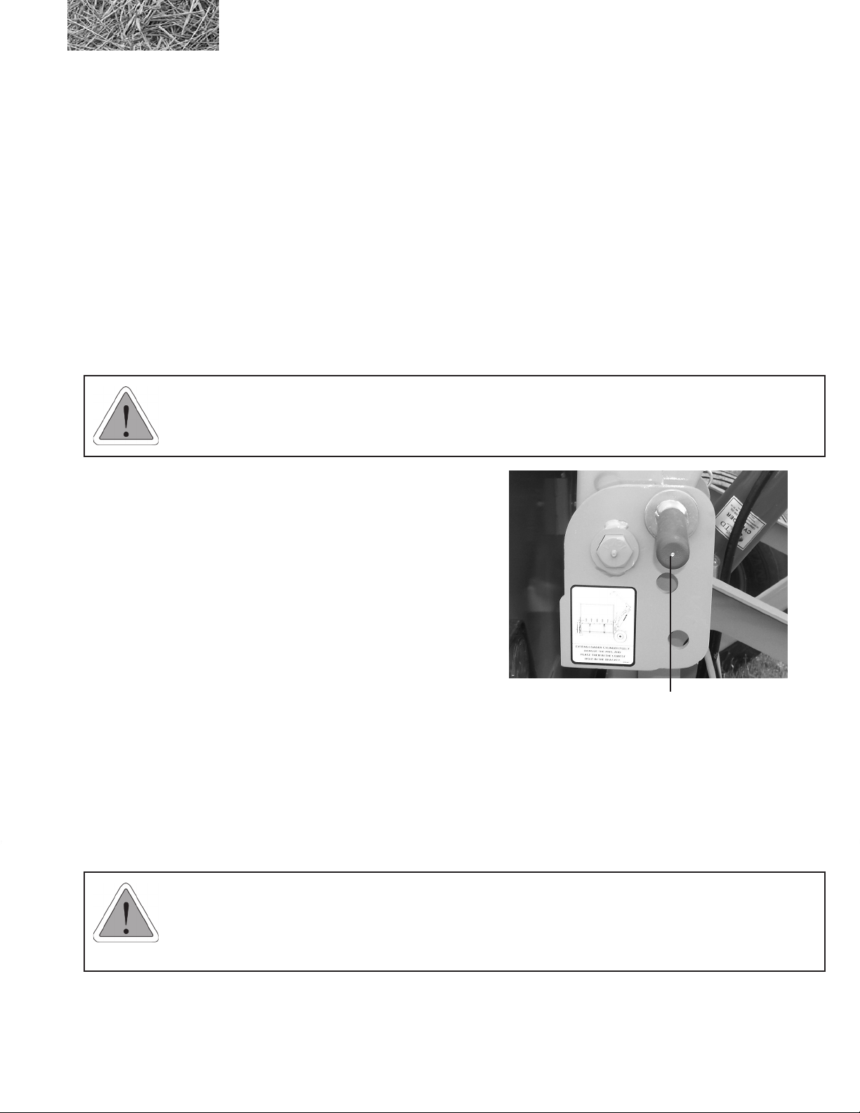
3.3.15 Loader Transport Pin
WARNING: Never stand under loader when removing transport pins. Do not attempt to force pins
out, with the loader fully raised they can be easily removed.
The loader transport pins can be inserted into three positions:
1. Upper hole: Holds the loader in the fully raised
position for transport.
2. Middle hole: Holds the loader partly raised. This
improves rear visibility and reduces wind drag
during transportation
3. Lowest hole: Holds the loader transport pin in
storage position.
loader transport pin in
transport position
3.3.16 Hydraulic Cylinder and Valve
All cylinder and valve hose connections should be tight and leak free. If the area near a hose connection becomes
oily or dirty repairs should be made to seal the leak. Hoses should be free of cracks or cuts to ensure safe operation.
Cylinder seal kits are available from your dealer to repair a leaky cylinder. Pin connections should be free of excessive
wear. If pins become worn they should be replaced. Also check yokes and mounts for cracks and wear.
WARNING: Hydraulic uid escaping under pressure can be almost invisible and can have sufcient
force to penetrate the skin. When searching for suspected leaks, use a piece of wood or cardboard
rather than your hands. If injured seek qualied medical attention immediately to prevent serious
infection or reaction.
2574 BALEBUSTER OPERATING INSTRUCTIONS
31
Page 42
3.3.17 Tires and Rims
Tires should be inated to 40 PSI (275 kPa) and should be free of cuts or cracks. There should also be adequate tread
and no visible cords, wires or tread separation. Tires must also be of proper load rating, speed rating and size.
Rims must be free of cracks and rust pitting. Lug bolts must also be tight. Inspect the area around the lug bolts. If rust
develops this is a sign of loose lug bolts. Check wheel bearings and seals, replace and grease as use requires.
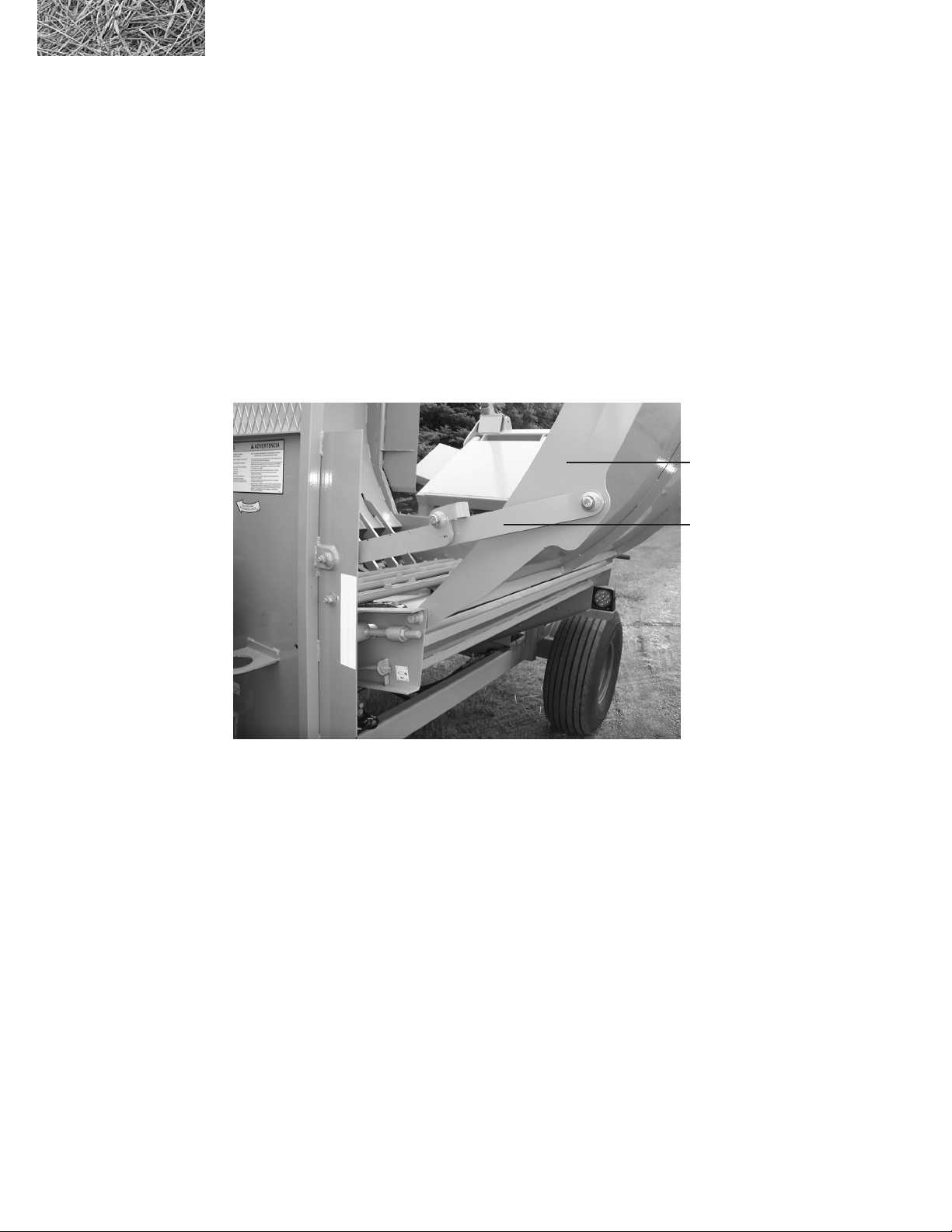
3.3.18 Rack
The rack has two positions: transport and working. The rack should travel between the two positions freely under the
operator’s own power. All pivoting connections should be snug, but still allow the points to hinge freely. Inspect for
cracked or excessively worn holes at the connections. The rack connection straps are designed to be self-folding and
should not drop over center. If the straps become bent or do not function properly they should be replaced.
gure 3.7
rack in the working
position, rack
connection straps
rack
rack connection strap
32
2574 BALEBUSTER OPERATING INSTRUCTIONS
Page 43
3.3.18A Rack Tool
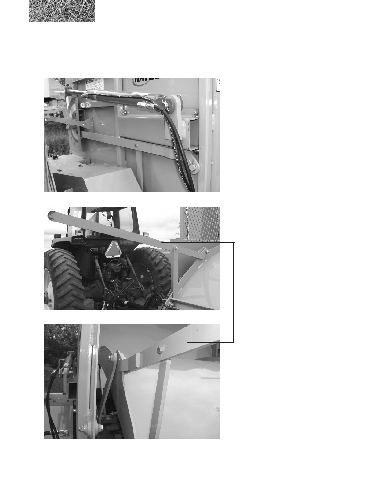
The 2574 BALEBUSTER comes with a rack tool for unfolding the rack from the transport position. The rack tool is
stored on the front of the shredder when not in use.
Rack tool in stored location
Rack tool in position for unfolding rack from
transport position
2574 BALEBUSTER OPERATING INSTRUCTIONS
33
Page 44

3.3.19 Jack
An adjustable jack is provided with the machine to support the hitch when the machine is disconnected from the tractor.
The jack must only be used on rm, level ground or similar base to prevent it from sinking,
When unhooking the machine remove the jack pin and rotate the jack to the upright position and reinstall the pin. Crank
the jack until the hitch is no longer supported by the drawbar of the tractor. The hitch pin can now be removed.
WARNING: Never use the jack without reinstalling the jack pin.
When hooking up the machine, install a proper hitch pin and secure it with a hairpin clip or comparable device, crank
the jack until the foot of the jack is fully raised. Remove the jack, and place in transport position.
3.3.20 Hooking up hydraulic control box and hydraulics to tractor
To hook up the hydraulic control box to the 2574 Balebuster, line up plug from the control box to the plug on the
machine and twist together. To disconnect twist opposite direction and pull apart.
Valves on the 2574 Balebuster are protected with a one way check valve to ensure proper function.
To engage tractor hydraulics so switches function correctly, turn on and lock one hydraulic function when operating the
shredder.
If the direction of the lever is not right for the tractor or does not lock, reverse the hydraulic hose hook ups on the
tractor.
Recommended hydraulic ow rate is 8 to 12 gallons a minute. If hydraulic ow is to low, it will cause the hoses to
pulsate and if the ow is too high, damage to the valve will occur.
To hook up to 12 volt power, one of two power plugs is needed. For newer tractors with a three prong plug a 15 amp
fuse is needed. For older tractors a wiring harness can be purchased (part #5700686) using a 15 amp fuse, and plugging
the harness into a keyed power source.
34
2574 BALEBUSTER OPERATING INSTRUCTIONS
Page 45
3.3.21 Fan
WARNING: The fan on the 2574 BALEBUSTER has an overrunning clutch. When the PTO is
disengaged, the fan will continue to rotate. Follow normal shut down procedure and WAIT for all
moving parts to STOP!
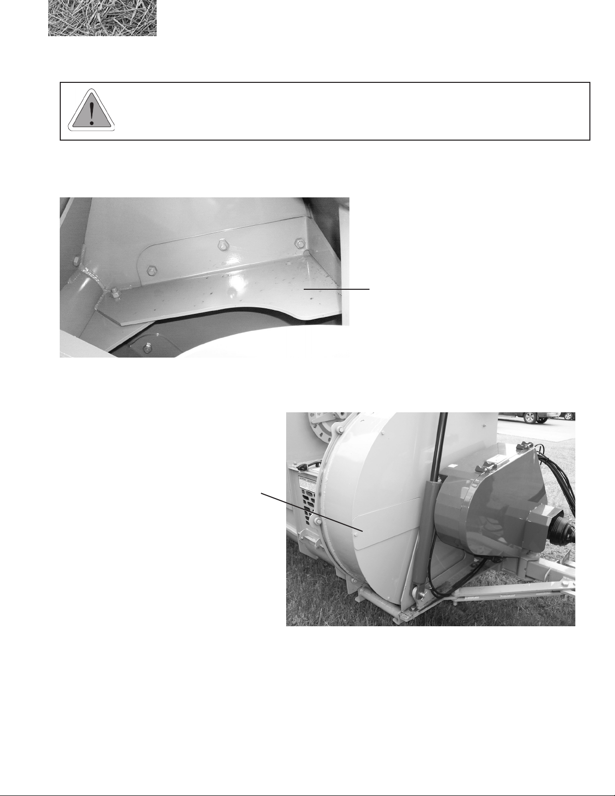
The fan assembly on a 2574 BALEBUSTER features bolt-in replaceable fan blades and shaft.
Bolt-in replaceable fan blade
An access cover is located on the front of the fan for replacing fan blades.
Access cover
2574 BALEBUSTER OPERATING INSTRUCTIONS
35
Page 46
3.4 Adjusting the machine
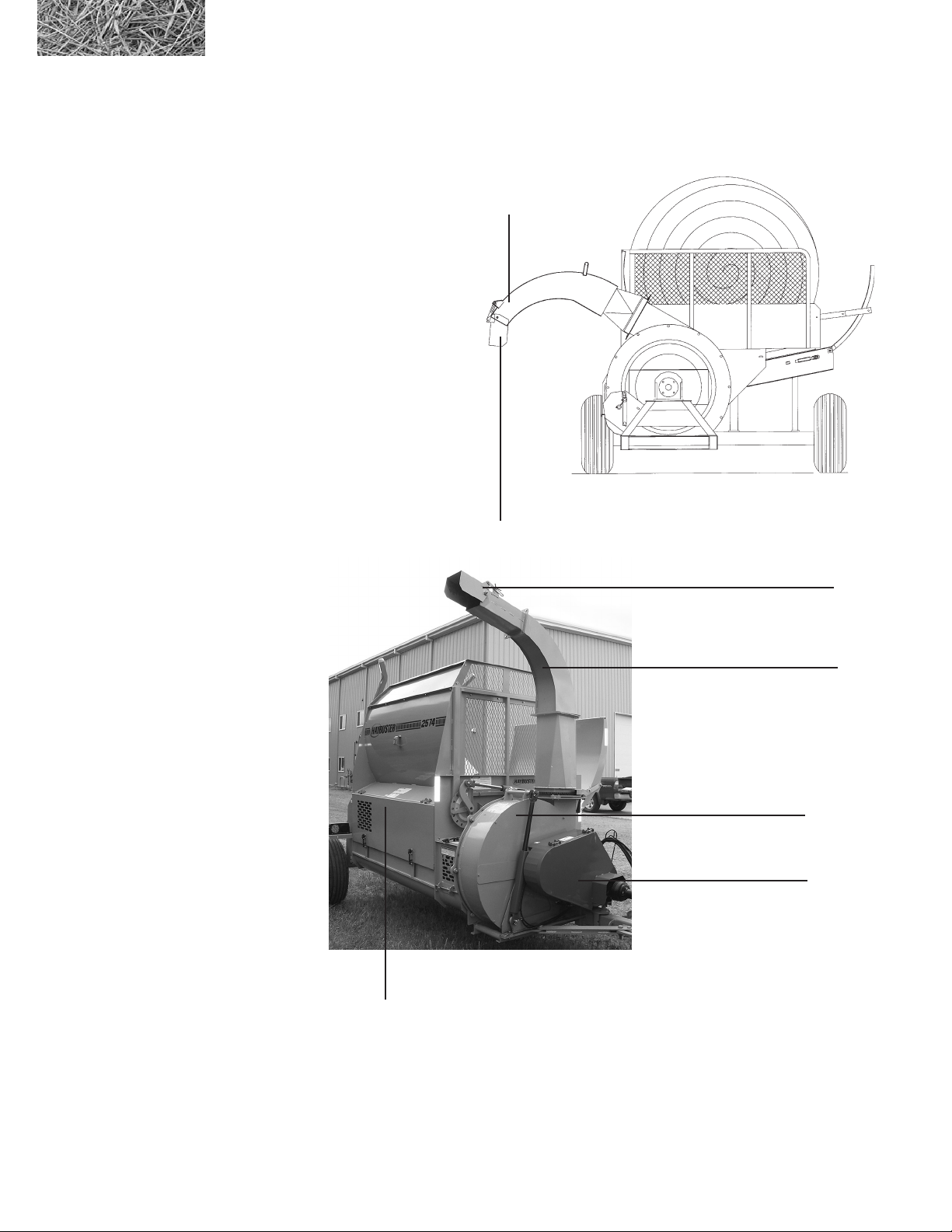
3.4.1 Changing the output distribution pattern
The spout and deector can be set to create a windrow or
for spreading.
For bedding or mulching, remove the spout assembly. This
allows the chopped material to discharge directly from the
fan. The distance the material is thrown and the coverage
may be varied by rotating the fan housing to obtain the
desired results. Adding the optional barrel will throw the
material farther.
For Bunk Feeding, set the spout in its working position.
Adjust the deector on the end of the spout up or down to
help regulate the force of the material leaving the spout.
When bunk feeding, raise the spout above the bunk and
use the deector to direct the material downward. This
will reduce the force, helping to prevent material from
blowing out of the bunk. If material is still blowing out of
the bunk, PTO speed may be decreased.
spout adjusted
to direct material
deector adjusted
to direct material
Figure 3.8
Spout, deector and
fan housing
fan housing
PTO Shield
auger and screen
access panel and shield
deector
spout
To create windrows set the spout and deector as follows; with the spout latched in the working position, the deector
can be raised and the fan housing rotated to place the material in a row as desired.
36
2574 BALEBUSTER OPERATING INSTRUCTIONS
Page 47
3.4.2 Changing length of cut
Using conveyor speed and slug bar settings to determine material size will reduce the horsepower requirements and
increase ail life. If a greater size reduction is required, then add a smaller screen.
Using a screen will produce a relatively small material size, but will require more horsepower, lower production (tons/
hour), and result in greater ail and screen wear.
3.4.3 Changing screens
Using a screen with a smaller hole will produce a ner cut.
Where a coarse cut is desired, use a screen with a larger hole.
To change screens, perform the following steps:
1. Open the access door on side of machine
2. Remove 8 bolts
3. Slide screen out
4. Clean screen track
5. Insert new screen
6. Replace bolts, and access door
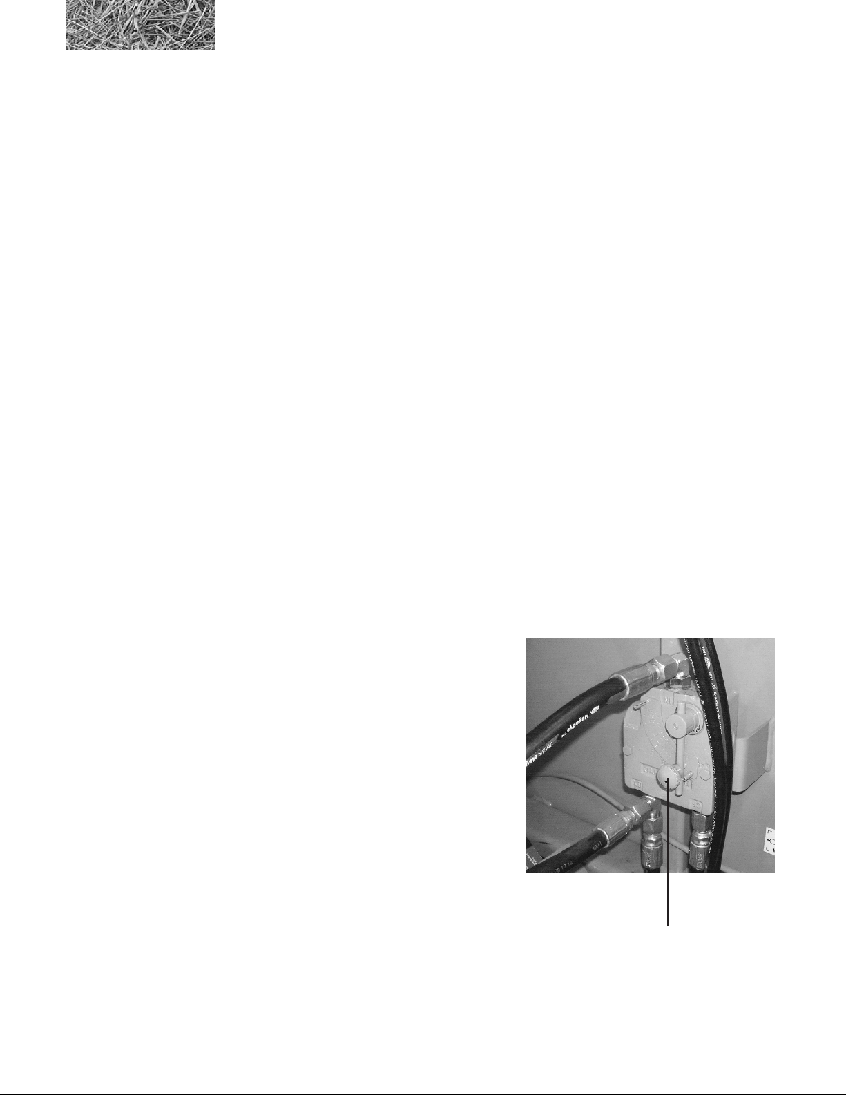
3.4.4 Adjusting the bale conveyor speed
Moving the lever counterclockwise will slow the conveyor,
and make a ner product.. Moving the lever clockwise
will speed up the conveyor and make a coarser product.
For tractors with PFC type hydraulic systems:
This valve should be set in the full open position. Conveyor speed can be controlled directly from the tractor
controls.
2574 BALEBUSTER OPERATING INSTRUCTIONS
bale conveyor speed
control valve
37
Page 48
3.4.5 Changing the slug bar settings
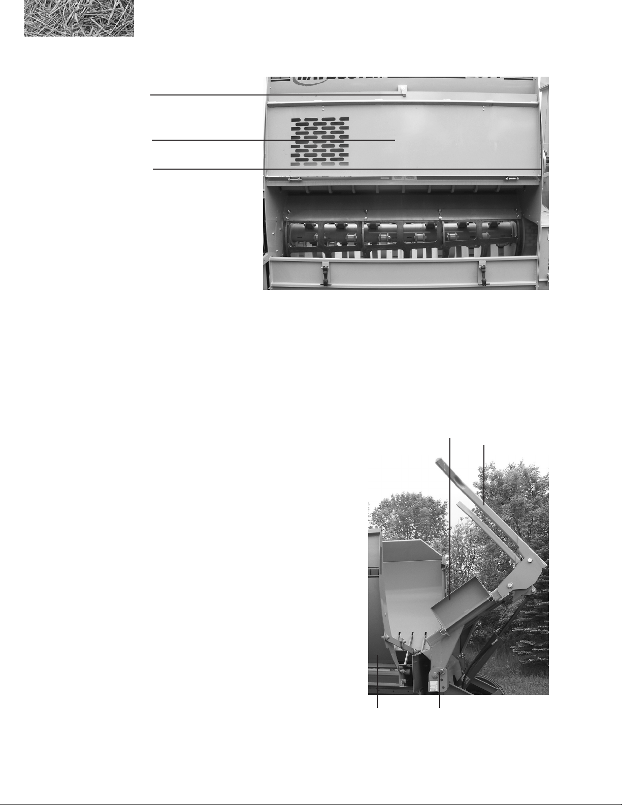
Figure 3.9
Location of the slug
bar ratchet
auger and screen access
panel and shield latch pin
auger and screen
access panel and shield
(open position)
slug bar ratchet
Exposing less ail will create a ner cut, while exposing more ail will create a coarser cut.
This is accomplished by adjusting the slug bar ratchet.
3.5 Road transport
3.5.1 Preparing the BALEBUSTER for transport
To prepare the machine for transport, perform the following steps:
1. Remove loader tines, and store them in the bale
chamber or in the transporting vehicle. Save the
bolts for later use.
2. Put loader frame in fully up position
3. Push up on links attaching rack to frame,
push rack into transport position
4. Check condition of tires
5. Check condition of SMV sign, warning lights,
safety chain, as required by local regulations.
6. Place loader wing in transport position.
Folding loader wing in
transport position
rack
loader transport pin in
transport position
loader tine
38
2574 BALEBUSTER OPERATING INSTRUCTIONS
Page 49

3.5.2 Changing Back To Operate
To prepare the machine for operation, perform the following steps:
1. To prevent serious personal injury enforce and
follow the safety precautions contained in this
manual
2. Hook up to tractor.
3. Lower loader frame.
4. Return rack to working position
3.6 Storage
3.6.1 Preparing the machine for storage
This machine is designed to fold for ease of transportation and storage. The rack assembly folds inside of bale
chamber.
To prepare the BALEBUSTER for storage, perform the following steps:
1. Shutdown the BALEBUSTER using the normal shutdown procedure.
2. Clean all mud, dirt, grease and other foreign material from the exterior of the machine. Cut all twine off
from around the rotor, auger, and fan. Wash the complete machine. If washing the BALEBUSTER with
a high pressure washer, keep the nozzle away from the sealed bearings. Repaint places where bare metal
is exposed - this will inhibit rusting.
3. Place the jackstands in the down and in locked position. Block the rear axle up taking the weight off the
tires, but do not deate tires. If possible, store the machine in a dry, protected place. If it is necessary to
store the machine outside, cover it with waterproof canvas, plastic, or other suitable protective material.
4. Coat exposed cylinder lift rod with grease. Oil chains on conveyor. Lubricate thoroughly according to
lubrication instructions. Repack wheel bearings.
6. Check the machine for any worn or broken parts.
By ordering parts now, you will avoid delays when it is time to remove the machine from storage. When ordering parts
always specify machine serial number and the part number of the replacement part. Part numbers can be found in the
parts section of this manual.
2574 BALEBUSTER OPERATING INSTRUCTIONS
39
Page 50

3.6.2 Removing the machine from storage
To remove the BALEBUSTER from storage, perform the following steps:
1. Remove all protective coverings.
2. Remove blocking from under the machine
3. Lubricate machine in accordance with lubrication instructions found in this manual.
4. Follow pre-starting inspection instructions.
40
2574 BALEBUSTER OPERATING INSTRUCTIONS
Page 51

Section 4: General maintenance
IMPORTANT: Before performing any service or maintenance on your BALEBUSTER, review the
safety guidelines for performing service and maintenance in section 1.6 “Safety review” under the
heading “WHEN PERFORMING SERVICE AND MAINTENANCE”.
4.1 Lubrication
LUBRICATION INSTRUCTIONS: The operator should make a check of all grease ttings in the unit before
beginning to operate it to become familiar with their location and the correct service schedule.
WARNING: Use normal shut-down procedure (section 3.3.4) before lubricating machine.
Use only a high quality, multi-purpose grease when lubricating the unit. Make sure all ttings and the nozzle of the
grease applicator are clean before applying the grease. If any grease ttings are missing, replace them immediately.
4.1.1 LUBRICATION POINTS
The following grease points will require a ten (10) hour service interval.
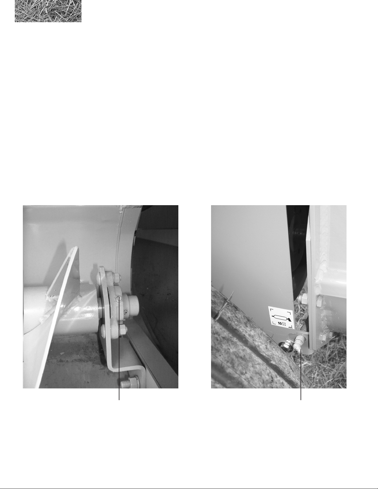
• Auger bearings – 2 places see gure 4.1
• Fan housing – 2 places see gure 4.2
• Fan pivot – 1 place see gure 4.2
• P.T.O. Universal joints -2 places see gure 4.3
• Telescoping shaft – 1 place
• Driveline supports – 2 places see gure 4.3
• Loader – 5 places see gure 4.4
• Conveyor – 2 places see gure 4.5
• Rotor bearings – 2 places see gure 4.6
The following grease points will require a forty (40) hour service interval.
• Hitch – 1 place see gure 4.3
2574 BALEBUSTER OPERATING INSTRUCTIONS
41
Page 52
To insure the best possible performance, all indicated locations should be greased as often as every ve (5) hours under
severe conditions. All grease points should be greased at equal intervals.
For the PTO shaft:
• As many as seven (7) pumps of grease are required to purge all cross and bearing grease points with fresh
grease.
• Telescoping members require enough grease to maintain a smooth sliding action. When telescoping
members become contaminated with dirty grease, they should be inspected and cleaned to insure smooth
operation.
• Shield components should be inspected to insure all components are in working condition or are replaced
if damaged. A properly maintained shield will inhibit dirt from contaminating telescoping members.
Figure 4.1
Lubrication points for
auger bearings
42
Auger bearing
lubrication point
2574 BALEBUSTER OPERATING INSTRUCTIONS
Auger bearing
lubrication point
Page 53
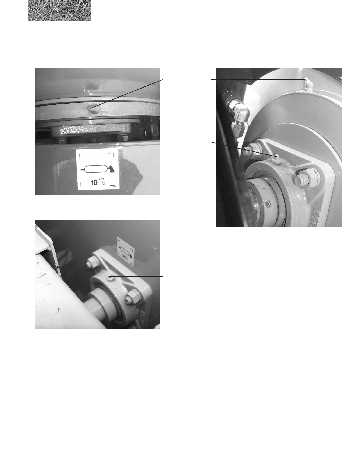
Figure 4.2
Lubrication points for
fan pivot, front & rear fan
housing
Fan pivot
lubrication point (1)
Front fan housing
lubrication point (1)
Rear fan housing
lubrication point
2574 BALEBUSTER OPERATING INSTRUCTIONS
43
Page 54
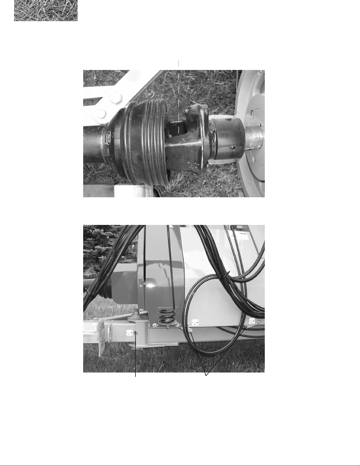
Figure 4.3
P.T.O., driveline supports,
and hitch lubrication points
P.T.O. universal joint
lubrication point
44
Hitch pivot
lubrication point
Driveline support bearings
lubrication points
2574 BALEBUSTER OPERATING INSTRUCTIONS
Page 55
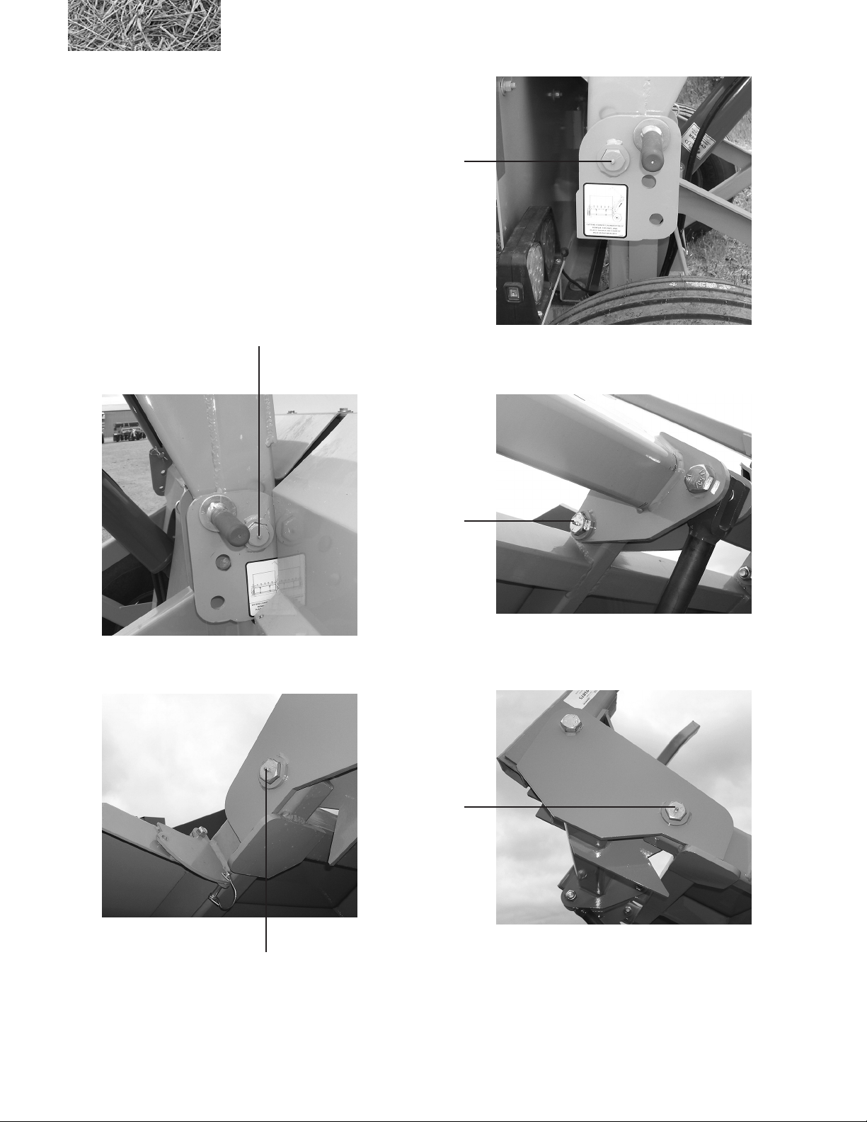
Figure 4.4
Lubrication points for
loader
Right lower loader pivot
lubrication point
Left lower loader pivot
lubrication point
Center upper
loader pivot
lubrication point
Right upper
loader pivot
lubrication point
Left upper loader pivot
lubrication point
2574 BALEBUSTER OPERATING INSTRUCTIONS
45
Page 56
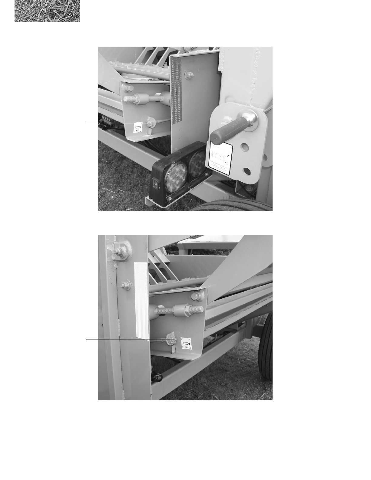
Figure 4.5
Lubrication points for
conveyor
Rear conveyor
lubrication point
46
Front conveyor
lubrication point
2574 BALEBUSTER OPERATING INSTRUCTIONS
Page 57
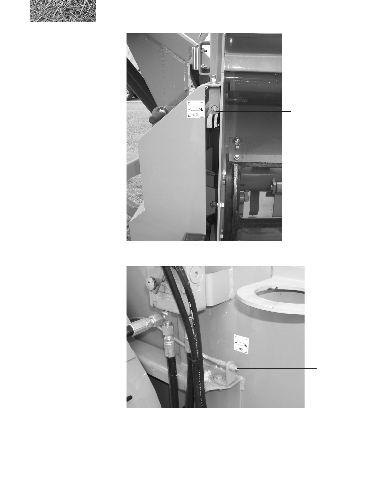
Figure 4.6
Lubrication points for rotor
Rotor
lubrication point
2574 BALEBUSTER OPERATING INSTRUCTIONS
Rotor
lubrication point
47
Page 58

4.2 Axle, wheels, tires
Repack wheel bearings annually.
4.3 Conveyor chain tension
See section 3.3.7 for instructions on how to adjust.
4.4 Belt Bushing Torque Settings
Location ft/lbs. m/kg
PTO shaft 83 11.5
Fan/Clutch 67 9.3
Rotor/Front 67 9.3
Rotor/Rear 30 4.1
Auger 30 4.1
Fan/Shaft 36 5.0
4.5 General appearance
Clean all mud, dirt, grease and other foreign material from the exterior of the machine. Cut all twine off from around
the rotor, auger, and fan. Wash the entire machine. If washing the BALEBUSTER with a high pressure washer, keep
the nozzle away from the sealed bearings. Repaint places where bare metal is exposed. - this will inhibit rusting.
48
2574 BALEBUSTER OPERATING INSTRUCTIONS
Page 59
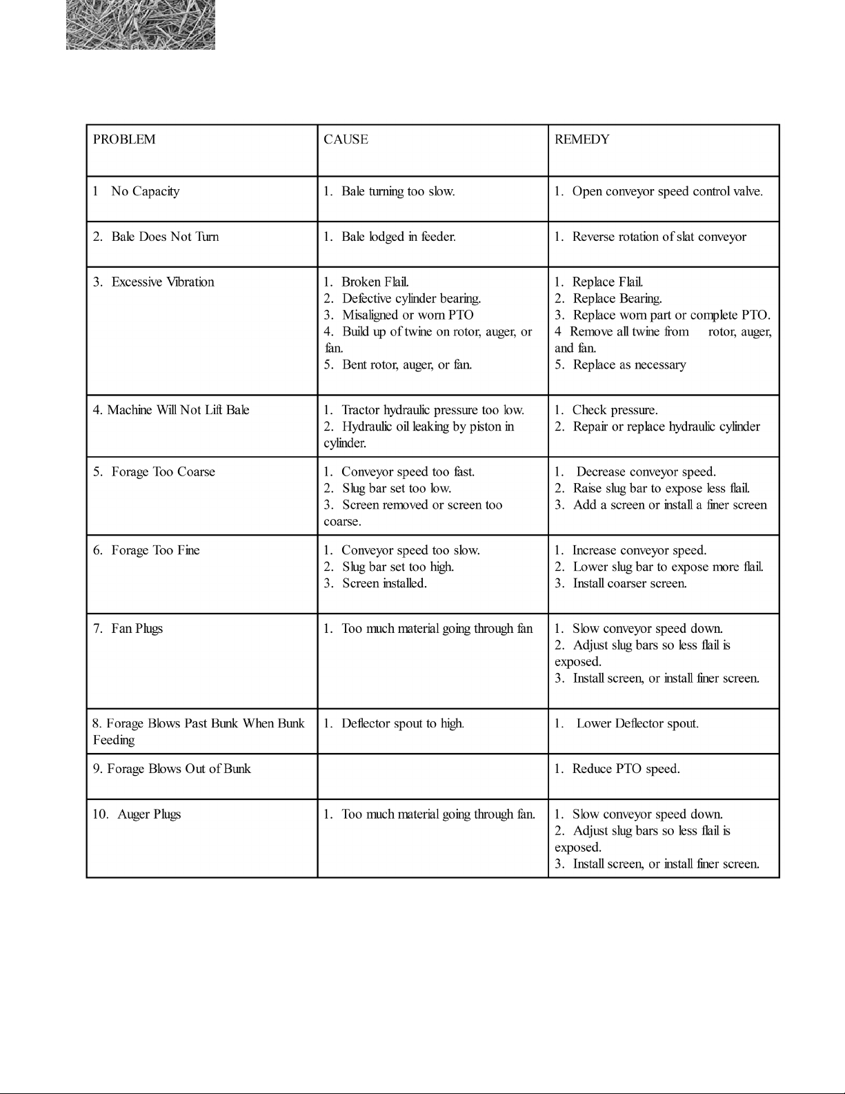
Section 5: Troubleshooting
2574 BALEBUSTER OPERATING INSTRUCTIONS
49
Page 60

Appendix A: WARRANTY
Duratech Industries International Inc. warrants to the original purchaser for one year from purchase date that this
product will be free from defects in material and workmanship when used as intended and under normal maintenance
and operating conditions. This warranty is limited to the replacement of any defective part or parts returned to our
factory in Jamestown, N.D., within thirty (30) days of failure.
This warranty shall become void if in DuraTech Industries International, Inc.’s., judgment the machine has been subject
to misuse, negligence, alterations, damaged by accident or lack of required normal maintenance, or if the product has
been used for a purpose for which it was not designed.
All claims for warranty must be made through the dealer which originally sold the product and all warranty adjustments
must be made through same.
This warranty does not apply to tires or bearings or any other trade accessories not manufactured by DuraTech
Industries International Inc.’s.. Buyer must rely solely on the existing warranty, if any, of these respective
manufactures.
DuraTech Industries International Inc., shall not be held liable for damages of any kind, direct, contingent, or
consequential to property under this warranty. DuraTech Industries International Inc., cannot be held liable for any
damages resulting form causes beyond its control. DuraTech Industries International Inc., shall not be held liable under
this warranty for loss of crops, or rental costs or any expense or loss for labor or supplies.
DuraTech Industries International Inc., reserves the right to make changes in material and/or designs of this product at
any time without notice.
All other warranties made with respect to this product, either expressed or implied, are hereby disclaimed by DuraTech
Industries International Inc.
50
2574 BALEBUSTER OPERATING INSTRUCTIONS
Page 61

AppendixB:2574BALEBUSTERSpecications
General:
Tractor H.P. required .................................. 100 HP (76.6 kw) to 155 HP (115.6 kw)
Capacity ........... 5-1/2’ long x 6-1/2’ diameter, 2000 lbs. (1.67 m x 1.98m, 907.2 kg)
Rotor Length ..........................................................................................78” (1.98 m)
Rotor Diameter(ail tip to ail tip) ............................................... 25-1/2” (64.8 cm)
Flails - Swinging / Heavy Spring Steele ............................................................... 40
Wheel - Taper Roller Bearings
PTO ...........................................................................................................1000 RPM
Dual Hydraulics (single hydraulic system optional) .......... 1500 PSI (105.6 kgf/cm
Tire Size .............................................................................. .......... See Appendix C
Cylinder .....................................4-1/2” x 24” (11.43 cm x 60.96 cm) Double Acting
Transport Position:
Height ..................................................................................................129” (3.26 m)
Width ....................................................................................................101” (2.57 m)
Length ...................................................................................................198” (5.02 m)
Weight ..................................................................................6325 Lbs. (2,868.97 kg)
2)
Working Positions:
Working Position 1 Bale Height ........................................................... 129” (3.26 m)
Length ...................................................................................................198” (5.02 m)
Width ....................................................................................................123” (3.12 m)
Working Position 2 Bales Height .........................................................129” (3.26 m)
Length ...................................................................................................271” (6.88 m)
Width ....................................................................................................123” (3.12 m)
2574 BALEBUSTER OPERATING INSTRUCTIONS
51
Page 62

Appendix C: Options
Hydraulic fan housing rotation, allows fan housing to be rotated “on the go”, requires 1 hydraulic valve and set of
outlets on tractor
Hydraulic fan discharge spout rotation, allows discharge spout to be rotated on the go, also requires 1 hydraulic valve
and set of outlets on tractor.
Cannon discharge spout, allows for spreading material over greater distance.
Screens available are: 4-1/4” x 10-1/2”
6-1/2” x 10-1/2”
“No Loader” If machine is to be loaded by front end loader or the like, the loader may not be needed.
Manual fan housing rotation
Curved spout - 80 degrees
Slugbars - Hydraulic
Tires: 31 X 10.5 X 15 “C” HWY - Standard
14L X 16.1 8 PLY FLOT IMP - Option
2nd Axle with highway tires
Shredder extension kit
Containment kit
52
2574 BALEBUSTER OPERATING INSTRUCTIONS
Page 63
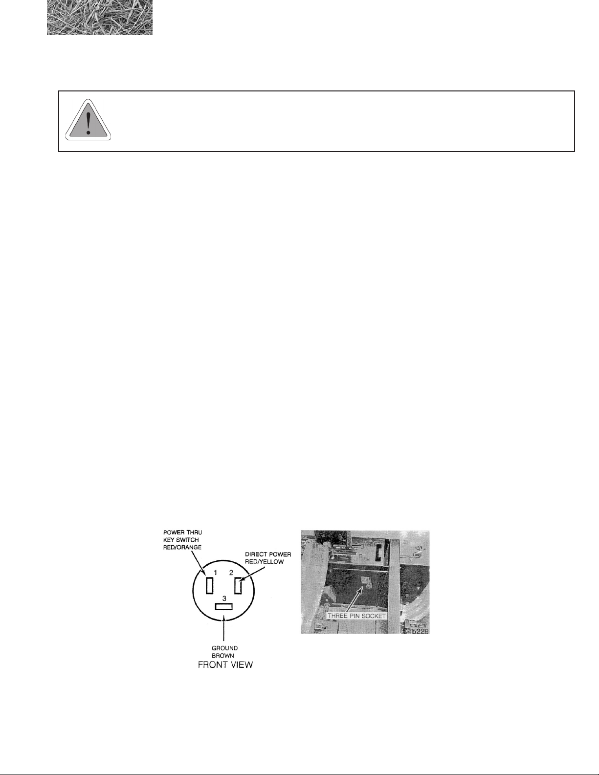
Appendix D: Required For Operation
WARNING: Do not operate the BALEBUSTER unless the tractor complies with the following
requirements:
1. Horsepower - 80 HP minimum. 1000 rpm, 1-3/8” PTO shaft.
2. Rollover protective structure and seat-belts.
3. Hydraulic system - 8 gallons per minute (30 liters per minute) minimum, 1500 Psi minimum (105 bar).
4. Two double acting control valves.
5. The tractor must be of equal or greater weight than the BALEBUSTER and bale to assure adequate
braking and steering control.
6. Counterbalance weight - It may be necessary to add weight to the front end of your tractor to maintain
adequate tractor stability and control. At least 20% of the total weight must remain on the front axle.
7. Tractor os setup according to section 3.3.1 “tractor setup”
8. 12V D.C. Auxiliary power socket on tractor.
Three Pin Socket
An auxiliary power connection is provided inside the operators compartment for connecting monitors, implement
controllers, C.B. radios and other 12-volt equipment.
The three pin outlet is located on the right hand side to the rear of the seat. The outlet has a ground terminal and two
12-volt power terminals. One power terminal is through the key switch and the other is direct power
2574 BALEBUSTER OPERATING INSTRUCTIONS
53
Page 64

Appendix E: 2574 BALEBUSTER SHIPPING LIST
PART# QUANTITY DESCRIPTION
4800471 2 BOLT\HEX\1X7\NC
4900127 2 NUT\TPLCK\1\NC
8101033 1 TINE\SQ\LEFTHAND
8101075 1 TINE\SQ\RIGHTHAND
1 CONTROL BOX CABLE ASSEMBLY
54
2574 BALEBUSTER OPERATING INSTRUCTIONS
Page 65

TM
2574
BALEBUSTER
TM
Part 2: Parts Reference
55
Page 66
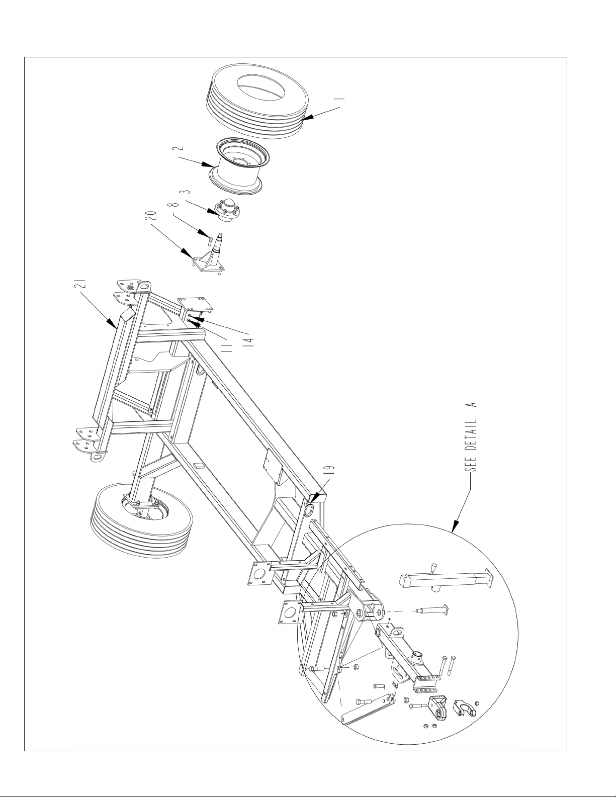
MAIN FRAME ASSEMBLY
56
2574 BALEBUSTER PARTS REFERENCE
Page 67

MAIN FRAME ASSEMBLY
ITEM PART NO. QTY. DESCRIPTION
1 2600041 2 9.5LX15 8 PLY TIRE
2 2600624 2 15 X 8 6 BOLT WHEEL
2600832 WHL\HWY-2\ASSY\31X10.5X15 (Includes 1 & 2)
3 2900171 2 HUB\6-BOLT\STUDS\COMPLETE
4 3800043 1 FTG\LUB\1/8MPXZRK\SHORT
5 4800056 1 PIN\HAIR\3/16(#3)
6 4800185 1 PIN\CLEVIS\1X3
7 4800248 2 BOLT\HEX\3/4X6
8 4800350 8 BOLT\HEX\5/8X2-1/4
9 4800562 1 BOLT\HEX\3/4X5\GR8\NC
10 4800647 2 BOLT\HEX\1X4\NC
11 4900005 8 NUT\HEX\5/8\NC
12 4900127 3 NUT\TPLCK\1\NC
13 4900139 3 NUT\TPLCK\3/4\GR8\NC
14 5000003 8 WASH\LOCK\5/8
15 5000014 1 WASH\FLAT\1
16 5800633 1 JACK\7000\SDWND\SQ\15”TRVL
17 7501047 1 HITCH\BASE\#3\PPI\1”PIN
18 7501048 1 HITCH\CLEVIS\PPI\1”PIN
19 7501069 2 GRMT\RBBR\2X1.75IDX1/4T
20 8101828 2 SPNDL\BOLT-ON
21 8101953 1 MNFRM\2574
22 8101954 1 HITCH\SWING\2574
23 8101971 1 BRACE\HITCH\2574
24 8102121 1 PIN\HITCH\SWING\MNFRM
2574 BALEBUSTER PARTS REFERENCE
57
Page 68
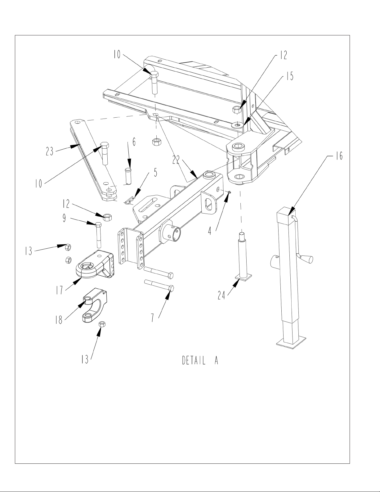
MAIN FRAME ASSEMBLY - DETAIL A
58
2574 BALEBUSTER PARTS REFERENCE
Page 69

MAIN FRAME ASSEMBLY - DETAIL A
ITEM PART NO. QTY. DESCRIPTION
1 2600041 2 9.5LX15 8 PLY TIRE
2 2600624 2 15 X 8 6 BOLT WHEEL
2600832 WHL\HWY-2\ASSY\31X10.5X15 (Includes 1 & 2)
3 2900171 2 HUB\6-BOLT\STUDS\COMPLETE
4 3800043 1 FTG\LUB\1/8MPXZRK\SHORT
5 4800056 1 PIN\HAIR\3/16(#3)
6 4800185 1 PIN\CLEVIS\1X3
7 4800248 2 BOLT\HEX\3/4X6
8 4800350 8 BOLT\HEX\5/8X2-1/4
9 4800562 1 BOLT\HEX\3/4X5\GR8\NC
10 4800647 2 BOLT\HEX\1X4\NC
11 4900005 8 NUT\HEX\5/8\NC
12 4900127 3 NUT\TPLCK\1\NC
13 4900139 3 NUT\TPLCK\3/4\GR8\NC
14 5000003 8 WASH\LOCK\5/8
15 5000014 1 WASH\FLAT\1
16 5800633 1 JACK\7000\SDWND\SQ\15”TRVL
17 7501047 1 HITCH\BASE\#3\PPI\1”PIN
18 7501048 1 HITCH\CLEVIS\PPI\1”PIN
19 7501069 2 GRMT\RBBR\2X1.75IDX1/4T
20 8101828 2 SPNDL\BOLT-ON
21 8101953 1 MNFRM\2574
22 8101954 1 HITCH\SWING\2574
23 8101971 1 BRACE\HITCH\2574
24 8102121 1 PIN\HITCH\SWING\MNFRM
2574 BALEBUSTER PARTS REFERENCE
59
Page 70
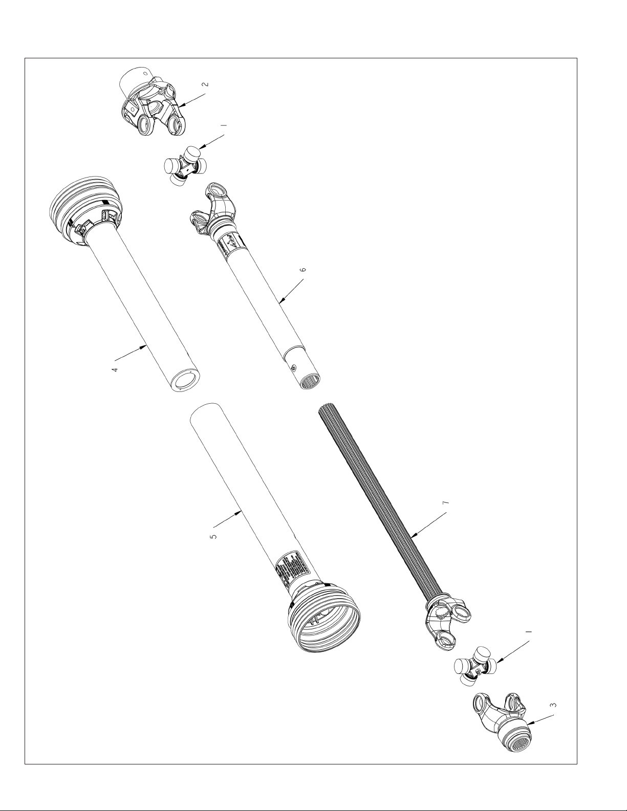
3600838 PTO
60
2574 BALEBUSTER PARTS REFERENCE
Page 71

3600838 PTO
ITEM PART NO. QTY. DESCRIPTION
3600838 1-3/4” PTO\55E\BALL-SHEAR
3600880 1-3/8” PTO\55E\BALL-SHEAR
1 3600820 2 CROSS & BEARING KIT\55E
2 3600877 1 YOKE\SHEAR\2-ID\55E
4800982 2 3/8X2 GRADE 2 SHEAR BOLT
3 3600536 YOKE\55\QD\CLR\1-3/4\20SP
3A 3600535 YOKE\55\QD\CLR\1-3/8\21SP
4 3600900 GUARD\INNER\3600838,3600839
5 3600902 GUARD\OUTER\3600838
3600878 1-3/4” PTO\HALF\TRACTOR (INCLUDES ITEMS 1,3,5,7)
3600881 1-3/8” PTO\HALF\TRACTOR (INCLUDES ITEMS 1,3,5,7)
3600876 PTO\HALF\MACHINE (INCLUDES ITEMS 1,2,4,6)
NOT SHOWN
4800326 1 SCR\SET\ALN\1/2X1/2\NC
4800323 1 SCR\SET\ALN\1/2X1\NC
6200061 1 KEY\SQ\1/2X2-1/4
2574 BALEBUSTER PARTS REFERENCE
61
Page 72
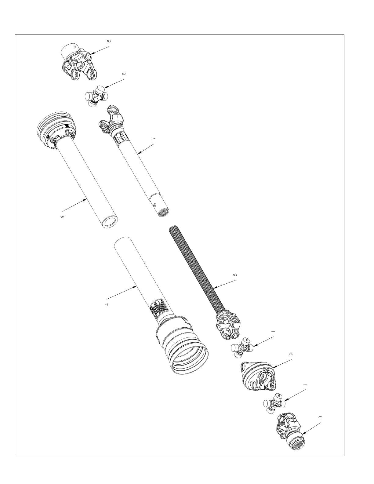
3600839 PTO
62
2574 BALEBUSTER PARTS REFERENCE
Page 73

3600839 PTO
ITEM PART NO. QTY. DESCRIPTION
3600839 1-3/4” PTO\55E\CAT6\WWCV
3600882 1-3/8” PTO\55E\CAT6\WWCV
1 3600764 2 CROSS&BRG\CAT6\80DEG\CV
2 3600765 1 CENTER-HOUSING
3 3600782 YOKE\WWCV\1-3/4\20SP\AL
3A 3600763 YOKE\CAT6\WWCV\1-3/8-21\AL
4 3600900 1 GUARD\INNER\3600838,3600839
6 3600820 CROSS & BEARING KIT\55E
8 3600877 1 YOKE\SHEAR\2-ID\55E
4800982 2 3/8X2 GRADE 2 SHEAR BOLT
9 3600901 1 GUARD\OUTER\3600839
3600875 1-3/4” PTO\HALF\TRACTOR (INCLUDES ITEMS 1,2,3,4,5)
3600883 1-3/8” PTO\HALF\TRACTOR (INCLUDES ITEMS 1,2,3,4,5)
3600876 PTO\HALF\MACHINE (INCLUDES ITEMS 6,7,8,9)
NOT SHOWN
4800326 1 SCR\SET\ALN\1/2X1/2\NC
4800323 1 SCR\SET\ALN\1/2X1\NC
6200061 1 KEY\SQ\1/2X2-1/4
2574 BALEBUSTER PARTS REFERENCE
63
Page 74
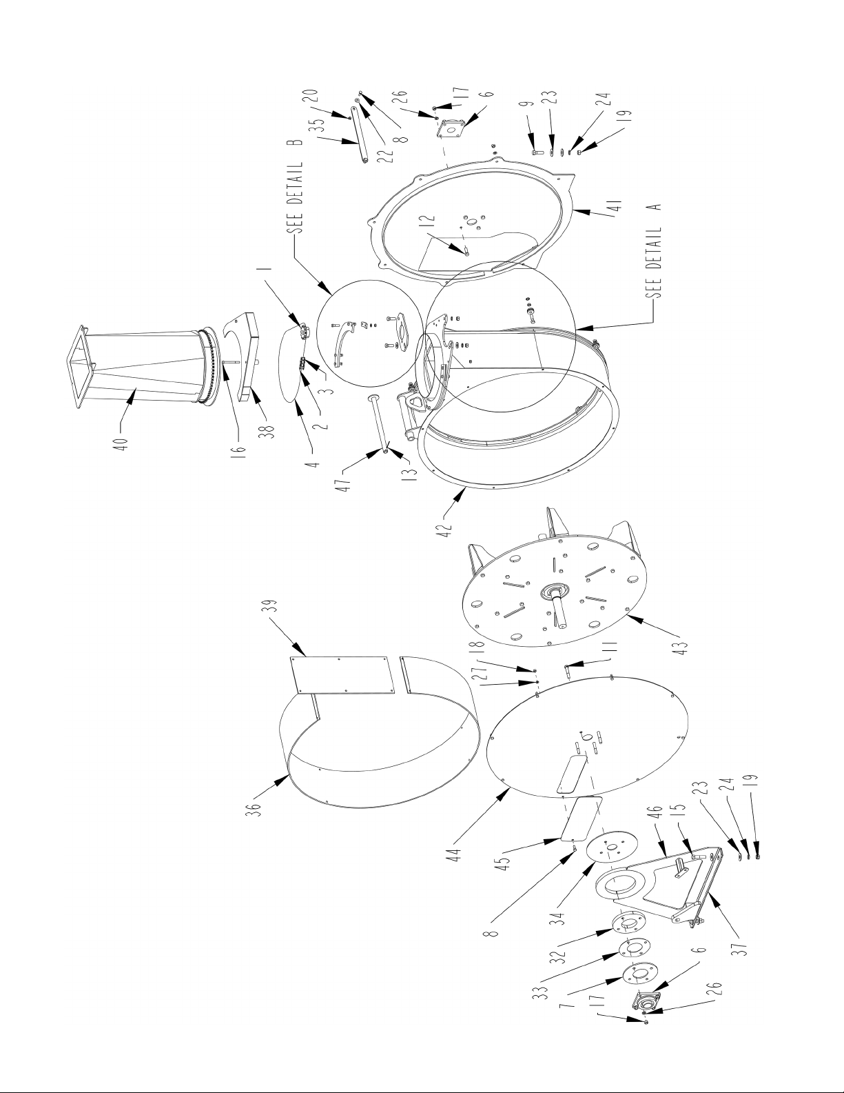
FAN ASSEMBLY
64
2574 BALEBUSTER PARTS REFERENCE
Page 75

FAN ASSEMBLY
ITEM PART NO. QTY. DESCRIPTION
1 1000129 1 SPKT\60\B\12\1\1/4KW
2 1100062 1 CHAIN\60\CL
3 1100063 1 CHAIN\60\OL
4 1100270 1 CHAIN\60\77
5 2000080 7 BRG\CAM\1/2” I.D.X1-1/2” O.D
6 2000311 2 BRG\FLG\CAST\1-3/4\4BOLT
7 4500529 1 PL\MNT\FAN
8 4800003 10 BOLT\HEX\3/8X1
9 4800010 2 BOLT\HEX\5/8X2
10 4800034 8 BOLT\HEX\3/8X1-1/2
11 4800068 4 BOLT\HEX\1/2X3
12 4800082 6 BOLT\HEX\1/2X1-1/2
13 4800172 1 PIN\COT\1/8X2
14 4800178 7 BOLT\HEX\1/2X1-3/4
15 4800196 2 BOLT\HEX\5/8X2-3/4
16 4800516 2 BOLT\HEX\3/8X3-3/4/NC
17 4900001 17 NUT\HEX\1/2\NC
18 4900002 18 NUT\HEX\3/8\NC
19 4900005 4 NUT\HEX\5/8\NC
20 4900023 2 NUT\TPLCK\3/8\NC
21 4900046 7 NUT\JAM\1/2\NC
22 5000001 10 WASH\FLAT\3/8
23 5000002 8 WASH\FLAT\5/8
24 5000003 4 WASH\LOCK\5/8
25 5000004 2 WASH\FLAT\1/2
26 5000006 17 WASH\LOCK\1/2
27 5000019 18 WASH\LOCK\3/8
28 5000134 7 WASH\LOCK\TOOTH\INT\1/2
29 8100542 1 MNT\MTR\ORBIT\FAN
30 8101663 2 DBLR\MNT\SWVL\FAN
31 8101664 4 MNT\SWVL\FAN
32 8101665 1 MNT\PL\FAN\3/4”
33 8101666 1 MNT\PL\FAN
34 8101695 1 MNT\PL\FAN
35 8101697 1 BRACE\FAN
36 8101720 1 SHT\LINER\FAN
37 8101735 1 SHIM\MNT\FAN\10GA
38 8101754 1 SHLD\CHN\RTT\FAN-TRANS
39 8101772 1 LNR\SPT\HSG\FAN
40 8101847 1 TRANS\FAN
41 8101975 1 HSG\FAN\REAR
42 8101995 1 HSG\FAN\W/LINER
43 8101997 1 FAN\ASSY\REPLCB\FINS-SHAFT
44 8102001 1 SH\HSG\FAN
45 8102002 1 CVR\ACT\FAN
46 8102044 1 MNT\FRONT\FAN\2574
47 8102135 1 PIN\CYL\FAN\2574
2574 BALEBUSTER PARTS REFERENCE
65
Page 76
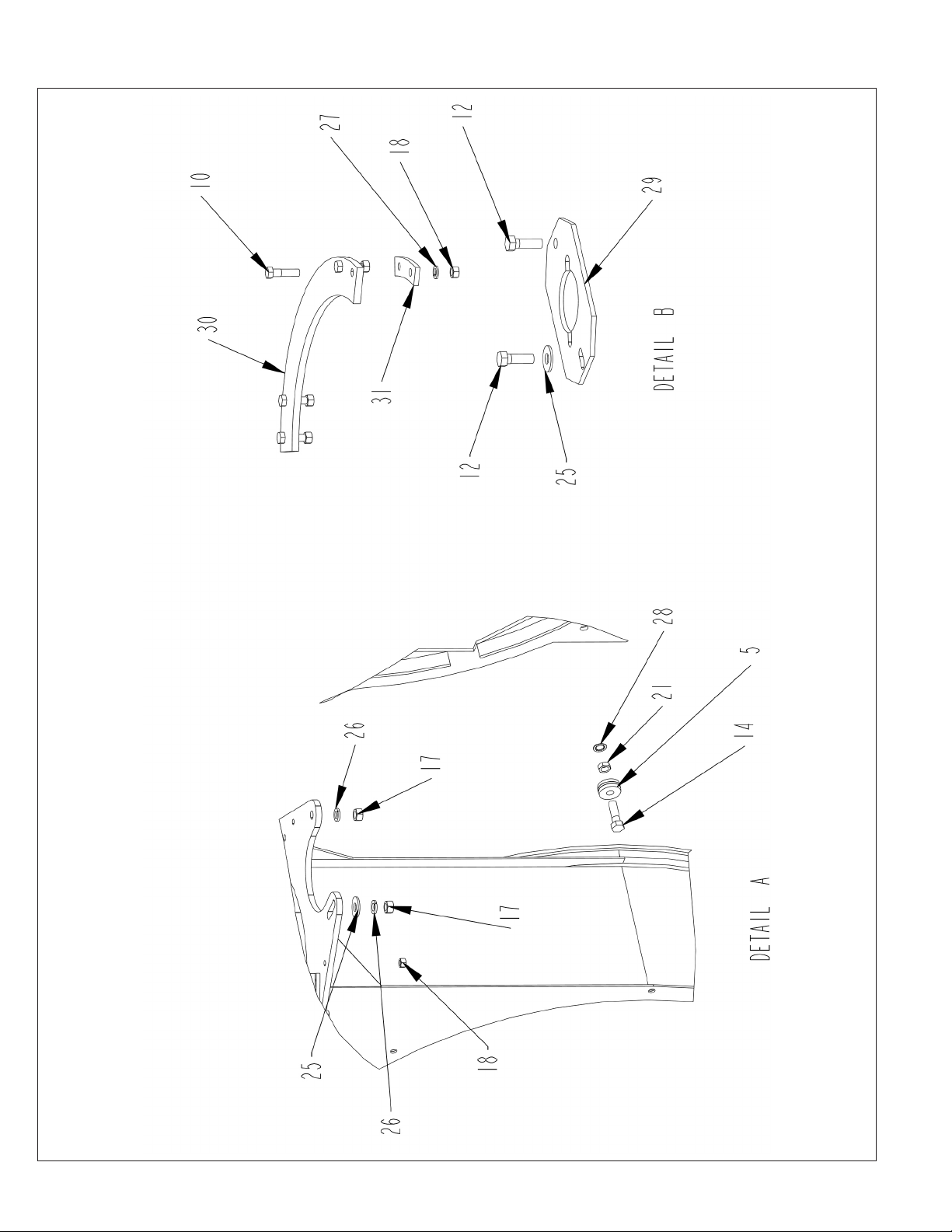
FAN ASSEMBLY - DETAILS A AND B
66
2574 BALEBUSTER PARTS REFERENCE
Page 77

FAN ASSEMBLY - DETAILS A AND B
ITEM PART NO. QTY. DESCRIPTION
1 1000129 1 SPKT\60\B\12\1\1/4KW
2 1100062 1 CHAIN\60\CL
3 1100063 1 CHAIN\60\OL
4 1100270 1 CHAIN\60\77
5 2000080 7 BRG\CAM\1/2” I.D.X1-1/2” O.D
6 2000311 2 BRG\FLG\CAST\1-3/4\4BOLT
7 4500529 1 PL\MNT\FAN
8 4800003 10 BOLT\HEX\3/8X1
9 4800010 2 BOLT\HEX\5/8X2
10 4800034 8 BOLT\HEX\3/8X1-1/2
11 4800068 4 BOLT\HEX\1/2X3
12 4800082 6 BOLT\HEX\1/2X1-1/2
13 4800172 1 PIN\COT\1/8X2
14 4800178 7 BOLT\HEX\1/2X1-3/4
15 4800196 2 BOLT\HEX\5/8X2-3/4
16 4800516 2 BOLT\HEX\3/8X3-3/4/NC
17 4900001 17 NUT\HEX\1/2\NC
18 4900002 18 NUT\HEX\3/8\NC
19 4900005 4 NUT\HEX\5/8\NC
20 4900023 2 NUT\TPLCK\3/8\NC
21 4900046 7 NUT\JAM\1/2\NC
22 5000001 10 WASH\FLAT\3/8
23 5000002 8 WASH\FLAT\5/8
24 5000003 4 WASH\LOCK\5/8
25 5000004 2 WASH\FLAT\1/2
26 5000006 17 WASH\LOCK\1/2
27 5000019 18 WASH\LOCK\3/8
28 5000134 7 WASH\LOCK\TOOTH\INT\1/2
29 8100542 1 MNT\MTR\ORBIT\FAN
30 8101663 2 DBLR\MNT\SWVL\FAN
31 8101664 4 MNT\SWVL\FAN
32 8101665 1 MNT\PL\FAN\3/4”
33 8101666 1 MNT\PL\FAN
34 8101695 1 MNT\PL\FAN
35 8101697 1 BRACE\FAN\2564
36 8101720 1 SHT\LINER\FAN
37 8101735 1 SHIM\MNT\FAN\10GA
38 8101754 1 SHLD\CHN\RTT\FAN-TRANS
39 8101772 1 LNR\SPT\HSG\FAN
40 8101847 1 TRANS\FAN
41 8101975 1 HSG\FAN\REAR
42 8101994 1 HSG\FAN\TOP
43 8101997 1 FAN\ASSY\REPLCB\FINS-SHAFT
44 8102001 1 SH\HSG\FAN
45 8102002 1 CVR\ACT\FAN
46 8102044 1 MNT\FRONT\FAN\2574
47 8102135 1 PIN\CYL\FAN\2574
2574 BALEBUSTER PARTS REFERENCE
67
Page 78
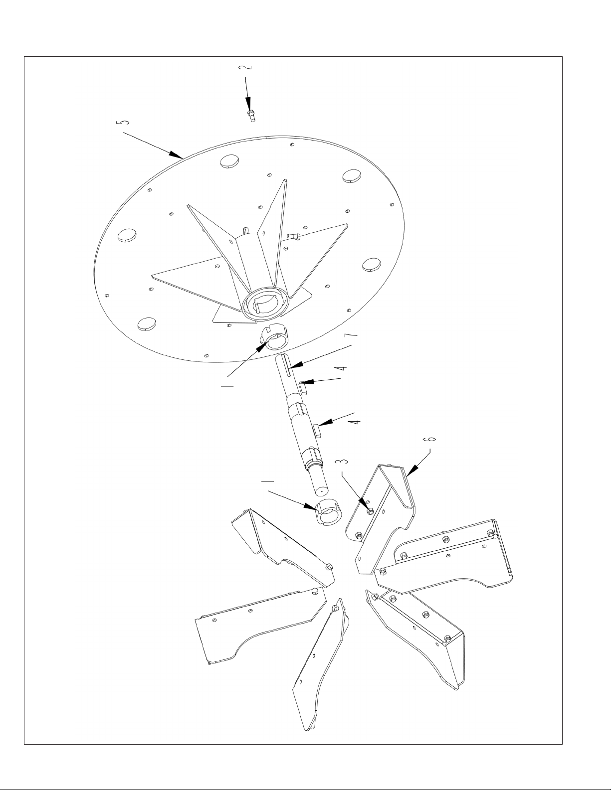
FAN ASSEMBLY - REPLACEABLE FIN AND SHAFT
68
2574 BALEBUSTER PARTS REFERENCE
Page 79

FAN ASSEMBLY - REPLACEABLE FIN AND SHAFT
ITEM PART NO. QTY. DESCRIPTION
1 1400847 2 BUSH\2517\2-7/16
2 4800628 24 BOLT\HEX\1/2X1-1/4\GR8\NC
3 4900014 24 NUT\TPLCK\1/2\NC
4 6200098 2 KEY\REC\1/2X5/8X2
5 8101836 1 RTR\FAN\BOLT-ON\FIN\SHAFT
6 8101998 6 MNT\FIN\REPLACEABLE
7 8102000 1 SHFT\RTR\FAN (THRU S.N. 0051)
7A 8102166 SHFT\RTR\FAN (S.N. 0052 & UP)
8101997 FAN\ASSY\REPLCB\FINS
2574 BALEBUSTER PARTS REFERENCE
69
Page 80
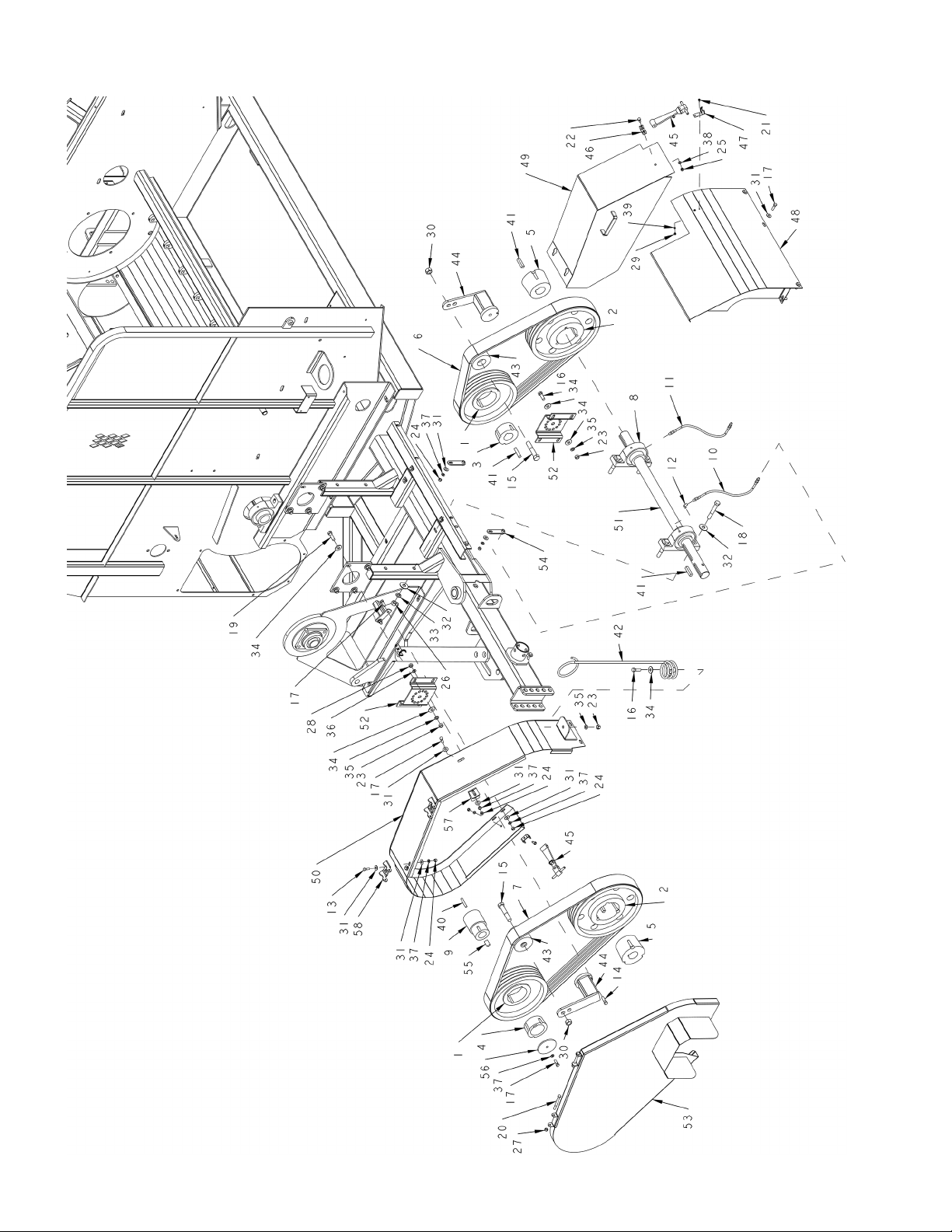
DRIVE ASSEMBLY
70
2574 BALEBUSTER PARTS REFERENCE
Page 81

DRIVE ASSEMBLY
ITEM PART NO. QTY. DESCRIPTION
1 1400840 2 SHVE\5V-4\12.5\TB
2 1400841 2 SHVE\5V-4\15.0\TB
3 1400844 1 BUSH\A2\2
4 1400845 1 BUSH\A2\3
5 1400846 2 BUSH\B3\2
6 1600111 1 V-BELT\5VX\4\90.0
7 1600112 1 V-BELT\5VX\4\100.0
8 2000510 3 BRG\PB\2\2BOLT
9 3600837 1 CLUTCH\OVERRUNNING\CW (THRU S.N. 0051)
9A 3600898 CLUTCH\OVERRUNNING\CW\5-1/4” L (S.N. 0052 & UP)
10 3700830 1 HOSE\LUB\1/8X16\MPS-MPS
11 3700830 1 HOSE\LUB\1/8X16\MPS-MPS
12 3800111 1 FTG\1/8MPX1/8FP\90\ST;EL
13 4800003 4 BOLT\HEX\3/8X1
14 4800040 2 BOLT\HEX\7/16X1-1/2
15 4800063 2 BOLT\HEX\3/4X4
16 4800082 8 BOLT\HEX\1/2X1-1/2
17 4800098 13 BOLT\HEX\3/8X1-1/4\NC
18 4800100 4 BOLT\HEX\5/8X4
19 4800178 1 BOLT\HEX\1/2X1-3/4
20 4800197 2 BOLT\HEX\3/8X3-1/2
21 4800468 4 SCR\RD\SLOT\#10-24X1/2\NC
22 4800643 2 BOLT\HEX\5/16X3/4
23 4900001 9 NUT\HEX\1/2\NC
24 4900002 16 NUT\HEX\3/8\NC
25 4900003 2 NUT\HEX\5/16\NC
26 4900005 4 NUT\HEX\5/8\NC
27 4900023 2 NUT\TPLCK\3/8\NC
28 4900025 2 NUT\HEX\7/16\NC
29 4900072 4 NUT\HEX\#10\NC
30 4900139 2 NUT\TPLCK\3/4\GR8\NC
31 5000001 30 WASH\FLAT\3/8
32 5000002 8 WASH\FLAT\5/8
33 5000003 4 WASH\LOCK\5/8
34 5000004 17 WASH\FLAT\1/2
35 5000006 9 WASH\LOCK\1/2
36 5000015 2 WASH\LOCK\7/16
37 5000019 17 WASH\LOCK\3/8
38 5000022 2 WASH\LOCK\5/16
39 5000071 4 WASH\LOCK;EXT\STAR\#10
40 6200021 1 KEY\SQ\3/8X1-1/2\HARDEND (THRU S.N. 0051)
40A 6200020 KEY\SQ\3/8X2-1/4\HARDEND (S.N. 0052 & UP)
41 6200061 4 KEY\SQ\1/2X2-1/4
42 7500170 1 HOSE MINDER
43 7501616 2 IDLER\BELT\STEEL\3.5”WIDE
44 7501617 2 TNSR\BELT\SE38
45 7501660 2 LATCH\RBBR\8\W-STD-CATCH
46 7501660 2 LATCH\RBBR\8\W-STD-CATCH
47 7501660 2 LATCH\RBBR\8\W-STD-CATCH
48 8101984 1 SHLD\DRV\MDDL\FRNT\2574
49 8101985 1 SHLD\DRV\RTR\
50 8101986 1 SHLD\DRV\FAN
51 8101996 1 SHFT\DRV\BLT
52 8102116 2 MNT\TNSR\BELT
53 8102122 1 SHLD\DRV\FAN\2574
54 8102125 2 MNT\LINE\GREASE\
55 8102136 1 KEY\STEP\CLUTCH\FAN\2574
56 8102137 1 DISK\RETAINER\FAN\2574
57 8102139 1 MNT\SHLD\DRV\FAN
58 8102157 2 HINGE\SHLD\2574
NOT SHOWN
8102154 WRENCH\OPEN END\2-1/8 (AUGER DRIVE)
8102155 WRENCH\OPEN END\2-3/4 (FAN)
2574 BALEBUSTER PARTS REFERENCE
71
Page 82
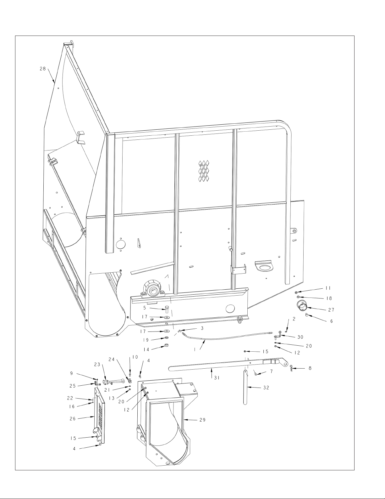
SHREDDER ASSEMBLY FRONT
72
2574 BALEBUSTER PARTS REFERENCE
Page 83

SHREDDER ASSEMBLY FRONT
ITEM PART NO. QTY. DESCRIPTION
1 3701578 1 HOSE\LUB\1/8X33\MPS-MPS
2 3800043 1 FTG\LUB\1/8MPXZRK\SHORT
3 3800111 1 FTG\1/8MPX1/8FP\90\ST;EL
4 4800003 8 BOLT\HEX\3/8X1
5 4800033 4 BOLT\HEX\3/4X2
6 4800085 1 BOLT\HEX\1/2X1
7 4800098 1 BOLT\HEX\3/8X1-1/4\NC
8 4800107 1 PIN\HAIR\1/8(#9)
9 4800468 2 SCR\RD\SLOT\#10-24X1/2\NC
10 4800643 1 BOLT\HEX\5/16X3/4
11 4900001 1 NUT\HEX\1/2\NC
12 4900002 7 NUT\HEX\3/8\NC
13 4900003 1 NUT\HEX\5/16\NC
14 4900004 4 NUT\HEX\3/4\NC
15 4900023 3 NUT\TPLCK\3/8\NC
16 4900072 2 NUT\HEX\#10\NC
17 5000005 8 WASH\FLAT\3/4
18 5000006 1 WASH\LOCK\1/2
19 5000012 4 WASH\LOCK\3/4
20 5000019 7 WASH\LOCK\3/8
21 5000022 1 WASH\LOCK\5/16
22 5000071 2 WASH\LOCK;EXT\STAR\#10
23 7501660 1 LATCH\RBBR\8\W-STD-CATCH
24 7501660 1 LATCH\RBBR\8\W-STD-CATCH
25 7501660 1 LATCH\RBBR\8\W-STD-CATCH
26 8101282 1 DOOR\AUGER EX
27 8101748 1 BRKT\STRG\JACK
28 8101973 1 FRM\SHREDDER\2574
29 8101974 1 AUGER\EXT
30 8102124 1 MNT\LINE\GREASE
31 8102133 1 HANDLE\RACK\2574
32 8102134 1 LEG\TOOL\RACK
2574 BALEBUSTER PARTS REFERENCE
73
Page 84
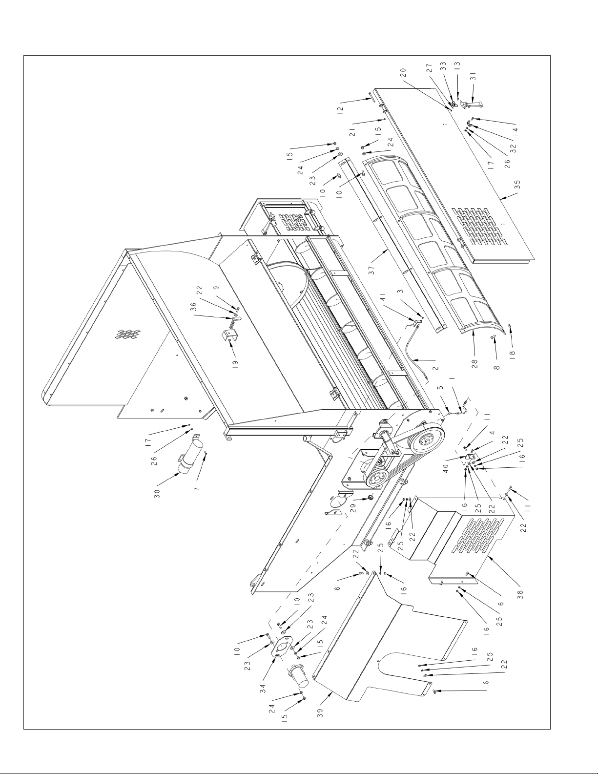
SHREDDER ASSEMBLY - SHIELDS, DOOR, & SCREEN
74
2574 BALEBUSTER PARTS REFERENCE
Page 85

SHREDDER ASSEMBLY - SHIELDS, DOOR, & SCREEN
ITEM PART NO. QTY. DESCRIPTION
1 3700770 1 HOSE\LUB\1/8X8-1/2\MPS-MPS
2 3701487 1 HOSE\LUB\1/8X27.25\MPS-MPS
3 3800043 1 FTG\LUB\1/8MPXZRK\SHORT
4 3800135 1 FTG\LUB\1/8MPXZRK\45D\LW
5 3800244 1 FTG\1/8MPX1/8FP\45
6 4800003 11 BOLT\HEX\3/8X1
7 4800013 2 BOLT\HEX\5/16X1
8 4800018 4 BOLT\HEX\1/2X1-1/4
9 4800034 1 BOLT\HEX\3/8X1-1/2
10 4800082 12 BOLT\HEX\1/2X1-1/2
11 4800098 2 BOLT\HEX\3/8X1-1/4\NC
12 4800198 2 BOLT\HEX\5/16X3-3/4
13 4800468 4 SCR\RD\SLOT\#10-24X1/2\NC
14 4800643 2 BOLT\HEX\5/16X3/4
15 4900001 12 NUT\HEX\1/2\NC
16 4900002 14 NUT\HEX\3/8\NC
17 4900003 2 NUT\HEX\5/16\NC
18 4900014 4 NUT\TPLCK\1/2\NC
19 4900023 1 NUT\TPLCK\3/8\NC
20 4900072 4 NUT\HEX\#10\NC
21 4900099 2 NUT\TPLCK\5/16\GR8\NC
22 5000001 16 WASH\FLAT\3/8
23 5000004 10 WASH\FLAT\1/2
24 5000006 12 WASH\LOCK\1/2
25 5000019 14 WASH\LOCK\3/8
26 5000022 2 WASH\LOCK\5/16
27 5000071 4 WASH\LOCK;EXT\STAR\#10
28 SEE SCREEN LIST BELOW
29 7500743 2 GRMT\RBBR\1-3/8X1IDX1/4T
30 7501628 1 CNSTRS\MANUAL\12X3.5
31 7501660 2 LATCH\RBBR\8\W-STD-CATCH
32 7501660 2 LATCH\RBBR\8\W-STD-CATCH
33 7501660 1 LATCH\RBBR\8\W-STD-CATCH
34 8100036 1 MNT\MTR\HYD
35 8101281 1 DOOR\SHREADER
36 8101678 1 LATCH\DOOR
37 8101702 1 MNT\SCRN\BTTM\SHREDDER
38 8102008 1 SHLD\AUGER\2574
39 8102027 1 SHLD\REAR\SHRDR\FLL
40 8102123 1 MNT\LINE\GREASE
41 8102124 1 MNT\LINE\GREASE
SCREENS
5400128 SCRN\4-1/4X10-1/2
5400129 SCRN\6-1/2X10-1/2
5400135 SCRN\2HL\1/4 ROUND
5400136 SCRN\3HL\1/4 ROUND
5400137 SCRN\4HL\1/4 ROUND
2574 BALEBUSTER PARTS REFERENCE
75
Page 86
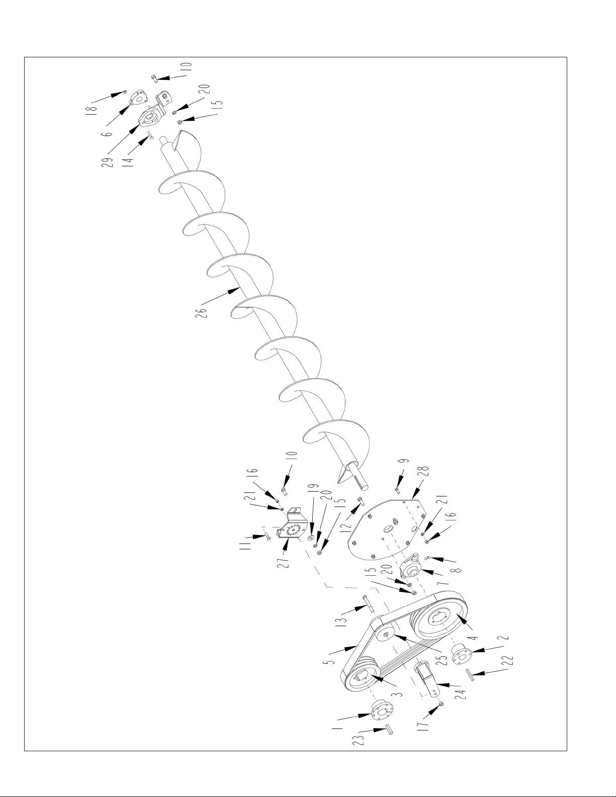
AUGER ASSEMBLY
76
2574 BALEBUSTER PARTS REFERENCE
Page 87

AUGER ASSEMBLY
ITEM PART NO. QTY. DESCRIPTION
1 1400578 1 BUSH\QD\SF\2
2 1400582 1 BUSH\Q1\1-1/2
3 1400842 1 SHVE\5V-3\7.4\SF
4 1400850 1 SHVE\5V-3\11.8\SF
5 1600117 1 V-BELT\5VX\3\75.0
6 2000302 1 BRG\FLG\CAST\1-1/4\3BOLT
7 2000308 1 BRG\FLG\CAST\1-1/2\2BOLT
8 3800244 1 FTG\1/8MPX1/8FP\45
9 4800003 6 BOLT\HEX\3/8X1
10 4800018 4 BOLT\HEX\1/2X1-1/4
11 4800034 1 BOLT\HEX\3/8X1-1/2
12 4800082 2 BOLT\HEX\1/2X1-1/2
13 4800188 1 BOLT\HEX\1/2X4
14 4800476 3 BOLT\CRG\5/16X1-3/4\NC
15 4900001 6 NUT\HEX\1/2\NC
16 4900002 7 NUT\HEX\3/8\NC
17 4900014 1 NUT\TPLCK\1/2\NC
18 4900108 3 NUT\FLG\SERR\5/16\NC
19 5000004 2 WASH\FLAT\1/2
20 5000006 6 WASH\LOCK\1/2
21 5000019 7 WASH\LOCK\3/8
22 6200026 1 KEY\SQ\3/8X3
23 6200061 1 KEY\SQ\1/2X2-1/4
24 7501601 1 TNSR\BELT\SE27
25 7501602 1 IDLER\BELT\STEEL\3.5”WIDE
26 8101979 1 AUGER
27 8102063 1 MNT\TNSR\BELT
28 8102132 1 HSG\END\AUGER-PAN\2564
29 8102344 1 MNT\BRG\AUGER\W-TWINEGUARD
2574 BALEBUSTER PARTS REFERENCE
77
Page 88
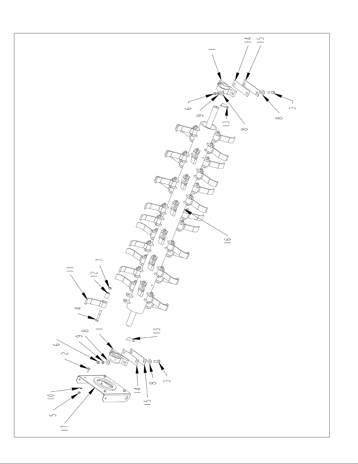
ROTOR ASSEMBLY
78
2574 BALEBUSTER PARTS REFERENCE
Page 89

ROTOR ASSEMBLY
ITEM PART NO. QTY. DESCRIPTION
1 2000510 2 BRG\PB\2\2BOLT
2 4800018 4 BOLT\HEX\1/2X1-1/4
3 4800079 4 BOLT\HEX\5/8X2-1/2
4 4800598 40 BOLT\HEX\5/8X4\NF\GR8
5 4900001 4 NUT\HEX\1/2\NC
6 4900005 4 NUT\HEX\5/8\NC
7 4900179 40 NUT\TPLCK\5/8\GR9\NF
8 5000002 8 WASH\FLAT\5/8
9 5000003 4 WASH\LOCK\5/8
10 5000006 4 WASH\LOCK\1/2
11 5200012 40 FLAIL\BB\8
12 7500223 40 BUSH\FLAIL\1-1/4X.687x2-1/8L
13 7501050 2 PLATE\SICKLE
14 8101462 2 SHM\16GA\BRG\RTR
15 8101631 2 SHM\10GA\BRG\RTR
16 8101989 1 RTR\FLAIL\2”SHFT\HVY
17 8102138 1 BRKT\BRG\2”\REAR\RTR
2574 BALEBUSTER PARTS REFERENCE
79
Page 90
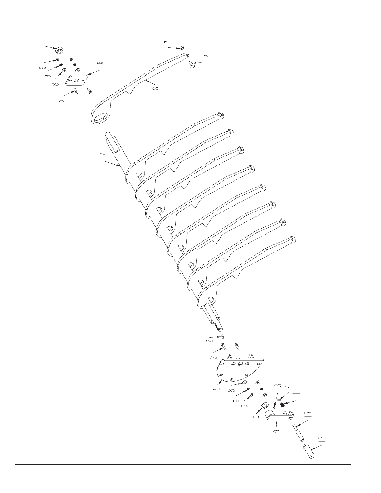
SLUG BAR ASSEMBLY
80
2574 BALEBUSTER PARTS REFERENCE
Page 91

SLUG BAR ASSEMBLY
ITEM PART NO. QTY. DESCRIPTION
1 2000813 1 CLLR\SHFT\1-1/2\SET
2 4800082 4 BOLT\HEX\1/2X1-1/2
3 4800143 2 SCR\SET\ALN\3/8X3/8\NC
4 4800456 1 PIN\RLLD\3/16X1-1/8
5 4800483 9 BOLT\CRG\5/8X2\NC
6 4900001 4 NUT\HEX\1/2\NC
7 4900012 9 NUT\TPLCK\5/8\NC
8 5000004 4 WASH\FLAT\1/2
9 5000006 4 WASH\LOCK\1/2
10 5000008 1 WASH\MACH\1-1/2IDX10GA\NR
11 6100031 1 SPRING\COMP\.072W\25/32OD
12 6200021 1 KEY\SQ\3/8X1-1/2\HARDEND
13 7500736 1 GRIP\HAND\1X4-1/2\FLG
14 8100765 1 SHFT\ADJ\SLUGBAR
15 8101038 1 BRKT\INDEX\SLUGBAR
16 8101039 1 BRKT\BRG\SLUGBAR
17 8101050 1 ROD\HANDLE\INDEX\SLUGBAR
18 8101278 9 BAR\SLUG\ADJ
19 8101306 1 BRKT\MNT\HANDLE\SLUGBAR
2574 BALEBUSTER PARTS REFERENCE
81
Page 92
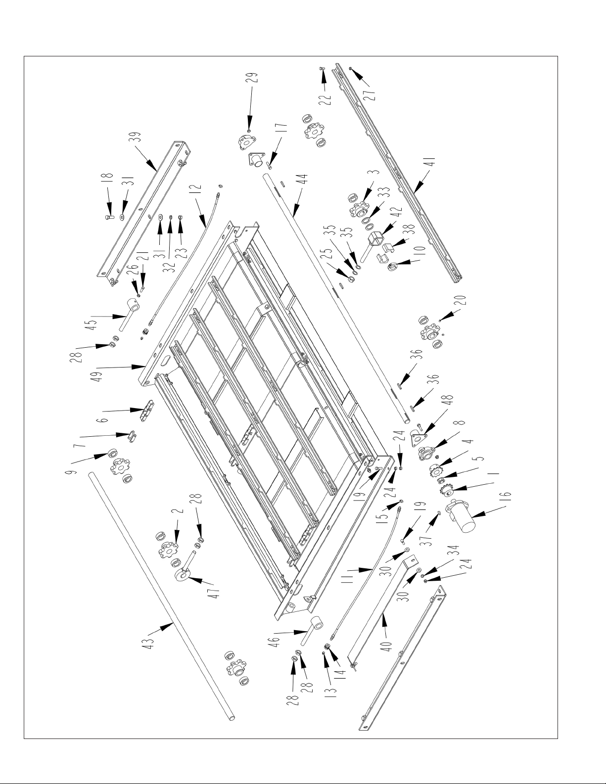
CONVEYOR ASSEMBLY
82
2574 BALEBUSTER PARTS REFERENCE
Page 93

CONVEYOR ASSEMBLY
ITEM PART NO. QTY. DESCRIPTION
1 1000233 1 SPKT\60\B\12\1\1/4KW
2 1000306 3 SPKT\662\7\1-1/4\IDLER
3 1000307 3 SPKT\662\7\1-1/4\1/4KW\DRV
4 1000308 1 SPKT\60\B\12\1-1/4\1/4KW
5 1100240 1 CHAIN\60\12\CPLNG\W-CL
6 1100312 3 CHAIN\620CA\53\W/ATTCH
7 1100319 3 CHAIN\620CA\CL\HITACHI
8 2000333 2 BRG\FLG\CAST\1-1/4\3-BOLT
9 2000805 11 CLLR\SHFT\1-1/2\SET
10 2000827 1 CLLR\SHFT\1-1/4\TWO-PIECE
11 3701601 1 HOSE\LUB\1/8X39\MPS-MPS
12 3701601 1 HOSE\LUB\1/8X39\MPS-MPS
13 3800043 2 FTG\LUB\1/8MPXZRK\SHORT
14 3800895 2 FTG\1/8FP\CPLG\ANCHOR\5/8NF
15 3801009 2 FTG\LUB\1/4-28MX1/8NPTF\45\ELB
16 3900025 1 MOTOR\HYD\17.9\H (NOT INCLUDED IN 8102043)
17 4800034 6 BOLT\HEX\3/8X1-1/2
18 4800082 6 BOLT\HEX\1/2X1-1/2
19 4800098 6 BOLT\HEX\3/8X1-1/4\NC
20 4800227 6 SCR\SET\ALN\5/16X5/16\NC
21 4800307 1 SCR\SET\SQ\3/8X1\NC
22 4800393 54 BOLT\HEX\5/16X7/8\GR8
23 4900001 6 NUT\HEX\1/2\NC
24 4900002 8 NUT\HEX\3/8\NC
25 4900004 1 NUT\HEX\3/4\NC
26 4900026 1 NUT\JAM\3/8\NC
27 4900099 54 NUT\TPLCK\5/16\GR8\NC
28 4900104 6 NUT\JAM\3/4\NC
29 4900109 6 NUT\FLG\TPLCK\3/8\NC
30 5000001 8 WASH\FLAT\3/8
31 5000004 12 WASH\FLAT\1/2
32 5000006 6 WASH\LOCK\1/2
33 5000007 2 WASH\1-1/4\MACH\BUSH
34 5000019 4 WASH\LOCK\3/8
35 5000041 2 WASH\3/4ID\1-1/8OD\16GA
36 6200005 4 KEY\SQ\1/4X1-1/2
37 6200011 1 KEY\WDF\1/4X1
38 7501589 2 BRG\NYLTRN\1-1/4\HALF\2SQ-OD
39 8101048 2 MNT\CNVYR\3\BRK
40 8101052 2 PL\RUB\CHAIN\CNVYR
41 8101053 9 PLT\SLAT
42 8101852 1 MNT\BRG\SPLIT\CNVYR
43 8102030 1 SHFT\IDLER\1-1/4\CNVYR
44 8102031 1 SHFT\DRIVE\1-1/4\CNVYR
45 8102032 1 BRKT\SHAFT\IDLER\CNVYR
46 8102033 1 BRKT\SHAFT\IDLER\NO-TAP\1-1/4
47 8102034 1 SUP\SHFT\IDLER\CNVYR\1-1/4
48 8102035 2 GUARD\TWINE\CNVYR\3HL
49 8102038 1 FRM\CNVYR\FLATBOTTOM\1-1/4”
8102043 CNVYR\ASSY\1-1/4\SHFT\LH\COMPLETE
2574 BALEBUSTER PARTS REFERENCE
83
Page 94
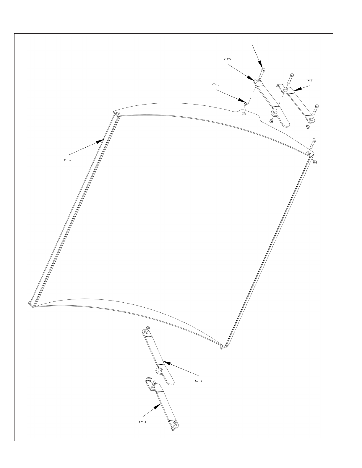
RACK ASSEMBLY
84
2574 BALEBUSTER PARTS REFERENCE
Page 95

RACK ASSEMBLY
ITEM PART NO. QTY. DESCRIPTION
1 4800351 8 BOLT\HEX\1/2X2-3/4
2 4900014 8 NUT\TPLCK\1/2\NC
3 8101090 1 BRKT\STRAP\RACK\W-STOP\FRONT
4 8101091 1 BRKT\STRAP\RACK\W-STOP\REAR
5 8101092 1 BRKT\STRAP\RACK\FRONT
6 8101093 1 BRKT\STRAP\RACK\REAR
7 8102028 1 RACK\2574
2574 BALEBUSTER PARTS REFERENCE
85
Page 96
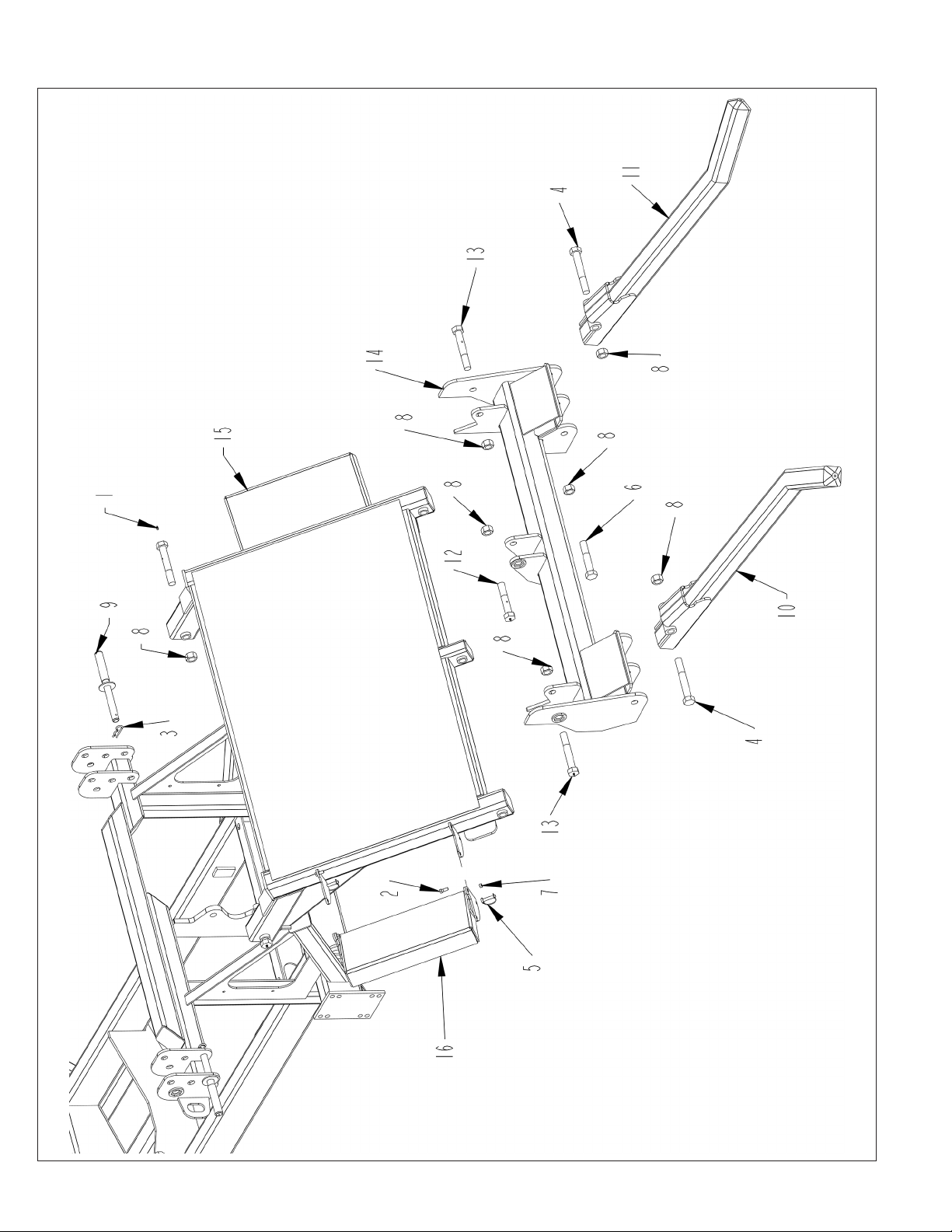
LOADER ASSEMBLY
86
2574 BALEBUSTER PARTS REFERENCE
Page 97

LOADER ASSEMBLY
ITEM PART NO. QTY. DESCRIPTION
1 3800082 5 FTG\LUB\1/4NFXZERK\ADAPT
2 4800003 2 BOLT\HEX\3/8X1
3 4800056 2 PIN\HAIR\3/16(#3)
4 4800471 2 BOLT\HEX\1X7\NC
5 4800609 2 PIN\LYNCH\3/8X1-3/4\W/_U_WIRE;KEEPER
6 4800633 1 BOLT\HEX\1X5-1/2\NC\GR5\PLT
7 4900023 2 NUT\TPLCK\3/8\NC
8 4900127 8 NUT\TPLCK\1\NC
9 8100794 2 PIN\LOCK\TRANSPORT
10 8101033 1 TINE\SQ\LEFTHAND
11 8101075 1 TINE\SQ\RIGHTHAND
12 8101311 1 BOLT\HEX\1X5-1/2\GREASE
13 8101312 4 BOLT\HEX\1X6-1/2\GREASE
14 8101513 1 LOWER\LOADER
15 8101992 1 LOADER\UPPER\
16 8101993 1 WING\FOLDING
8102011 LDR\ASSY\2574
2574 BALEBUSTER PARTS REFERENCE
87
Page 98
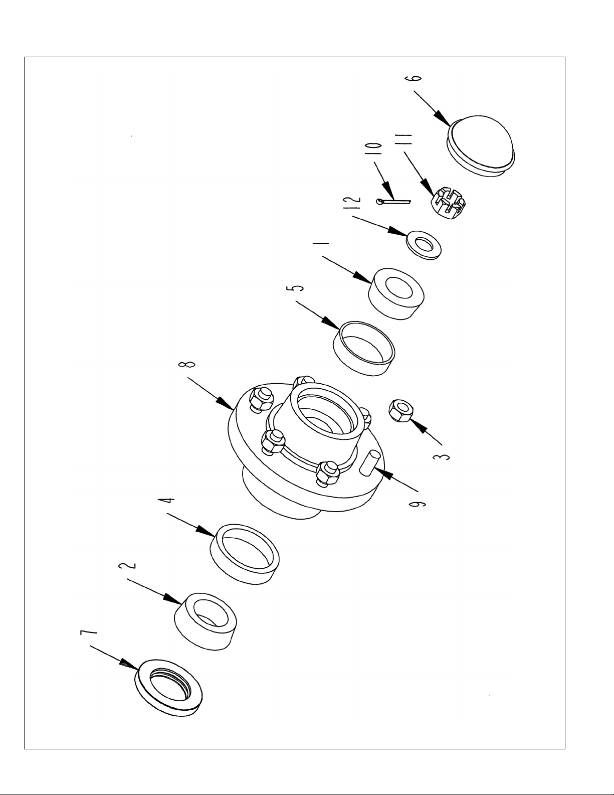
WHEEL AND BEARING ASSEMBLY
88
2574 BALEBUSTER PARTS REFERENCE
Page 99

WHEEL AND BEARING ASSEMBLY
ITEM PART NO. QTY. DESCRIPTION
1 2900024 1 CONE\BRG\OUTER\25877
2 2900029 1 CONE INNER/WHEL HUB\25590
3 2900083 6 NUT\TAPER\WHEEL\1/2\NF\
4 2900164 1 BRG\CUP\INNER\875\25520
5 2900165 1 BRG\CUP\OUTER\875\25821
6 2900168 1 CAP\DUST\875
7 2900169 1 SEAL\GREASE\875\P602110
8 2900171 1 HUB\6-BOLT\STUDS\COMPLETE (INCLUDES ITEMS 1, 2, 3, 4, 5, 6, 7, 9)
9 2900172 6 STUD\WHL\9/16-18X2-1/8\GR5\P151403
10 4800044 1 PIN\COT\5/32X1-1/2
11 4900054 1 NUT\CASTLE\1/2\NF
12 5000055 1 WASH\SPINDLE\7/8
2574 BALEBUSTER PARTS REFERENCE
89
Page 100
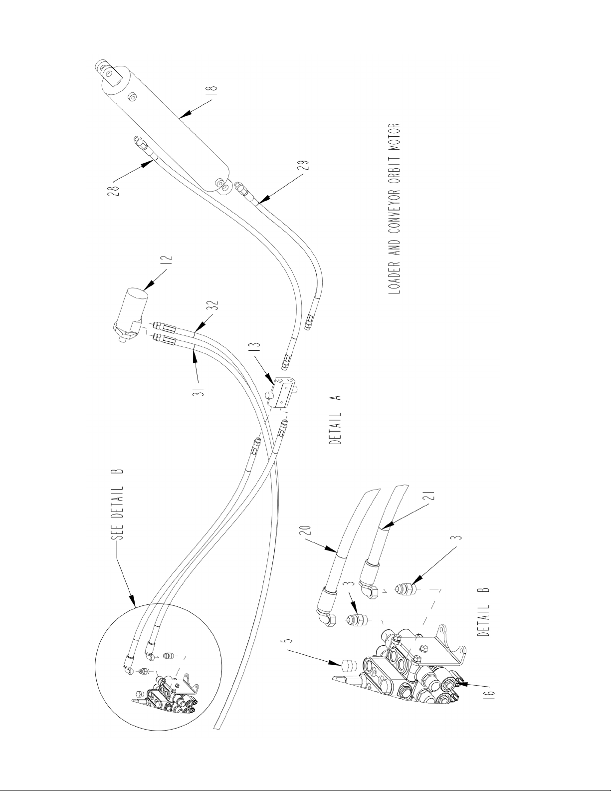
HYDRAULIC ASSEMBLY - DETAILS A AND B (THRU S.N. 0051)
90
2574 BALEBUSTER PARTS REFERENCE
 Loading...