

Page 1
1
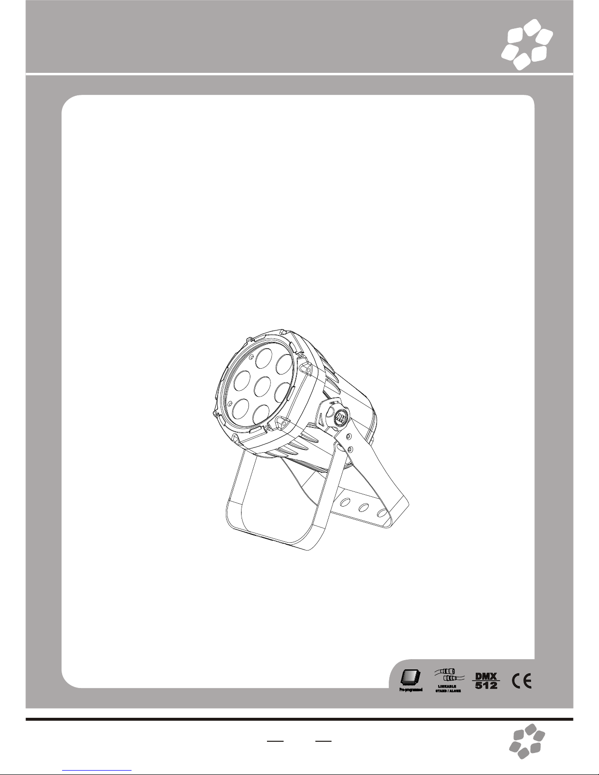
LED SPOT LIGHT 4 in 1)
USER MANUAL
Page 2

2
CONTENTS
1.BEFORE YOU BEGIN.......................................................3
What is included...............................................................3
Unpacking Instructions......................................................3
AC POWER......................................................3
Safety Instructions............................................................4
2.INTRODUCTION............................................................5
Specifications..................................................................5
Features.............................................................................5
Product overview...............................................................6
Dimensions.............................................................................6
3.SETUP................................................................................7
Installation Requirement......................................................7
Connection of DMX Signal Wire.............................................8
3-PIN TO 5-PIN CONVERSION CHART............................8
4.OPERATIG INSTRUCTIONS...............................................9
Control Panel Functions.......................................................9
Menu Map............................................................................10
Operating instructions............................................................11
DMX512 Controller Mode......................................................12
DMX512 Channel Values......................................................12
ID Address Instructions.....................................................16
Master/Slave Control Mode................................................17
5. APPENDIX................................................18
Service Maintenance Guide................................................18
Blow-out Diagram................................................20
Page 3
3
1.BEFORE YOU BEGIN
What is included
Ø 1 x Fixture
Ø 1 x Power cable with plug
Ø 1 x User Manua
Unpacking Instructions
Immediately upon receiving a fixture, carefully unpack the carton; check the
contents to ensure that all parts are present, and have been received in good
condition. Notify the shipper immediately and retain packing material for
inspection if any parts appear damaged from shipping or the carton itself shows
signs of mishandling. Save the carton and all packing materials. In the event that
a fixture must be returned to the factory, it is important that the fixture be returned
in the original factory box and packing.
AC POWER
This fixture has an auto-switching switch-mode power supply that can
accommodate a wide range of input voltages. The only thing necessary to do
before powering on the unit is to make sure the line voltage you are applying is
within the range of accepted voltages. This fixture will accommodate between
100V and 240V AC 50-60 Hz.
Help preserve the environment! Ensure that this product is
recycled at the end of its life. Your supplier can give details
of local arrangements for the disposal of products.
Page 4
4
Safety Instructions
!
WARNING!
Please read these instructions carefully, which includes
important information about the installation, usage and
maintenance of this product..
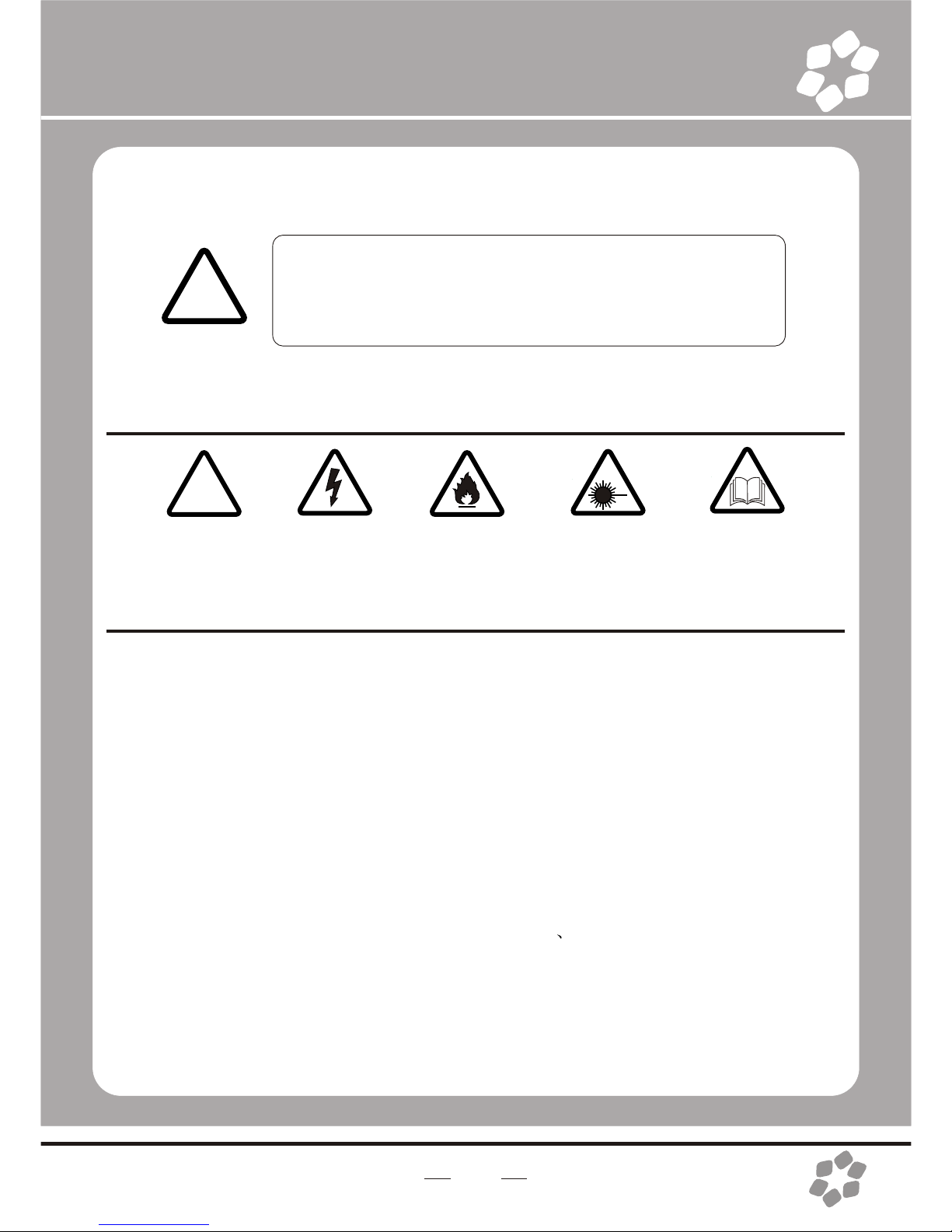
The following symbols are used to identify important safety information on the
product and in this manual:
!!
DANGER!
Safety hazard.
Risk of severe
injury or death
DANGER!
Hazardous
Voltage. Risk of
lethal or severe
electric shock.
WARNING!
Fire hazard
WARNING!
LED light
emission. Risk
of eye injury.
WARNING!
Refer to user
= This light belongs to grade I protection device, therefore the light must connect
to the earth excellently. And the power connection must be operated by the
professional technician.
= Make sure that the working voltage will not higher or lower than the rated value.
= Make sure that the cable didn't be damage or lacerated by sharp.
= The light must be power off when it's standing idle or before clearing.
= The cable must with plug, and you must pull out the cable by handle the plug.
= Please be careful when installing the lighting. Never touch the bared cable, or
it will cause the deadly electric shock.
= Please use the suitable and safe cable to connect the light.
= Please never remodel the light randomly, we will not take the guarantee for the
faulty and damage which caused by dismantle repair or remodel of the
nonprofessional person.
= Maximum ambient temperature 40°C. Do not operate fixture at temperatures
higher than this.
= Never connect the device to a dimmer pack.
Page 5

5
2.INTRODUCTION
Specifications
l Voltage Rating: AC100V 240V 50-60Hz
l Power Rating: 60W
l LED Quantity: 7 pcs 4 in 1LEDs(RGBW)
l LED: 500mA
l Beam Angle: 20°/30°/40°(option)
l Ingress Protection: IP65/IP20
l Product Size: 190X148X238mm
l Package Size:230X200X295 mm
l N/W:2.5Kgs
Features
l RGBW color mixing with or without DMX controller
l 5 distinct dimming curves
l User defined program/ inner optional program
l LED display with password protection
l Transfer custom programs between fixtures
l Operating Modes: DMX512 Connection with ID Address/Master & Slave...
l DMX Channels: STAG/col.d
11 channels(STAG): Dimmer+RGBW+ Macro + strobe + AUTO + auto speed
+ dimming speed +ID
5 channels(col.d):Dimmer+RGBW
Page 6
6
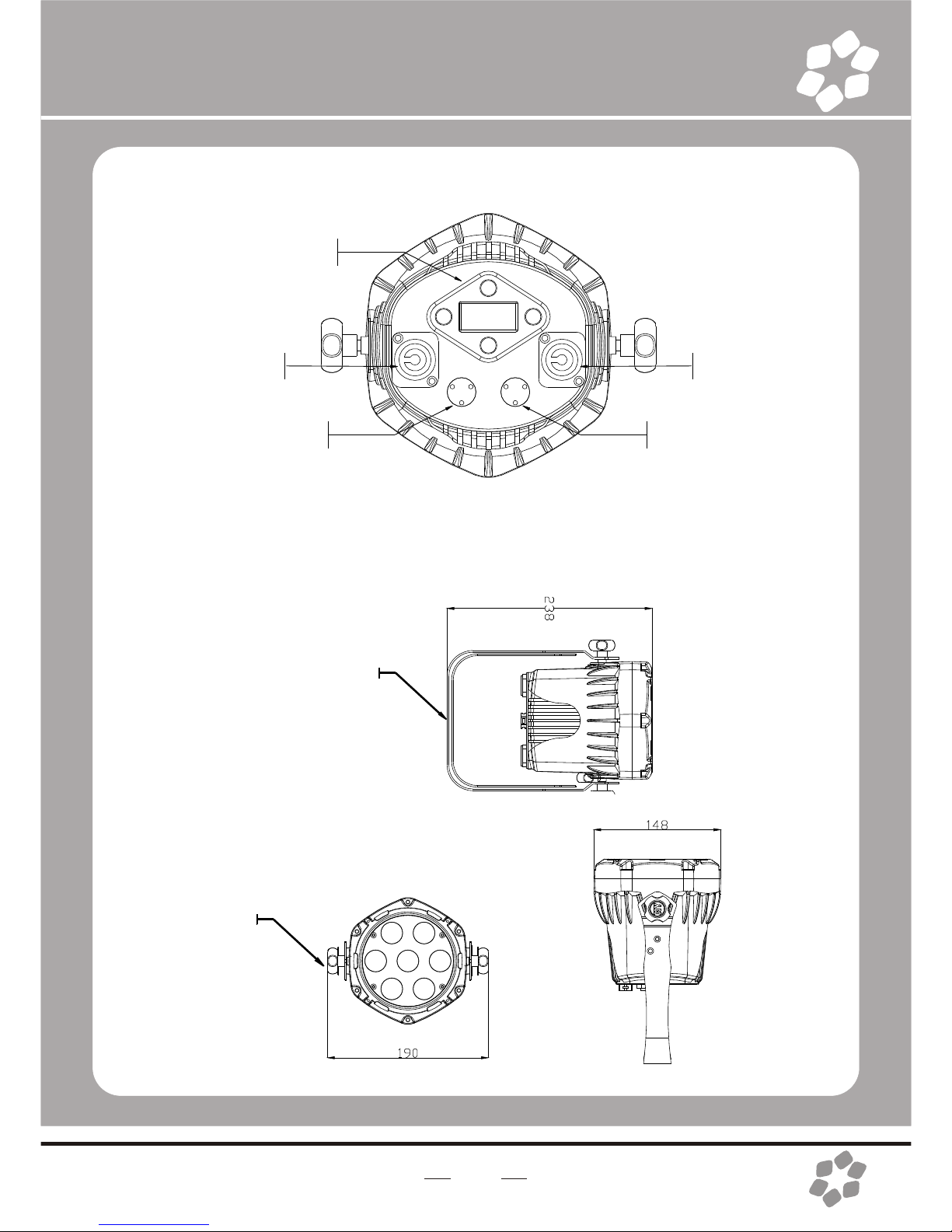
Product Overview
Dimensions
Control board
DMX IN
DMX OUT
Hanging
bracket/ floor
stand
Bracket
adjustment
knob
POWER OUT
POWER IN
Page 7
7
3.SETUP
Installation Requirement
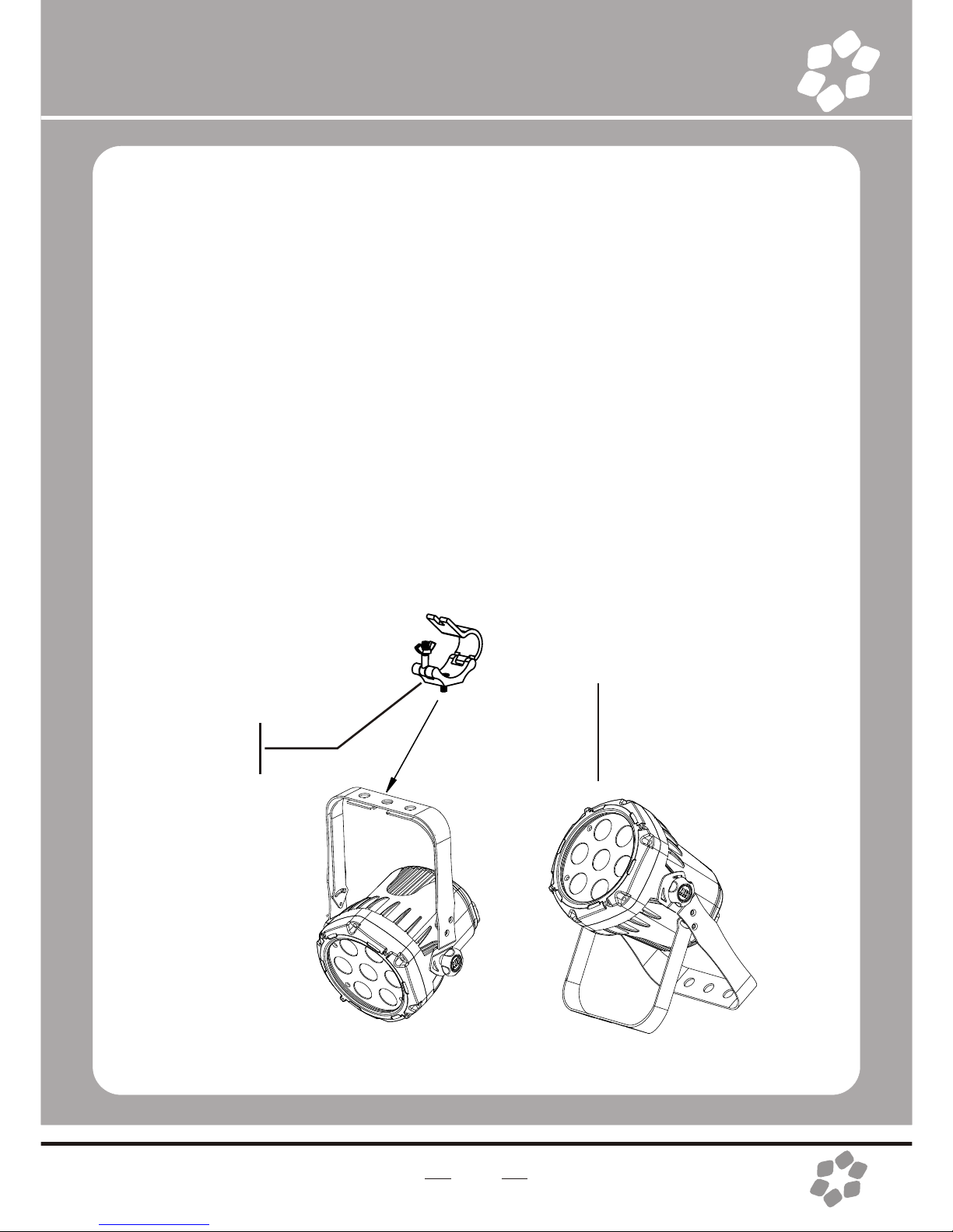
l This product can be used in a variety of situations, can hang and put on
the ground.
l If hanging the fixture for over head use, then please follow the below steps.
l Please choose the suitable location to put or hang the light when installing it.
You must use the exclusive clamp hanger and screw when hanging it, and
make sure the weight of the light is within limits of the hanger.
l Please make sure without any flammable objects within 0.5m when
installing the light.
l The installation should be operated by professional person; any irregular
installation will cause the body injury or equipment damage.
l Block access below the work area and use suitable and stable platform
when installing or servicing fixture.
Hanging Clamp
Note: sold
separately
Safety Cable
Note: the cable must be
secured through the heat
sink ventilation
passageway.
Page 8
8
Connection of DMX Signal Wire
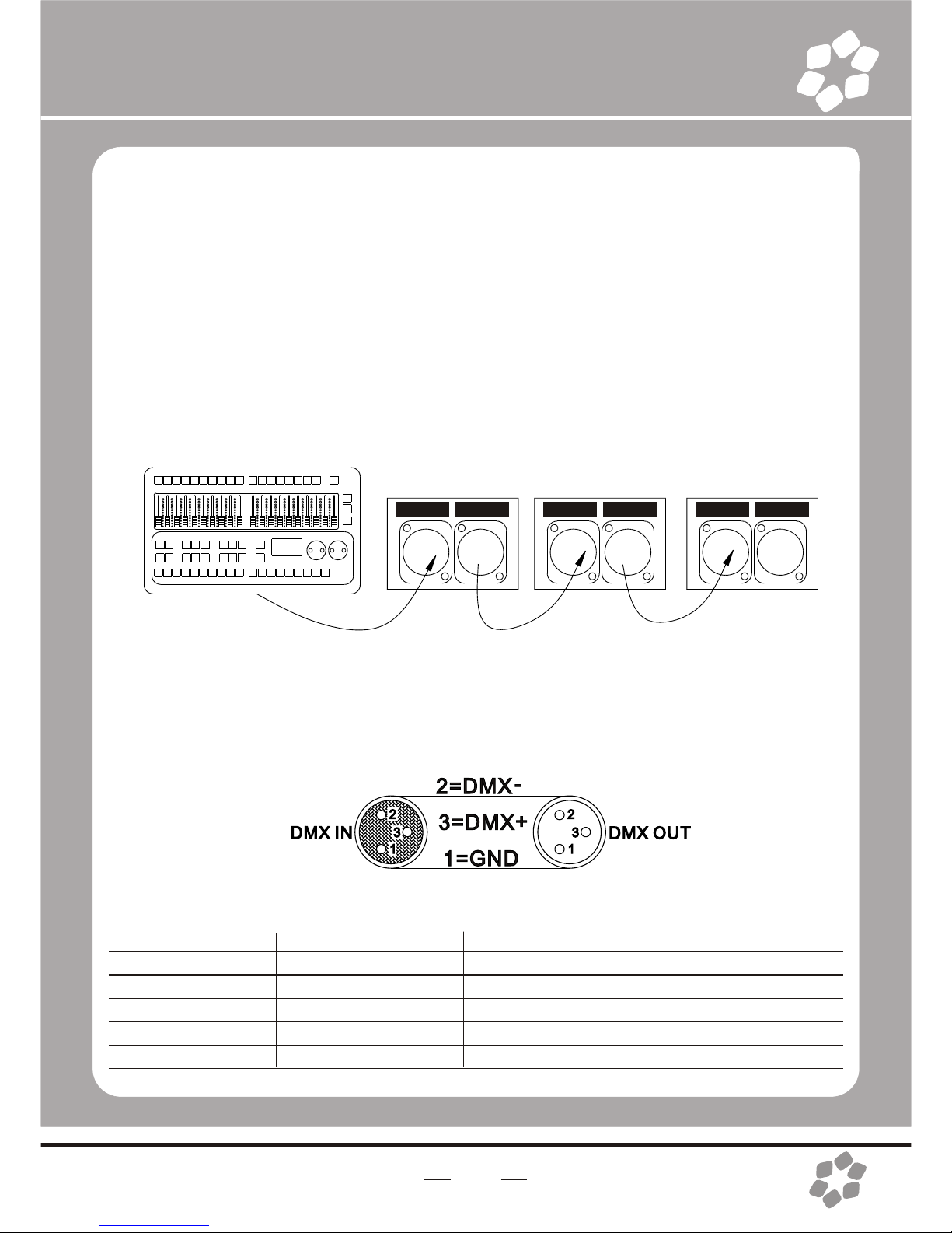
1 Please use the fixture controller wire specially when use the DMX512
Controller. Connect the (male) 3 pin connector side of the DMX cable to
the output (female) 3 pin connector of the first fixture.
2 Connect the end of the cable coming from the first fixture which will have
a (male) 3 pin connector to the input connector of the next fixture
consisting of a (female) 3 pin connector. Then, proceed to connect from
the output as stated above to the input of the following fixture and so on.
3 This product can be connected numerous lamps in series without the
need for the signal amplifier; the signal will not be weakened.
DMX IN DMXOUT DMX IN DMXOUT DMX IN DMXOUT
3-PIN TO 5-PIN CONVERSION CHART
Note! If you use a controller with a 5 pin DMX output connector, you will
need to use a 5 pin to 3 pin adapter.
Conductor
Ground/Shield
Data ( - ) signal
Data ( + ) signal
Do not use
Do not use
3 Pin Female(output)
Pin 1
Pin2
Pin 3
5 Pin Male (Input)
Pin 1
Pin2
Pin 3
Do not use
Do not use
3 PIN TO 5 PIN CONVERSION CHART
Page 9
9
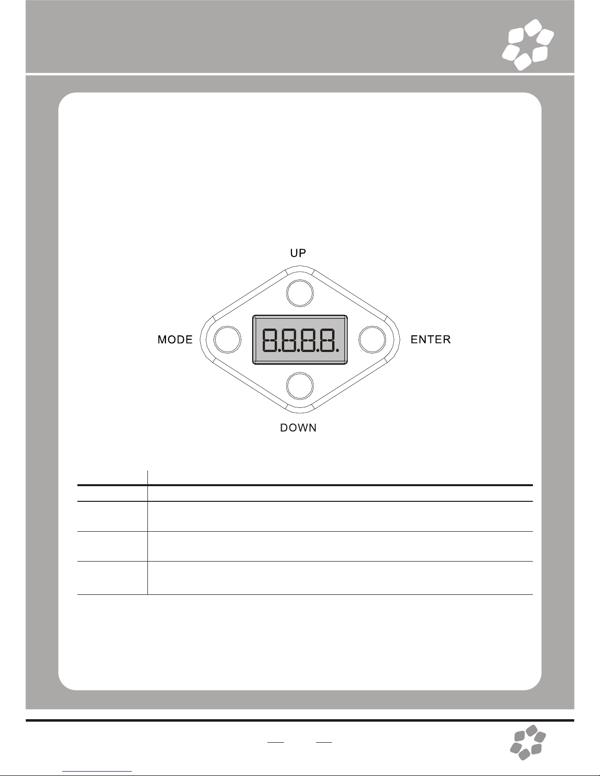
BUTTON
MODE
ENTER
UP
DOWN
FUNCTION
Exits from the current menu or function
Enables the currently displayed menu or sets the currently selected
value in to the selected function
Navigates upwards through the menu list and increases the numeric
value when in a function
Navigates downwards through the menu list and decreases the numeric
value when in a function
4.OPERATING INSTRUCTIONS
Control Panel Functions
Page 10
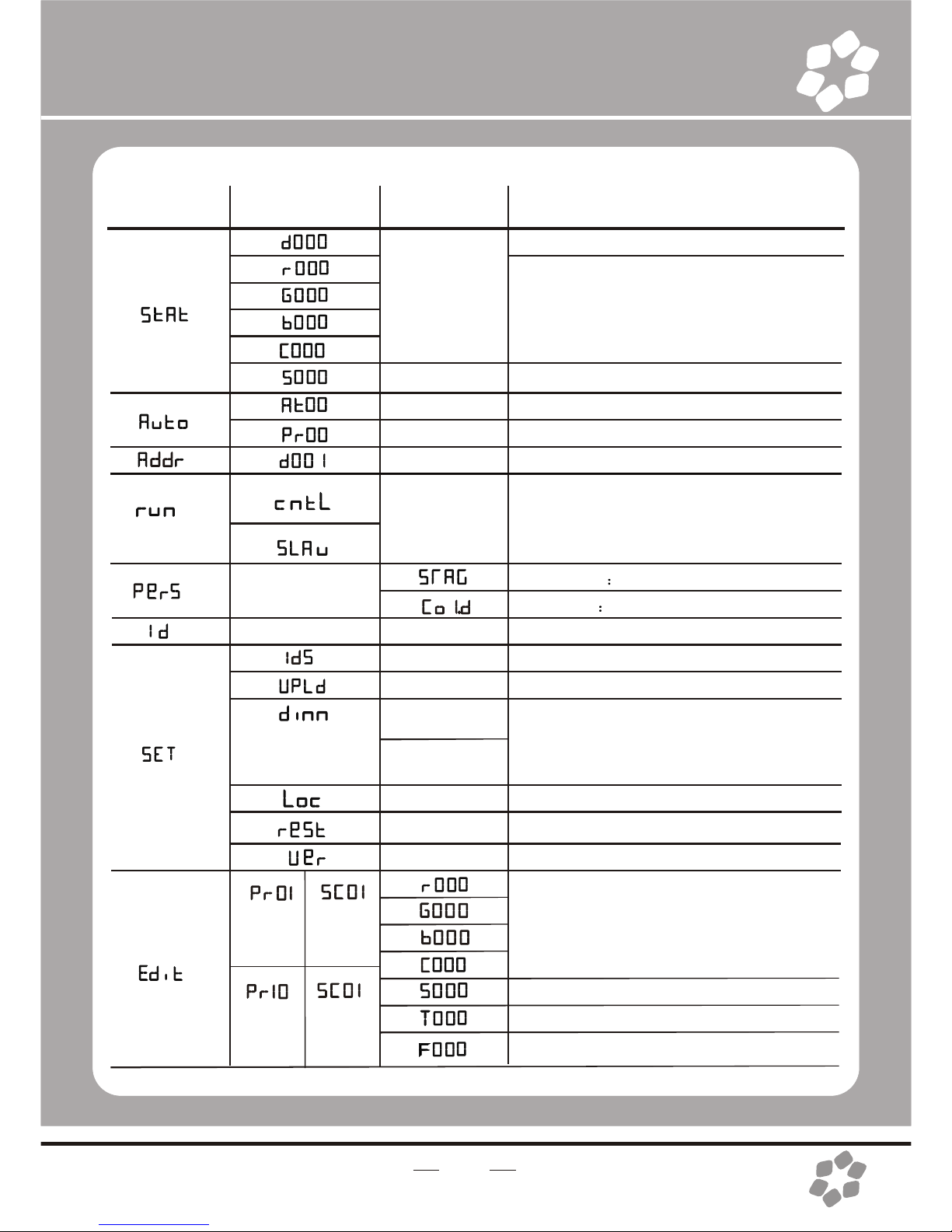
MAIN
FUNCTION
SUB-
FUNCTION SELECTION
000~255
(0 ~ 100%)
00~20
01~10
01~10
001~512
ON~OFF
Password
OFF
DIM1/2/3/4
ON~OFF
Password
V1.38
01~66
01~09
custom
custom
01~30
scene
01~90
scene
INSTRUCTION
Dimmer
User can combine RED, GREEN,BLUE
and WHITE to generate a custom color
Select strobe frequency
10 auto programs available
chose program from 10 “EDIT” programs
Set DMX start addressSets the
operating mode for the fixture:to
receive signal from a DMX controller
(cntl) .receive signal or Download
programs from Master fixture. (Slave)
11 channels D+RGBW +S…
5 channels D + RGBW
Assign ID address for fixtures
Enable or disable ID
Upload programs(Password required)
"Off" means select linear dimming, or
choose dimmer 1-4 to control the dimming
speed, dimming 1 of the fastest dimming
curves, 4 for the most slowly dimming curve
Enables or Disables password lockout
Reset factory defaults
Version number
User can combine RED, GREEN,BLUE
and WHITE to generate a custom
color(0~255)
(0~20Hz)Select strobe frequency
(0~255) step time
transition time of last step to current step
10
Page 11
11
Operating instructions
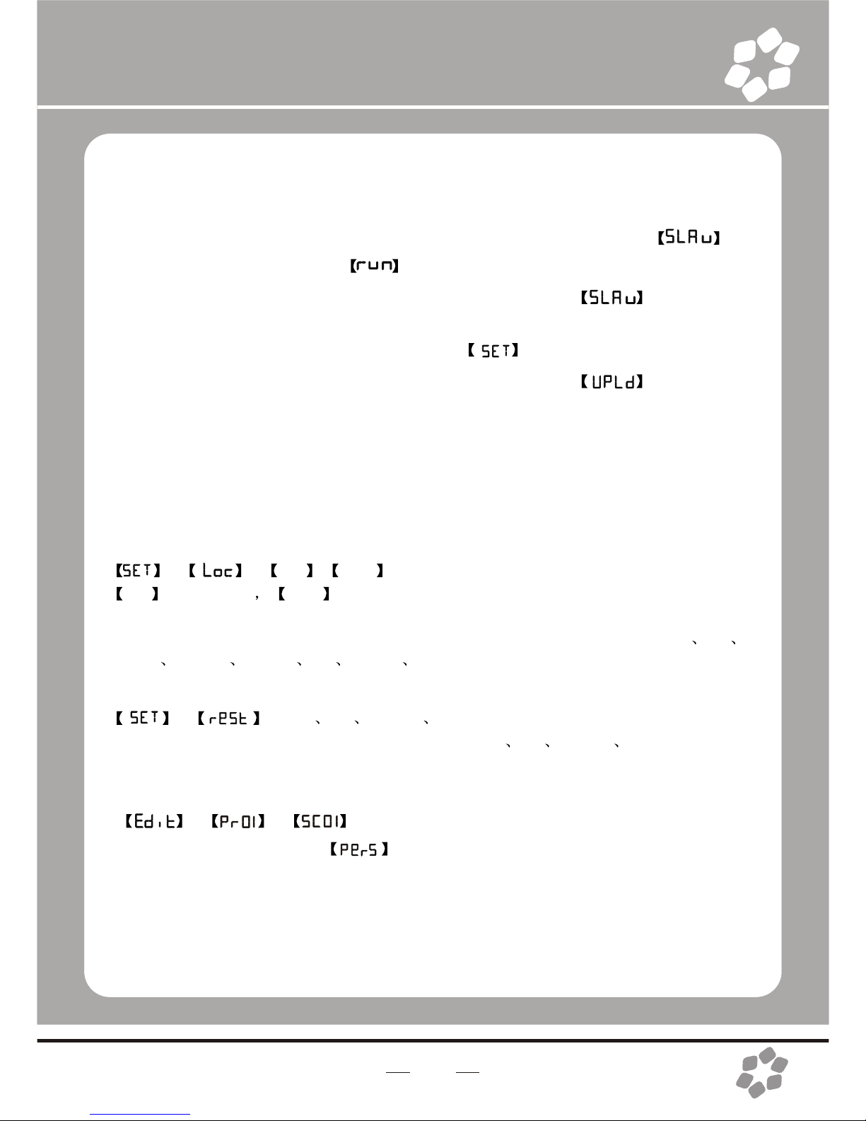
1.Upload custom program or set to another machine
Set all the fixtures which receive custom programs from the source fixture as
1 Press MODE button until is displayed.
2 Then press ENTER button, use UP/DOWN buttons until is displayed.
Press MODE return to MENU
3 On the Master unit, Press MODE button until is displayed on source fixture.
4 Then press ENTER button, use UP/DOWN buttons until is displayed.
5 Then press ENTER button, Input password UP, UP, DOWN, DOWN, press
ENTER.All the lights display yellow color when uploading.After upload finish,it
will turns to green which means upload successful.If has mistake,it will turns
to red color.
6 Press <MODE> on the source unit to exit the upload mode.
2 Enable password lock
Ü Ü ON / OFF Ü {ENTER}
ON enable lock OFF disable lock
Enable the password lock, control panel in the boot or go into standby automatically
take effect, this time to operate lamps need to enter your password. { MODE UP
MODE DOWN MODE UP MODE DOWN }Ü {ENTER}
3 Factory reset
Ü Ü {UP UP DOWN DOWN}Ü {ENTER}
Note: The password is permanently set as {UP UP DOWN DOWN}
Then press ENTER button
4 Custom program
Ü Ü
1 Press MODE button until is displayed, press ENTER access program mode.
2 Select the program you'll edit by pressing UP/DOWN buttons. The available
range is o1-10.
3 Select the step you'll edit by pressing UP/DOWN buttons, and then press
ENTER button access program.
Page 12
12
When 'R000' display on the screen, press the UP/DOWN button to choose the value.
Repeat this step to edit the value of 'G000', 'b000', 'C000', 'S000', 'T000' and 'F000'.
Please pay attention for the 'S' is the rate of strobe. 'T' is the operating time of the
present step, the value is between 0 to 255. 'F' is the transitional time from previous
step to present step. The transitional time is the quickest when the FADE is 0.
Notice: Please operate the program in turn, from the 01st step to the 30th step.
When the operating program less than 30 steps, please set the final step value be 0
4 Repeat step 3 till complete programming.
5 Exit program mode by pressing MODE buttons three times.
DMX512 Controller Mode
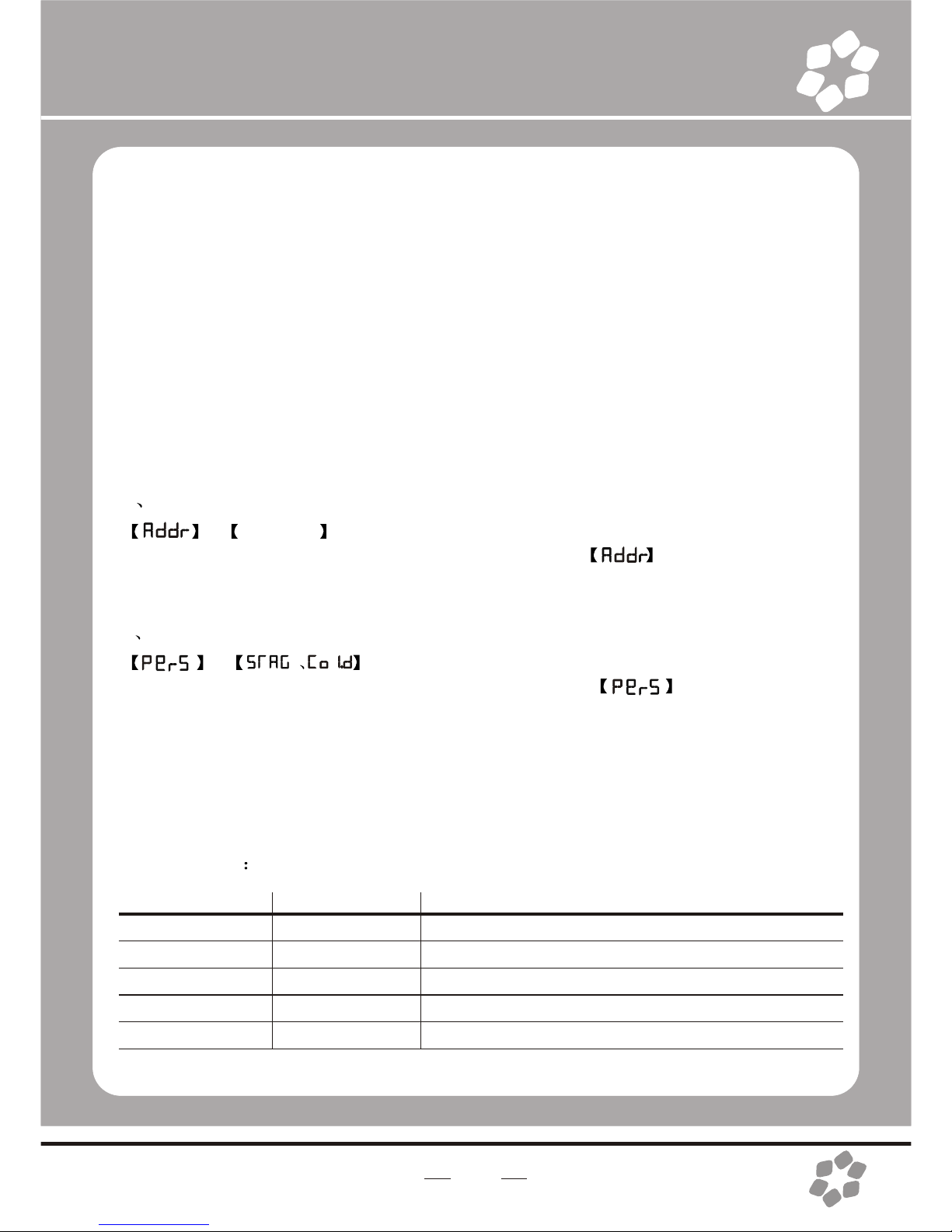
1 Setting DMX512 Address
Ü 001--512
Access control panel function by pressing MODE until is displayed.
Press ENTER, add or reduce channels by pressing UP/DOWN between 001 and 512.
Press MODE to exit.
2 Setting Channels
Ü
Access control panel function by prekssing MODE until is displayed.
Press ENTER button, select DMX channel by pressing UP/DOWN,
Press MODE to exit.
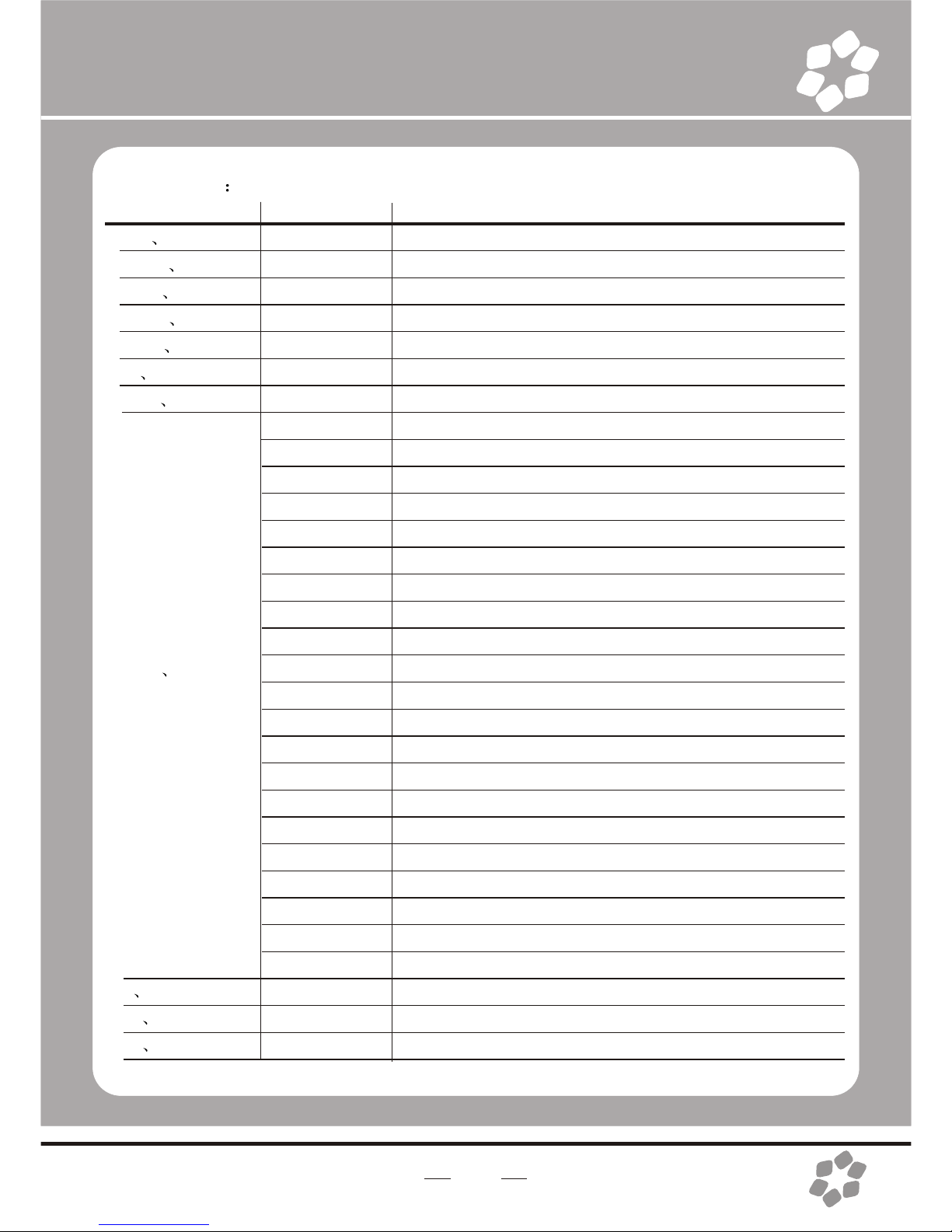
DMX512 Channel Values
5 channels Cold
Channel
1
2
3
4
5
Value
000~255
000~255
000~255
000~255
000~255
Description
Dimmer
Red
Green
Blue
White
Page 13
13
Channel
1 Dimming
2 RED
3 Green
4 Blue
5 White
6 Macro color
7 Strobe
8 auto &
custom program
9 Auto Speed
10 Dimming speed
11 ID
Value
000~255
000~255
000~255
000~255
000~255
000~255
000~255
000~009
010~019
020~029
030~039
040~049
050~059
060~069
070~079
080~089
090~099
100~109
110~119
120~129
130~139
140~149
150~159
160~169
170~179
180~189
190~199
200~225
000~255
000~255
000~255
Description
0-100%
0-100%(Or STEP TIME when CUS.01-10 is activated)
0-10 0%(Or FADE TIME when CUS.01-10 is activated)
0-100%
0-100%
Macro color control
(00~20Hz)
No Function
Out1 AUTO1
Out2 AUTO2
Out3 AUTO3
Out4 AUTO4
Out5 AUTO5
Out6 AUTO6
Out7 AUTO7
Out8 AUTO8
Out9 AUTO9
Out10 AUTO10
cust1 custom program 1
Cust2 custom program 2
Cust3 custom program 3
Cust4 custom program 4
Cust5 custom program 5
Cust6 custom program 6
Cust7 custom program 7
Cust8 custom program 8
Cust9 custom program9
Cust10 custom program10
0~100%(only when using ch.8)
Dimming speed
ID address selection
11 channels STAG
Page 14
14
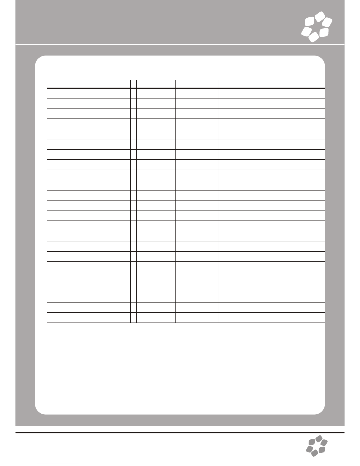
ID ADDRESS SELECTION
VALUE
000~009
010~019
020~029
030~039
040~049
050~059
060~069
070~079
080~089
090~099
100~109
110~119
120~129
130~139
140~149
150~159
160~169
170~179
180~189
190~199
200~209
210
211
FUNCTION
All Ids
ID1
ID2
ID3
ID4
ID5
ID6
ID7
ID8
ID9
ID10
ID11
ID12
ID13
ID14
ID15
ID16
ID17
ID18
ID19
ID20
ID21
ID22
VALUE
212
213
214
215
216
217
218
219
220
221
222
223
224
225
226
227
228
229
230
231
232
233
234
FUNCTION
ID23
ID24
ID25
ID26
ID27
ID28
ID29
ID30
ID31
ID32
ID33
ID34
ID35
ID36
ID37
ID38
ID39
ID40
ID41
ID42
ID43
ID44
Id45
VALUE
235
236
237
238
239
240
241
242
243
244
245
246
247
248
249
250
251
252
253
254
255
FUNCTION
ID46
ID47
ID48
ID49
ID50
ID51
ID52
ID53
ID54
ID55
ID56
ID57
ID58
ID59
ID60
ID61
ID62
ID63
ID64
ID65
ID66
MASTER DIMMER
Channels 1 controls the intensity of the currently projected color
When the slider is at the highest position (255), then the intensity of the output is at
themaximum.
RED, GREEN,BLUE AND WHITE COLOR SELECTION
Channels 2, 3,4 and 5 control the intensity ratio of each of the Red, Green, Blue& White LEDs.
1,2,3,4 and 5 channel can be used in combination
Page 15

15
COLOR MACROS
Channel 6 selects the required Color Macro.
Channel 6 has priority over Channels 2, 3,4 & 5 .
Channel 1 is used to control the intensity of the current Color Macro.
STROBE
Channel 7 controls the strobe of Channels 1 through 6.
Channel 7 has priority over Channels 2, 3, 4,5 & 6.
Speed of the strobe is adjustable from 0 to 20 Hz.
AUTO & CUSTOM PROGRAMS
Chanel 8 selects the preset Auto/Custom programs 1~10
When activating the Auto/Custom programs, it is then possible to control the Step time
and Fade time by using Channels 2 & 3 respectively.
Channel 8 has priority over channels 2-7.
DIMMER SPEED
Channel 10is for selecting the dimmer mode and dimmer speed.
When channel 9 is not activated, then RGBW and Master Dimmer are linear.
The dimmer modes 1, 2, 3, and 4 are different speeds of the nonlinear dimming curves
ID ADDRESS SELECTION
Use channel 11 to select ID addressed fixtures.
Each independent DMX address can have up to 66 ID addressed fixtures.
ID address “0” allows control of all fixtures simultaneously.
Page 16
16
ID Address Instructions
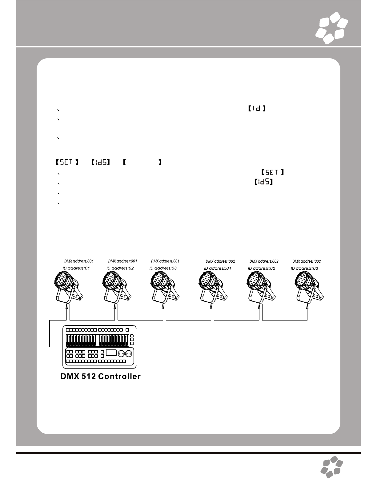
1.Setting ID address
1 Access control panel function by pressing MODE until is displayed.
2 Press ENTER, increase or reduce ID values by pressing UP/DOWN between 01
and 66.
3 Press MODE to exit.
2. Enable or disable ID
Ü Ü ON-OFF
1 Access control panel function by pressing MODE until is displayed.
2 Press ENTER, select by pressing UP/DOWN until is displayed.
3 Press ENTER, turn on or off ID addressing by pressing UP/DOWN buttons.
4 Press MODE to exit.
For every DMX512 address the user can set 66 separate ID addresses. ID
addressing is a secondary function in DMX512 mode. In DMX512 Controller Mode,
the user can simultaneously control the individual DMX address of all lights, and
can control the lights which have separate ID address in independent DMX512.
Select STAG channel on fixture's control panel (Please refer to DMX512
Channels Selection). The figure above shows a simple DMX layout which has
used three units at each DMX address. The three units have different ID
addresses. In the DMX address: 001, the user can control the first three lights
Page 17
17
simultaneously. When using channel 11 select the channel number is 020-029
and ID Address=02, the controller can control the second light individually.
When using channel 11 select the channel number is 000-010 and ID
Address=00, all the lights are in common use at the same DMX address.
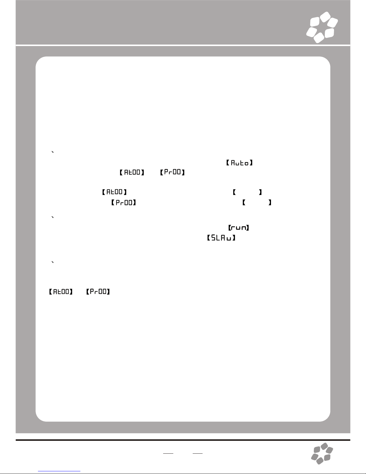
Master/Slave Control Mode
1 Setting master machine
Access control panel function by pressing MODE until is displayed.
Press ENTER, select or by pressing UP/DOWN buttons.
Press ENTER, and then press MODE to exit.
You can choose pre-set programs, the range is o1--10 .
Or you can choose custom programs, the range is o1--10 .
2 Setting slave machine
Access control panel function by pressing MODE until is displayed.
Press ENTER, press UP/DOWN buttons until the is displayed.
Press MODE return to MENU
3 Usage of Master/Slave
When two or more fixtures connected, you can set up the first machine as the
Master and the followed fixtures as Slaves. The Master can choose pre-set programs ...
or , all the slaves will follow the Master's operation synchronously.
Page 18
18
Breaker/Fuse keeps
blowing
Device has no power
Fixture is not
responding to DMX
Loss of signal
Check total load placed on the electrical circuit
Check for a short in the electrical wiring: internal and/or external
Check for power on Mains
-Note: In the event of autoswitching transformer failure, the unit
can be sent in for repair; however, a replacement part can be
ordered directly from Our company
Check Control Panel settings for correct addressing
Check DMX cables
Check polarity switch settings on the controller
Check cable connections
Call service technician
-Note: In the event of Display PCB failure, a replacement PCB
can be ordered directly from Our company
Use only DMX cables
Install terminator
Note: Keep DMX cables separated from power cables or black
lights
5. APPENDIX
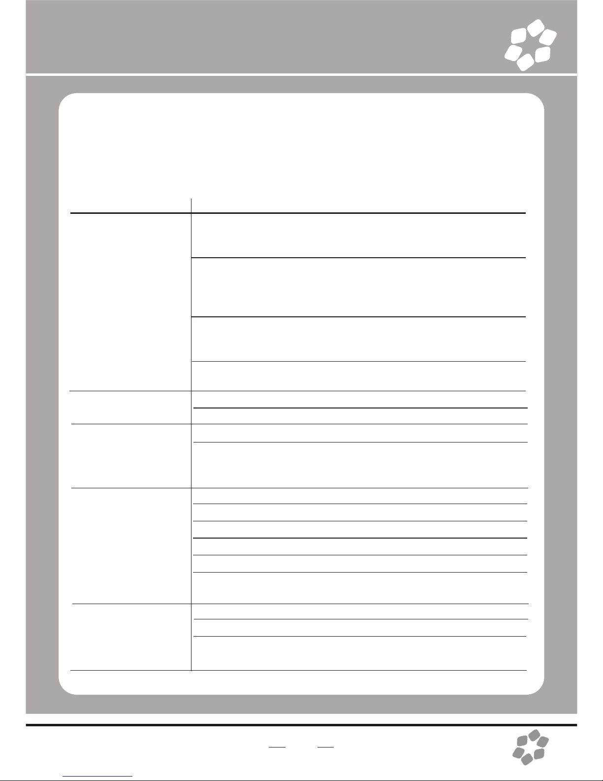
Service Maintenance Guide
Symptom(s)
1 or more LED's are
not illuminating
Possible Solution(s)
Clean the fixture regularly to avoid any such failure. This fixture is
convection cooled, which means that if the surface is kept clean
and free of debris, then proper cooling will be allowed to occur
An LED may have failed, resulting in an open circuit. In this event,
all of the red, green, or blue in a single module will no longer
illuminate. This does not mean that all of the LEDs have failed,
but the circuit is wired in series.
An LED may have failed, resulting in a short circuit. In this event, only
the single LED which has failed will no longer function. This does not
mean that all of the LEDs have failed, but the circuit is wired in series.
-Note: In the event of LED failure, a replacement LED PCB
assembly may be purchased directly from Our company
Page 19
19
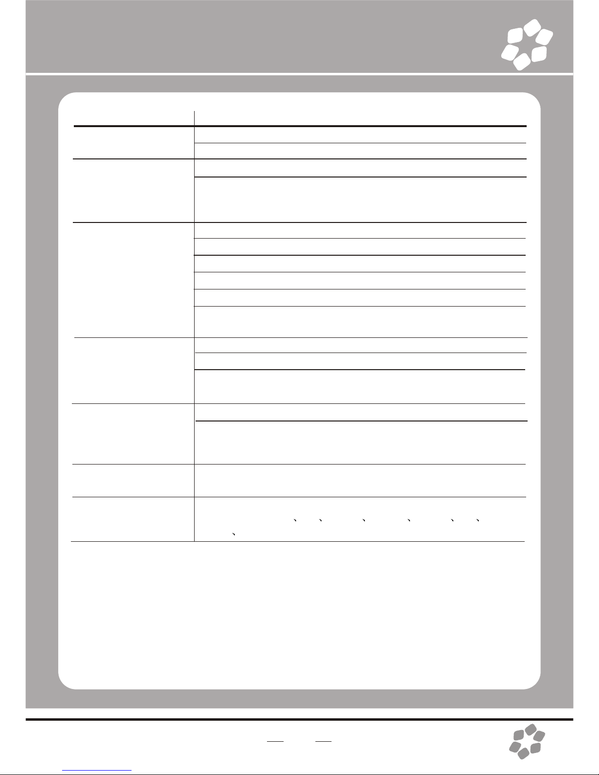
Symptom(s)
Breaker/Fuse keeps
blowing
Device has no power
Fixture is not
responding to DMX
Loss of signal
COLOR-CON
Controller does not
function, or does not
function properly
Stand alone
operation
The display is only
showing: ####
Possible Solution(s)
Check total load placed on the electrical circuit
Check for a short in the electrical wiring: internal and/or external
Check for power on Mains
-Note: In the event of autoswitching transformer failure, the unit
can be sent in for repair; however, a replacement part can be
ordered directly from Our company
Check Control Panel settings for correct addressing
Check DMX cables
Check polarity switch settings on the controller
Check cable connections
Call service technician
-Note: In the event of Display PCB failure, a replacement PCB
can be ordered directly from Our company
Use only DMX cables
Install terminator
Note: Keep DMX cables separated from power cables or black
lights
Make sure connector is firmly connected to device
This fixture must be in the correct mode in order to properly
respond to the COLOR-CON controller. The correct mode is
“addr” in the onboard Control Panel
This fixture has built-in, automatic programs that may be
triggered from the onboard Control Board
The password lockout has been enabled. you can use the
password: { MODE UP MODE DOWN MODE UP
MODE DOWN }
Page 20
20
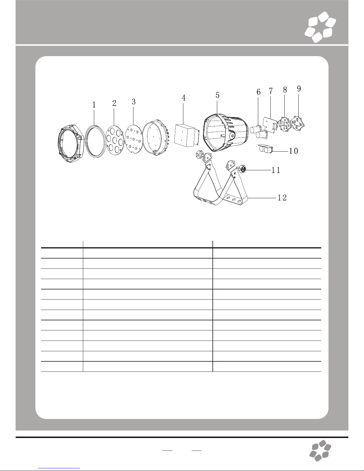
Blow-out Diagram.
1
2
3
4
5
6
7
8
9
10
11
12
Description
Glass cover
LED Lens assembly
LED Metal-core PCB assembly
Electronic Transformer
House
power socket
Display PCB
Display Clear plastic cover
Display watertight seal
DMX socket
Bracket adjustment metal knob
Bracket Assembly
Part Number
6P00609
4170709
2P00609
50801029
P00606
2P00605
803004
6P00613
5050101
5040201
6P00611
5020119
 Loading...