

Page 1
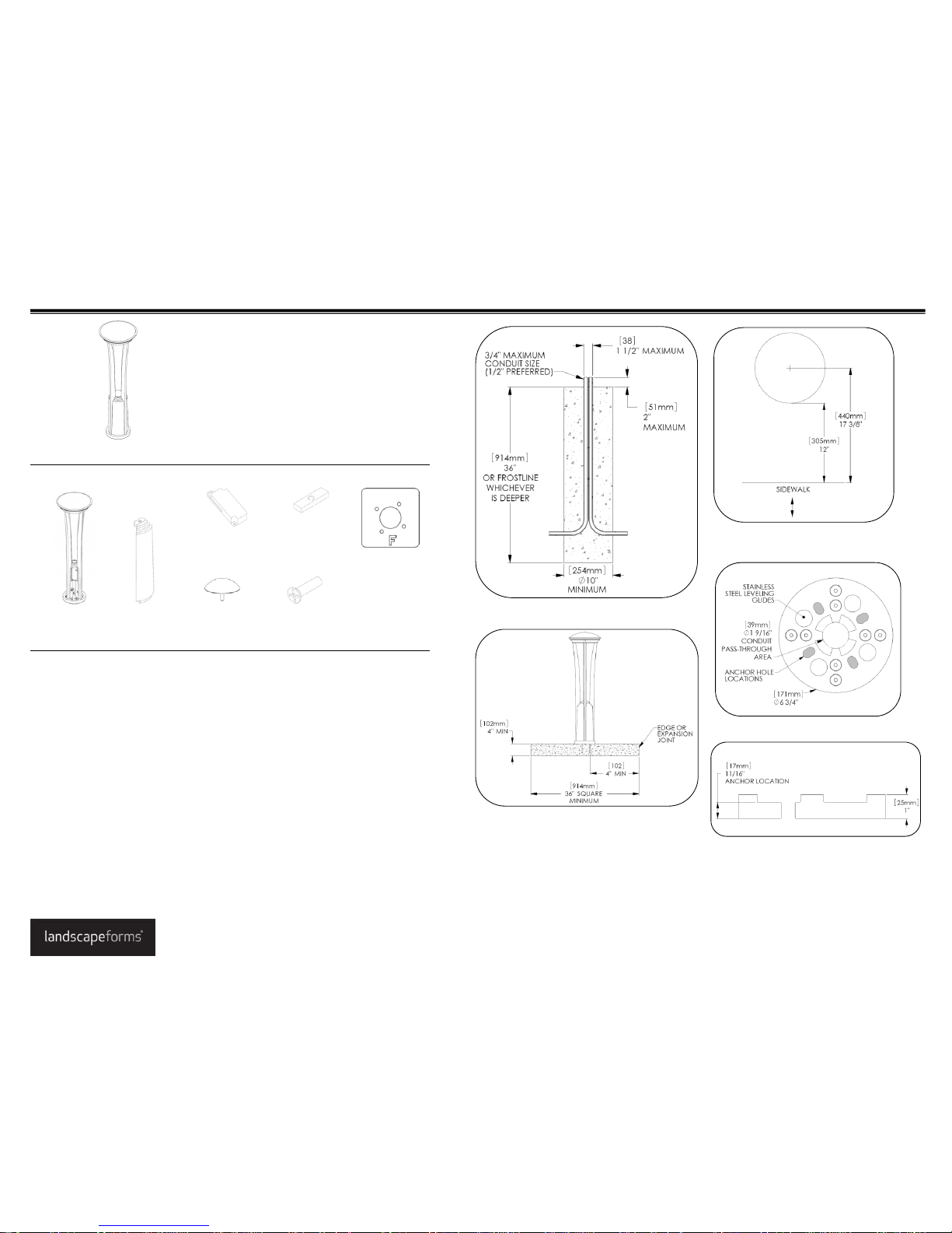
Surface Mount
Included hardware
Fig. 1 – Minimum footing recommendation
Fig. 3 – Recommended setback
from sidewalk
Fig. 4 – Bottom view
Fig. 2 – Minimum concrete slab size
Tools Required
• Safety glasses
• Screwdrivers
• Wiring tools and connectors
• Anchoring hardware – (4) Ø3/8 (maximum) x 3-1/2” length stainless steel anchors.
Landscape Forms recommends Power bolts or drop-in wedge anchors
• Hammer drill
• 3/16” hex key
ASSEMBLE WITH CARE! Pangard II Polyester Powdercoat is a strong, long-lasting finish. To protect
this finish during assembly, place unwrapped powdercoated parts on packaging foam or other nonmarring surface. Do not place or slide powdercoated parts on concrete or other hard or textured
surface – this will damage the finish causing rust to occur. Use touch-up paint on any gouges in the
finish caused by assembly tools.
Fig. 5 – Base plate section view
LIGHTING LAYOUT RECOMMENDATIONS:
Although light pole spacing is the responsibility of others, the following can be used to help
determine appropriate spacing:
Hawthorne distribution is an IES Type 4 pattern and meets or exceeds IESNA DG-5 for Park
walkways, Class 1 bikeways, Residential sidewalks and Intermediate sidewalks at 25’ pole
spacing, and Commercial sidewalks at 15’ pole spacing. Poles can also be spaced 15’ apart
on both sides of a 10’ path for Public-Way Emergency Egress. Outside of North America,
Hawthorne meets CIE-136-2000 for Residential Parks at 25’ pole spacing.
Installation Guide
Hawthorne Pathway Light
www.landscapeforms.com Ph: 800.521.2546
Date: April 14, 2015
Page 1 of 2
1x – Cabinet
dome cover
4x – Cabinet
cover
1x – LED
driver
1x – Cabinet
dome
retainer bar
4x – Cabinet
cover screw
1x – Lightpole
assembly
1x – anchor
template
Page 2
INSTALLATION PROCEDURE FOR LIGHT POLE:
1. Prepare footing as required by local codes, see Fig. 1, Fig. 2 and Fig. 3 for
recommendations.
2. Set wooden anchor template in position over conduit. ‘F’ on the template indicates
the Front of the unit.
3. Mark four anchor hole locations and remove the template.
4. Drill holes according to anchor size and depth. Clear holes of debris.
5. Set unit in place, ensuring that base sits flat on concrete, and install anchors
according to anchor manufacturer’s recommendations.
6. Using 3/16” hex key, adjust leveling glides until unit is plumb.
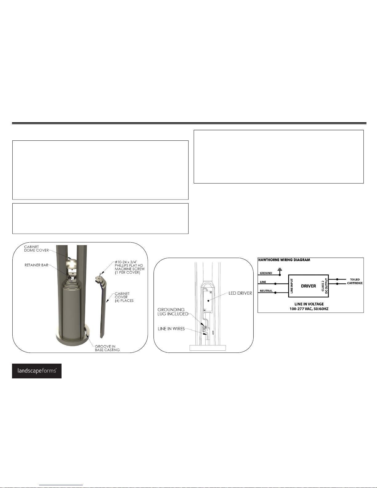
Fig. 6 – Remove access panel
PROCEDURE FOR INSTALLING CABINET COVERS:
1. Set retainer bar in the casting pocket.
2. Install cabinet covers as shown, ensuring bottom tab of cover rests in the groove in
base casting. Repeat for remaining three covers.
3. Install cabinet dome cover by threading into the retainer bar until tight.
PROCEDURE FOR WIRING HAWTHORNE:
The Hawthorne pathway light is assembled at the factory. The light cartridge is
mounted into the head of the pole and will not need to be removed during
installation. The LED cartridge is wired to the driver (located in the cabinet) at the
factory.
The following schematic is to be used to connect the unit to line voltage. It is the
responsibility of the installer to make sure that all connections are made in accordance
with the NEC and local building codes. Connection hardware not included.
Fig. 7 – Access panel removed
Landscape Forms is not responsible for site preparation and footings. Footing
recommendations are included in these instructions.
Installation Guide
Hawthorne Pathway Light
www.landscapeforms.com Ph: 800.521.2546
Page 2 of 2
Date: April 14, 2015
Fig. 8 – Hawthorne Type 4 wiring schematic
 Loading...