

Page 1

No. 2077650(8)
5874PB/5874PBF/VRK5874/VRK5874HF/
PBA6/ PBA7 Valve/Push Button
INSTALLATION, OPERATION
&
MAINTENANCE INSTRUCTIONS
Factory any goods, or part thereof, which shall appear to the Company upon
inspection to be of defective material or not of first class workmanship, provided that
product. Where claims for defects are made, the defective part or parts shall be
delivered to the Company, prepaid, for inspection. HAWS will not be liable for the
made by the owner or his agents, except upon written authority from HAWS,
Sparks, Nevada. HAWS will not be liable for any damages caused by defective
materials or poor workmanship, except for replacements, as provided above. Buyer
claimed to arise under the contract of sale. The drinking fountain manufactured by
HAWS is warranted to function if installation and maintenance instructions provided
also must be used for the purpose for which they were
NOTE TO INSTALLER: Please leave this information with the Maintenance Department.
SHOULD YOU EXPERIENCE DIFFICULTY WITH THE INSTALLATION OF THIS
1455 Kleppe Lane Sparks, NV 89431-6467 (775) 359-4712 Fax (775) 359-7424
E-mail: haws@hawsco.com website: www.hawsco.com
HAWS warrants that this specific product is guaranteed against defective material or
poor workmanship for a period of one year from date of shipment. HAWS liability
under this warranty shall be discharged by furnishing without charge F.O.B. HAWS
claim is made in writing to Haws within a reasonable period after receipt of the
cost of repairs, alterations or replacements, or for any expense connected therewith
agrees that HAWS shall not be liable for general, special, or consequential damages
are adhered to. The units
intended.
NO OTHER WARRANTIES EXPRESSED OR IMPLIED ARE AUTHORIZED,
PROVIDED OR GIVEN BY HAWS.
MODEL PLEASE CALL:
TECHNICAL SUPPORT: 1-800-766-5612
FOR CUSTOMER SERVICE: 1-888-640-4297
07/17 Mod el 5874 P B/58 74 PBF/VRK5874/VRK574HF/PBA6/PBA7 Page 1 of 6
LIMITED WARRANTY
Page 2

Note:
1. Be fo re removing valve, strainer or cartridge assembly, shut off water supply line.
2. This valve is pressure compensating. Be sure to remove any existing flow control
devices. (May be present in fitting or SPUD).
3. Verify that new valve will fit in place of the older 5871 and 5872 series valves. Contact
Haws technical support, if needed.
4. When retrofitting an existing fountain with a 58 74 series valve:
a) Remove any in-line strainer that may be present in the supply l ine,
b) Verify if unit requires a high flow cartridge. If so, follow notes on Page 4 of 6.
c) Valve is directional. Verify flow direction indicated on valve when installing.
d) Reconnect tubing to new valve using your existing fittings.
Caution: Valve must be protected by a 60-mesh strainer LOCATED INSIDE VALVE BODY.
WARRAN TY VOID IF 60-MESH STRAINER IS REMOVED FROM VALVE BODY.
OPERATION & MAINTENANCE OF FRONT ACCESS FEATURES
FLOW ADJUSTMENT: A 3/16” hole in the center of this button is provided for front access to the
adjustment screw found on the cartridge assembly. While pushing the button in and using a slotted
narrow blade scre wdriver, the f low may be adj usted by ins erting it into the hole and tur ning cloc kwise for
increased flow, and counterclockwise for decreased flow.
STRAINER CLEANING: Periodically clean the strainer located inside valve body. Remove front push-
button and retaining nut with the universal spanner wrench provided. Pull cartridge assembly out. Gently
remove strainer off of cartridge. Thoroughly flush away any debris from strainer. Ensure that both the
gasket on cartridge and strainer gasket are very clean with no debris whatsoever, then re-attach strainer
by aligning larger hole opening on gasket over the larger water inlet opening on the cartridge (Don’t
remove gasket that comes with cartridge). Make sure there is no debris in the valve body before inserting
the cartridge assembly back into the valve body. When inserting cartridge assembly, align strainer with
large hole in the valve body, ensure the cartridge has bottomed out by turning slightly into place. Install
retaining nut until it makes contact with the cartridge, then tighten 1 1/4 turn farther; check for leaks.
Reassemble push button per Steps 5, 6, 7 & 10 of installation instructions on Pages 5 & 6.
CARTRIDGE ASSEMBLY REPLACEMENT: Remove front push-button and retaining nut with the
universal spanner wrench provided. Pull cartridge assembly out. Gently remove strainer off of old
cartridge and reassemble on new cartridg e (Don’t remove gask et that comes with c artridge) (See strainer
reattachment instructi ons above). Insert cartr idge assembl y into valve body by aligning sc reen into large
opening inside bottom of valve body. Ensure cartr idge has bottomed out, by tur ning slightly into place.
Install retaining nut until it makes contact with the cartridge, then tighten 1 1/4 turn farther; check for
leaks. Reassemble push button per Steps 5, 6, 7 & 10 of installation instructions on Pages 5 & 6.
STRAINER GASKET REPLACEMENT: Remove front push button and retai ning nut w ith the un iver sal
spanner wrench provided. Pull cartridge assembly out. Gently remove strainer off of cartridge. Ensure
that the gasket on the cartridge is very clean with no debris. Attach new strainer gasket to cartridge (Don’t
remove gasket that comes with cartridge) by aligning larger hole opening on gasket over the larger water
inlet opening on the cartridge. Make sure there is no foreign matter in the valve body before inserting the
cartridge assembly back into the valve body. When inserting cartridge assembly, align strainer with large
hole in the valve body. Ensure the cartridge has bottomed out by turning slightly into place. Install
retaining nut until it makes contact with the cartridge, then tighten 1 1/4 turn farther.
CAUTION: When replacing strainer or cartridge assembly, damage can occur if not
properly re-installed. Read instructions carefully.
PUSH BUTTON ASSEMBLY/REASSEMBLY
Must apply 1 Dot of Loctite 222MS Threadlocker o n fema le threads of push-button. Carefully
follow Steps 5, 6, 7 & 10 on installation drawing (Pages 5 & 6) to ensure proper assembly
procedure.
07/17 Mod el 5874 P B/58 74 PBF/VRK5874/VRK574HF/PBA6/PBA7 Page 2 of 6
Page 3

TROUBLESHOOTING
PROBLEM
REPAIR CHECKLIST
1.
Insufficient water flow.
1a.
Check that the inlet screwdriver stop is in wide open position.
b.
Verify that correct valve cartridge is being utilized for your
c.
Adjust bubbler stream height. See Flow Adjustment
d.
Verify flow direction indicated on valve.
e.
Verify that wave washer is in place and that push button is
f.
Shut off screwdriver stop (not supplied), clean the fine mesh
g.
Verify minimum 30 psi flowing supply pressure.
h.
Shut off screwdriver stop and replace cartridge assembly. See
2.
Water flow too high.
2a.
See steps 1b, 1c or 1e above.
3.
Valve won’t shut off
3a.
Cycle the cartridge assembly by pushing the push-button 5
3b.
Shut off screwdriver stop. Replace cartridge assembly. See
4.
No flow out of valve.
4a.
Check that the inlet screwdriver stop is in wide open position.
b.
Verify flow direction indicated on valve.
c.
Check strainer for possible clogging (see 1f above).
5.
Inconsistent bubbler
stream height.
5a.
See 1f above
6.
Button is loose
6a.
Refer to Installation Drawing Steps 5, 6, 7 & 10 on Pages 5 & 6
7.
Water is leaking out of
7a.
Remove push button with spanner wrench ( P/N 000 69 83506)
b.
If leak persist, shut off screwdriver stop and replace cartridge
application. Models 1920/1920HPS/1920W 1025/1025G
3300/3300G (equipped with a pop-up bubbler head Model
5725) & any models that feature a cuspidor (i.e. 2406, etc.)
require a high flow cartridge (P/N 0001632151) to ensure
proper flow stream height. All other models utilize a standard
flow cartridge.
instructions in Front Access Feature Box.
properly adjusted per Steps 5 & 7 of installation drawing
(Pages 5 & 6).
strainer found inside the 5874 series valve. See Strainer
Cleaning instructions in Front Access Feature Box.
completely
push button assembly.
Cartridge Assembly Replacement instructions in Front Access
Feature Box.
times to clear any foreign matter (if any is present) from the
valve seat.
Cartridge Assembly Replacement instructions in Front Access
Feature Box.
for proper application of Threadlocker 222MS and assembly
procedure.
and tighten retaining nut using same spanner wrench.
assembly. See Cartridge Assembly Replacement instructions
in Front Access Feature Box.
For more information about Haws products, see our website: www.hawsco.com
© 2017 Haws® Corporation – All Rights Reserved
HAWS
07/17 Mod el 5874 P B/58 74 PBF/VRK5874/VRK574HF/PBA6/PBA7 Page 3 of 6
®
and other trademarks used in these materials are the exclusive property of Haws Corporation.
Page 4

THIS DOCUMENT IS TRUE AND CORRECT AT TIME OF PUBLICATION. CONTINUED PRODUCT IMPROVEMENTS
MAKE SPECIFICATIONS AND MEASUREMENTS SUBJECT TO CHANGE WITHOUT NOTICE.
OPTIONAL PCP
***
WASHER FOR
PARTS BREAKDOWN
FLUSH MOUNT
SURFACES (SEE
NOTE BELOW)
5874PB
41
POLISHED CHROME PLATED PUSH BUTTON WITH VALVE
FOR BOTH RECESSED AND FLUSH MOUNT SURFACES.
(ALSO USED FOR REPLACEMENT OF OLDER VALVE
MODELS 5871, 5872, AND 5872HF - SEE NOTE 4.)
5874PBF
1
POLISH CHROME PLATED FLANGE
PUSH BUTTON WITH VALVE FOR
FLUSH MOUNT SURFACES ONLY.
0006983506
SPANNER WRENCH
(ONLY INCLUDED WITH MODELS:
5874PB & 5874PBF)
VRK5874
1
VALVE REPAIR KIT
(STANDARD FLOW)
DO NOT REMOVE
GASKET WHICH COMES
WITH CARTRIDGE.
2
VRK5874HF
VALVE CARTRIDGE
DO NOT REMOVE
GASKET WHICH COMES
WITH CARTRIDGE.
5
2
3
(HIGH FLOW)
PBA6
POLISHED CHROME PLATED
FLANGED PUSH BUTTON FOR
FLUSH MOUNT SURFACES ONLY.
IF NEEDED, USE 1-3/4" O.D. X .050 THICK PCP
***
WASHER PN 0006729529 (NOT SUPPLIED) IN
POLISHED CHROME PLATED PUSH
BUTTON FOR BOTH RECESSED
AND FLUSH MOUNT SURFACES.
PBA7
SITUATIONS WHERE THE PUSH BUTTON HOLE IS
SLIGHTLY OVERSIZED FOR THE 5874PB RING NUT.
NOTES:
1 MODELS 5874PB, 5874PBF, AND VRK5874 ARE EQUIPPED WITH A STANDARD FLOW CARTRIDGE.
ORDER THESE MODELS WHEN REPLACING/REPAIRING VALVES WITH A STANDARD FLOW APPLICATION.
DO NOT USE ON ANY MODELS THAT FEATURE A CUSPIDOR OR HAVE A HIGH FLOW APPLICATION
WITHOUT IMPLEMENTING ADDITIONAL REQUIRED STEPS (SEE NOTES 2 AND 3).
0003244389
THREADLOCKER TO
SECURE PUSH BUTTON
(ONLY INCLUDED W/PB SERIES)
0002568123
3
GASKET W/SCREEN
0006626653
WAVE WASHER FOR USE WITH
BOTH RECESSED AND FLANGED
STYLE PUSH BUTTON ASSEMBLIES.
(MUST BE IN PLACE FOR PROPER
PUSH BUTTON OPERATION)
2 MODELS 1025/G AND 3300/G EQUIPPED WITH A POP-UP BUBBLER HEAD (MODEL 5725) AND MODEL
VRK5874HF, 2406 (EQUIPPED WITH A CUSPIDOR) AND 1920 SERIES BOTTLE FILLER MODELS ALL
UTILIZE A HIGH FLOW CARTRIDGE TO ENSURE PROPER FLOW.
3 WHEN REPLACING A HIGH FLOW CARTRIDGE ASSEMBLY, DO NOT USE VRK5874; USE VRK5874HF.
4 FOR VALVE REPLACEMENT ON UNITS WITH OLDER 5871, 5872 (STANDARD FLOW) AND 5872HF (HIGH FLOW) VALVES:
CONTACT HAWS TECHNICAL SUPPORT.
5 VRK5874HF IS ALSO USED ON 1920 SERIES BOTTLE FILLER MODELS (SEE NOTE 2).
ECN:
5216
DATE
06/08/16
DATE
BYECN NO.
CHKD
07/25/17
MODEL(S)
JP
JP
SCALE:
5874PB/5874PBF/VRK5874/VRK5874HF/
NA
PBA6/PBA7.
DRAWING TYPE: SIZE: A
PARTS BREAKDOWN
REVISED PER
4250
DRAWN
WHEN ORDERING PARTS PLEASE SPECIFY MODEL NUMBER.
C
2017
Haws Corporation - All Rights Reserved
HAWS and other trademarks used in these materials are the exclusive property of Haws Corporation.
R
LM
APPROVED
FV
1455 KLEPPE LANE
SPARKS, NEVADA 89431
(775) 359-4712 FAX (775) 359-7424
E-MAIL: HAWS@HAWSCO.COM
WEBSITE: WWW.HAWSCO.COM
PAGE
PART NUMBER
0002077650
REVISION
8
SHEET OF
11
4 OF 6
Page 5

THIS DOCUMENT IS TRUE AND CORRECT AT TIM E OF PUB L ICATION. CONTINUED PRODUCT IMPROVEME NTS
MAKE SPECIFICATIONS AND MEASUREMENTS SUBJECT TO CHANGE WITHOUT NOTICE.
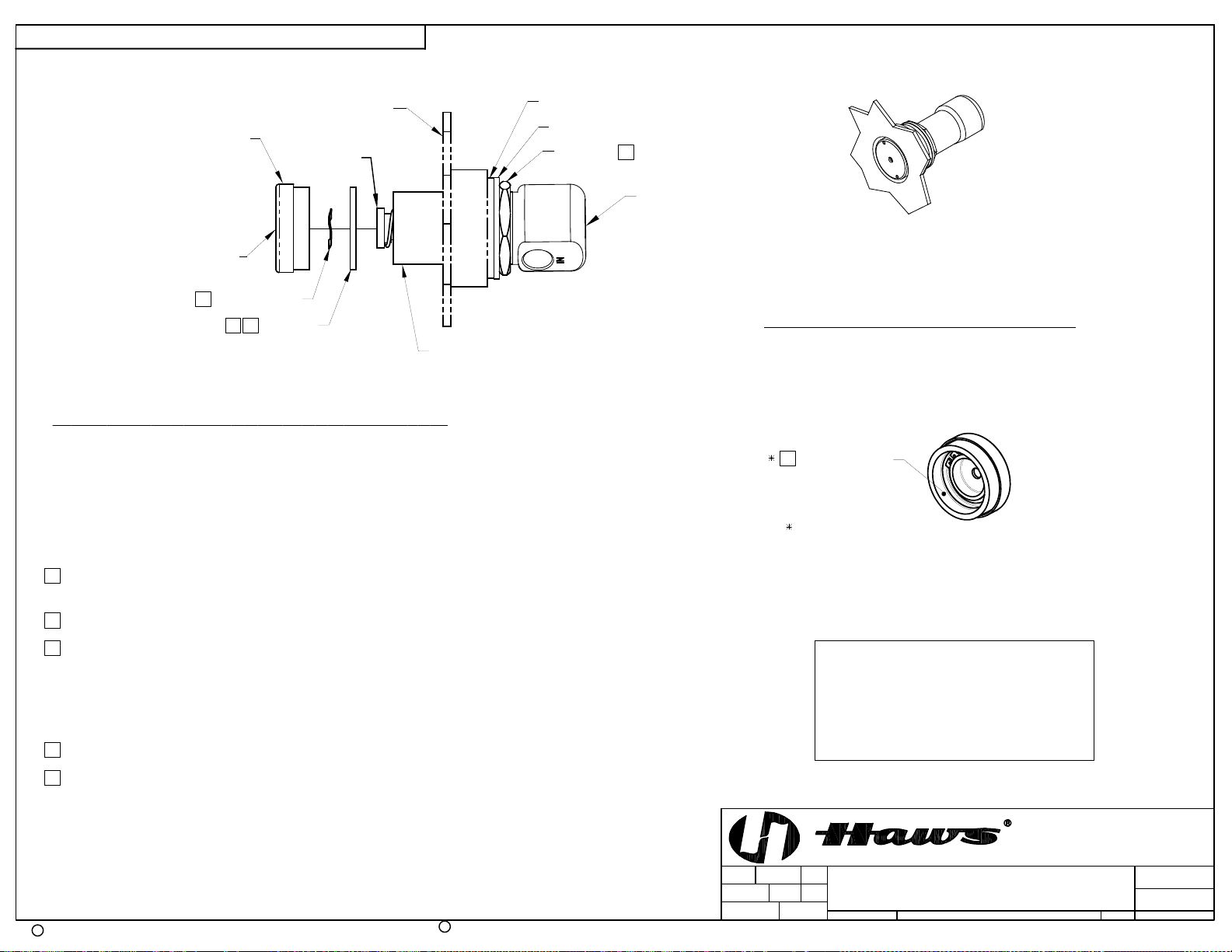
(FRONT OF FOUNTAIN)
FLANGED
PUSH BUTTON
CARTRIDGE
RUBBER WASHER
FIBER WASHER
LOCK NUT
CARTRIDGE ***
(DO NOT REMOVE GASKET
THAT COMES WITH CARTRIDGE)
9
5 OF 6
VALVE BODY
FRONT ADJUST
SCREW ACCESS
2X 1/4" IPS CONNECTION
5
*** WAVE WASHER
(FITTINGS NOT SUPPLIED)
GASKET W/SCREEN ***
LARGE RING NUT
4
8
VALVE SHOWN MOVED
FORWARD ABOUT 1" (STEP 3).
*** MODEL VRK5874 & VRK5874HF- VALVE REPAIR KITS INCLUDE THESE ITEMS
INSTALLATION INSTRUCTIONS FOR 5874PBF.
1) FOLLOW INSTRUCTIONS CAREFULLY ON O&M MANUAL (PAGE 2 OF 6) WHEN REMOVING
OLD VALVE. NOTE: SEE PARTS BREAKDOWN (PAGE 4 OF 6) FOR ADDITIONAL NOTES.
2) VERIFY THAT LOCK NUT, FIBER, AND RUBBER WASHERS ARE POSITIONED SLIGHTLY
PAST MIDWAY OF THREADS ON NEW VALVE BODY.
3) INSERT VALVE INTO BRACKET FROM INSI DE AND PUSH FORWARD ABOUT 1".
4 THREAD LARGE RING NUT ONTO VALVE BODY, A PPROXIMATELY 1" INTO VALVE.
5 PLACE WAVE WASHER INSIDE OF FLANGED PUSH BUTTON ASSEMBLY (MUST BE IN PLACE).
6 APPLY ONE (1) DOT OF LOCTITE 222MS, ON THE FEMALE THREADS OF BUTTON ASSEMBLY
LEAVING THE FIRST AND LAST THREADS FREE. (FIGURE 1). CAUTION: EXCESS LOCTITE CAN
CAUSE THREADS TO LOCK VERY TIGHTLY, MAKING REPAIRS DIFFICULT.
**7) THREAD FLANGED PUSH BUTTON ASSEMBLY ON VALVE UNTIL WAVE WASHER MAKES SLIGHT
CONTACT WITH STEM OF CARTRIDGE. CAUTION: DO NOT HAND-TIGHTEN.
ASSEMBLED 5874PBF
(FLUSH MOUNT APPLICATION)
SEE SHEET 2 OF 2 FOR RECESSED MOUNT INSTRUCTIONS.
APPLY 1 DOT OF
6
LOCTITE 222MS
(WHERE SHOWN)
THIS ALSO APPLIES
TO PBA6
FIGURE 1
NOTE!
THIS VALVE IS PRESSURE COMPENSATING.
BE SURE TO REMOVE ANY EXISTING FLOW
CONTROL DEVICES. (MAY BE PRESE NT IN
FITTING OR SPUD).
PAGE
8 UNTHREAD RING NUT FORWARD UNTIL IT STOPS FLUSH WITH PUSH BUTTON ASSEMBLY.
9 PUSH VALVE BACK TOWARD THE INSIDE OF BRACKET AND TIGHTEN LOCKNUT (SEE
ILLUSTRATION ABOVE).
10) TIGHTEN PUSH BUTTON ASSEMBLY USING UNIVERSAL SPANNER WRENCH PROVIDED.
** OVERTIGHTENING WILL PRE-ACTUATE VALVE AND CAUSE WEEPAGE, WHILE NOT ENO UGH
CONTACT BETWEEN WAVE WASHER AND STEM CAN CAUS E A LOW FLOW CONDITION.
C
2017
Haws Corporation - All Rights Reserved.
HAWS and other trademarks used in these materials are the exclusive property of Haws Corporation.
R
4250
DRAWN:
LM
APPROVED:
FV
REVISED PER
ECN:
5216
DATE:
06/08/16
DATE:
BY:ECN NO.
CHK'D.:
07/25/17
MODEL(S)
JP
GC
SCALE:
1455 KLEPPE LANE
SPARKS, NEVADA 89431
(775) 359-4712 FAX (775) 359-7424
E-MAIL: HAWS@HAWSCO.COM
WEBSITE: WWW.HAWSCO.COM
5874PB/5874PBF/VRK5874/VRK5874HF/
NA
DRAWING TYPE: SIZE: A
PBA6/PBA7
INSTALLATION
PART NUMBER
0002077650.D
REVISION
8
SHEET OF
12
Page 6
THIS DOCUMENT IS TRUE AND CORRECT AT TIM E OF PUB L ICATION. CONTINUED PRODUCT IMPROVEME NTS
MAKE SPECIFICATIONS AND MEASUREMENTS SUBJECT TO CHANGE WITHOUT NOTICE.
RUBBER WASHER
FIBER WASHER
LOCK NUT
9
CHROME RECESSED
PUSH BUTTON
(FRONT OF FOUNTAIN)
CARTRIDGE
VALVE BODY
(SEE SHEET
1 OF 2 FOR
FRONT ADJUST
DETAILS)
SCREW ACCESS
5
WAVE WASHER
84
RING NUT
VALVE SHOWN MOVED
FORWARD ALL THE WAY (STEP 3)
INSTALLATION INSTRUCTIONS FOR 5874PB.
1) FOLLOW INSTRUCTIONS CAREFULLY ON O&M MANUAL (PAGE 2 OF 6) WHEN REMOVING
OLD VALVE. NOTE: SEE PARTS BREAKDOWN (PAGE 4 OF 6) FOR ADDITIONAL NOTES.
2) VERIFY THAT LOCK NUT, FIBER WASHER, AND RUBBER WASHERS ARE POSITIONED TOWARD
BOTTOM END OF THREADS ON NEW VALVE BODY.
3) INSERT VALVE INTO BRACKET FROM INSIDE, AND PUSH ALL THE WAY FORWARD
(SEE ILLUSTRATION ABOVE).
4 THREAD RING NUT ONTO VALVE BODY, AS FAR IN AS POSSIBLE, TOWARD FRONT OF FOUNTAIN.
NOTE: IF REPLACING A 5871 OR 5872 SERIES VALVE, YOU MAY HAVE TO CONTACT HAWS TECHNICAL SUPPORT.
ASSEMBLED 5874PB
(RECESSED MOUNT APPLICATION)
SEE SHEET 1 OF 2 FOR FLUSH MOUNT INSTRUCTIONS.
APPLY 1 DOT OF
6
LOCTITE 222MS
(WHERE SHOWN)
THIS ALSO APPLIES
TO PBA7
FIGURE 1
6 OF 6
PAGE
5 PLACE WAVE WASHER INSIDE OF PUSH BUTTON ASSEMBLY (MUST BE IN PLACE).
6 APPLY ONE (1) DOT OF LOCTITE 222MS, ON THE FEMALE THREADS OF BU TTON ASSEMBLY
LEAVING THE FIRST AND LAST THREADS FREE. (F IGURE 1). CAUTION: EXCESS LOCTITE CAN
CAUSE THREADS TO LOCK VERY TIGHTLY, MAKING REPAIRS DIFFICULT.
**7) THREAD PUSH BUTTON ASSEMBLY ON VALVE UNTIL WAVE WASHER MAKES SLIGHT
CONTACT WITH STEM OF CARTRIDGE. CAUTION: DO NOT HAND-TIGHTEN.
8 UNTHREAD RING NUT FORWARD UNTIL IT STOPS FLUSH WITH PUSH BUTTON ASSEMBLY.
9 PUSH VALVE BACK TOWARD THE INSIDE OF BRACKET AND TIGHTEN LOCKNUT (SEE
ILLUSTRATION ABOVE).
10) TIGHTEN PUSH BUTTON ASSEMBLY USING UNIVERSAL SPANNER WRENCH PROVID ED.
** OVERTIGHTENING WILL PRE-ACTUATE VALVE AND CAUSE WEEPAGE, WHILE NOT ENOUGH
CONTACT BETWEEN WAVE WASHER AND STEM CAN CAUSE A LOW FLOW CONDITION.
C
2017
Haws Corporation - All Rights Reserved.
HAWS and other trademarks used in these materials are the exclusive property of Haws Corporation.
R
4250
DRAWN:
LM
APPROVED:
FV
REVISED PER
ECN:
5216
DATE:
06/08/16
DATE:
NOTE!
THIS VALVE IS PRESSURE COMPENSATING.
BE SURE TO REMOVE ANY EXISTING FLOW
CONTROL DEVICES. (MAY BE PRESENT IN
FITTING OR SPUD).
BY:ECN NO.
MODEL(S)
JP
CHK'D.:
07/25/17
GC
5874PB/5874PBF/VRK5874/VRK5874HF/
SCALE:
NA
DRAWING TYPE: SIZE: A
PBA6/PBA7
1455 KLEPPE LANE
SPARKS, NEVADA 89431
(775) 359-4712 FAX (775) 359-7424
E-MAIL: HAWS@HAWSCO.COM
WEBSITE: WWW.HAWSCO.COM
INSTALLATION
PART NUMBER
0002077650.D
REVISION
8
SHEET OF
22
 Loading...