

Page 1
Model 6518.2FR
INSTALLATION, OPERATION
&
MAINTENANCE INSTRUCTIONS
No. 2077791(21)
warrants that this specific product is guaranteed against defective material or
under this warranty shall be discharged by furnishing without charge F.O.B. HAWS
any goods, or part thereof, which shall appear to the Company upon
inspection to be of defective material or not of first class workmanship, provided that
claim is made in writing to Haws within a reasonable period after receipt of the
ms for defects are made, the defective part or parts shall be
delivered to the Company, prepaid, for inspection. HAWS will not be liable for the
cost of repairs, alterations or replacements, or for any expense connected therewith
Nevada. HAWS will not be liable for any damages caused by defective materials or
poor workmanship, except for replacements, as provided above. Buyer agrees that
arise under the contract of sale. The drinking fountain manufactured by HAWS is
warranted to function if installation and maintenance instructions provided are
ose for which they were
NOTE TO INSTALLER: Please leave this information with the Maintenance Department.
SHOULD YOU EXPERIENCE DIFFICULTY WITH THE INSTALLATION OF THIS
1455 Kleppe Lane Sparks, NV 89431-6467 (775) 359-4712 Fax (775) 359-7424
E-mail: haws@hawsco.com website: www.hawsco.com
HAWS
poor workmanship for a period of one year from date of shipment. HAWS liability
Factory
product. Where clai
made by the owner or his agents, except upon written authority from HAWS, Sparks,
HAWS shall not be liable for general, special, or consequential damages claimed to
adhered to. The units also must be used for the purp
intended.
NO OTHER WARRANTIES EXPRESSED OR IMPLIED ARE AUTHORIZED,
PROVIDED OR GIVEN BY HAWS.
MODEL PLEASE CALL:
TECHNICAL SUPPORT: 1-800-766-5612
FOR CUSTOMER SERVICE: 1-888-640-4297
LIMITED WARRANTY
09/16 Model 6518.2FR Page 1 of 9
Page 2
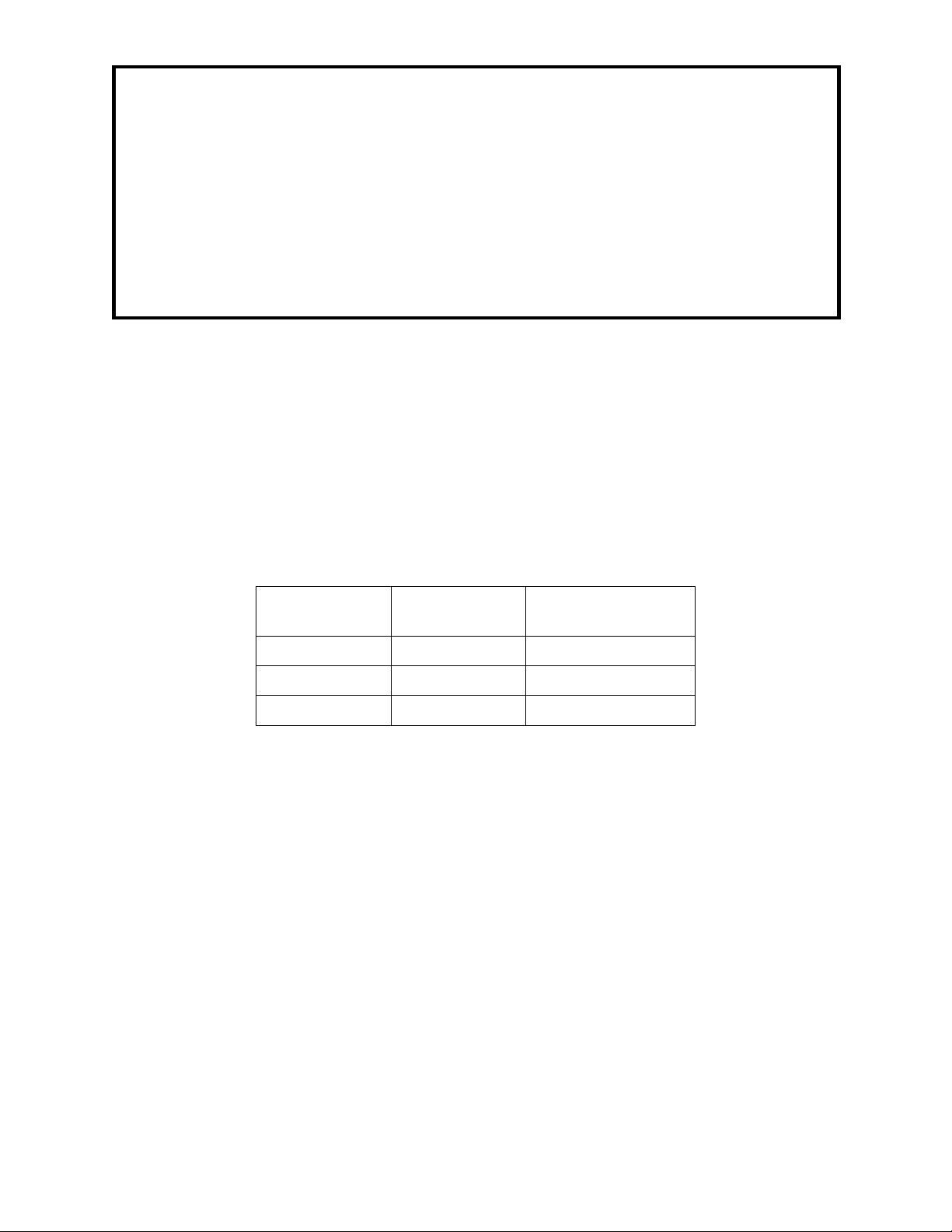
RECOMMENDED TOOLS: Pipe joint sealant, screwdriver, level, 5/64” hex key wrench, 12”
O.D.
1/4”
±.005”
11/16”
3/8”
±.005”
3/4”
1/2”
±.005”
7/8”
adjustable wrench, 10” pipe wrench, 5/16”, 3/4”, 9/16”, 1/2” and 7/16” open end wrenches.
LOCATION OF UNIT: The Model 6518.2FR is suitable for all season out-door use where
temperatures may drop well below freezing. This model is used with HAWS outdoor drinking
fountains and jug fillers. When installing this unit, local state or federal codes should be
adhered to.
SUPPLY LINE: The minimum recommended line size is 1/2” IPS with 30-90 psi (2-6 ATM)
flowing pressure. Where sediment or mineral content in water is a problem, an inlet filter is
recommended.
PLUMBING CONNECTIONS: Inlet valve is 1/2” IPS male, which must be buried below the
frost line. Waste outlet is female 1-1/4” outside diameter tailpiece.
INSTALLATION PROCEDURE
GENERAL NOTES:
1. For all plastic push-in type fitting connections, only connect NSF-61 copper or
plastic tubing. Stainless steel or glass tubing is not recommended. The
following assembly instructions must be followed to ensure a watertight
connection:
a. Cut tubing square and clean.
b. Mark from end of tube the length of insertion (See table below).
c. Push tube into the fitting until it bottoms out.
d. To remove, depress collet and pull tubing out.
Tube Sizes
Tolerance
Insertion Depth
Refer to installation drawing for details. Use pipe joint sealant on all water connections.
STEP 1: Trench for water supply and waste drain lines. The hole should be deep enough to
accommodate the PVC casing and a minimum of 10 cubic feet of porous fill (gravel).
Additional porous fill and drain pipe may be required due to local ground conditions.
Provide a shut-off valve for maintenance. Install the 1/2" supply line and 1-1/4”
sanitary drain, (see Installation Drawing sheet 2 of 3), excavation detailed drawing.
Cut the PVC pipe to fit desired bury depth, but no less than 40" long.
STEP 2: Attach the supply hose assembly to the inlet elbow below the frost line
(see Installation Drawing sheet 3 of 3). Lower the PVC pipe into place. Then with
PVC primer and glue attach the “Y” fitting to the pipe. Pull the supply assembly up
through the casing using the attached metal rod. Flush the line before attaching the
valve.
09/16 Model 6518.2FR Page 2 of 9
Page 3

INSTALLATION PROCEDURE
STEP 3: Attach the valve assembly to the hose assembly outside of the casing. Pressure
test for leaks: Using the metal rod as a handle, lower the complete valve assembly
into casing. Make sure that the supply hose coils into the bottom of the casing
without any kinks. Keep the hose coiled underneath the valve (see Installation
Drawing sheet 1 of 3). Cap the casing and back-fill the trench. Keep the valve casing
vertical at all times.
STEP 4: Locate the fountain anchor bolts in the proper position. Care must be taken to insure
clearance within the pedestal for the valve casing branch arm waste drain line. Pour
concrete into forms and finish. Let concrete set for at least 24 hours.
STEP 5: Place the fountain onto the mounting pad and secure in place. Pull the valve
assembly out of the valve casing. Feed the supply tubing from the fountain down into
the valve casing branch arm. Reach into the top of the casing and pull the tubing out.
Tubing should now run from pedestal operator down through valve casing arm, then
up valve casing to ground level. Measure and cut the tubing to length, allowing
enough tubing, to reach the bottom of valve casing. Connect tubing from fountain to
the push-in type fitting outlet of the valve. Connect the waste line to the fountain.
STEP 6: Feed t he two 5/32" O.D. t ubing from the valve up to the fountain through the valve
casing branch arm. Connect the tubing with label to the push button. Secure with the
compression nut (hand tight only). Leave the end of the attached breather tube open
to the air.
STEP 7: Turn on the supply line shutoff valve. Test the 6518.2FR valve using the fountain
push button. Check for leaks. Refer to trouble shooting section for any malfunction.
STEP 8: Lower the complete valve assembly back into the casing as in Step 3. T est the flow
once again and make sure that the line water between valve and fountain drains
back to porous fill. Make sure the tubing has no low spots, which might collect water
causing ice plugs in freezing weather.
STEP 9: When the fountain operates satisfactorily, install the access plates. Place a piece of
insulation foam (provided) inside the casing as shown on installation drawing. To
complete installation, cap valve casing and replace valve box cover.
09/16 Model 6518.2FR Page 3 of 9
Page 4

TROUBLESHOOTING
PROBLEM
REPAIR CHECKLIST
1.
Bubbler Flow Control.
1. Adjust pressure regulator:
a.
Loosen the locknut.
b.
Rotate the knob clockwise to increase
flow or counterclockwise to reduce flow.
c.
Tighten the locknut.
d.
Lower the valve assembly back into the
casing.
e.
Repeat the above steps until the
bubbler flow is correct.
f.
Replace pressure regulator if
necessary.
2.
Insufficient bubbler flow.
2.
a.
Check that the main shut-off valve is
wide open.
b.
Verify minimum 30 psi supply pressure.
c.
Clean inlet strainer screen located in the
valve body.
d.
Adjust Pressure Regulator (Refer to
Step 1).
3.
No flow.
3.
a.
Check for leaks in the air tubing going
b.
Make sure the air tubing compression
c.
Disconnect air tube from push button
d.
Disconnect air tube from push button.
4.
Continued insufficient or varied height
of bubbler flow.
4.
a.
Check for kinks in the tubing.
b.
Adjust Pressure Regulator (Refer to
Step 1).
from the push button to the valve.
nuts are hand tight.
assembly. Blow into tube to verify valve
function. Replace valve if necessary.
Place finger over air outlet. Push button
to test diaphragm. Tighten diaphragm
cap screws. Replace diaphragm if
necessary.
09/16 Model 6518.2FR Page 4 of 9
Page 5

TROUBLESHOOTING
PROBLEM
REPAIR CHECKLIST
5.
Continuous bubbler flow.
5.
a.
Insure that push button is not obstructed
b.
Remove four screws, which secure
(older models, integral brass seat).
c.
If valve seat was OK and diaphragm
disc over or replace disc.
d.
If diaphragm and seats are in good
plate.
e.
Insure that air bleed port on valve
and springs back to normal position.
plastic diaphragm block to brass valve
body. Pull plastic and rubber diaphragm
assembly out of valve body. Locate tiny
hole in rubber diaphragm just under lip
of plastic part. Clean debris from this
hole. Inspect valve seat for grooves. If
seat is worn, replace with stainless steel
seat (newer models) or replace valve
holes were free from debris, inspect
rubber button located at center of
floating steel disc in valve diaphragm
block assembly. If button is worn, turn
For more information about Haws products, see our website: www.hawsco.com
© 2016 Haws
HAWS
09/16 Model 6518.2FR Page 5 of 9
®
®
Corporation – All Rights Reserved
and other trademarks used in these materials are the exclusive property of Haws Corporation.
condition, stretch spring slightly. Spring
is located behind floating stainless steel
plastic block assembly is not plugged.
Page 6

THIS DOCUMENT IS TRUE AND CORRECT AT TIME OF PUBLICATI ON. CONTINUED PRODUCT IMPROVEMENTS
MAKE SPECIFICATI ONS AND MEASUREMENTS SUBJECT TO CHANGE W ITHOUT NOTICE.
5/32" O .D. TUBING (NOT SUPPLIED)
5/32" O.D. TUBING (NOT SUPPLIED)
DISC
1/2" NPT (F)
STRAINER
CLEANOUT
SEAT
SPRING
DIAPHRAGM
VRK2AV
(VALVE REPAIR KIT)
VRK3AV (COVER, BLACK COLOR)
THIS BLACK COVER IS NOT INTE RCHANGEABLE
WITH GRAY COVERS USED ON OLDER 5881 VALVES.
(SCRE WS & WASH ERS NOT SUPPLI ED WITH C OVERS ) .
0006040013
BREATHER TUBING
0006040013
ACTUATIO N TUBIN G
5867 PRESSURE
REGULATOR
5881
VALVE ASSEMBLY
(EXPLODE D VIE W)
1/2" NPT (F)
VRK3AV
DETAIL
0003264260 NIPPLE
6518FRDV
DRAIN VALVE
5815 CHECK VALVE
0003097993 HOSE
5881
VALVE
ASSEMBLY
ECN:
5137
DATE
08/26/04
DATE
BYECN NO.
CHKD
10/24/16
CC
VWC
MODEL(S)
6518.2FR
VALVE, FREEZE RESISTANT, DUAL
DRAWING TYPE: SIZE: A
SCALE:
1:1
PARTS BREAKDOWN
REVISED PER
DRAWN
WHEN ORDERING PARTS PLEASE SPECIFY MODEL NUMBER.
C
2016
Haws Corporation - All Rights Reserved
HAWS and other trademarks used in these materials are the exclusive property of Haws Corporation.
R
M.D.
APPROVED
FV
1455 KLEPPE LANE
SPARKS, NEVADA 89431
(775) 359-4712 FAX (775) 359-742 4
E-MAIL: HAWS@HAWSCO.COM
WEBSITE: WWW.HAWSCO.COM
PAGE
PART NUMBER
0002077791
REVISION
21
SHEET OF
11
6 OF 9
Page 7

C
Haws Corporation - All Rights Reserved.
2016
HAWS and other trademarks used in these materials are the exclusive property of Haws Corporation.
MAKE SPECIF ICATIONS AND M E AS UREMENTS SU BJ E CT TO CHANGE WI T HOUT NOTICE.
THIS DOCUME NT IS TRUE A ND CORRECT AT TIME OF PUBLICATION. CON T INUED PRODUCT IMPROVEMENTS
FROST LINE
MINIMUM 5 CUBIC FEET POROUS
GRAVEL F IL L (N O T SU PPL IED)
R
TO FROST LINE
457mm
18"
MIN.
(SUPPLY HOSE ASS' Y SU PPLIED )
(TO ATMOSPHERE ABOVE GROUND)
(UNION NOT SUPPLIED)
RIGID 1/2" IPS FITTINGS
(DO NOT OVERTIGH TE N)
F.D.A. AND NSF APPROVED
HIGH PRESSU RE HOSE.
SECURE 1" CLAMP
BREAT H ER TUBIN G
AROUND 1/2" ELBOW
3/8" SUPPLY TUBING
ACTUATION TUBING
(TO PUSH BUTTON)
4 1/2" MIN
114mm
APPROVED:
FV
DATE:
10/24/16
SCALE:
1:13
DRAWING TYPE: SIZE: A
INSTALLATION
VALVE, FREEZE RESISTANT, DUAL
CJL
09/22/92
VWC
DRAWN:
ECN:
DATE:
5137
CHK'D.:
CC
6518.2FR
REVISED PER
BY:ECN NO.
MODEL(S)
WEBSITE: WWW.HAWSCO.COM
914mm
36"
1/2" IPS SUPPLY FROM
SHUTOFF (NOT SUPPLIED).
PVC PIPE, TRIM TO
LIFT ROD WITH SUPPLIED 1" CLAMP
(USE TO LOWER/RAISE VALVE ASSEMBLY)
(VALVE ASS'Y)
CHECK VALVE
DESIRED LENGTH.
5867 PRESSURE REGULATOR (SEE NOTE 1)
FOAM INSULATION
PVC "Y" ASSEMBLY
(NOT SUP PL IED)
INSULATION
216mm
1702mm
914mm
36"
67"
TO
MAX.
MIN.
(775) 359-4712 FAX (775) 359-7424
E-MAIL: HAWS@HAWSCO.COM
SPARKS, N EVADA 89431
1455 KLEPPE LANE
REMOVABLE CAP
8-1/2"
VALVE BO X (N O T SUPPLIED)
SIZE: 12-1/4" H X 19" W X 25-1/2" L
(311mm H X 482mm W X 648mm L)
0002077791.D
REVISION
PART NUMBER
SHEET OF
13
21
PAGE
7 OF 9
Page 8

MAKE SPECIFICATIONS AND MEASUREMENTS SUBJECT TO CHANGE WITHOUT NOTICE.
C
Haws Corporation - All Rights Reserved.
2016
THIS DOCUMEN T IS TRUE AN D CORRECT AT TIME OF P UBLICA TION. CONTINUED PRODUCT IMPR OVEMENT S
610mm
24"
HAWS and other trademarks used in these materials are the exclusive property of Haws Corporation.
305mm
12"
MIN.
102mm
4"
MIN.
R
(AT BASE)
1270mm
50"
DIA.
FROST LINE
90°
(NOT SUPPLIED)
WASTE
1-1/4" IPS
±4" [102mm]
90°
635mm
OPENING
2134mm
84"
25"
DIA.
127mm
MIN.
5"
APPROVED:
DRAWN:
CJL
FV
REVISED PER
ECN:
DATE:
09/22/92
5137
DATE:
10/24/16
CHK'D.:
BY:ECN NO.
VWC
CC
SCALE:
MODEL(S)
1:24
VALVE , FREEZE RESISTANT, DUAL
DRAWING TYPE: SIZE: A
6518.2FR
INSTALLATION
0002077791.D
REVISION
PART NUMBER
SHEET OF
23
21
WEBSITE: WWW.HAWSCO.COM
90°
GRAVEL FILL (NOT SUPPLIED)
MINIMUM 5 CUBIC FEET POROUS
305mm
12"
(NOT SUPPLIED)
1/2" IPS SUPPLY
FINISHED GRADE
MIN.
INSTALLATION INSTRUCTIONS).
REQUIRED DEPT H BELOW
FROST LINE. (REFER TO
BELOW FROST LINE
635mm
(775) 359-4712 FAX (775) 359-7424
E-MAIL: HAW S@HAWSCO.COM
SPARKS, NEVADA 89431
1455 KLEPPE LANE
25"
MIN.
PAGE
8 OF 9
Page 9

C
Haws Corporation - All Rights Reserved.
2016
HAWS and other trademarks used in these materials are the exclusive property of Haws Corporation.
R
MAKE SPECIFICATIONS AND MEASUREMENTS SUBJECT TO CHANGE WITHOUT NOTICE.
THIS DOCUMENT IS TRUE AND CORRECT AT TIME OF PUBLICATION. CONTINUED PRODUCT IMPROVEMENTS
GROUND LEVEL
CONCRE TE SL AB
(NOT SUPPLIED)
30" SQ UARE
1/2"-UNC BOLTS
APPROVED:
FV
DATE:
10/24/16
SCALE:
1:24
VALVE, FREEZE RESISTANT, DUAL
DRAWING TYPE: SIZE: A
INSTALLATION
CONCRET E ANCHORS
DRAWN:
CJL
REVISED PER
ECN:
DATE:
09/22/92
5137
MINIMUM 5 CU BIC FEET POR OUS
BY:ECN NO.
CHK'D.:
VWC
CC
GRAVEL FILL (NOT SUPPLIED)
VALVE BOX (NOT SUPPLIED)
REMOVA BLE CAP
MODEL(S)
DESIRE D LE NGTH.
PVC PIPE, TRIM TO
PVC "Y" ASSEMBLY
PACKED SA ND
FROST LINE
6518.2FR
0002077791.D
REVISION
PART NUMBER
SHEET OF
33
21
WEBSITE: WWW.HAWSCO.COM
(775) 359-4712 FAX (775) 359-7424
E-MAIL: HAWS@HAWSCO.COM
SPARKS, N EVADA 89431
1455 KLEPPE LANE
PAGE
9 OF 9
 Loading...