

Page 1
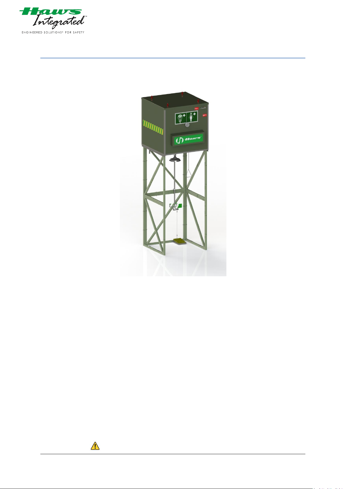
4000.12 Tank Shower
Picture 1: Cover picture
Project name: Tag No.: Project No. Haws: Order No.: -
Manufacturer: Haws AG
Bachweg 3
CH-3401 Burgdorf
Switzerland
Document version: 140556 v1
Date of issue: 08.08.2014
Before starting all tasks, read the operating instructions!
4000.12_V1 2014.08.08 Autor: tara
©Haws AG Switzerland Confidential Page 1
Page 2

TABLE OF CONTENTS
1 GENERAL INFORMATION .......................................................................................................................................... 3
1.1 STANDARDS: ................................................................................................................................................................................. 3
1.2 SCHEDULE .................................................................................................................................................................................... 3
1.3 INFORMATION CONCERNING THIS DOCUMENTATION ................................................................................................................ 3
1.4 SYMBOL EXPLANATION ................................................................................................................................................................ 4
1.5 DISCLAIMER .................................................................................................................................................................................. 5
1.6 WARRANTY CONDITIONS ............................................................................................................................................................. 5
1.7 CUSTOMER SERVICE AND PRODUCT MONITORING ..................................................................................................................... 5
2 SAFETY INFORMATION ............................................................................................................................................. 6
3 DESCRIPTION ............................................................................................................................................................ 6
3.1 CORRECT USE TO THE INTENDED PURPOSE ................................................................................................................................. 6
3.2 NAME PLATE ................................................................................................................................................................................ 7
3.3 OVER HEAD TANK SHOWER ......................................................................................................................................................... 7
3.1 DELIVERY INCLUDES ..................................................................................................................................................................... 9
4 GENERAL ARRANGEMENT ....................................................................................................................................... 10
5 P & ID PROCESSSCHEMASTICS ................................................................................................................................ 11
6 CONTROLS .............................................................................................................................................................. 12
7 SPARE PARTS .......................................................................................................................................................... 13
7.1 SPARE PART LIST ......................................................................................................................................................................... 14
7.2 RECOMMENDED SPARES FOR 2 YEARS CONTINUOUS OPERATION ............................................................................................ 15
7.3 MATERIAL OF CONSTRUCTION ................................................................................................................................................... 16
8 WIRING DRAWING .................................................................................................................................................. 17
9 INSTALLATION AND ERECTION INSTRUCTION ......................................................................................................... 18
9.1 CONDITIONS ............................................................................................................................................................................... 18
9.2 ASSEMBLY INSTRUCTION ........................................................................................................................................................... 19
9.3 CONNECTION LIST ...................................................................................................................................................................... 25
9.4 CHECKLIST AFTER ERRECTING / YEARLY CHECKUP ..................................................................................................................... 25
9.4.1 PRE-COMMISSIONING PROCEDURE ................................................................................................................................ 26
9.4.2 COMMISSIONING PROCEDURE ........................................................................................................................................ 26
9.5 BRIEFING OF PERSONNEL AND ORGANISATION OF MAINTENANCE .......................................................................................... 27
10 SITE ACCEPTANCE PROTOCOL ................................................................................................................................. 28
11 MAINTENANCE ....................................................................................................................................................... 30
11.1 MAINTENANCE SCHEDULE ......................................................................................................................................................... 30
11.2 MAINTENANCE REPORT ............................................................................................................................................................. 31
11.3 TROUBLE SHOOTING .................................................................................................................................................................. 33
12 MANUALS / DRAWINGS & CERTIFICATES OF COMPONENTS ................................................................................... 34
12.1 HEATING CABLE GM 2X .............................................................................................................................................................. 34
12.2 END SEAL KIT E-150 .................................................................................................................................................................... 34
12.3 POWER CONNECTION KIT C-150-E ............................................................................................................................................. 34
12.4 JUNCTION BOX GIFAS TYPE 3020 ............................................................................................................................................... 34
12.5 THERMOSTAT RAYSTAT CONTROL 10 ......................................................................................................................................... 34
12.6 INDUCTIVE SENSOR IS M12 ........................................................................................................................................................ 34
12.7 BIMETAL THERMOMETER Model 52 .......................................................................................................................................... 34
13 CERTIFICATION HAWS............................................................................................................................................. 35
14 DECLARATION OF CONFORMITY HAWS .................................................................................................................. 36
15 LIST OF FIGURES ..................................................................................................................................................... 37
4000.12_V1 2014.08.08 Autor: tara
©Haws AG Switzerland Confidential Page 2
Page 3

1 GENERAL INFORMATION
1.1 STANDARDS:
- EN ISO 12100-1:2011
- EN 15154-3:2009
- EN 15154-4:2009
- EN 60204-1:2006
- EN10244:2005
- ANSI Z358.1
1.2 SCHEDULE
Purchase Order: PO and clarification of all technical aspects Delivery date:
02.06.2014 30.07.2014 12.08.2014
1.3 INFORMATION CONCERNING THIS DOCUMENTATION
Use of documentation This documentation serves as a guideline for normal course of
trouble-free operations with safety showers model 4000.
Targed group This documentation is designed for:
Installation designers/Planners
Installers
Operators
Tester
Repairmen
Requisition to read this documentation This documentation must be read carefully by any person who
is or will be responsible for using, maintaining or repairing this
equipment. Please contact the manufacturer / supplier if you
are uncertain or have any questions.
Storage location of this documentation This documentation is an integral part of the Safety
equipement and should be accessable for all persons in
charge.
Reselling products In case the product should be passed on to a successive user
then the operating and maintenance instructions must also be
included.
Concomitant regulations,
guidelines and norms Besides the advices in this opearting instruction, please also
regard the advices and signs on the safety-equipement.
Furthermore, the local accident prevention regulations and
general safety conditions for the application of the
Safetyequipement are also applicable.
Illustrations in this documentation The illustrations in this guide are for the purpose of
explanation and may differ from the actual design of your
safety shower.
4000.12_V1 2014.08.08 Autor: tara
©Haws AG Switzerland Confidential Page 3
Page 4

1.4 SYMBOL EXPLANATION
In these instructions, safety instructions are designated by symbols. The safety instructions are initiated by key
words that express the extent of the hazard. It is imperative to adhere to safety instructions and act with
caution in order to prevent accidents, personal injury and material damage.
DANGER !
… points to an immediately dangerous situation, which will lead to death or serious injuries if it is not avoided
_____________________________________________
WARNING !
… points to a potentially dangerous situation, which will lead to death or serious injuries if it is not avoided
_____________________________________________
CAUTION !
… points to a potentially dangerous situation, which may lead to minor or light injuries if it is not avoided
_____________________________________________
ATTENTION !
… points to a potentially dangerous situation, which may lead to property damage if it is not avoided.
_____________________________________________
NOTICE !
… emphasizes useful hints and recommendations as well as information for efficient and trouble-free
operation.
_____________________________________________
4000.12_V1 2014.08.08 Autor: tara
©Haws AG Switzerland Confidential Page 4
Page 5

1.5 DISCLAIMER
Information in this documentation All information and notes in this manual were compiled under
consideration of valid standards and regulations, the present
status of technology and our years of knowledge and
experience. The actual scope of delivery can, by special
designs, deviate from the explanations and presentations
given here, because of the utilization of additional order
options, or because of the most recent technical changes.
Shipment The responsibilities agreed in the delivery contract, the
General Terms and Conditions as well as the delivery
conditions of the manufacturer and the statutory regulations
valid at the time of the conclusion of the contract are
effective.
Technical modifications The manufacturer reserves the right to make technical
modifications according to legal regulations stipulating the
continual improvement of product features and safety.
exclusion of liability The manufacturer will not guarantee against any accident
caused by caused by the following:
Use not according to regulations
On non-observance of this operating manual and its
operating instructions
Work or handle on this safetyepuipement by non-qualified
personnel
Use of spare parts other than those from the original
manufacturers
Alterations, additions or maintenance without the written
approval of manufacturer
use of unsuitable operating equipment
1.6 WARRANTY CONDITIONS
Reference The guarantee conditions shall be as stipulated in the sales
contract and General Terms of Business of the manufacturer.
General It will be up to the manufacturer to decide on the warranty
claim. The event of any action that falls under warranty the
original warranty period will not be prolonged and no new
warranty will be given.
If repairs during the warranty period are carried out by
operator or third partys without the manufacturers written
permission, the warranty will expire immediately.
1.7 CUSTOMER SERVICE AND PRODUCT MONITORING
Customer service If any problems are encountered during installation or
operation which cannot be resolved with the aid of the
installation and maintenance instructions, please contact the
supplier or manufacturer for more information.
Product monitoring The common aim is to continuously improve our safety
products, processes and services for customers. Furthermore,
our employees are always interested in new information and
experience arising from use and which can be valuable for the
improvement of our products.
4000.12_V1 2014.08.08 Autor: tara
©Haws AG Switzerland Confidential Page 5
Page 6

2 SAFETY INFORMATION
WARNING !
Faulty installation.
Negligent maintenance.
Tripping hazards and barriers on your way to the safety
shower.
Mortal danger!
Risk of loss of eyesight!
Danger of permanent damage to health!
This safety shower shall safe life and eye sight:
Do not risk the effectiveness of the safety shower by
unprofessional installation.
Check weekly the function of the safety shower and
provide immediate troubleshooting.
Please ensure at all time that there are no tripping hazards
and barrieres on the way to the safety shower.
_____________________________________________
Personal Protective Equipement • Wear personal safety equipment in accordance with the
relevant local regulations.
3 DESCRIPTION
3.1 CORRECT USE TO THE INTENDED PURPOSE
The safety shower
- 4000.12 combination unit
Is a
- Body shower with water and additive inlet connection at
storage tank.
In combination with an
- Integrated eyewash with water supply connection to
storage tank.
and meets the requirements of
- Non plumbed-in body showers according to
EN 15154-3:2009
and
- Non plumbed-in eyewash units according to
EN 15154-4:2009
Any other use is not according to the directives
NOTICE !
Use for the intended purpose also includes observation of the appropriate INSTALLATION AND ERECTION
INSTRUCTION instruction Page 18 including compliance with the CONDITIONS Page 18 and regular
MAINTENANCE Page 30.
_____________________________________________
4000.12_V1 2014.08.08 Autor: tara
©Haws AG Switzerland Confidential Page 6
Page 7
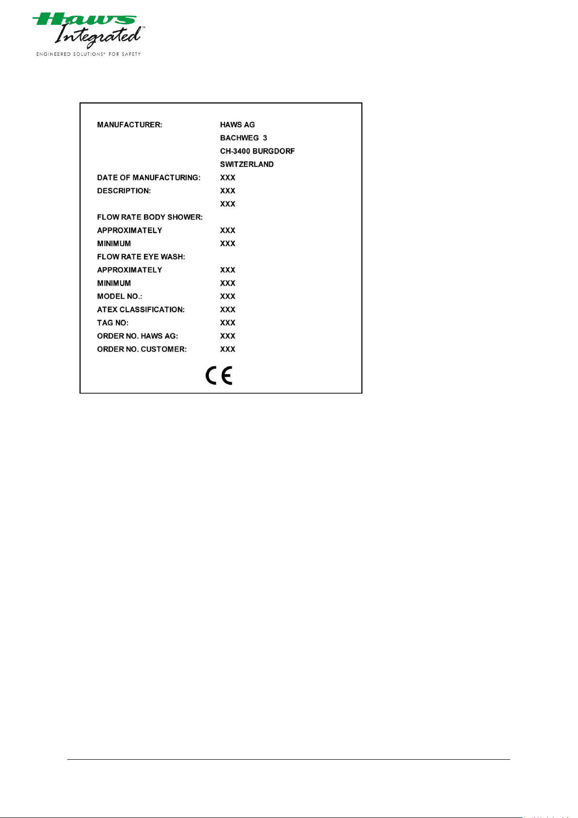
3.2 NAME PLATE
Picture 2: Name plate
3.3 OVER HEAD TANK SHOWER
HAWS Integrated model 4000.12 is a self contained combination shower with a 1200 liter over head tank.
The shower is driven by gravitiy of the water column.
Optional: The water tank can be ordered heat traced and insulated for
outdoor application. With this option the water temperature
can be set between 25-28°C.
The HAWS Integrated model 4000.12 is designet according ANSI Z358.1. However the gravity fed tank shower
do not meet ANSI Z358.1 because the flow performance is not constant for the entire flushing time of 15
minutes.
The tank capacity lasts for at least 15 minutes flushing time of body shower and eyewash. The stainless steel
tank incorporates a water level indicator and a temperature gauge.
The cabin offers enough space for two people.
Frame, side walls and roof are made of stainless steel.
The frame can be anchored to the ground. The tank comes with lifting lugs for easy erection.
The body shower has an average capacity of approx. 60l/min. The flow decreases due to the static height of
water level decreases.
The eyewash has a capacity of 6l/min and lasts for at least 9 minutes during simultaneous operation with the
body shower.
The combination shower signs are according to ISO 3864-1 & ANSI Z358.1 standard. In addition a green-white
tape around the cabin is included.
4000.12_V1 2014.08.08 Autor: tara
©Haws AG Switzerland Confidential Page 7
Page 8

One bottle of water preservative is included in the scope of supply.
OPTIONAL:
- An inductive alarm sensor is connected to the level
indicator. The sensor will be activated if the water level
drops below the set point.
- Tank is insulated and heat traced. The water temperature
will be controlled by Thermostat and scald valve.
4000.12_V1 2014.08.08 Autor: tara
©Haws AG Switzerland Confidential Page 8
Page 9

3.1 DELIVERY INCLUDES
The Tank shower Model 4000.12 will be tailored to include the following:
- 1x 1200lt Tank (stainless steel). Heat traced and insulated.
(25-28°C)
- 1x Eye wash, mounted inside (Stainless steel).
Activated by foot treadle (Stainless steel). Capacity of
approx. 6l/min
- 1x Body shower (Stainless steel) Capacety of approx.
60l/min.
- 1x tank case (Stainless steel) including green/yellow
marking
- 6x Frame elements (Stainless steel)
- 1x Set of Eye wash and shower sign in jumbo size.
- 1x Inductive alarm sensor
- 1x thermostat Raystat control 10
- 1x scald valve
- 1x heating cable
- Voltage: 230V/ 50Hz.
- 1x Water connection 1 1/4" BSP male
- 1x temperature sensor PT-100
Weight of this unit: ca. 370kg
Dimensions: 1.05m x 1.13m x 3.56m (Length x Width x Height)
4000.12_V1 2014.08.08 Autor: tara
©Haws AG Switzerland Confidential Page 9
Page 10
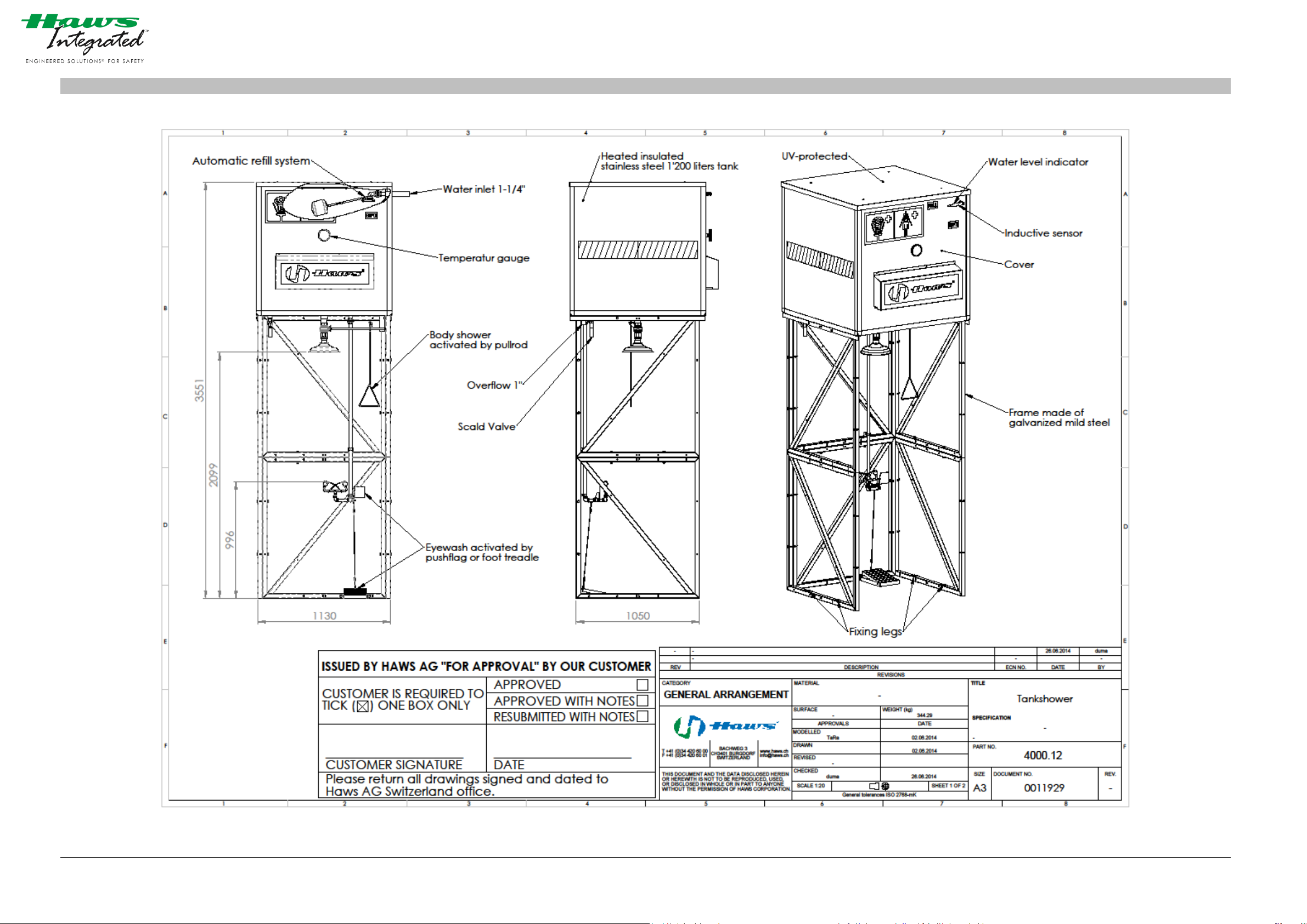
4 GENERAL ARRANGEMENT
Picture 3: Drawing of GA Haws
4000.12_V1 2014.08.08 Autor: tara
©Haws AG Switzerland Confidential Page 10
Page 11
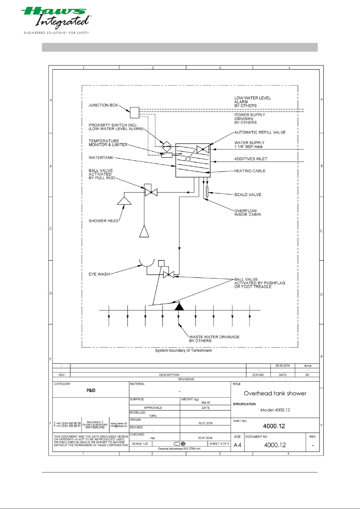
5 P & ID PROCESSSCHEMASTICS
Picture 4: P&ID Drawing
4000.12_V1 2014.08.08 Autor: tara
©Haws AG Switzerland Confidential Page 11
Page 12
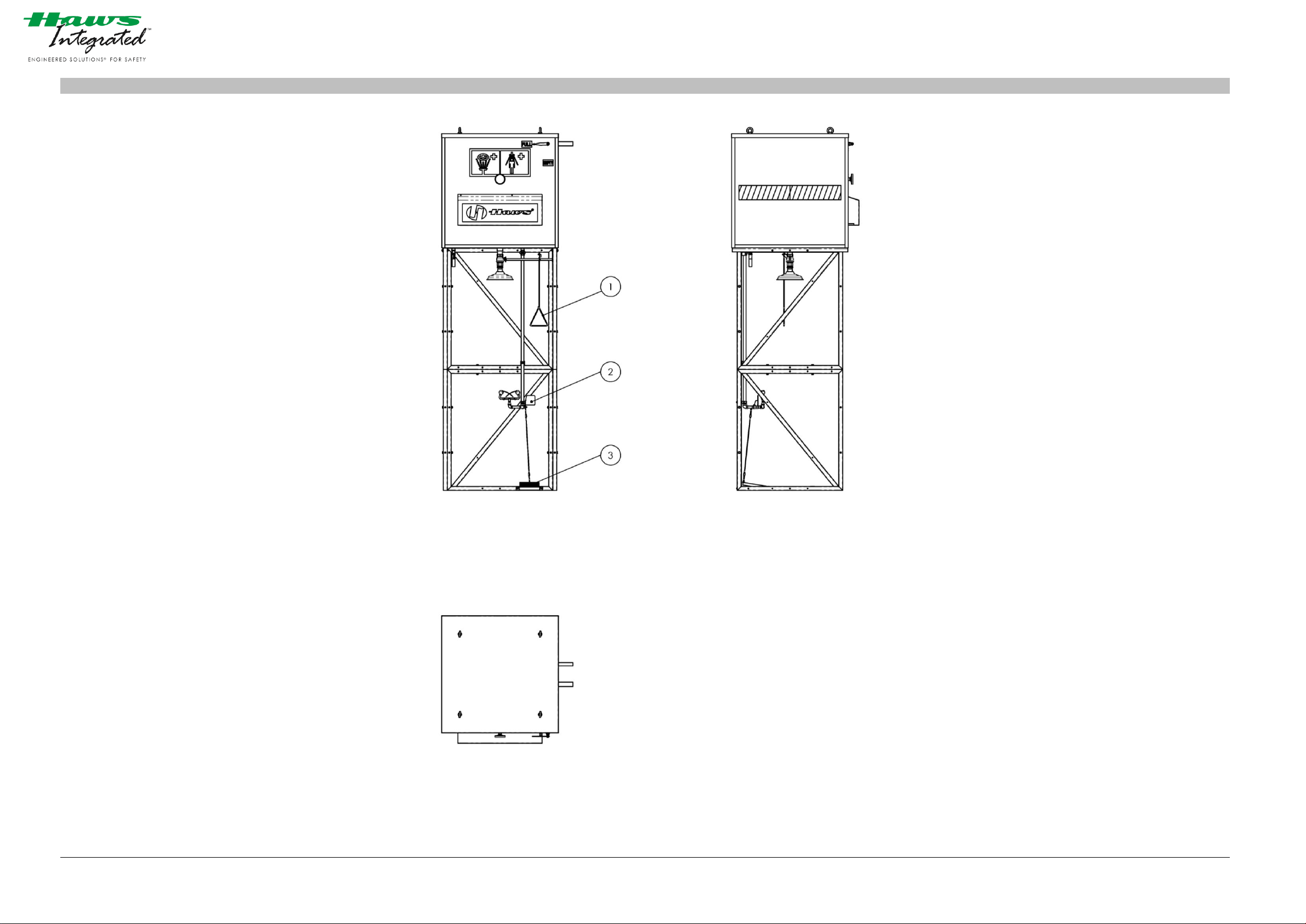
Picture 5: controls
1. Pull rod
To activate: pull down
To turn off: pull up
2. Push flag
To activate: Push down
To turn off: Pull up
3. Grate
To activate: step on.
To turn off: step off and pull the pushflag up [2.]
6 CONTROLS
4000.12_V1 2014.08.08 Autor: tara
©Haws AG Switzerland Confidential Page 12
Page 13
7 SPARE PARTS
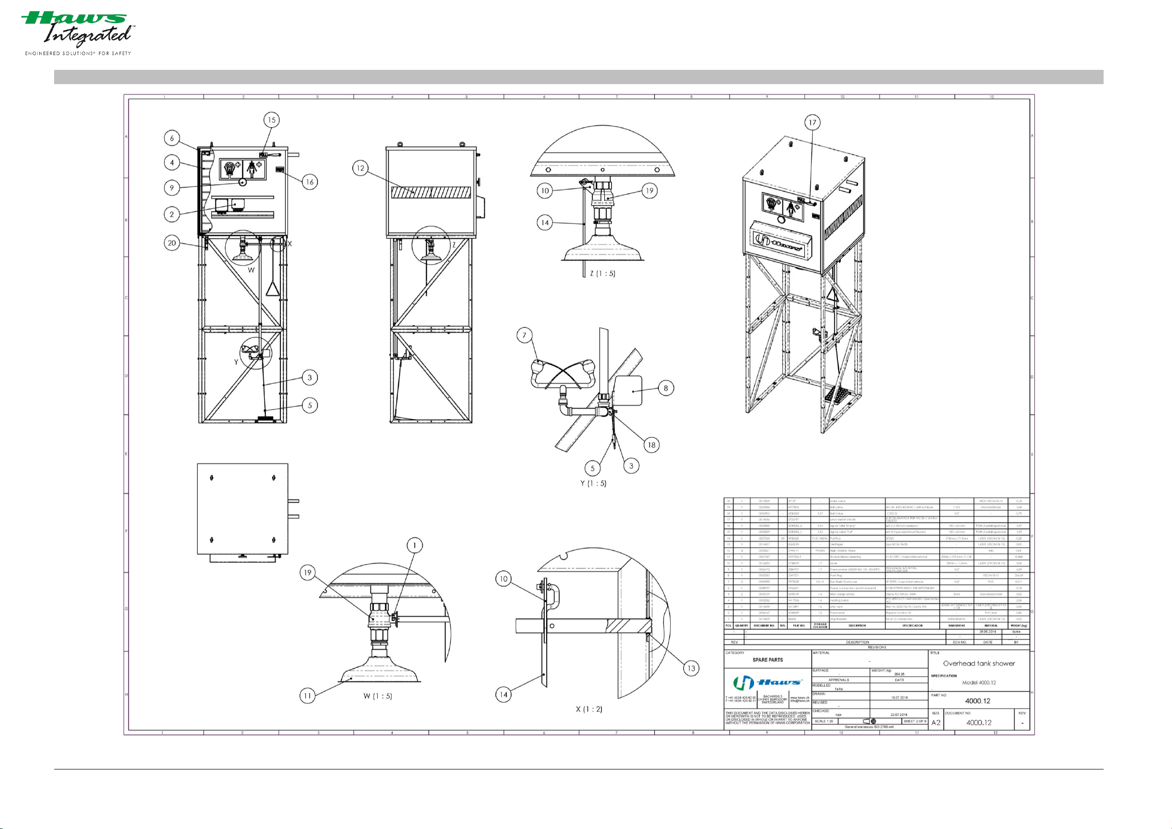
Picture 6: Drawing of spare parts
4000.12_V1 2014.08.08 Autor: tara
©Haws AG Switzerland Confidential Page 13
Page 14
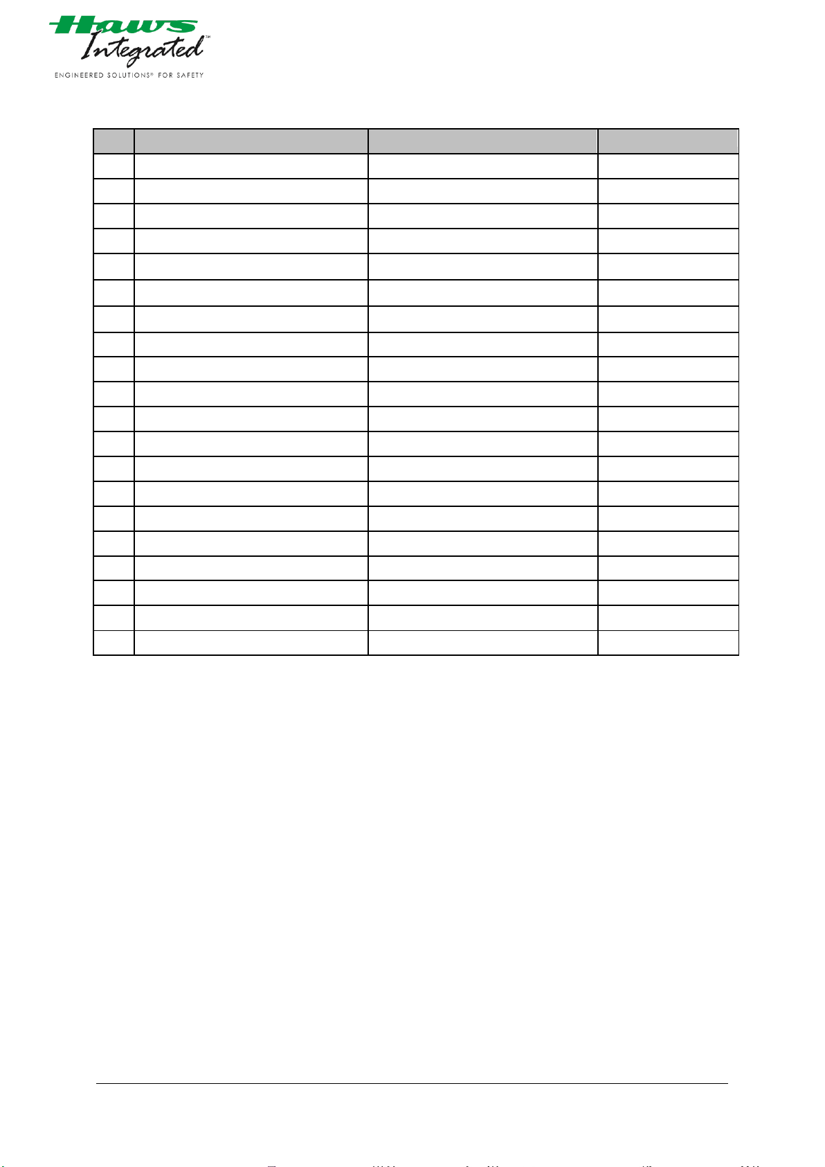
7.1 SPARE PART LIST
No.
DESCRIPTION
Part No.
Drawing Pos. No.
1.
Stop Bracket
86606
1
2.
Thermostat
1038399
2
3.
Wire rope
1412491/L1220
3
4.
Heating band
1417006
4
5.
Wire clamp eiform
1698149
5
6.
Power connection & End seal kit
1746601
6
7.
Eye wash dust cover
1973025
7
8.
Push flag
2347201
8
9.
Thermometer A5209 NG 100-30+50°C
2580707
9
10.
Lever
2758075
10
11.
Shower Head assembly
2927824.5
11
12.
High visibility stripe
3196111
12
13.
Bush bearing
4265010
13
14.
Pull Rod
4950620
14
15.
Signal Label “Full”
5250054_1
15
16.
Signal Label “Empty”
5250054_2
16
17.
Proxy switch
5726797
17
18.
Ball valve
6550269
18
19.
Ball valve
6575876
19
20.
Scald valve
SP157
20
4000.12_V1 2014.08.08 Autor: tara
©Haws AG Switzerland Confidential Page 14
Page 15

No.
DESCRIPTION
Part No.
Drawing Pos. No.
1.
Stop bracket
86606
1
2.
Wire rope
1412491/L1220
3
3.
Eye wash dust cover
1973025
7
4.
Lever
2758075
10
5.
Bush bearing
4265010
13
6.
Scald valve
SP157
20
7.2 RECOMMENDED SPARES FOR 2 YEARS CONTINUOUS OPERATION
4000.12_V1 2014.08.08 Autor: tara
©Haws AG Switzerland Confidential Page 15
Page 16
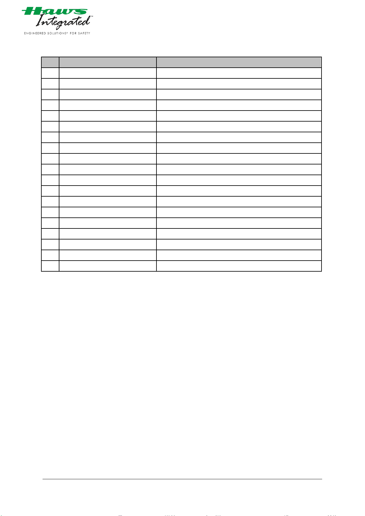
7.3 MATERIAL OF CONSTRUCTION
No.
DESCRIPTION
Material construction
1.
Thermostat
Polycarbonate
2.
Wire rope
Stainless steel
3.
Heating band
Fluoropolymer, copper braid, Modified polyolefin, copper
4.
Power connection & End seal kit
Engineering polymers, Silicone rubber, Stainless steel
5.
Wire Clamp
Galvanized steel
6.
Eye Wash-Dustcover
Plastics
7.
Thermometer
Stainless steel
8.
Shower head
Stainless steel
9.
Level switch (sensor)
brass nickel-plated, Kepital F25 POM, Lexan 923/A
10.
Test tag
ABS / paper
11.
Ball Valve
Stainless steel
12.
Ball Valve
chromed brass
13.
Eye wash
Stainless steel
14.
Frame
Stainless steel
15.
casing
Stainless steel
16.
Tank
Stainless steel
17.
Grate
Galvanized steel
18.
Pipes and Fittings
Stainless steel
19.
Screws, washer, nuts
Stainless steel
4000.12_V1 2014.08.08 Autor: tara
©Haws AG Switzerland Confidential Page 16
Page 17
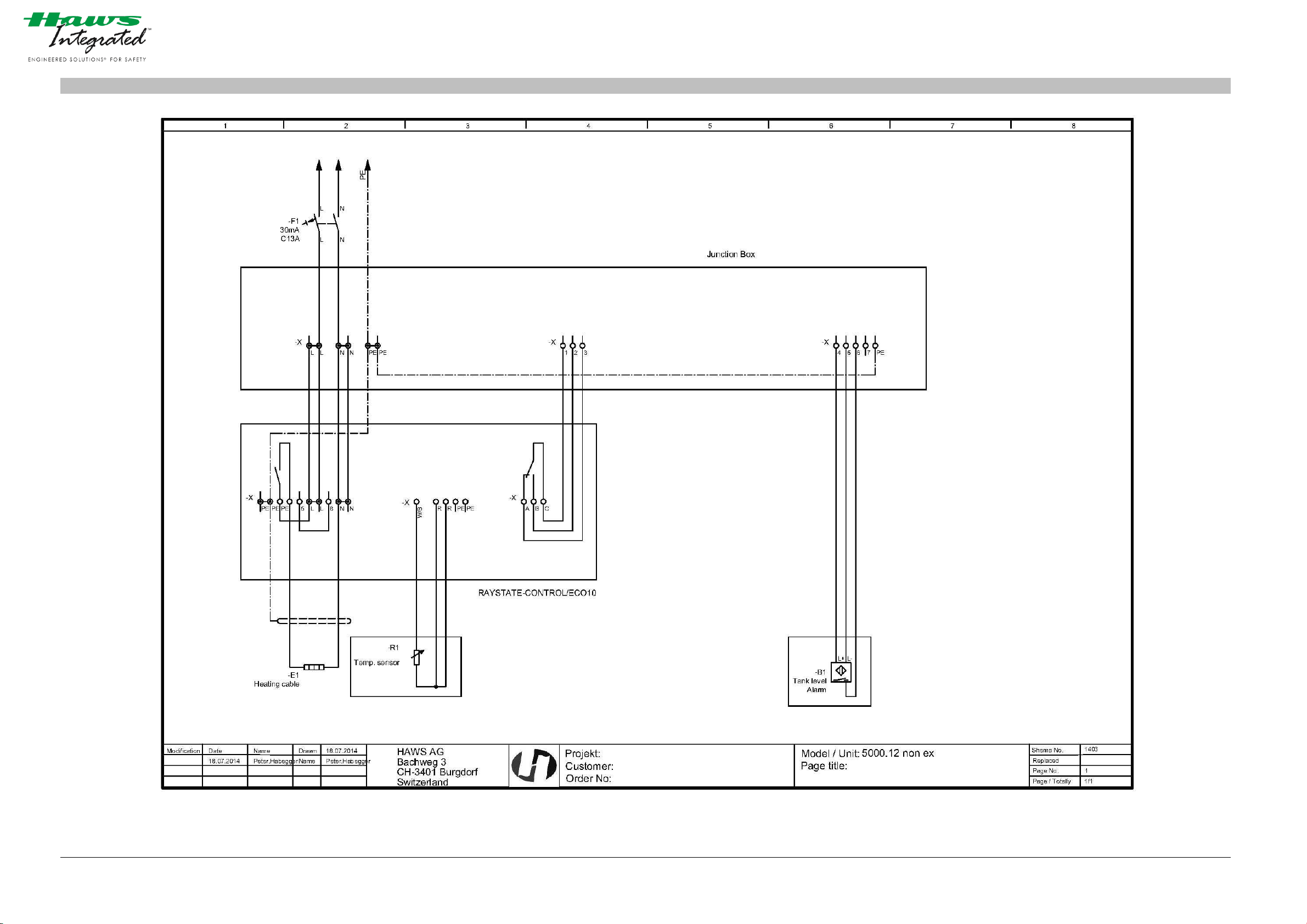
8 WIRING DRAWING
Picture 7: Wiring diagram
4000.12_V1 2014.08.08 Autor: tara
©Haws AG Switzerland Confidential Page 17
Page 18

9 INSTALLATION AND ERECTION INSTRUCTION
NOTICE !
Use for the intended purpose also includes the compliant design and standards of safety showers and correct
installation methods in accordance with the description below.
9.1 CONDITIONS
Personnel requirements • Sanitary specialist
Resources needed • 4000 Tankshower unit
Valves, adapter, strainer, tubes etc. according to local
legislation or conditions.
(not included in the scope of delivery)
Hemp or PTFE tape for thread sealing
(not included in the scope of delivery)
Mounting material for anchoring to the ground
(not included in the scope of delivery)
Installation tools for sanitary equipement
(not included in the scope of delivery)
Installation location • 4000 Tankshower unit
The showers are reachable on short ways by persons who
require first aid treatment
(please note the difficult for the injured person to orient
and move by themselves during emergency situations) this
means:
- Within 10 Seconds
- On same level as the source of danger
- No tripping hazards and barrieres on the way to the
safety shower
- Well illuminated
- Signboards of emergency safety shower must remain
visible in the work area.
- On hazards caused by strong acids and alkalis the safety
shower needs to be situated byside hazardous area
Watersupply:
- drinking water or water of the same quality according
to european or national standards
No electrical installations near the splash area
4000.12_V1 2014-08-08 Autor: tara
©Haws AG Switzerland Confidential Page 18
Page 19
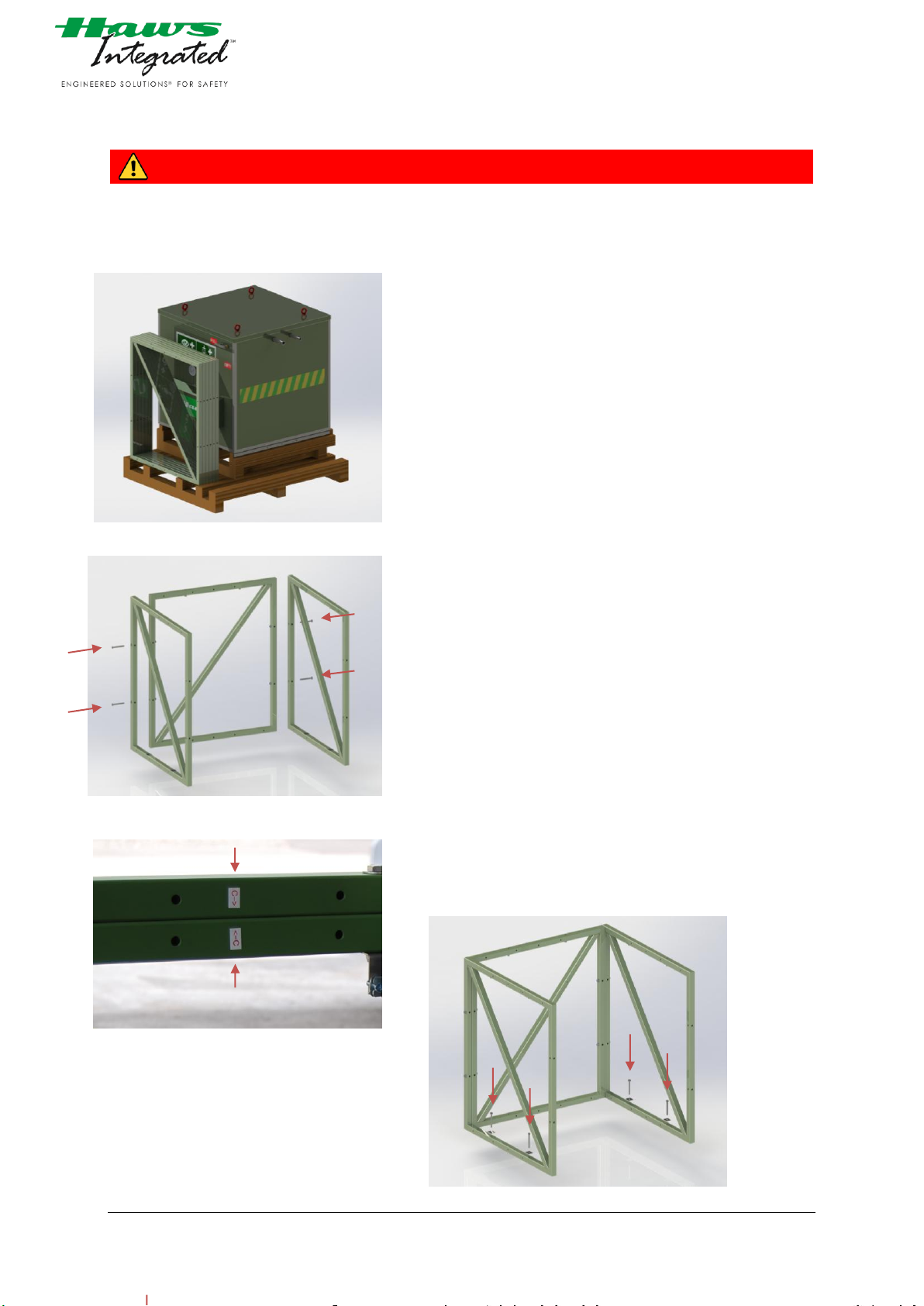
picture 8 tank shower packed
picture 9 Installation
picture 10 markings
picture 11 Installation
9.2 ASSEMBLY INSTRUCTION
DANGER !
Please ensure that all personnel maintain a sufficient safety distance and stay outside the
dangerous area when errecting the safety shower.
1) A forklift capable of lifting 2’000kg should transport the
tank-shower from the truck to the site. The unit should be
lifted centrical and not to high above the ground.
2) The tank-shower might be placed over a sewer drain, the
drain should be able to handle a flow of 100l/min.
3) First, the frame must be installed. Start with three frame
moduls and mount them as shown in picture 9 (4x
M10x100, 8x washers M10, 4x Nut M10).
The markings (arrow with letter, picture 10) on the frame
modules will help you to assemble the frame modules
correctly and pay attention to the alignment of the frame
moduls. Grease the thread of the screws before mounting
the frame.
4) The tank-shower is supplied with brackets to anchor the
frame to the floor or concrete pit. Anchor the tank-shower
with the supplied brackets picture 11. Haws AG
recommends to use M10 screws for anchoring.
4000.12_V1 2014-08-08 Autor: tara
©Haws AG Switzerland Confidential Page 19
Page 20
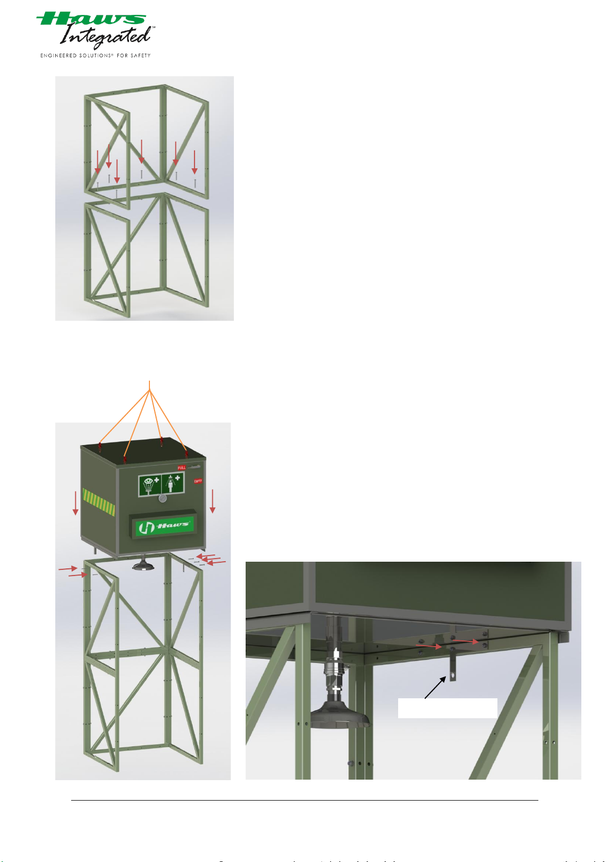
picture 12 Installation
picture 13 Installation
picture 14 Installation
plain bearing holder
5) Mount the other three frame moduls together as shown in
the picture 12 (4x M10x100, 8x washers M10, 4x Nut
M10). Then mount the upper part on the lower part of the
frame (6x M10x100, 12x washers M10, 6x Nut M10) The
markings (arrow with letter) on the frame modules will
help you to assemble the frame modules correctly and pay
attention for their alignment.
6) Put the tank on the frame while using the lifting lugs on
the top of the tank. When the tank is on the frame screw
them together. (5x M8x60, 10 washers M8, 5x Nut M8)
picture 13
Pay attention that the plain bearing holder is also mounted
with the same screws on the right inside. picture 14
4000.12_V1 2014-08-08 Autor: tara
©Haws AG Switzerland Confidential Page 20
Page 21
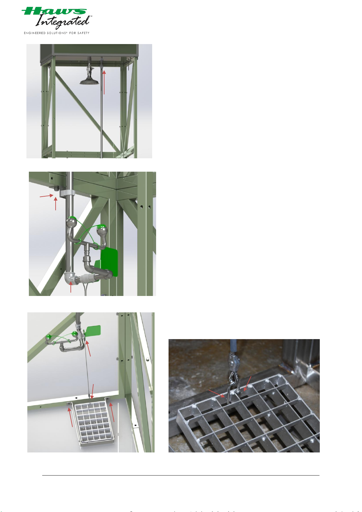
picture 15 Installation
picture 17 Installation
picture 18 Installation
picture 16 Installation
7) Install the ¾” pipe for the eye wash directly under the
tank. picture 15
8) Mount the eye wash at the other end of the ¾” pipe. Pay
attention to the alignment of the eye wash. Afterwards
mount the pipe clip with the bracket on the frame as
shown in picture 16 to fix the pipe.
9) The foot treadle should be mounted on the right below.
Attach the rope from the push flag to the foot treadle.
picture 17 and picture 18.
4000.12_V1 2014-08-08 Autor: tara
©Haws AG Switzerland Confidential Page 21
Page 22
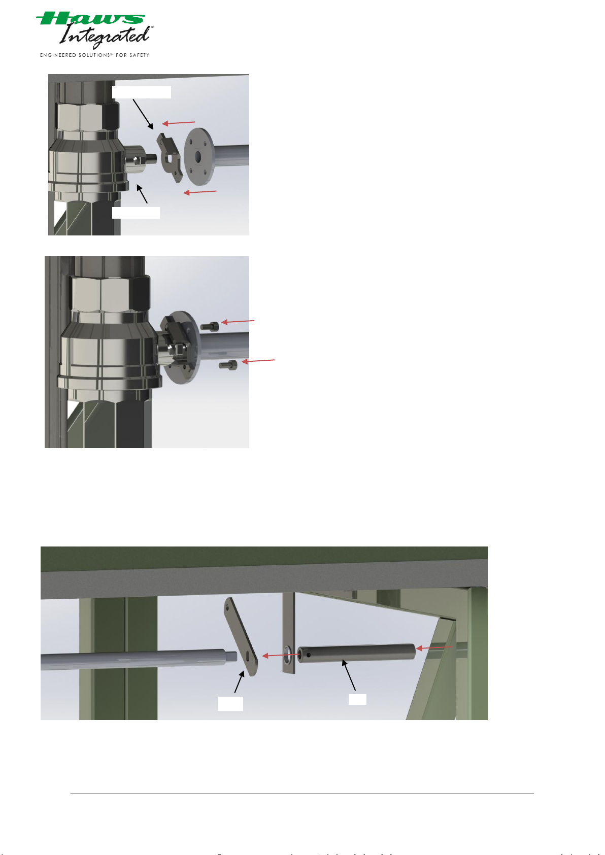
picture 19 Installation
picture 20 Installation
picture 21 Installation
stop bracket
Ball valve
rod
lever
10) Mount the stop bracket on the ball valve. Pay attention to
the alignment of the stop bracket.
Put a little bit of Loctite (screw securing) on the thread and
screw the rod as far as possible in and make sure that the
holes are matching. picture 19
11) The bracket and the rod will be fixed together with the two
screws. (2x M4x10) picture 20
12) Mount the lever on the rod and put a little amount of
Loctite on the thread and screw the short rod in as far as
possible and make sure that the hole is perpendicular to
the surface. picture 21
4000.12_V1 2014-08-08 Autor: tara
©Haws AG Switzerland Confidential Page 22
Page 23
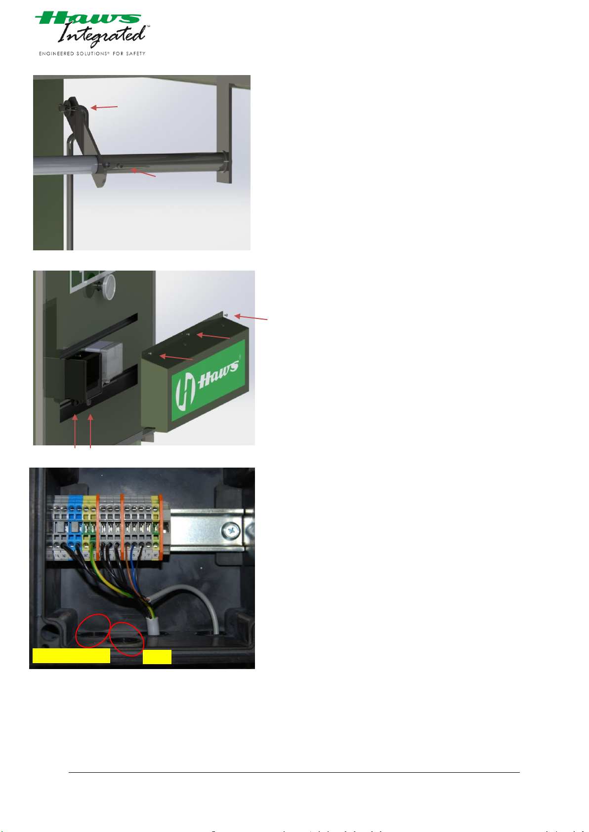
picture 22 Installation
picture 24 Electrical installation
picture 23 Electrical installation
Alarm
Electrical supply
13) Fasten the grub screws (2x M5x6) and mount the pullrod
as shown in picture 22.
14) The electrical supply connection must be made to the
disconnect switch in the junction box.(L,N,PE) The unit
requires 230 V single phase, 13A time-lag service.
Install the cable for the alarm to the junction box. (4,5,6)
picture 23 and picture 24. Detailed information you’ll find
on the electrical wiring diagram picture 7.
4000.12_V1 2014-08-08 Autor: tara
©Haws AG Switzerland Confidential Page 23
Page 24

15) In case the water supply line will be directly connected to
the unit it has first to run for few minutes without
connection. This will help to eliminate any debris.
16) Once all water and power connections are made you may
fill-up the tank.
17) Test the function of the valves and inspect the plumbing
for leaks. During transit, some plumbing may have vibrated
loose, allowing water to leak from the threads. Once
plumbing has been checked fill-up the tank again.
NOTICE !
Upon erecting at low temperatures (below freezing point) it is recommended to connect the electronical
equipement first. This prevents damage to the tank-shower unit by freezing.
In addition ensure that the thermostat is turned on and connected
4000.12_V1 2014-08-08 Autor: tara
©Haws AG Switzerland Confidential Page 24
Page 25

9.3 CONNECTION LIST
Electrical connection at booth 230 V, 2-Wire + Ground
Water Supply connection 1 ¼" BSP male
Water Additive Inlet 1" elbow
NOTICE !
Maximum pressure of water supply must not exceed 6bar
Maximum utilities consumption rates for this unit are as follows:
Electrical Power 230VAC, 13 Amps time-lag (Power Consumption of 1.2kW)
Water Body shower
Approx. 60l/min
(decreasing water flow and pressure during use)
Eye wash
Approx. 6l/min
(decreasing water flow and pressure during use)
_____________________________________________
9.4 CHECKLIST AFTER ERRECTING / YEARLY CHECKUP
leak tightness requirements :
- Valves of eye and bodyshower are closed
- Tank is filled up
Check all supply-lines of tightness
If water leakage appears renew the sealing of concerned
fitting
operation of valves open the valves by pushing the push flag and pulling the pull
rod down to end position
valves shall stay open without any further action
determining of spraying pattern check if spraypattern of the body shower has a diameter of
minimum 50.8cm on a hight of 152.4cm.
determining of beam hight of eye wash The jet of water supplied by the nozzles shall spray at a
minimum height of 106mm and may spray at a
maximum height of 203mm both measured from the nozzle
centre, before tipping over or collapsing.
NOTICE !
The dissassembly of the eye wash unit may only be performed by qualified personnel after the
manufacturer/supplier has been consulted and has given his approval.
4000.12_V1 2014-08-08 Autor: tara
©Haws AG Switzerland Confidential Page 25
Page 26
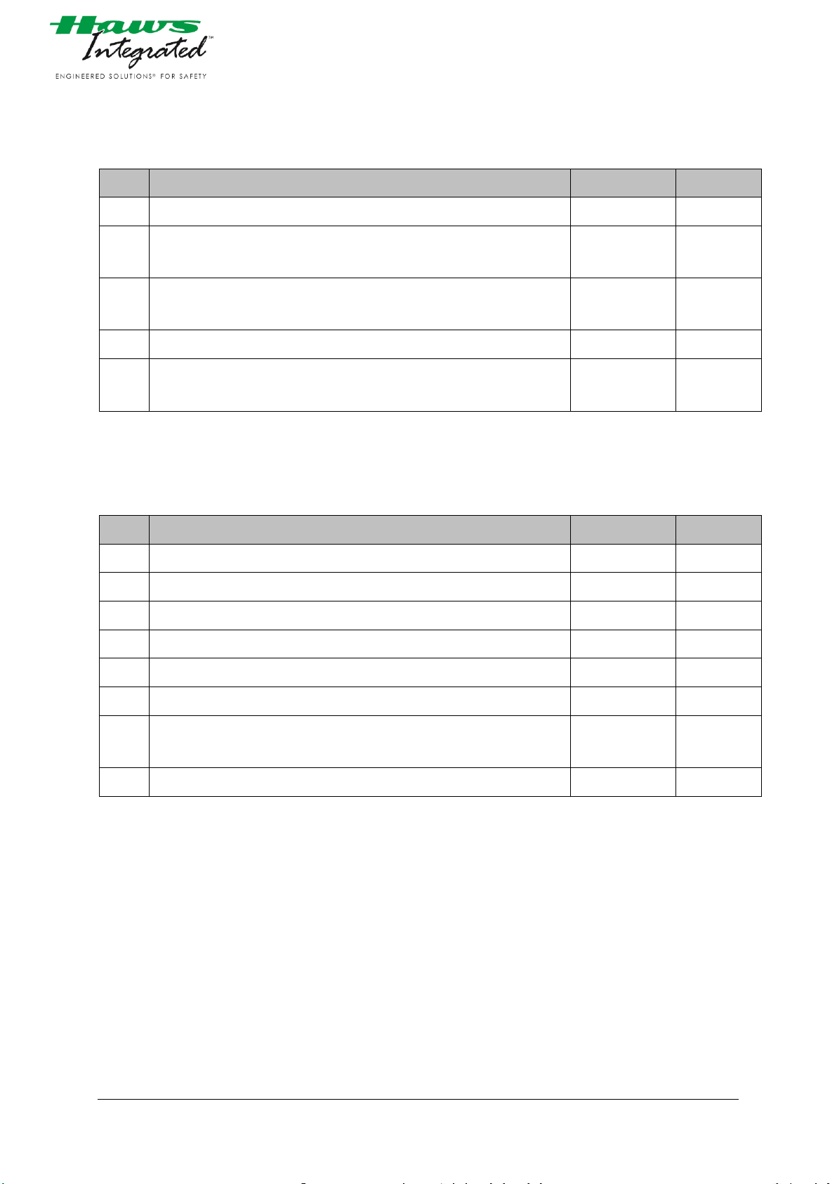
DESCRIPTION
EXECUTED
STATUS
1.
Installing priority see reference relevant project P&IDs.
2.
Review Shower unit assembly for damage/wear.
Repair if necessary.
3.
Confirm connections are made per the relevant Shower assembly GA,
P&ID, and Wiring Diagram.
4.
Fill-up watertank of unit
5.
Switch on power to the unit and note the following:
Thermostat is working
DESCRIPTION
EXECUTED
STATUS
1.
Open safety shower and eyewash valves to initiate flow
1.
Check water distribution
2.
Turn shower or eyewash off
3.
Turn thermostat high
4.
Check if heating cable getting hot
5.
Adjust temperature on thermostat back to normal condition
6.
Confirm that all valves are left in standby position and that polar
shower booth is ready for operation
7.
Fill-up watertank of unit
_____________________________________________
9.4.1 PRE-COMMISSIONING PROCEDURE
9.4.2 COMMISSIONING PROCEDURE
Tag:________________________
Commissioning completed and accepted:
Sign: ___________ ____________
Date: ___________ ____________
4000.12_V1 2014-08-08 Autor: tara
©Haws AG Switzerland Confidential Page 26
Page 27

9.5 BRIEFING OF PERSONNEL AND ORGANISATION OF MAINTENANCE
Personnel requirements • Facility Security Officer or similar officially named person
Training of Personnel • after the safety shower has been properly installed
carry out a training of personnel.
Minimum content of the briefing:
- operation of body shower and eye washer
(turn on / off)
- Tripping hazards and barriers on your way to the safety
shower.
Ensure that new personnel will be trained
Organisation of maintenance • please ensure that the maintenance of the Emergency
Safety Shower is done in accordance with the instructions
staded on this Documentation.
4000.12_V1 2014-08-08 Autor: tara
©Haws AG Switzerland Confidential Page 27
Page 28

10 SITE ACCEPTANCE PROTOCOL
This Site Acceptance Protocol is a written declaration signed by the Manufacturer and the Customer which
confirms that the Equipment defined hereunder is ready to use in accordance with the Technical Conditions of
our contract No. ________________(hereinafter “Contract”) with:
Customer: __________________________ Address: __________________________________
Country: ___________________________ Equipment Designation: ______________________
Short Description of Equipment: __________________________________________________
Manufacturer informs Customer officially that the formal testing of Equipment has been conducted by the
Manufacturer on ___/___/___ (DD/MM/YY) on the following location: ____________ and that the Equipment
conforms to the Technical Conditions and is ready to use by the Customer.
Signed at_____________ on the____________Day of____________________________
FOR THE Customer
Name: _________________________________________
Function: _______________________________________
FOR THE Manufacturer
Name: _________________________________________
Function: _______________________________________
4000.12_V1 2014-08-08 Autor: tara
©Haws AG Switzerland Confidential Page 28
Page 29

ANNEX: SAT PROTOCOL
Name:
Function:
E-Mail
Name:
Function:
E-Mail
Attendees during Site Acceptance Test:
Customer:
Manufacturer:
Factory Acceptance notes:
FOR THE Customer
Name: _________________________________________
Function: _______________________________________
FOR THE Manufacturer
Name: _________________________________________
Function: _______________________________________
4000.12_V1 2014-08-08 Autor: tara
©Haws AG Switzerland Confidential Page 29
Page 30
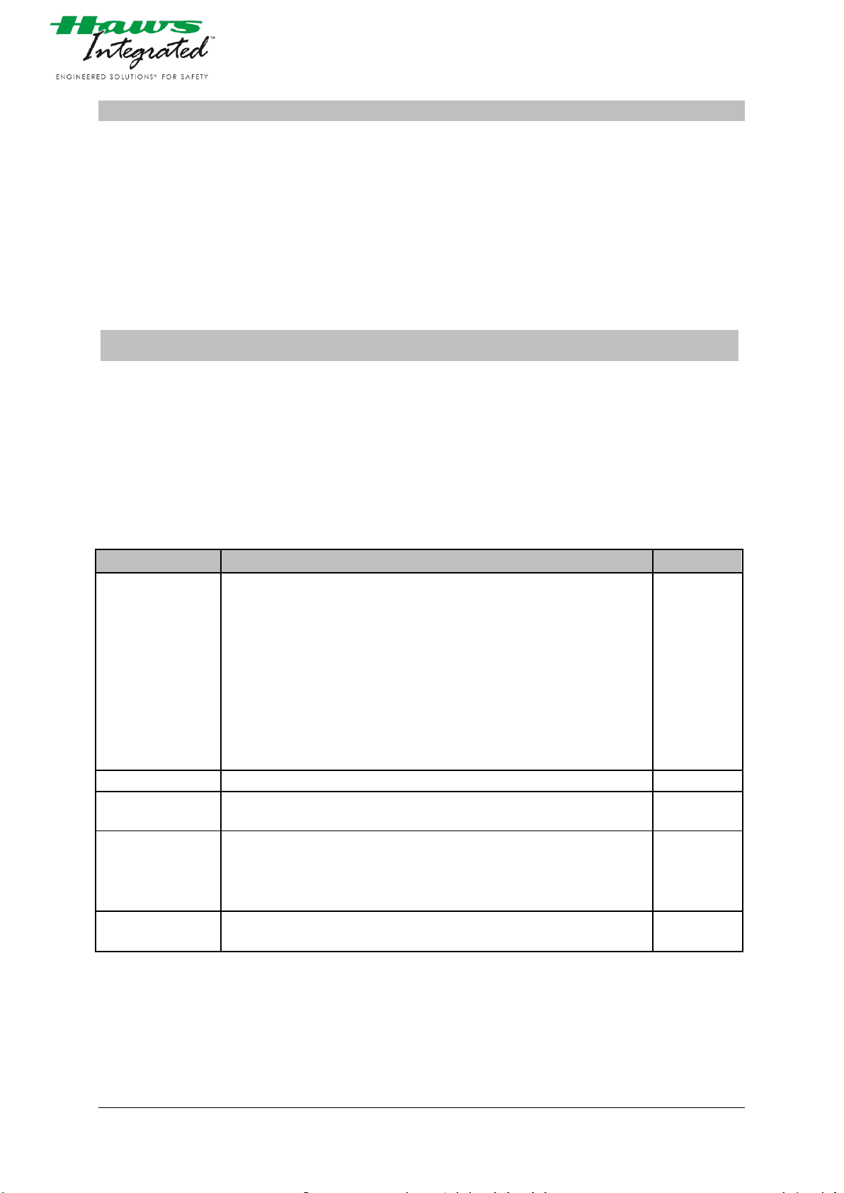
TIME INTERVALLS
ACTION
PERSONNEL
weekly
carry out a general visual inspection:
- mechanical damage?
- leakages at the junction points?
For the function control of the bodyshower and eyewash unit:
- Let the water run freely until the tank is empty. Then fill tank
with fresh drinkable or similar quality of water
- check if spraypattern of the body shower and eye wash:
does it become calcified ?
In case of complaints:
- Arrange remedial action
Complete the maintenance report
E
as necessary
Elimination of complaints
SF
yearly
carry out the checklist after errection/yearly checklist (Page 25)
Complete the maintenance report
SF
yearly
Check if safety shower is according to current applicable laws,
regulations and standards
If not: arrange remedial action
Complete the maintenance report
SB
All two years
Replace all filter in watersupply
Complete the maintenance report
SF
11 MAINTENANCE
Personnel requirements • Only people who are trained and familiarised may
maintain the emergency safety shower. (E)
For inspection of current applicable laws, regulations and
standards:
Facility Security Officer or similar officially named person
(SB)
Other works:
Sanitary specialist (SF)
NOTICE !
The dissassembly of the eye wash unit may only be performed by qualified personnel after the
manufacturer/supplier has been consulted and has given his approval.
_____________________________________________
11.1 MAINTENANCE SCHEDULE
4000.12_V1 2014-08-08 Autor: tara
©Haws AG Switzerland Confidential Page 30
Page 31

11.2 MAINTENANCE REPORT
Use following Page as a master copy.
4000.12_V1 2014-08-08 Autor: tara
©Haws AG Switzerland Confidential Page 31
Page 32
WK
DATE
STATE
SIGN.
WK
DATE
STATE
SIGN.
1
27 2 28 3 29
4
30 5 31
6
32 7 33 8 34
9
35
10
36
11
37
12
38
13
39
14
40
15
41
16
42
17
43
18
44
19
45
20
46
21
47
22
48
23
49
24
50
25
51
26
52
DATE
SIGNATURE
DATE
SIGNATURE
DATE
SIGNATURE
Maintenance report of the Year 20.....
Safetyshower model Haws 4000 Tank shower
Facility: …………………………………………..
Weekly check
yearly check
Check if according to applicable laws, regulations and standards
Two years check
4000.12_V1 2014-08-08 Autor: tara
©Haws AG Switzerland Confidential Page 32
Page 33
11.3 TROUBLE SHOOTING
PROBLEM
CHECKLIST
No flow.
Water tank might be empty, check water level
indicator at the front side of Tank shower. Check the
main shut off valve on Tank showers with connecton
to the water supply line.
Insufficient water flow on eyewash, however, shower is
sufficient.
Clogged flow controls. Remove eyewash heads.
Clean or replace flow control inside of head
assembly.
Remove and clean the eye wash inline strainer,
accessible by the left sided service door.
Eyewash stream does not meet desired eye level.
Possible blocked strainer or eye wash heads, see
above solution. Possible non-leveled eye wash
assembly. Eye wash nozzles should be at equal
heights.
Insufficient water flow at the showerhead,
however, eyewash is sufficient.
Probable clogging of the flow control inside
showerhead. Unscrew shower head and clean the
rubber flow control.
Water temperature drops below the preadjusted
temperature.
- Check that the wiring is correctly and safely
connected in accordance with the wiring
diagram.
- Check the fuses of the power supply line, and
also check the wiring to the shower regarding
damages.
If there are any questions that cannot be answered here, please consult Haws Integrated.
4000.12_V1 2014-08-08 Autor: tara
©Haws AG Switzerland Confidential Page 33
Page 34

12 MANUALS / DRAWINGS & CERTIFICATES OF COMPONENTS
12.1 HEATING CABLE GM 2X
www.pentairthermal.ch
12.2 END SEAL KIT E-150
www.pentairthermal.ch
12.3 POWER CONNECTION KIT C-150-E
www.pentairthermal.ch
12.4 JUNCTION BOX GIFAS TYPE 3020
www.gifas.ch
12.5 THERMOSTAT RAYSTAT CONTROL 10
www.systectherm.ch
12.6 INDUCTIVE SENSOR IS M12
www.steute.ch
12.7 BIMETAL THERMOMETER Model 52
www.manometer.ch
4000.12_V1 2014-08-08 Autor: tara
©Haws AG Switzerland Confidential Page 34
Page 35
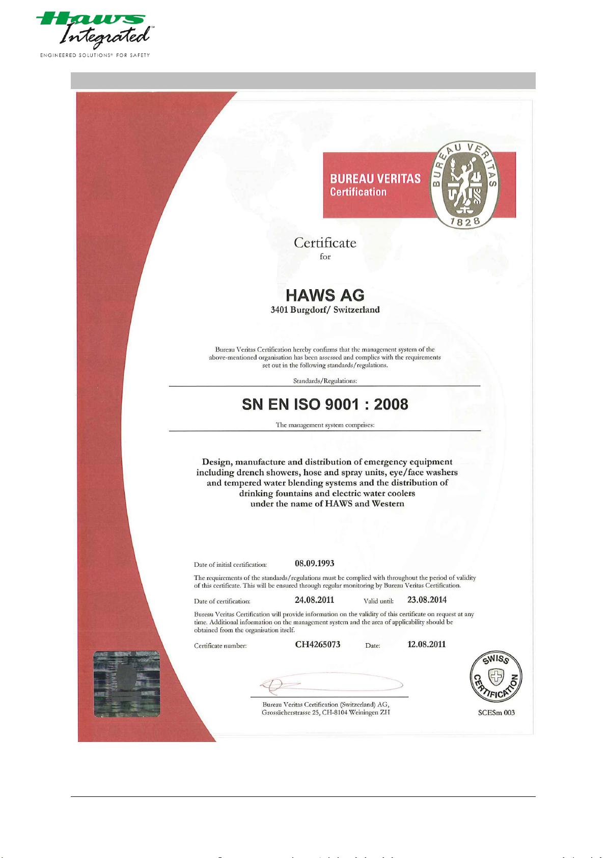
13 CERTIFICATION HAWS
Picture 25 Certificate Haws AG
4000.12_V1 2014-08-08 Autor: tara
©Haws AG Switzerland Confidential Page 35
Page 36
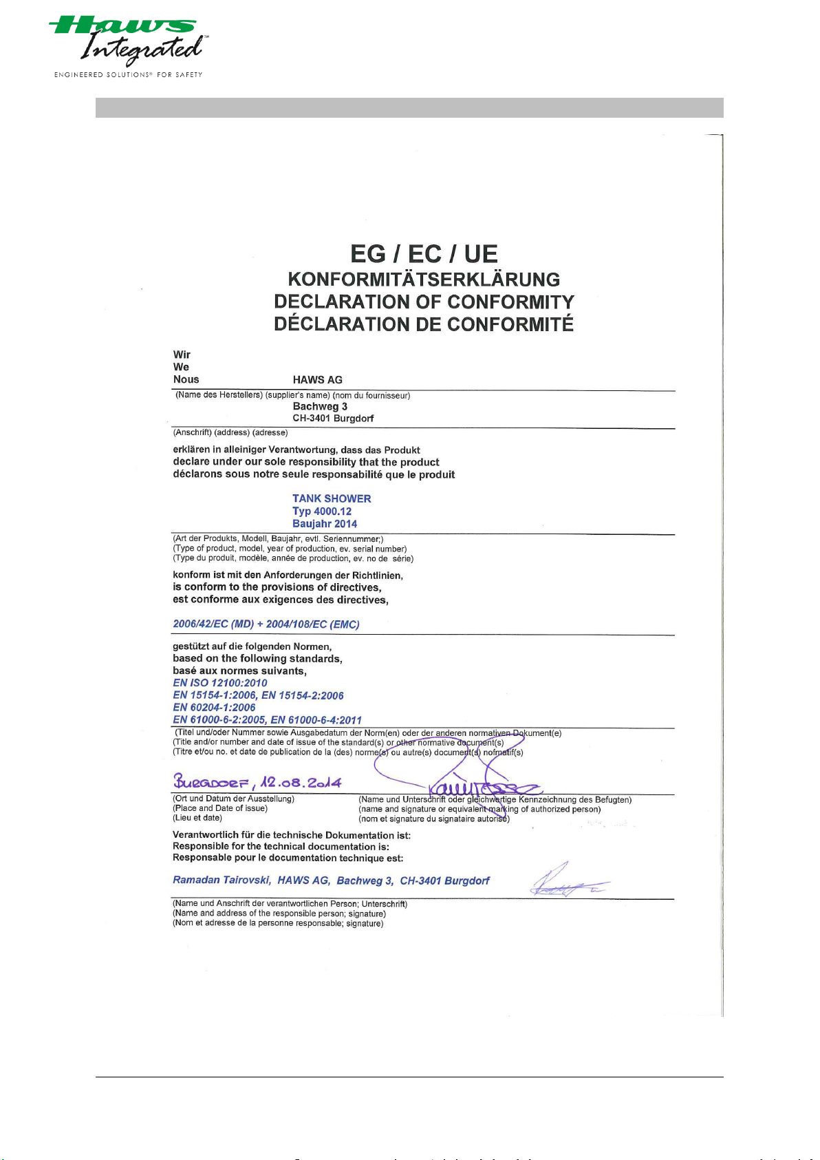
14 DECLARATION OF CONFORMITY HAWS
picture 26 Certificate of Conformity Haws
4000.12_V1 2014-08-08 Autor: tara
©Haws AG Switzerland Confidential Page 36
Page 37

15 LIST OF FIGURES
Picture 1: Cover picture .......................................................................................................................................... 1
Picture 2: Name plate ............................................................................................................................................. 7
Picture 3: Drawing of GA Haws ............................................................................................................................. 10
Picture 4: P&ID Drawing ........................................................................................................................................ 11
Picture 5: controls ................................................................................................................................................. 12
Picture 6: Drawing of spare parts.......................................................................................................................... 13
Picture 7: Wiring diagram ..................................................................................................................................... 17
picture 8 tank shower packed ............................................................................................................................... 19
picture 9 Installation ............................................................................................................................................. 19
picture 10 markings .............................................................................................................................................. 19
picture 11 Installation ........................................................................................................................................... 19
picture 12 Installation ........................................................................................................................................... 20
picture 13 Installation ........................................................................................................................................... 20
picture 14 Installation ........................................................................................................................................... 20
picture 15 Installation ........................................................................................................................................... 21
picture 16 Installation ........................................................................................................................................... 21
picture 17 Installation ........................................................................................................................................... 21
picture 18 Installation ........................................................................................................................................... 21
picture 19 Installation ........................................................................................................................................... 22
picture 20 Installation ........................................................................................................................................... 22
picture 21 Installation ........................................................................................................................................... 22
picture 22 Installation ........................................................................................................................................... 23
picture 24 Electrical installation ............................................................................................................................ 23
picture 23 Electrical installation ............................................................................................................................ 23
Picture 25 Certificate Haws AG ............................................................................................................................. 35
picture 26 Certificate of Conformity Haws ........................................................................................................... 36
4000.12_V1 2014.08.08 Autor: TaRa
©Haws AG Switzerland Confidential Page 37
 Loading...