

Haws 2500.CT User Manual
No. 2077014 (2)
Model 2500.CT
Counter-top Brita® Hydration Station®
OWNER’S MANUAL
Brita® Hydration Station®
Limited Warranty
For complete warranty information, please see page 10 of this owner’s manual.
SHOULD YOU EXPERIENCE DIFFICULTY WITH THE USE OF THIS MODEL, OR
REQUIRE REPLACEMENT PARTS, PLEASE CALL:
TECHNICAL SUPPORT:
1-800-766-5612
HOURS OF OPERATION: MON-THURS 6:00a.m. - 4:00p.m. PT, FRI 6:00a.m. -2:00p.m. PT
RATED SERVICE FLOW: 0.55 GPM (2998L/day) OPERATING TEMP: 35-100°F (1.7-37.8°C)
FILTER CAPACITY: 1500 gallons (5678L) or 12 months
REPLACEMENT CARTRIDGE: Brita® Filter Model 2512
WATER SUPPLY REQUIREMENTS: 88 PSI (5.99 ATM) max supply pressure; cold water only.
Do not use with water that is microbiologically unsafe or of unknown quality without adequate
disinfection before or after the system. Systems certified for cyst reduction may be used on
disinfected waters that may contain filterable cysts.
NOTE: When installing this unit, all pertinent local, state, or federal codes should be adhered to.
This unit is certified for indoor use only.
1455 Kleppe Lane Sparks, NV 89431-6467 (888) 909-4297
website: www.BritaHydrationStation.com
QUICK START REFERENCE (SEE INSTALLATION INSTRUCTIONS FOR FURTHER DETAILS)
© 2013 Haws® Corporation – All Rights Reserved
HAWS® and other trademarks used in these materials are the exclusive property of Haws Corporation.
The BRITA trademark and logo are registered trademarks of Brita LP and used under license by Haws Corporation. All rights
reserved.
6/13 Model 2500.CT Page 1 of 12

BRITA Trademark Usage Guidelines
The Brita trademark and Brita logo (collectively, the “Brita Marks”) are among the most critical elements of
Brita LP’s identity and convey many aspects of our business. The Brita Marks are widely recognized,
positive industry symbols and can be a very effective way to highlight your commitment to the
environment and providing high quality drinking water to your patrons.
The following guidelines apply to customers of the Brita® Hydration Station® water dispensing units and
Brita® filters.
Your purchase of this Brita® product authorizes your company to use and/or display the Brita Marks as
long as:
• You continue to use Brita® filters in the Brita® Hydration Station® water dispensing unit and replace the
Brita® filters as instructed
• You maintain your Brita® product at an appropriate level to provide high quality drinking water to your
patrons
• You do not disparage Brita, LP or Brita® products
• You do not imply a relationship or association with Brita, LP that does not exist
• You adhere to these Trademark Usage Guidelines
Improper use of the Brita Marks may be considered a violation of these Trademark Usage Guidelines,
and Brita, LP reserves all rights to enforce proper use of its trademarks, including but not limited to having
you remove or cover up the Brita Mark on the product.
In the event you have questions about the proper use of the Brita Marks, the Brita® filters or the Brita
Hydration Station® water dispensing unit, please call 888-909-4297 to be connected to a representative of
Haws Corporation. The Brita Marks are registered trademarks of Brita LP and are used under license by
Haws Corporation.
®
Haws Corporation
1455 Kleppe Lane • Sparks, NV 89431
1-888-909-4297
www.Britahydrationstation.com
6/13 Model 2500.CT Page 2 of 12

PARTS LIST: 1 Brita® Hydration Station®, 1 drip tray, 1 filter cartridge, 1 filter head, 1 pressure
regulator with plastic tubing, 1 115VAC power cord.
OPTIONAL ACCESSORIES: Model 2518 1/4" leak-detecting valve.
RECOMMENDED TOOLS: Phillips screwdriver, tubing cutter, adjustable wrench.
REQUIRED PARTS (NOT SUPPLIED): Water supply shutoff valve, 1/4” tubing (for water supply)
SUPPLY LINE: 1/4" tubing. Cold water supply only. Intended for municipal water only.
ELECTRICAL CONNECTIONS: 115VAC, 60HZ, approx. 4.7A.
SIZE: Approximately 17-5/16”H x 14-1/4”W x 19-3/4”D.
Installation
NOTES:
1. Keep the unit upright while moving, operating, or storing it.
2. This unit is certified for indoor use only. Be certain that the installation location for this
unit is level, is not in direct sunlight, is not next to a heat source, and will not freeze. 4” of
clearance around the unit must be maintained to facilitate air circulation.
3. Install this unit within 6’ of its power source. Do not use extension cords or two-pronged
power outlets.
4. Do not use with water that is microbiologically unsafe or unknown quality without
adequate disinfection before or after the system. Systems certified for cyst reduction may
be used on disinfected waters that may contain filterable cysts.
5. For all plastic 1/4" push-in type fitting connections, only connect NSF-61 copper or plastic
tubing. Stainless steel or glass tubing is not recommended. The following assembly
instructions must be followed to ensure a watertight connection:
a. Cut tubing square and clean.
b. Mark 11/16” from end of tube.
c. Push tube into the fitting until it bottoms out.
d. To remove, depress collet and pull tubing out.
Cooler Installation
Step 1: Remove the bright orange Trademark Usage Guidelines Agreement label on the filter (see
below), thereby accepting the guidelines. The label reads as follows:
Removal of this label signifies you or an appropriate owner’s agent will comply with all
BRITA® Trademark Usage Guidelines as well as maintain the unit to the standards as
first installed. Detailed information noting requirements can be found in the Owner’s
Manual.
Screw the filter cartridge into the filter head.
6/13 Model 2500.CT Page 3 of 12
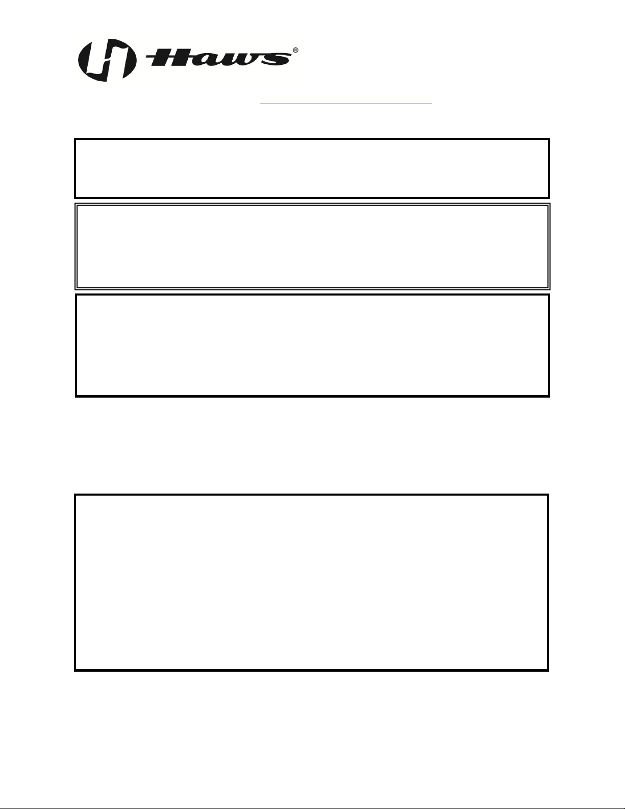
Step 2: Remove the top lid of
the cooler. Unscrew
the 3 Phillips screws
that hold down the
internal lid and lift it
out of place. This will
expose the filter area.
Step 3: Locate the tubing
running into the float
valve on the cooler
tank (see diagram).
There are several
inches of extra length
on this tubing down in
the filter area; without
disconnecting either
end, pull this extra
length out and cut it
squarely approximately at the midpoint.
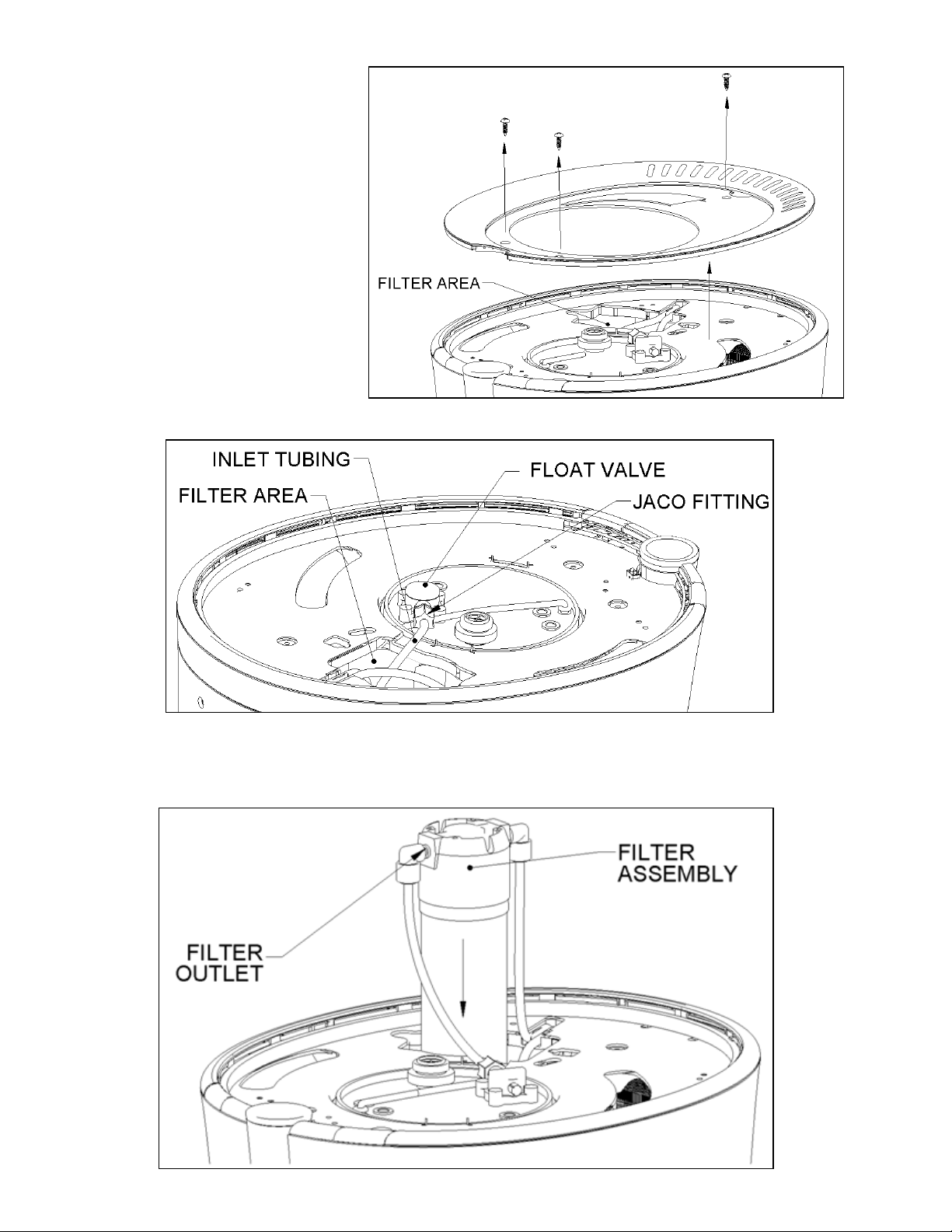
Step 4: Lower the filter assembly partway into the filter area. Connect the newly-cut length of tubing
running from the float valve into the filter outlet (ports are labeled). Connect the other cut
length of tubing into the filter inlet. Lower the filter assembly completely into the cooler,
taking care not to kink the tubing.
6/13 Model 2500.CT Page 4 of 12
 Loading...