

Page 1
INSTALLATION GUIDE
1455 Kleppe Lane Sparks, NV 89431-6467 (888) 909-4297
website: www.Britahydrationstation.com
Brita
NOTE: A Class A ground-fault circuit interrupter
(GFCI) shall be installed in the branch-circuit
supplying power to this unit.
SHOULD YOU EXPERIENCE DIFFICULTY WITH THE INSTALLATION OF THIS
MODEL, OR REQUIRE REPLACEMENT PARTS, PLEASE CALL:
HOURS OF OPERATION: MON-THURS 7:00a.m. - 4:00p.m PT, FRI 7:00a.m.- 1:00p.m. PT
®
Hydration Station
TECHNICAL SUPPORT:
Model 2000SMS
TM
with Lifecycle Control
CAUTION! Prior to making any electrical
connections, verify with a voltmeter that power
from the service panel is off.
1-800-766-5612
No. 2077011 (3)
QUICK START REFERENCE
PARTS LIST: 1 Brita® Hydration StationTM, 1 filter cartridge, 1 plastic drain basin, 1 hex key, 1
grommet.
RECOMMENDED TOOLS: Phillips screwdrivers, level.
REQUIRED PARTS (NOT SUPPLIED): 1/2” screwdriver stop, 3/8” tubing (to be used for water
supply inlet), 6 1/8” x 3” zinc-plated steel toggle bolts, 6 zinc-plated steel 1/8” fender washers.
PRODUCT INSTALLATION: When installing this product, local, state or federal codes should be
adhered to. This unit is certified for indoor use only.
SUPPLY LINE: Minimum recommended line size is 1/2" IPS with 30-90 PSI (2-6 ATM) flowing
pressure; supply water is to be cold water supply. Intended for municipal water only.
PLUMBING CONNECTIONS: Inlet is 3/8” O.D. push-in type fitting. If a waste is desired, the Haws
6470 retrofit 1-1/4” O.D. waste kit may be used.
ELECTRICAL CONNECTIONS: 115VAC, 60HZ, approx. 0.14A. Unit is equipped with a standard
115VAC plug.
RATED SERVICE FLOW: 0.5 GPM (2725L/day)
OPERATING TEMPERATURE: 35–100
OPERATING PRESSURE: 30-90 PSI
FILTER CAPACITY: 2500 gallons (9464L) or 1 year
REPLACEMENT FILTER CARTRIDGE: Brita® Electronic Lifecycle Control Filter Model 6429
© 2014 Haws
HAWS
The BRITA trademark and logo are registered trademarks of Brita, LP and used under license by Haws Corporation. All rights
reserved.
®
Corporation – All Rights Reserved
®
and other trademarks used in these materials are the exclusive property of Haws Corporation.
°
F (1.7–37.8°C)
3/14 Model 2000SMS Page 1 of 5
Page 2
INSTALLATION PROCEDURE
WARNING: Make certain power is disconnected before installation to reduce risk of electrical
shock.
WARNING: Filter is not intended to withstand operating pressures greater than 100 PSI. If inlet
pressure is greater than this, filter must be protected with a pressure regulator.
NOTES:
1. This unit is certified for indoor use only.
2. For all plastic push-in type fitting connections, only connect NSF-61 copper or plastic
tubing. Stainless steel or glass tubing is not recommended. The following assembly
instructions must be followed to ensure a watertight connection:
a. Cut tubing square and clean.
b. Mark from end of tube the length of insertion (See table below).
c. Push tube into the fitting until it bottoms out.
d. o remove, depress collet and pull tubing out.
Tube Sizes O.D. Tolerance Insertion Depth
1/4” ±.005” 11/16”
3/8” ±.005” 3/4”
1/2” ±.005” 7/8”
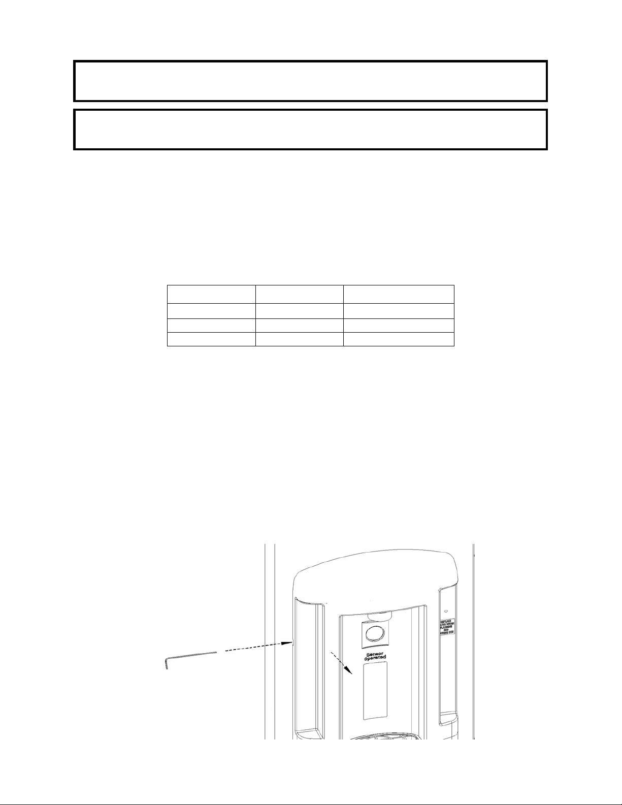
Step 1: To open the unit, slide the supplied hex key into the notch in the left-hand side of the hinged
Take care not to damage the stainless steel panel or the spring latc h in this process.
2. Use NSF-61 approved pipe joint sealant on all threaded water connections.
3. Do not use with water that is microbiologically unsafe or unknown quality without
adequate disinfection before or after the system. Systems certified for cyst reduction
may be used on disinfected waters that may contain filterable cysts.
4. Use the cardboard inserts from the box to support the unit while preparing for
installation by placing unit face down on inserts.
5. There is an opening in the bottom of the unit to accommodate a plumbed waste. If a
plumbed waste is desired, the Haws model 6470 retrofit kit may be used.
upper plastic panel and press the key firmly in that same direction. This will disengage the
internal spring latch. Simultaneously pull open the hinged panel (see Step 1 Diagram).
Step 1 Diagram
Step 1 Diagram
3/14 Model 2000SMS Page 2 of 5
Page 3

Step 2: Remove the 4 mounting screws on the outside
of the Hydration Station with a Phillips
screwdriver (see Step 2 Diagram) and remove
the mounting bracket from the Hydration
Station.
Step 2 Diagram
Step 3 Diagram
Step 3:
Remove the drain basin, drain grate, and filter cartridge from the small box inside the main shipping
carton. Install the drain basin with grate into the front of the unit (see Step 3 Diagram), pushing it straight
in until the snap latches are fully engaged.
Step 4: Thoroughly read Trademark Usage Guidelines (TUG) in O wner’s Manual on
page 2 prior to removal of TUG label on filter cartridge (see Step 4 Diagram A).
Removal of filter label constitutes approval of and compliance with TUG. Firmly
screw the filter cartridge into the filter head (see Step 4 Diagram B). NOTE: the Hydration
Station will work only if a filter cartridge is installed and its wiring is plugged in (see Step 7).
Step 4 Diagram A
Step 4 Diagram B (Back View)
3/14 Model 2000SMS Page 3 of 5
Page 4

Step 5: The Hydration Station is supplied with a power cord. If desired, the power cord may be
g
removed and the unit may be wired through one of the extra holes in the mounting bracket.
Install a supply line through the bottom as shown in Steps 5 & 6 Diagram by removing the
plug from the port and installing the supplied grommet – for use with 3/8” tubing. If desired,
one of the extra ports in the mounting bracket may be used for the supply inlet instead.
Connect the supply line with a screwdriver stop (not supplied).
Double-check supply and electrical locations.
NOTE: When installing this unit, all pertinent local, state, or federal codes should be adhered
to.
Step 6: Secure the detached mounting bracket to the wall; a number of mounting holes are provided
to fasten the bracket direct to the wall (see Step 5 & 6 Diagram for mounting hole pattern or
use the mounting bracket itself as a template).
Note that the Hydration Station weighs approximately 30 pounds. As such, attach the
mounting bracket using six 1/8” x 3” zinc-plated steel toggle bolts (not supplied) in
conjunction with six appropriately-sized zinc-plated steel 1/8” fender washers (not supplied).
Use a level to verify horizontal and vertical frame mounting.
Steps5 & 6Dia
ram
3/14 Model 2000SMS Page 4 of 5
Page 5

Step 7: Place the Hydration Station onto its
mounting bracket and run 3/8” tubing (not
supplied) between the screwdriver stop (installed
in Step 5)and the Hydration Station’s supply inlet
elbow in the filter head (it may help to temporarily
remove the filter cartridge – see Step 7 Diagram).
Connect the wiring coming off of the filter cartridge
to the wiring coming out of the circuit board enclosure
(see Step 7 Diagram).
Step 8: Replace the mounting screws removed
in Step 2 (see Step 2 Diagram for
details).
Provide AC power to unit.
Step 7 Diagram (Back View)
Step 9: Activate the Hydration Station by placing a bottle or cup in front of
the sensor (see Step 9 Diagram A). If water does not dispense,
see the Troubleshooting Guide in the Owner’s Manual.
The pressure regulator may need to be adjusted to better
complement the input pressure at the installation site (see Step 9
Diagram B). To do so, pull out the adjustment knob and rotate as
needed (clockwise from the front of the unit decreases flow); push
knob in when desired flow is achieved. * Flow rate is factory set to
the maximum flow rate for decreased water consumption.
Step 9 Diagram A
Step 9 Diagram B
Step 10: Approximately five gallons of water must be run through the system after the unit is
installed in order to remove the loose carbon particles from the filter cartridge and any air
bubbles from the system (both of these are normal occurrences after a filter change).
Check the system for leaks. Place hex key in a secure location.
3/14 Model 2000SMS Page 5 of 5
 Loading...