

Page 1
No. 0510000047 (4)
Model 1501
Drinking Fountain
INSTALLATION, OPERATION
&
MAINTENANCE INSTRUCTIONS
warrants that this specific product is guaranteed against defective material or
under this warranty shall be discharged by furnishing without charge F.O.B. HAWS
Factory any goods, or part thereof, which shall appear to the Company upon
inspection to be of defective material or not of first class workmanship, provided that
e in writing to Haws within a reasonable period after receipt of the
product. Where claims for defects are made, the defective part or parts shall be
delivered to the Company, prepaid, for inspection. HAWS will not be liable for the
ations or replacements, or for any expense connected therewith
made by the owner or his agents, except upon written authority from HAWS, Sparks,
Nevada. HAWS will not be liable for any damages caused by defective materials or
eplacements, as provided above. Buyer agrees that
HAWS shall not be liable for general, special, or consequential damages claimed to
arise under the contract of sale. The drinking fountain manufactured by HAWS is
aintenance instructions provided are
adhered to. The units also must be used for the purpose for which they were
PROVIDED OR GIVEN BY HAWS.
NOTE TO INSTALLER: Please leave this information with the Maintenance Department.
SHOULD YOU EXPERIENCE DIFFICULTY WITH THE INSTALLATION OF THIS
1455 Kleppe Lane Sparks, NV 89431-6467 (775) 359-4712 Fax (775) 359-7424
HAWS
poor workmanship for a period of one year from date of shipment. HAWS liability
claim is mad
cost of repairs, alter
poor workmanship, except for r
warranted to function if installation and m
intended.
NO OTHER WARRANTIES EXPRESSED OR IMPLIED ARE AUTHORIZED,
MODEL PLEASE CALL:
TECHNICAL SUPPORT: 1-800-766-5612
FOR CUSTOMER SERVICE: 1-888-640-4297
LIMITED WARRANTY
09/17 Model 1501 Page 1 of 5
Page 2
O.D.
1/4”
±.005”
11/16”
3/8”
±.005”
3/4”
1/2”
±.005”
7/8”
RECOMMENDED TOOLS: Hack saw, pipe joint sealant, screwdriver, level, 12" adjustable
wrench, 10" pipe wrench, 5/64” hex key wrench, 9/16”, 1/2”, 7/16” socket wrench or open
end wrench.
LOCATION OF UNIT: The Model 1501 Drinking Fountain is a wheelchair accessible
drinking water facility. The height dimensions shown, meet current ADA requirements.
When installing this unit, local, state or federal codes should be adhered to. If height other
than shown is required, then dimensions must be adjusted accordingly.
SUPPLY LINE: The minimum recommended line size is 1/2“ IPS with 30-90 psi (2-6 ATM)
flowing pressure. Where sediment or mineral content is a problem, an inlet filter is
recommended.
PLUMBING CONNECTIONS: Inle t i s 3 /8” O.D. tubing fitting. Waste trap outlet is 1-1/4”
IPS.
MAINTENANCE: Periodically clean the strainer. Refer to 5874 Series Valve Manual for
more information.
INSTALLATION PROCEDURE
GENERAL NOTES:
1. For all plastic push-in type fitting connections, only connect NSF-61
copper or plastic tubing. Stainless steel or glass tubing is not
recommended. The following assembly instructions must be followed
to ensure a watertight connection:
a. Cut tubing square and clean.
b. Mark from end of tube the length of insertion (See table below).
c. Push tube into the fitting until it bottoms out.
d. To re m ove, depress collet and pull tubing out.
Tube Sizes
Tolerance
Insertion Depth
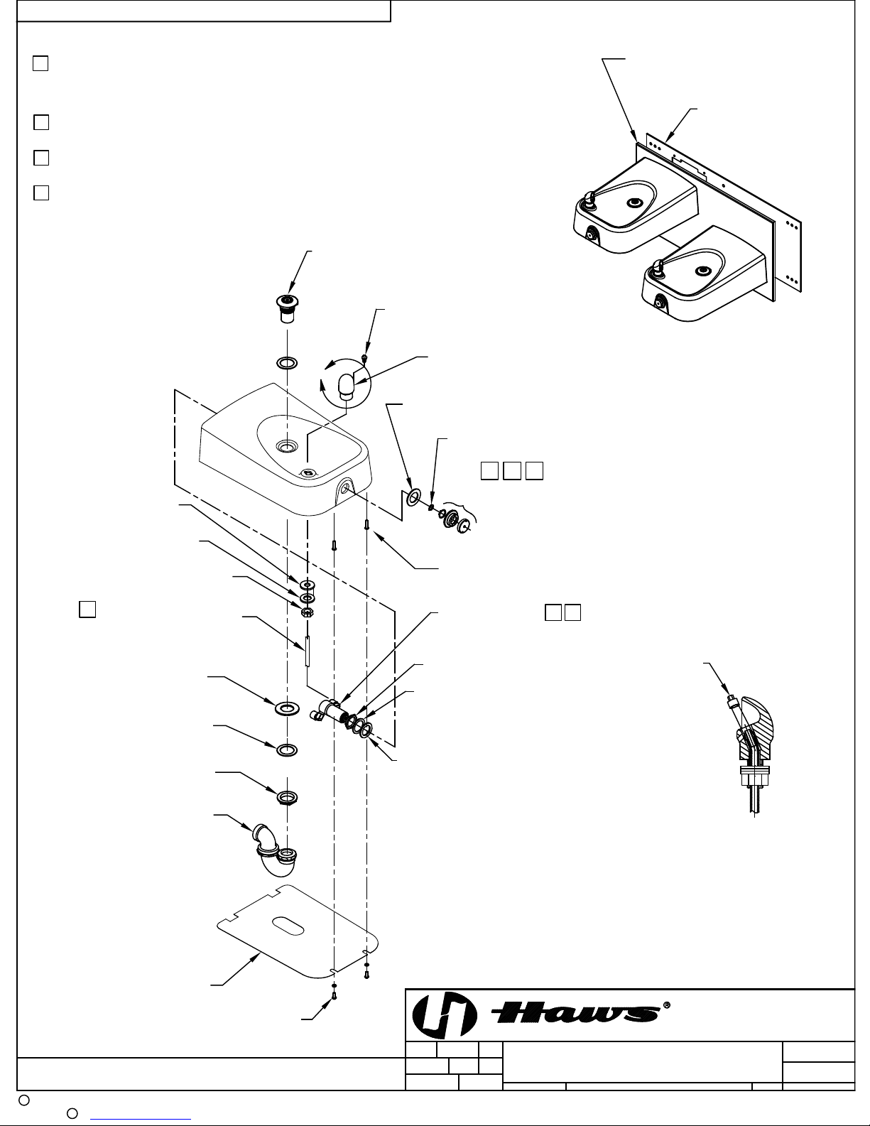
Refer to Installation Drawing for mounting height. For steps below, refer to exploded
view.
STEP 1: Remove hex lock nut and washers from bubbler heads, set aside. Install
bubbler heads through receptor. Install respectively rubber washer, fiber
washer, then nut onto bubbler shank. Securely tighten nut.
STEP 2: Remove push button assembl y from 5874 Series Valves with spanner
wrench provided. Be sure to also remove (chrome plated) ring nut a nd
(chrome plated) washe r from valves. At this point, carefully follow
installation instructions shown on page 5 of 5 of 5874 Series Valve/Push
Button Operation and Maintenance Manual under heading:
“INSTALLATION INSTRUCTIONS FOR 5874 Series Valve W/PBA6”
09/17 Model 1501 Page 2 of 5
Page 3
TROUBLESHOOTING
PROBLEM
REPAIR CHECKLIST
1.
Insufficient bubbler flo w.
1a.
Check that inlet screwdriver stop valve
is in wide-open position.
1b.
Verify minimum 30 psi flow ing supply
pressure.
1c.
Clean strainer. See 5874 Series Valve
Manual.
1d.
Adjust valve to increase flow. Use front
Manual.
INSTALLATION PROCEDURE
STEP 3: Make tubing connections from bubbler to the outlet side of control valve.
Follow instructions for tubing preparation and insertion depths from Step 3.
STEP 4: Place strainer into receptor (using putty), secure in place using a fiber
washer and lock nut.
STEP 5: Mount fountain with back panel to mounting plate using 3/8-16 hardware
(provided).
STEP 6: Flush supply line to clear debris. Connect to a 1/2” NPT supply line and
tighten.
STEP 7: Make certain that fountain is level and well secured to wall. Connect waste
trap to a 1-1/4” IPS waste pipe (to be supplied by customer).
STEP 8: Completely open the screwdriver stop (not supplied) and check for leaks.
STEP 9: Adjust valves for desired flow height. See 5874 Series Valve Manual
(supplied).
STEP 10: Attach bottom plates to fountain using #10-24 hardw are provided.
For more information on Haws products, see our website: www.hawsco.com
© 2017 Haws
HAWS
09/17 Model 1501 Page 3 of 5
®
®
Corporation – All Rights Reserved
and other trademarks used in these materials are the exclusive property of Haws Corporation.
adjust screw or see 5874 Series Valve
Page 4
THIS DOCUMENT IS TRUE AND CORRECT AT TIME OF PUBLICATION. CONTINUED PRODUCT IMPROVEMENTS
MAKE SPECIFICATIONS AND MEASUREMENTS SUBJECT TO CHANGE WITHOUT NOTICE.
NOTES:
1 APPLY ONE DOT OF LOCTITE 222MS THREADLOCKER ON FEMALE
THREADS OF PUSH BUTTON. SEE 5874 SERIES OPERATION AND
MAINTENANCE MANUAL (PAGE 5 OF 5) FOR PROPER APPLICATION
PROCEDURE.
2 5874PBF INCLUDES VRK5874 CARTRIDGE ASSEMBLY AND PBA6 FLANGED
PUSHBUTTON.
3 REFER TO 5874 SERIES OPERATION AND MAINTENANCE MANUAL FOR
INSTALLATION INSTRUCTIONS.
4 CONNECT CLEAR "POLYETHYLENE" TUBING ON FREE FLOW SIDE
(VALVE TO BUBBLER HEAD) ONLY.
STRAINER ASSEMBLY 6453
(NUTS AND WASHERS INCLUDED)
5703M BUBBLER INSERT,
(ASSEMBLED TO BUBBLER)
5703M BUBBLER
A
WASHER 1.98 X 1 1/4-18 UNEF X .10
POLISHED CHROME PLATE
WAVE WASHER
BACK PANEL
PN 0310000132
6715
MOUNTING PLATE
1-1/4 X 1/2 X 1/8
RUBBER WASHER
1-1/4 X 11/16 X 1/8
FIBRE WASHER
3/8 HEX LOCK NUT
4
CLEAR POLY TUBING
(ASSEMBLED TO
2 3/8 X 1 5/16 X 1/8
RUBBER WASHER
2 X 1-25/64 X .050
WASHER
1 3/8-16 LOCK NUT
1-1/4" WASTE TRAP
LOW PROFILE
BUBBLER)
123
PBA6 PUSH BUTTON
ASSEMBLY
2X ANCHOR (PART OF
10-24 HARDWARE)
5874PBF VALVE
(INCLUDES VRK5874
AND PBA6)
LOCK NUT
1-3/4 X 1-5/16 X 3/32
FIBER WASHER
1-13/16 X 1.73 X .12
NEOPRENE WASHER
2
1
DRIVER, NOZZLE
.25 HEX PN
0002082253
(OPTIONAL) FOR
REMOVAL OF
NOZZLE WITH TUBE
VIEW A
ROTATED 90° CCW
DETAIL OF 5703M
PBM1311ADA
PARTS BREAKDOWN
BOTTOM PLATE
2X 10-24 SCREW
ECN:
5218
DATE
08/25/15
DATE
BYECN NO.
CHKD
11/23/17
MODEL(S)
JP
GC
SCALE:
1501
1:1
DRAWING TYPE: SIZE: A
PARTS BREAKDOWN
REVISED PER
5010
DRAWN
WHEN ORDERING PARTS PLEASE SPECIFY MODEL NUMBER.
C
2017
Haws Corporation - All Rights Reserved
HAWS and other trademarks used in these materials are the exclusive property of Haws Corporation.
R
HM
APPROVED
FV
1455 KLEPPE LANE
SPARKS, NEVADA 89431
(775) 359-4712 FAX (775) 359-7424
E-MAIL: [email protected]
WEBSITE: WWW.HAWSCO.COM
PAGE
PART NUMBER
0510000047
REVISION
4
SHEET OF
11
4 of 5
Page 5
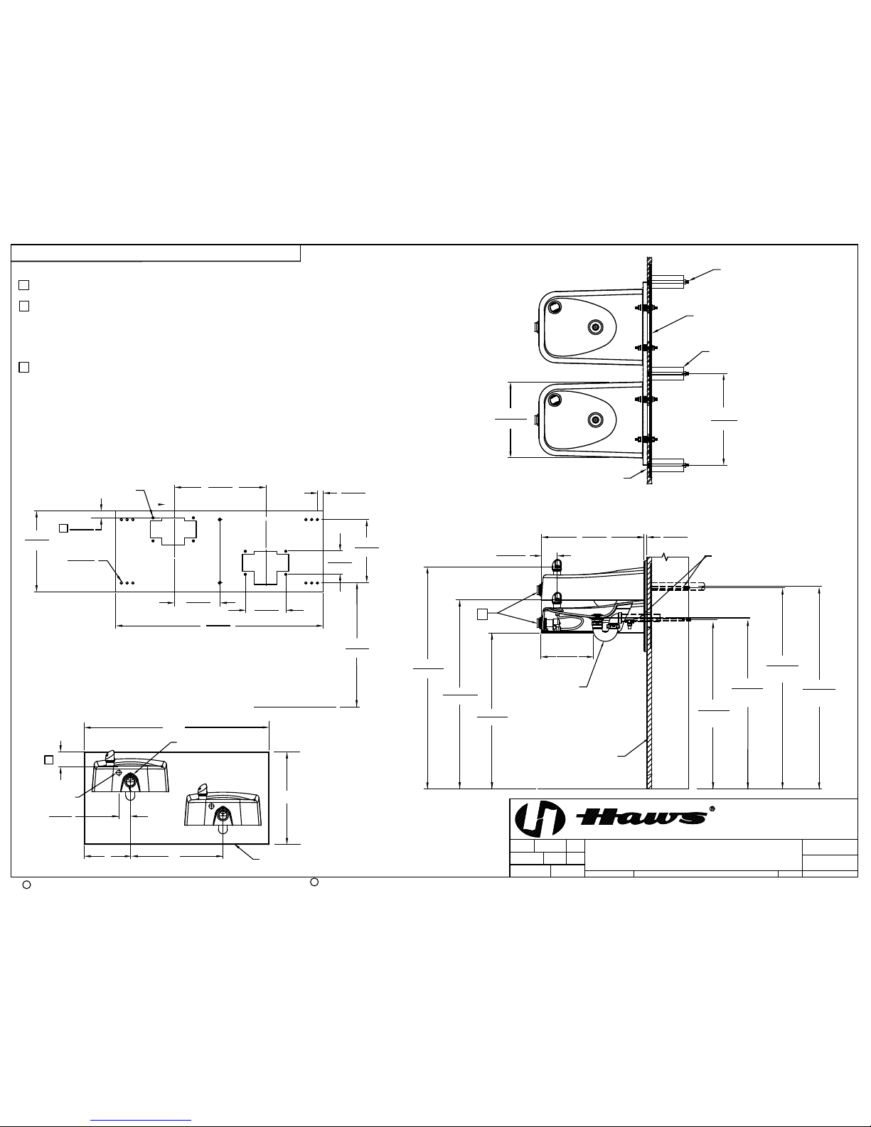
16"
406mm
MOUNTING BOLTS
(NOT SUPPLIED)
WALL STUDS
MOUNTING PLATE
13 1/4"
337mm
2X
(BEHIND FINISH WALL)
2X
NOTES:
1 1 1/4" DIM TO SLOTTED OPENING ON THE MOUNTING PLATE MUST BE ON THE TOP LEFT HAND
SIDE WHEN INSTALLED.
2 2 1/2" DIM TO SLOTTED OPENING ON THE BACKPANEL MUST BE ON TOP LEFT HAND SIDE
WHEN INSTALLED.
3. HOLD ROUGH-IN DIMENSIONS ± 1/4" (6.4MM).
4. WHEN INSTALLING THIS UNIT, LOCAL, STATE, OR FEDERAL CODES SHOULD BE ADHERED TO.
FOR INSTALATION HEIGHTS OTHER THAN SHOWN, DIMENSIONS MARKED (*) MUST BE
ADJUSTED ACCORDINGLY.
5 REFER TO 5874 SERIES OPERATION AND MAINTENANCE MANUAL FOR PUSH BUTTON
AND VALVE INSTALLATION/MAINTENANCE INSTRUCTIONS.
FINISH WALL OVER MOUNTING
PLATE AND BEHIND BACKPANEL.
BE CAREFUL THAT FINISHED WALL
EXTENDS WITHIN THE HAWS
BACKPANEL.
APPROVED:
DRAWN:
PART NUMBER
SCALE:
SHEET OF
REVISION
DRAWING TYPE: SIZE: A
BY:ECN NO.
PAGE
DATE:
DATE:
ECN:
REVISED PER
CHK'D.:
Haws Corporation - All Rights Reserved.
HAWS and other trademarks used in these materials are the exclusive property of Haws Corporation.
C
R
MODEL(S)
1455 KLEPPE LANE
SPARKS, NEVADA 89431
(775) 359-4712 FAX (775) 359-7424
E-MAIL: [email protected]
WEBSITE: WWW.HAWSCO.COM
THIS DOCUMENT IS TRUE AND CORRECT AT TIME OF PUBLICATION. CONTINUED PRODUCT IMPROVEMENTS
MAKE SPECIFICATIONS AND MEASUREMENTS SUBJECT TO CHANGE WITHOUT NOTICE.
HM
08/25/15
4
0510000047.D
1501
1:1
11
FV
11/23/17
5010
GC
5 of 5
INSTALLATION
5218
2017
JP
6715 MOUNTING PLATE
11mm
7/16"
14X Ø
8X 3/8"-16 UNC
178mm
7"
102mm
4"
25mm
8"
203mm
406mm
16"
914mm
36"
660mm
FLOOR LINE
356mm
14"
1
C
L
C
L
SUPPLY
51mm
2"
2X
2 2 1/2"
BACKPANEL
MUST BE INSTALLED BEFORE FINISH WORK.
THIS PLATE IS A STANDARD ITEM ON MODEL 1501ADA.
8"
2X SUPPLY TUBE
2X WASTE PIPE
16"
16"
32"
1 1/4"
32mm
11"
279mm
1"
26"
*38 1/2"
686mm
978mm
*32 3/4"
832mm
*27"
WALL FACE
FLOOR LINE
LOW PROFILE
1 1/4" TRAP
2 3/4"
70mm
18"
457mm
SUPPLY
889mm
*35"
SUPPLY
*29"
737mm
WASTE
746mm
*29 3/8"
*35 3/8"
WASTE
898mm
(NOT SUPPLIED)
SCREWDRIVER STOP
2X 3/8" OD TUBING &
13mm
1/2"
(SUPPLIED)
5
9 1/8"
232 mm
 Loading...