

Page 1
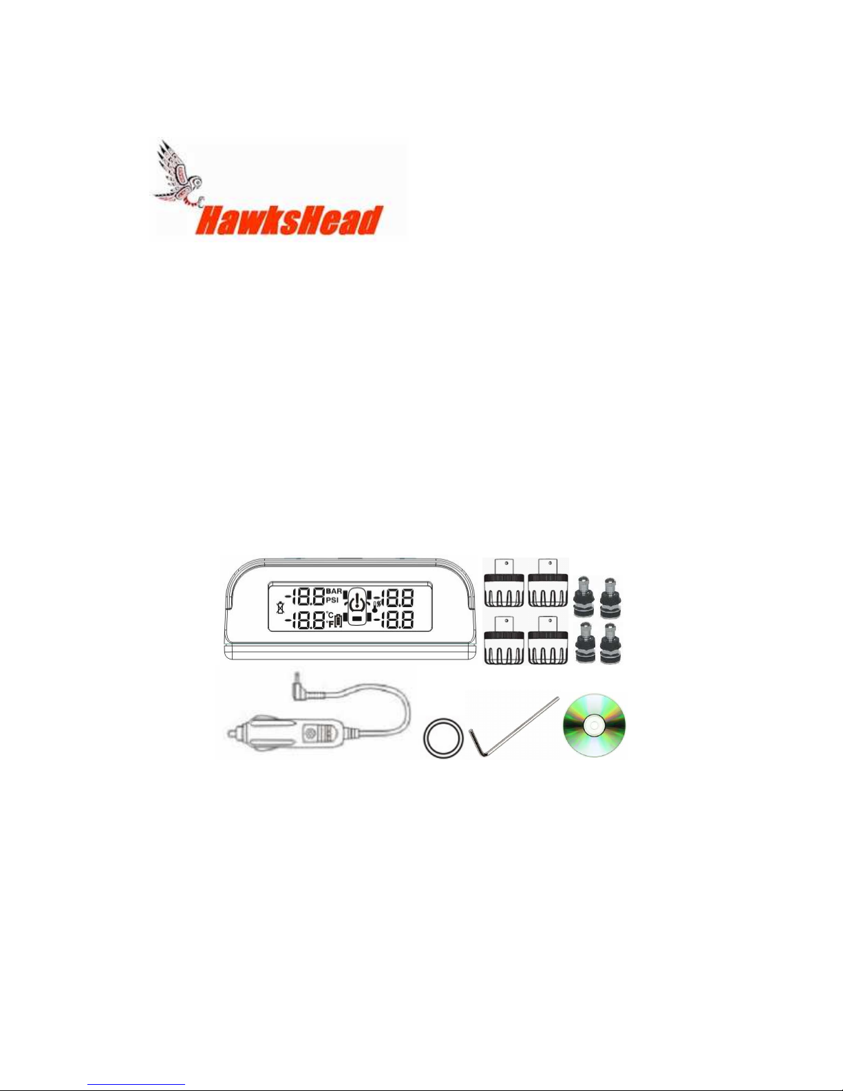
Thank you for your purchase of The HawksHead TRACK MASTER TPMS
System
With ease of installation and a compact data monitor with clear LCD display and
built in rechargeable lithium battery, The Track Master monitor has an automatic
backlight for both day and night use. The monitor can handle up to 5 wheels by
the addition of an extra sensor (purchased separately) beyond our 4 wheel base
system for monitoring a spare tire. Designed for pressures from 16 to 50psi and
temps up to 199 F
High and low pressure warnings along with high temperature warnings can be
set by the user. The monitor gives both visible and audible alerts for High
pressure, Low Pressure, Rapid pressure drop and high temperature. Pressure
and Temperature units can be displayed in PSI, Bar and Temperature in degrees
F & C..
System Components
Sensors Feature
Replaceable CR1632 batteries, Simply fits to valve stem, Water and dirt
resistant, Unique codes.
Monitor Features
Super compact screen, Automatic sleep mode, rechargeable power pack, Auto
backlight
Page 2
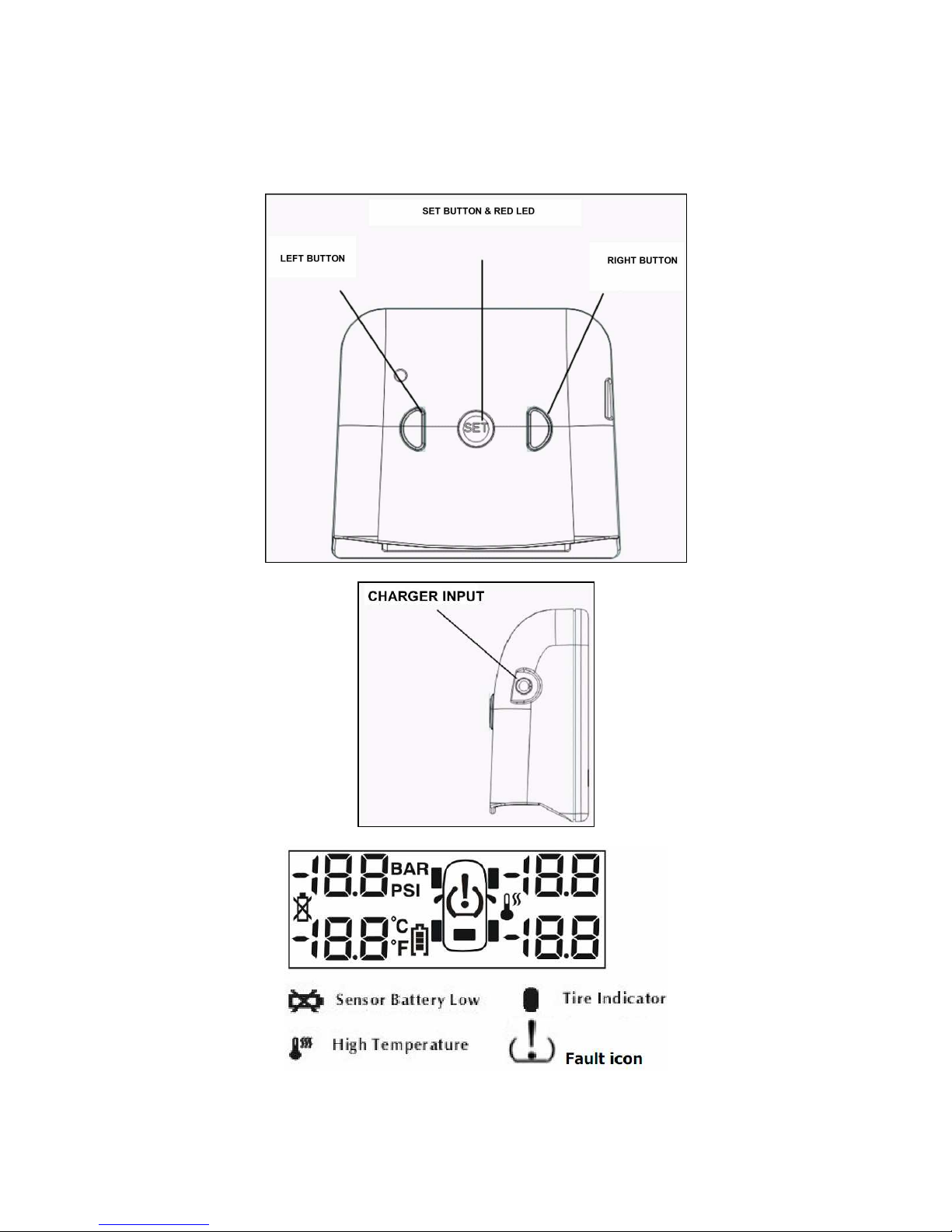
MONITOR BUTTONS & DISPLAY
Page 3
OPERATION & SET UP
Charge the monitor for 6 hours using the charger.
Turning the monitor on or off can be achieved by holding down the LEFT
BUTTON for 5 seconds.
The monitor can be mounted in view of the driver by using the two sided tape
supplied.
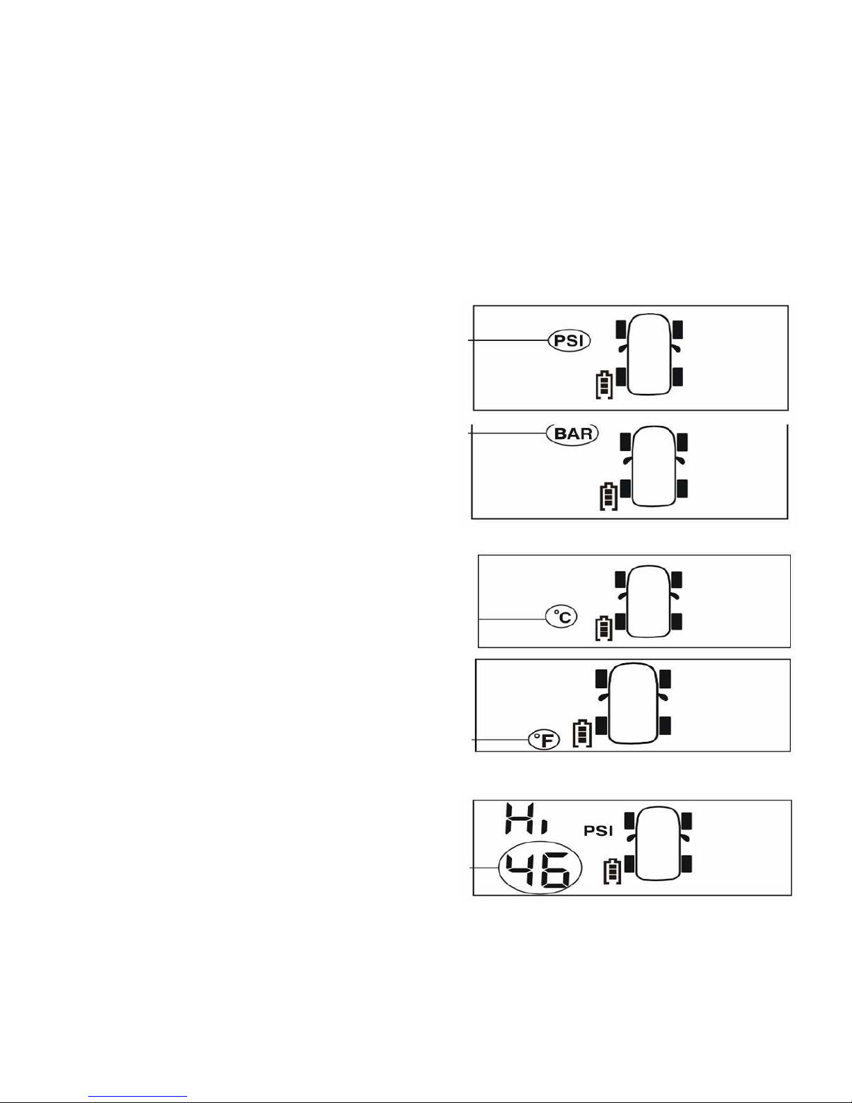
Factory presets are PSI, High Pressure alarm 46 psi, Low pressure alarm 26psi,
Temp unit Degree C, Hi Temp alarm 70 degrees C. To restore factory defaults
turn off the monitor , press the SET BUTTON and turn ON the monitor at the
same time.
Parameter Setting
Turn on the monitor. Press the SET
BUTTON for 3 seconds. It will Beep and
flash the pressure setting . This can be
switched between PSI & BAR by pressing
the LEFT or RIGHT BUTTON
After PSI or BAR has been selected Press
the SET BUTTON again to enter the
Temperature setting mode. It will Beep and
flash the Temperature setting. This can be
switched between C & F by pressing the
LEFT or RIGHT BUTTON
After the Temperature type has been
selected Press the SET BUTTON again to
enter the High Pressure setting mode. It will
Beep and flash the High Pressure alarm
setting. This can be increased or decreased
by pressing the LEFT or RIGHT BUTTON
Page 4
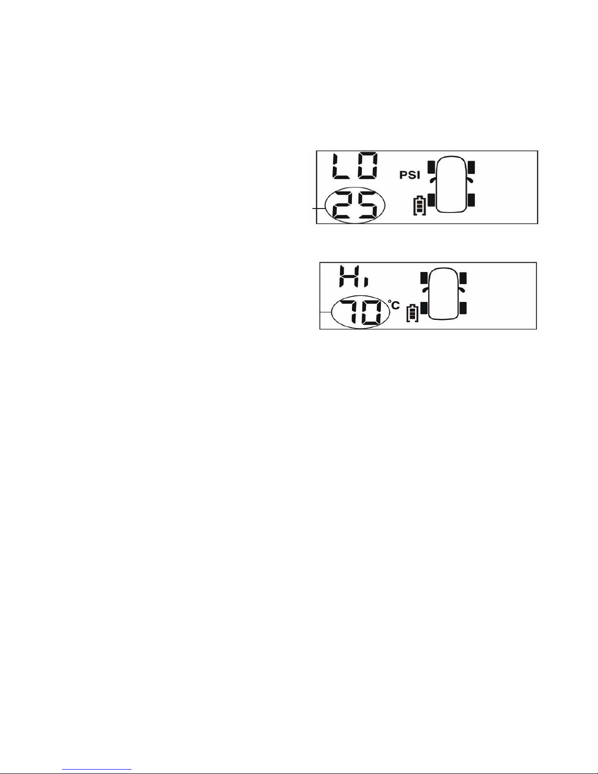
After the High alarm has been set Press
the SET BUTTON again to enter the
Low Pressure setting mode. It will Beep
and flash the Low Pressure alarm
setting. This can be increased or
decreased by pressing the LEFT or
RIGHT BUTTON
After the Low alarm has been set Press
the SET BUTTON again to enter the Hi
Temperature setting mode. It will Beep
and flash the High Temperature alarm
setting. This can be increased or
decreased by pressing the LEFT or
RIGHT BUTTON
Whilst in this mode both the UP and DOWN KEYS can be pressed together to
quit this setting and not save the parameters.
If there is no user operation while in the Set Up mode the monitor will
automatically return to the Standby mode.
Once all parameters have been set hold down the SET BUTTON for 3 Seconds
to get out of the Set Up Mode
SETTING THE VEHICLE TIRE PRESSURES
Using a good quality tire gauge adjust the tire pressures to the desired inflation
as recommended by the vehicle manufacturer. Set these pressures when tires
are cool and out of the sun.
SENSOR INSTALLATION
This should be done one at a time when you read Programming the Sensors
below, do not just screw them all on at once. Remove any existing tire valve caps
and screw the sensor on the valve, ensure the locking screw is backed off
enough to allow the sensor to be screwed on without it rubbing the threads. Hand
tighten the sensor do not use any wrenches or tools to tighten. The locking screw
can be tightened if required as a security measure. Ensure you keep the hex
wrench to remove the locking screws. The sensor simply screws onto the tire
valve (Dill Valve) it is critical that the complete valve be in good condition with no
cracks, be correctly assembled with no wear or side play. Metal valve stems that
are supplied with this system should be used and installed by a tire shop. Use a
small amount of lubrication/anti seize on stem threads ensure none enters the
Sensor or valve. A water/soap solution should be applied to the valve thread
Page 5
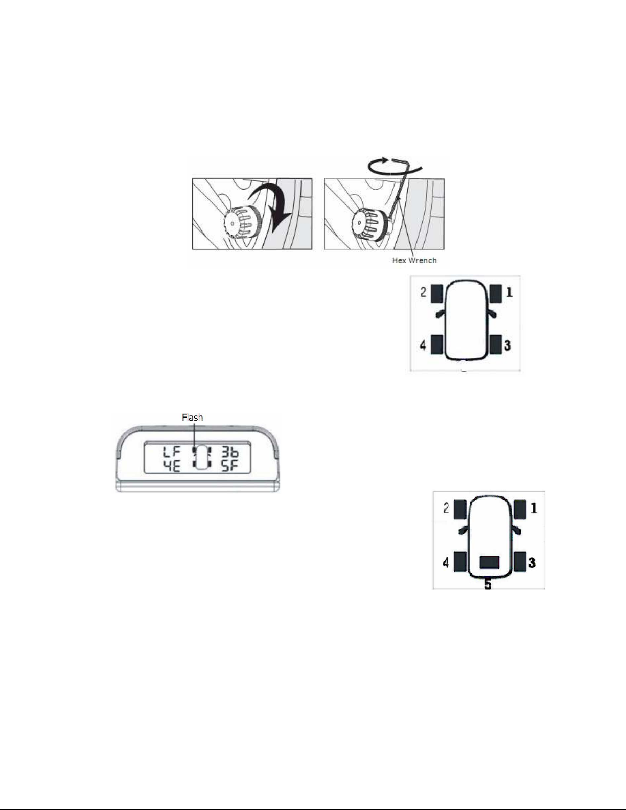
area after installation to ensure there are no air leaks. Most wheels do not need
to be rebalanced after sensor installation. Secure the sensors with their locking
screw if desired.
We have already set up the codes for the 4 sensors
provided and each sensor is marked with the
corresponding tire position.
Should you wish to set up the sensors yourself,
change/add/replace a sensor etc please see below.
Programming the Sensor code if needed.
In the standby mode press the RIGHT BUTTON for 3 seconds. The monitor will
Beep and the relevant Hex code and the wheel position will flash.
Mount the sensor to be aligned on the valve
at the location of the flashing wheel.
The sensor will send the sensor code to the
monitor and the monitor will display the
sensor code associated with the installed
sensor and Beep
Select the other tires by
pressing the LEFT BUTTON and repeat this sequence. The
additional number 5 wheel will also be displayed which can be
used for the spare wheel with the addition of an extra sensor.
By pressing both the LEFT and RIGHT button simultaneously
in this mode the monitor will return to the standby mode
without storing the code.
If there is no operation for a while the monitor will return to the
standby mode
After programming press the SET BUTTON for 3 seconds and release to store
the settings. The monitor will also Beep.
.
Page 6
Data Display 1
Updated data is sent to the display after the sensors detect the motion of the
wheel.
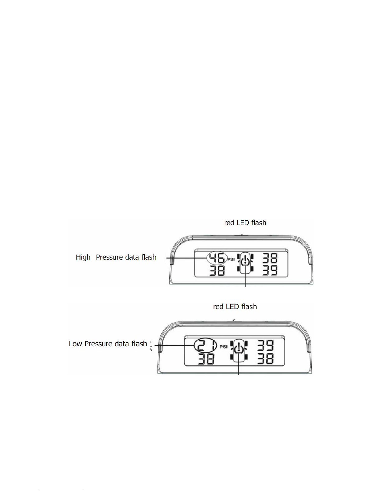
HIGH PRESSURE/LOW PRESSURE?HIGH TEMPERATURE ALERT
If a reading is outside of the users set parameters an audible alarm will sound
and the red LED will flash on the monitor. The alarm can be silenced by pressing
any button on the monitor. However the red LED will continue to flash until the
fault is removed and the monitor is back in the accepted settings range.
As an example
The settings are as follows
High Pressure alarm 46 psi
Low Pressure alarm 26 psi
Hi Temperature alarm 70 C
High Pressure alert Front Left Wheel
Low Pressure alert Front Left Wheel
Page 7
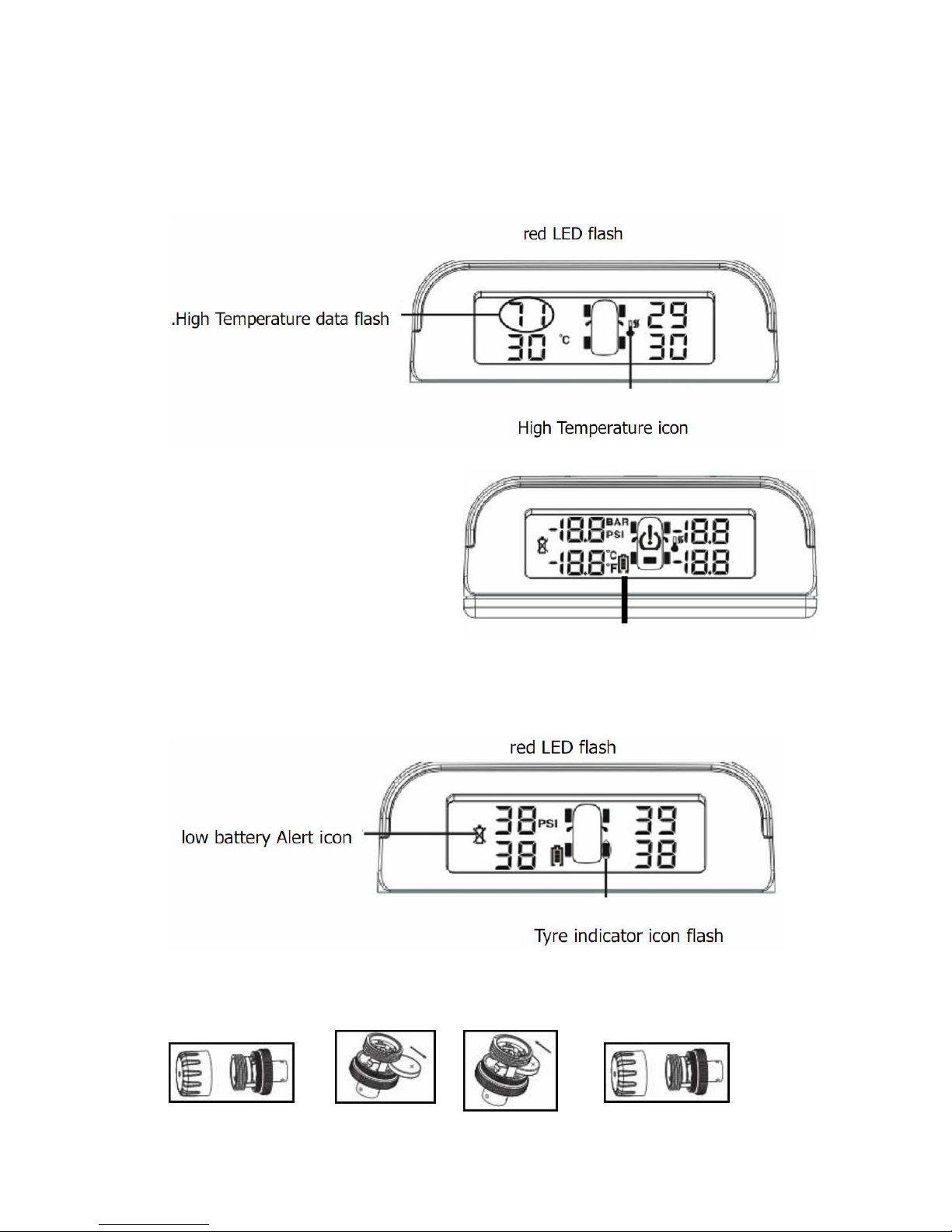
High Temperature alert Front Left Wheel
Monitor Low Battery
When the Monitor detects a low
Monitor battery level the low battery
icon will come on, however the low
battery icon will remain until the
monitor is recharged
Sensor Low Battery
When the Monitor detects a low Sensor battery level the low sensor battery icon
will come on and the location of the sensor will flash. There will also be an
audible warning and the red light will flash. Pressing any button will silence the
alarm, however the low battery icon and light will remain until the sensor battery
has been replaced
Replacing the Sensor Battery
Unscrew the sensor plastic cap slide out the CR1632 battery slide in a new
battery (POSITIVE UPWARDS) replace cap.
Page 8
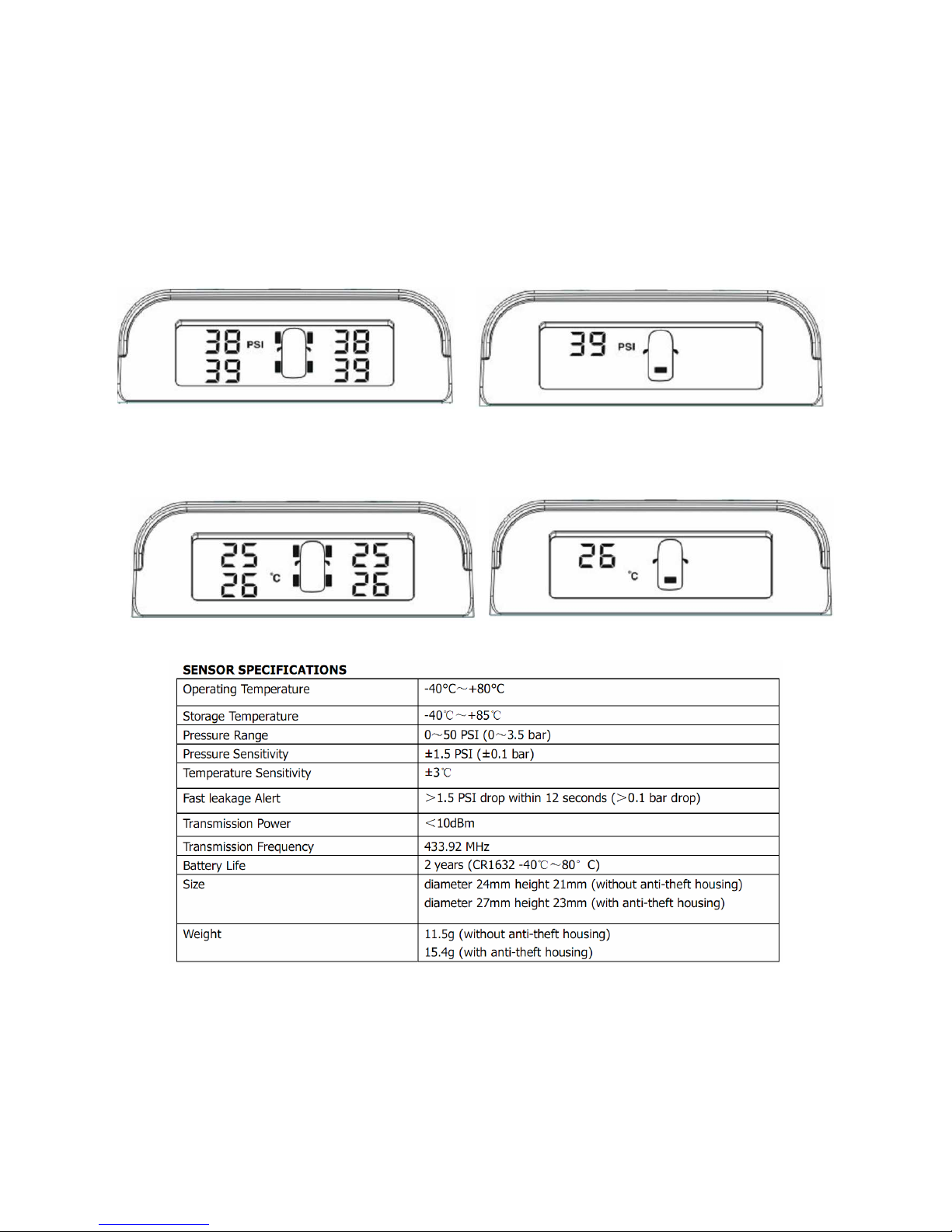
Data Display 2
The monitor will continually display the pressure settings for all tires and will
switch screens if an extra 5th sensor is installed.
By Pressing the SET button the Monitor will show the temperatures of each tire
as below for 5 seconds then switch back to pressure. The high temp alarm will
show if a tire reaches 70 degrees C
Page 9
GENERAL INFORMATION
Tire pressure recommended operating pressures should be set when the ambient temperature is
low or cold or where the tire has cooled down and is at a low temperature, out of the sun etc.
Dramatic changes in tire pressure can occur because of increased or decreased ambient
temperature; tire contact surface temperature etc, these and other situations should be taken into
consideration when setting initial tire operating pressures. This system cannot warn you of
impending side wall failures or blowouts, however it can supply you with irregular pressures and
temperature information that may help to prevent this. To test fast leakage response, unscrew a
sensor with monitor in range. The Track Master System, relies on a good air connection
between the Sensors and the tire valve (known as the Dill Valve) which is located inside the tire
valve stem.
The Dill Valve should be the correct size, be in good condition and be able to be depressed fully
to allow the release of air to the sensor so it can operate.
Some valve stem extensions may cause inaccurate readings if they do not allow the sensor to
operate correctly, standard short metal bodied stems are recommended for best performance.
Should you have difficulty with a pressure sensor not operating correctly we recommend that you
contact a tire professional to ensure that the tire stem and Dill Valve are installed and operating
correctly.
Do not use tire sealants when using this system. Over a period of time tires may lose pressure
naturally, through the tire itself or for other reasons such as rim leakage etc.
However after the Track Master valve sensors (including locking mechanism, if fitted) are
installed it is recommended that the sensor and valve stem be completely covered in a soapy
solution of 1 part liquid soap to 2 parts water, to see if there are any air bubbles coming from the
valve and sensor area indicating that the tire is leaking air.
If air bubbles are visualized in any of these areas, the tire may deflate and the Track Master,
system will not operate correctly. The wheel sensors are weatherproof and can be run in the rain.
A tire professional should be consulted should any of these areas prove to be a problem
Please note, Track Master Systems, operates on an RF system, as with many RF tire systems
this system can suffer from interference depending on the systems location thus causing the
system to be inaccurate or not operate at all. We cannot guarantee that the display will receive
the sensor signal accurately.
Purchasers of this product should not rely on this tire pressure monitoring system for safety and
should check the condition and pressure of their vehicles tires on a regular basis as described by
the manufacturer of the vehicle or tire manufacturer.
Tire pressures and temperatures are not the only things that can affect tire safety; we suggest
daily visual inspections and checks by tire professionals.
LIMITED WARRANTY
HawksHead will, within 12 months from date of original purchase, repair or replace free of charge
any defective component (except batteries) which upon careful inspection is found, in our sole
judgment, to have material or manufacturing defects, provided it is received freight prepaid,
accompanied by the original purchasers sales slip and an authorized Return Merchandise
Authorization number (RMA #.). You may obtain an RMA # by emailing [email protected]
DISCLAIMER OF WARRANTY: Neither the seller nor the manufacturer will be liable for any loss
damage or injury directly or indirectly arising from the use or inability to determine the use of this
product. Before using, the user shall determine the suitability of the product for its intended use,
and the user shall assume all responsibility and risk in connection herewith.
Page 10

PLEASE NOTE: SOME STATES DO NOT ALLOW LIMITATIONS ON HOW LONG IMPLIED
WARRANTIES MAY LAST OR DO NOT ALLOW EXCLUSIONS OR LIMITATIONS OF
INCIDENTAL OR CONSEQUENTIAL DAMAGES, SO THOSE EXCLUSIONS OR LIMITATIONS
MAY NOT BE APPLICABLE TO YOU.
© HawksHead Systems Inc
NOTES
 Loading...