

Page 1
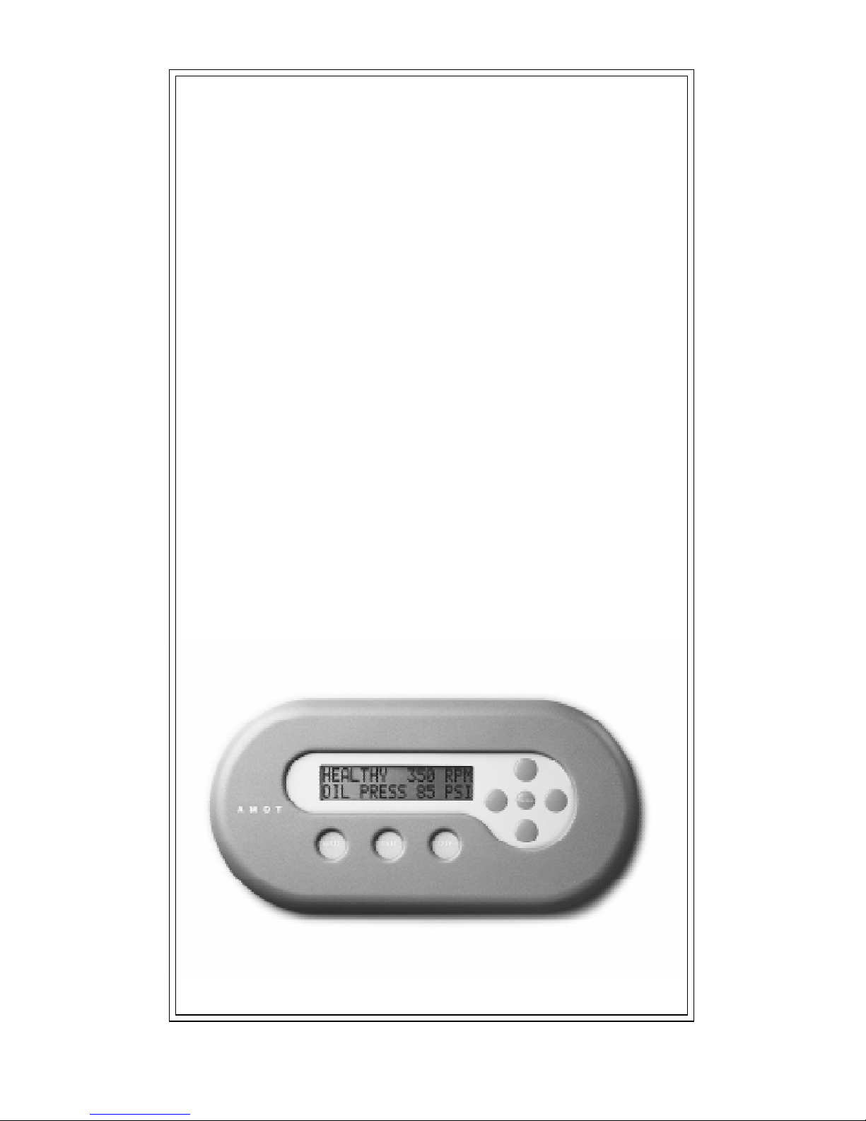
HAWK-I
USER MANUAL
™
Model 8630B
Hardware Manual
AMOT
CONTROLS
Page 2
i
© 1998 AMOT Controls Corp.
All Rights Reserved
Printed in USA
Trademarks used in this text:
Hawk-I and HawkWin are trademarks of AMOT Controls Corp. Windows and
Windows␣ 95 are registered trademarks of Microsoft Corporation. Modbus is a
registered trademark of Modicon Ltd. Other trademarks and trade names may be
used in this document to refer to either the entities claiming the marks and
names or their products. AMOT Controls Corp. disclaims any proprietary
interest in trademarks and trade names other than its own.
This document is based on information available at the time of its publication.
While efforts have been made to be accurate, the information contained herein
does not purport to cover all details or variations in hardware or software, nor to
provide for every possible contingency in connection with installation, operation,
or maintenance. Features may be described herein which are not present in all
hardware and software systems. AMOT Controls Corp. assumes no obligation of
notice to holders of this document with respect to changes subsequently made.
AMOT Controls Corp. makes no representation or warranty, expressed, implied,
or statutory with respect to, and assumes no responsibility for the accuracy,
completeness, sufficiency, or usefulness of the information contained herein. No
warranties of merchantability or fitness for purpose shall apply.
Use of DANGER, WARNING, CAUTION, and NOTE:
This publication includes DANGER, WARNING, CAUTION, and NOTE
information where appropriate to point out safety related or other impor-
tant information.
DANGER: Hazards which could result in severe personal injury or death.
WARNING: Hazards which could result in personal injury.
CAUTION: Hazards which could result in equipment or property damage.
NOTE: Alerts user to pertinent facts and conditions.
Although DANGER and WARNING hazards are related to personal injury,
and CAUTION hazards are associated with equipment or property damage,
it should be understood that the operation of damaged equipment could,
under certain conditions, result in degraded system performance leading to
personal injury or death. Therefore, comply fully with all DANGER,
WARNING, AND CAUTION NOTICES.
Page 3

Table of Contents
ii
1. INTRODUCTION
1.1 Easy and Flexible Programming ............................. 1-1
1.2 Other Key Features................................................. 1-1
1.3 Scaling and Signal Processing................................. 1-2
1.4 RS–232C Communications Port ............................ 1-2
2. SPECIFICATIONS
2.1 Inputs..................................................................... 2-1
2.2 Outputs .................................................................. 2-1
2.3 Communications.................................................... 2-2
2.4 Display ................................................................... 2-2
2.5 Environment .......................................................... 2-2
2.6 Power Supply.......................................................... 2-3
2.7 Hawk-I Specification Sheet .................................... 2-4
3. INSTALLATION
3.1 Installation Overview ............................................. 3-1
3.2 Recommended Environment.................................. 3-1
3.3 Mechanical Installation.......................................... 3-1
3.4 Wiring Requirements ............................................. 3-4
3.5 Grounding Requirements ....................................... 3-4
3.6 Digital Inputs......................................................... 3-6
3.6.1 Selecting Fault Sensing Switches ........................ 3-6
3.6.2 Dry Contacts ..................................................... 3-6
3.6.3 Sealed and Precious Metal Contacts ................... 3-6
3.6.4 Normally Open and Normally Closed ............... 3-6
3.6.5 Using Relay Contacts as Sensor Switches............ 3-7
3.6.6 Connecting The Digital Inputs .......................... 3-7
3.7 The Thermocouple Inputs...................................... 3-8
3.7.1 Connecting the Thermocouple Inputs ............... 3-8
3.8 The 4-20 mA Sensor Inputs.................................... 3-9
3.8.1 Connecting the 4-20 mA Sensor Inputs ............. 3-9
3.9 The Tachometer Input............................................ 3-9
3.9.1 Connecting the Tachometer Input ................... 3-10
3.10 The Start and Stop Inputs .................................. 3-10
3.10.1 Connecting the Start and Stop Inputs ............ 3-10
3.11 The Power Supply .............................................. 3-10
3.11.1 Connecting the Power Supply ........................ 3-10
3.12 The RS232C Communications Port................... 3-11
3.12.1 Connecting the RS232C Port for Programming 3-11
3.12.2 Connecting the RS232C Port for Monitoring 3-12
3.13 The Configuration Link Input ........................... 3-12
3.13.1 Connecting the Configuration Link Input ..... 3-13
3.14 The Pulse Input.................................................. 3-13
3.14.1 Connecting the Pulse Input ........................... 3-13
3.15 The Standard Relay Outputs .............................. 3-13
3.15.1 Connecting the Standard Relay Outputs ........ 3-13
3.16 The Optional Digital Outputs............................ 3-13
3.16.1 Connecting the Optional Digital Outputs ..... 3-13
3.17 The 4-20 mA Analog Outputs ............................ 3-14
3.17.1 Connecting the 4-20 mA Analog Outputs ..... 3-14
4. TEST AND OPERA TION
4.1 Pre-Operation Test Procedure ............................... 4-1
4.2 Initial Check of Hawk-I Operation........................ 4-2
4.2.1 Configure Mode and Run Mode........................ 4-2
4.3 Troubleshooting the Installation ............................ 4-3
4.3.1 LED Status Indicator ......................................... 4-3
4.4 Hawk-I Does Not Operate ..................................... 4-3
4.5 Digital Input Channel Does Not Function............. 4-3
4.5.1 Common Wiring Problems................................ 4-4
4.5.2 Intermittent Wiring Problems............................ 4-5
4.5.3 Swapping Channels............................................ 4-6
4.6 Electromagnetic Interference (EMI)....................... 4-6
4.6.1 Symptoms of EMI ............................................. 4-6
4.6.2 Grounding ......................................................... 4-7
4,6,3 Ground Loops ................................................... 4-7
4.7 Before Contacting AMOT ...................................... 4-7
Page 4

3.9 The Tachometer Input............................................ 3-9
3.9.1 Connecting the Tachometer Input ................... 3-10
3.10 The Start and Stop Inputs .................................. 3-10
3.10.1 Connecting the Start and Stop Inputs ............ 3-10
3.11 The Power Supply .............................................. 3-10
3.11.1 Connecting the Power Supply ........................ 3-10
3.12 The RS232C Communications Port................... 3-11
3.12.1 Connecting the RS232C Port for Programming 3-11
3.12.2 Connecting the RS232C Port for Monitoring 3-12
3.13 The Configuration Link Input ........................... 3-12
3.13.1 Connecting the Configuration Link Input ..... 3-13
3.14 The Pulse Input.................................................. 3-13
3.14.1 Connecting the Pulse Input ........................... 3-13
3.15 The Standard Relay Outputs .............................. 3-13
3.15.1 Connecting the Standard Relay Outputs ........ 3-13
3.16 The Optional Digital Outputs............................ 3-13
3.16.1 Connecting the Optional Digital Outputs ..... 3-13
3.17 The 4-20 mA Analog Outputs ............................ 3-14
3.17.1 Connecting the 4-20 mA Analog Outputs ..... 3-14
4. TEST AND OPERA TION
4.1 Pre-Operation Test Procedure ............................... 4-1
4.2 Initial Check of Hawk-I Operation........................ 4-2
4.2.1 Configure Mode and Run Mode........................ 4-2
4.3 Troubleshooting the Installation ............................ 4-3
4.3.1 LED Status Indicator ......................................... 4-3
4.4 Hawk-I Does Not Operate ..................................... 4-3
4.5 Digital Input Channel Does Not Function............. 4-3
4.5.1 Common Wiring Problems................................ 4-4
4.5.2 Intermittent Wiring Problems............................ 4-5
4.5.3 Swapping Channels............................................ 4-6
4.6 Electromagnetic Interference (EMI)....................... 4-6
4.6.1 Symptoms of EMI ............................................. 4-6
4.6.2 Grounding ......................................................... 4-7
4,6,3 Ground Loops ................................................... 4-7
4.7 Before Contacting AMOT ...................................... 4-7
iii
Page 5

5. MAINTENANCE AND REPAIR
vi
5.1 Maintenance........................................................... 5-1
5.1.1 Cleaning ............................................................ 5-1
5.1.2 Battery Replacement .......................................... 5-1
5.1.3 Fuse replacement ............................................... 5-2
5.2 Repair..................................................................... 5-3
5.2.1 Returning Equipment for Repairs ...................... 5-3
6. CHANGING THE HAWK-I’S CONFIGURATION
6.1 The Hawk-I Keypad............................................... 6-1
6.2 Gaining Access to the Configuration Menus.......... 6-1
6.3 Moving Up and Down Between Menus.................. 6-2
6.4 Moving From Side to Side in a Menu..................... 6-2
6.5 Revising Data Within a Menu Box......................... 6-2
6.6 Exiting Configuration Mode .................................. 6-3
6.7 Precautions............................................................. 6-3
6.8 Descriptions of Individual Menu Boxes ................. 6-4
6.8.1 Controllers...................................................... 6-4
6.8.2 Analog User Input .......................................... 6-4
6.8.3 Hours Run/Power Down ................................ 6-4
6.8.4 Fault Logging.................................................. 6-4
6.8.5 Digital Inputs ................................................. 6-4
6.8.6 Analog Inputs ................................................. 6-4
6.8.7 Digital Outputs .............................................. 6-4
6.8.8 Analog Outputs .............................................. 6-5
6.8.9 Timers ............................................................ 6-5
6.8.10 Tachometer ..................................................... 6-5
6.8.11 Time of day .................................................... 6-5
6.8.12 User Switches .................................................. 6-5
6.8.13 Average Groups............................................... 6-5
6.8.14 Split Ranges .................................................... 6-5
6.8.15 User Setpoints ................................................. 6-5
6.8.16 Communications ............................................ 6-5
6.8.17 Test Mode Timer ............................................ 6-6
6.8.18 Diagnostics ..................................................... 6-7
6.8.19 Lock/Unlock................................................... 6-8
7. VIEW MODE
7.1 Descriptions of Individual Menu Boxes ................. 7-1
7.1.1 Controllers...................................................... 7-1
7.1.2 Analog User Input .......................................... 7-1
7.1.3 Unhealthy Channels ....................................... 7-1
7.1.4 Hours Run/Power Down ................................ 7-1
7.1.5 Fault Logging.................................................. 7-1
7.1.6 Digital Inputs ................................................. 7-1
7.1.7 Analog Inputs ................................................. 7-2
7.1.8 Digital Outputs .............................................. 7-2
7.1.9 Analog Outputs .............................................. 7-2
7.1.10 Timers ............................................................ 7-2
7.1.11 Tachometer ..................................................... 7-2
7.1.12 Time of day .................................................... 7-2
7.1.13 User Switches ..................................................7-2
7.1.14 Average Groups............................................... 7-2
7.1.15 Split Ranges .................................................... 7-2
7.1.16 User Setpoints ................................................. 7-2
7.1.17 Run Diagnostics.............................................. 7-3
7.1.18 Lock/Unlock................................................... 7-4
7.1.19 Test Mode ....................................................... 7-4
Page 6

7. VIEW MODE
7.1 Descriptions of Individual Menu Boxes ................. 7-1
7.1.1 Controllers...................................................... 7-1
7.1.2 Analog User Input .......................................... 7-1
7.1.3 Unhealthy Channels ....................................... 7-1
7.1.4 Hours Run/Power Down ................................ 7-1
7.1.5 Fault Logging.................................................. 7-1
7.1.6 Digital Inputs ................................................. 7-1
7.1.7 Analog Inputs ................................................. 7-2
7.1.8 Digital Outputs .............................................. 7-2
7.1.9 Analog Outputs .............................................. 7-2
7.1.10 Timers ............................................................ 7-2
7.1.11 Tachometer ..................................................... 7-2
7.1.12 Time of day .................................................... 7-2
7.1.13 User Switches ..................................................7-2
7.1.14 Average Groups............................................... 7-2
7.1.15 Split Ranges .................................................... 7-2
7.1.16 User Setpoints ................................................. 7-2
7.1.17 Run Diagnostics.............................................. 7-3
7.1.18 Lock/Unlock................................................... 7-4
7.1.19 Test Mode ....................................................... 7-4
vii
Page 7

1-1
1. INTRODUCTION
The Hawk-I system is a unique, highly advanced, programmable
controller combining the power of a PLC with the easy to use functionality of an embedded control system. This system allows safe, localized
scanning of digital inputs, temperatures, pressures, flows, electrical
currents and voltages, and fluid levels in machinery and industrial
processes. Built-in communications make the Hawk-I a powerful and safe
front end for hazardous-area data acquisition and alarm annunciation.
1.1 Easy and Flexible Programming
The graphical programming interface to the Hawk-I system allows the
user to overcome the rigid constraints of conventional EPROM-based
equipment. AMOT’s innovative Ladder Logic lets even the novice
programmer set up new system functions easily and quickly.
HawkWin, the Windows 95, 98, NT based configuration software used to
program the Hawk-I system, was developed from AMOT’s long experience
in embedded controllers. The most critical problem with embedded controllers is the inability to make fast, on-site software changes, because the
programming of a typical embedded controller is contained in an EPROM
chip that cannot be altered. Software changes in such a system must be made
at the factory, not in the field, taking up to several weeks to implement.
Hawk-I and HawkWin were created to overcome this limitation. Almost
any safety shutdown, data monitoring, or alarm function can be rapidly
programmed on-site using HawkWin. Then the function sequence is
downloaded into Hawk-I through a standard RS232 Null Modem cable
from the PC.
1.2 Other Key Features
The Hawk-I is based on an expandable platform. The basic system
supports 16 discrete inputs, 4 power relay outputs, and a speed input to
sense RPM. It can be expanded to include 8 or 16 thermocouples, 8 or
16 4-20 mA loop inputs, 2 PID 4-20 mA loop outputs, and 8 low power
relays. (NOTE: Unit may be configured with no more than 24 analog
inputs total and no more than 16 of one specific type).
A communications option allows connection to a modem or Distributed
Control System (DCS) via Modbus/RTU protocol.
The Hawk-I module features a tactile keyboard (NEMA 4) and a large,
high-contrast, 32-character display with backlight.
1.3 Scaling and Signal Processing
The Hawk-I contains scaling and linearizing circuits that provide
individual channel readouts in software selectable units such as Centi-
grade and Fahrenheit temperatures, psig, psia, psid, feet and inches,
meters and centimeters, inches of water, etc. Individually set alarm and
shutdown setpoints are available for each channel, as well as multiple
user-defined setpoints. Any channel can be configured to trip when the
channel input is less than or greater than the setpoint. Timer class logic
can also be associated with channels on an individual basis.
Input channels can be grouped together for signal averaging. The Hawk-I
can generate an alarm or shutdown based on the deviation of any single
channel from the average. Each input channel setpoint or averaging
group setpoint can be assigned to any selected digital output.
1.4 RS-232C Communications Port
The RS232C serial data port and Modbus/RTU protocol allow easy
interfacing to many types of PLCs and distributed control systems,
including Modicon, Allen-Bradley, and Fisher Provox. Modbus supports
one master and multiple slave units. Baud rate and Modbus ID number
can be set from the Hawk-I keypad.
Page 8

1-2
1.3 Scaling and Signal Processing
The Hawk-I contains scaling and linearizing circuits that provide
individual channel readouts in software selectable units such as Centigrade and Fahrenheit temperatures, psig, psia, psid, feet and inches,
meters and centimeters, inches of water, etc. Individually set alarm and
shutdown setpoints are available for each channel, as well as multiple
user-defined setpoints. Any channel can be configured to trip when the
channel input is less than or greater than the setpoint. Timer class logic
can also be associated with channels on an individual basis.
Input channels can be grouped together for signal averaging. The Hawk-I
can generate an alarm or shutdown based on the deviation of any single
channel from the average. Each input channel setpoint or averaging
group setpoint can be assigned to any selected digital output.
1.4 RS-232C Communications Port
The RS232C serial data port and Modbus/RTU protocol allow easy
interfacing to many types of PLCs and distributed control systems,
including Modicon, Allen-Bradley, and Fisher Provox. Modbus supports
one master and multiple slave units. Baud rate and Modbus ID number
can be set from the Hawk-I keypad.
Page 9

2-1
2. SPECIFICATIONS
The Hawk-I is an expandable-platform digital controller with many
available options that allow the user to select a powerful yet economical
control system.
2.1 Inputs
The sixteen discrete digital inputs used in the Hawk-I have volt-free contacts
and are non-incendive; any kind of input switching device can be used. There
is not enough energy in the circuit to ignite any gas mixture that may be
present. The minimum loop resistance for an ‘off’ state is 15kΩ, the scan rate
is 100 msec, and the response time is 100 msec.
The Hawk-I provides a speed input designed for use with an AMOT
magnetic pickup, which senses gear teeth to determine RPM.
The optional J and/or K-type thermocouple inputs may be used with an
expanded Hawk-I system. The available temperature range is -346º to 1940º
F, or -210º to 1060º C. Accuracy is better than 1% of FSD with a 100 ms
scan rate. The thermocouple input field connections are classified as nonincendive, since a thermocouple is a simple device that cannot store energy.
The field wiring is 37-Way D Type through a DB-37 connector.
The Hawk-I can provide optional 4-20 mA/two-wire analog inputs. These
inputs have an accuracy of ±0.5% of indicated parameter value with a scan
rate of 100 ms. Loop power of 15 Vdc (open circuit) is provided. These
analog inputs are designed for use with transmitters that are approved for use
in a Class I, Division 2 area and are non-incendive. The field wiring is 25Way D Type through a DB-25 connector. For hazardous area installations, if
non-approved end devices are used, wiring must pass through an approved
barrier.
2.2 Outputs
The basic Hawk-I system has four relay outputs. The outputs are solidstate (non-sparking) relays rated at 36Vdc, 1.75A. An external snubber
network is required when switching inductive loads. These outputs are
accessed through two-part Phoenix connectors on the back of the Hawk-I
module. The connectors can accept wire as large as 12 AWG, allowing
long wire runs without excessive signal loss.
S
INCE THESE RELAY CIRCUITS TRANSMIT POWER FROM
AUXILIARY
INCENDIVE
SEPARATED
A further option allows for eight low power, solid state relays. These
outputs are rated at 100 mA/36 V. Connections are made through a 9-
way, D type connector. One side of the relays is bussed common.
Two optional analog outputs can also be provided. These 4-20 mA
outputs can be used to transmit selected data to a remote receiver. The
accuracy is better than 0.75% of FSD with an update rate of 100 msec.
These analog outputs are designed to be attached to a 4-20mA receiver
that has been approved or recognized for use in a Class I, Division 2 area.
If a non-approved receiver is used, the analog output wiring must pass
through an approved barrier, when used in a hazardous area.
2.3 Communications
In addition to the I/O options, the Hawk-I has a 9-pin RS232C connec-
tor that can be used to connect the Hawk-I system with a modem, DCS,
or a PC for programming and configuration changes. The protocol is
Modbus/RTU. This additional programming capability is further
discussed in a separate AMOT manual that describes the HawkWin
computer program.
Signal levels on the RS232C port may be incendive. Any attached device
within a hazardous area must be approved or recognized for use within
that area.
2.4 Display
The Hawk-I controller has a large, high-contrast, backlit, 32-character
display on a NEMA 4 faceplate. This LCD is 16 character by 2-line.
System faults are identified in plain English, and display messages can be
configured into the Hawk-I unit by the user.
2.5 Environment
The Hawk-I is suitable for use only in Class I, Division 2, Groups A, B,
C and D, or non-hazardous locations. Wiring should be installed by
qualified personnel in compliance with local electrical codes.
Page 10

2-2
WARNING
S
INCE THESE RELAY CIRCUITS TRANSMIT POWER FROM
AUXILIARY
EQUIPMENT, THEY ARE CLASSED
INCENDIVE
. ALL ASSOCIATED WIRING MUST BE
SEPARATED
FROM NON-INCENDIVE WIRING BY AN
APPROPRIATE
DISTANCE.
A further option allows for eight low power, solid state relays. These
outputs are rated at 100 mA/36 V. Connections are made through a 9way, D type connector. One side of the relays is bussed common.
Two optional analog outputs can also be provided. These 4-20 mA
outputs can be used to transmit selected data to a remote receiver. The
accuracy is better than 0.75% of FSD with an update rate of 100 msec.
These analog outputs are designed to be attached to a 4-20mA receiver
that has been approved or recognized for use in a Class I, Division 2 area.
If a non-approved receiver is used, the analog output wiring must pass
through an approved barrier, when used in a hazardous area.
2.3 Communications
In addition to the I/O options, the Hawk-I has a 9-pin RS232C connector that can be used to connect the Hawk-I system with a modem, DCS,
or a PC for programming and configuration changes. The protocol is
Modbus/RTU. This additional programming capability is further
discussed in a separate AMOT manual that describes the HawkWin
computer program.
Signal levels on the RS232C port may be incendive. Any attached device
within a hazardous area must be approved or recognized for use within
that area.
2.4 Display
The Hawk-I controller has a large, high-contrast, backlit, 32-character
display on a NEMA 4 faceplate. This LCD is 16 character by 2-line.
System faults are identified in plain English, and display messages can be
configured into the Hawk-I unit by the user.
2.5 Environment
The Hawk-I is suitable for use only in Class I, Division 2, Groups A, B,
C and D, or non-hazardous locations. Wiring should be installed by
qualified personnel in compliance with local electrical codes.
Page 11
Electrical and RF interference immunity is designed into the Hawk-I,
with RFI screening in the case. The unit has a high reliability due to
conservative derating of electronic components. The internal printed
circuit boards are conformally coated for extra environmental protection.
The Hawk-I can operate in temperatures between -20º and 65º Centigrade.
The humidity limits are 5% to 95% non-condensing. The controller is
weather and UV protected, and will withstand vibration up to 10G at 100
Hz. The protective case is sealed to NEMA 4 (IP65, dust tight and protected
from water jets) from the front panel when properly installed.
2.6 Power Supply
The Hawk-I can be powered by either 12Vdc or 24Vdc. The 12-V input
can accept DC ranging from 9V to 18V. The 24-V input can accept DC
ranging from 18V to 36V. The supply should be capable of delivering 1A.
Maximum ripple should be 1V P-P. Power is supplied through a terminal
block on the rear of the Hawk-I.
2-3
Hazardous Approvals:
ETL:Class 1, Division 2
Groups A, B, C, & D
ETLFM 3810 CETL
FM 3611
CAN/CSA C22.2 No. 142
CAN/CSA C22.2 No. 2B
B.A.S.E.E.F.A.: Ex N II C
Power Requirements: Table A
Voltage: 24 Vdc (18-36 Vdc)
12 Vdc (9-18 Vdc)
Current: 500 mA max.(24V)
800 mA max. (12V)
Ripple: <1V pk-pk
Environment:
ETL B.A.S.E.E.F.A.
Temperature: 0° to 150°F 0° to 122°F
(-18° to 65°C) (-18° to 50°C)
Vibration: 0-10g @ 100 Hz
Sealing: NEMA4 from Front Panel
EMC: IEC 801-2(ESD), 801-3(RF Immunity)
Display:Table E
Type:Backlit LCD
Characters: 16 Chars X 2 Lines
Char Size: 8.05 X 5.5mm
Digital Inputs (Non-Incendive):
Type:Volt-Free Contacts
Number:16
Open Circuit: > 15 k ohms
Hawk-I™ Hardware Specifications
Page 12
2-4
Hazardous Approvals:
ETL: Class 1, Division 2
Groups A, B, C, & D
ETL FM 3810 CETL
FM 3611
CAN/CSA C22.2 No. 142
CAN/CSA C22.2 No. 2B
B.A.S.E.E.F.A.: Ex N II C
Power Requirements: Table A
Voltage: 24 Vdc (18-36 Vdc)
12 Vdc (9-18 Vdc)
Current: 500 mA max.(24V)
800 mA max. (12V)
Ripple: <1V pk-pk
Environment:
ETL B.A.S.E.E.F.A.
Temperature: 0° to 150°F 0° to 122°F
(-18° to 65°C) (-18° to 50°C)
Vibration: 0-10g @ 100 Hz
Sealing: NEMA4 from Front Panel
EMC: IEC 801-2(ESD), 801-3(RF Immunity)
Display: Table E
Type: Backlit LCD
Characters: 16 Chars X 2 Lines
Char Size: 8.05 X 5.5mm
Digital Inputs (Non-Incendive):
Type: Volt-Free Contacts
Number:16
Open Circuit: > 15 k ohms
Hawk-I™ Hardware Specifications
Speed Input (Non-Incendive):
Type: Magnetic Pickup
Number: 1
Signal: Zero Crossing >2V pk-pk
Analog Inputs (Optional): Table C
Type: 4-20mA, 2-wire Transmitter,
(Non Incendive)
Number: 8 or 16
Accuracy: Better than 1% of FSD
Loop Power: 15 Vdc provided by the Hawk-I
Thermocouple Inputs (Optional): Table C
Type: J and/or K, (Non Incendive)
Number: 8 or 16
Accuracy: Better than 1% of FSD
Relay Outputs: Table B
Type: DC Solid State Relay
Number: 4
Rating: 3-36 V at 1.75 A (Continuous)
Isolation: 4 kV
Digital Outputs (Optional): Table B
Type: Solid State Relay, Common Ground
Number: 8
Rating: 36 V at 100 mA
Isolation: 1.5 kV (min)
Analog Outputs (Optional): Table D
Type: 4-20 mA (2-wire)
Number: 1 or 2
Accuracy: Better than 0.75% of FSD
Communications: Table F
Standard: RS232C
Protocol: MODBUS-RTU
Baud Rates: 300-19,200 Baud
Hawk-I
Page 13

2-5
Speed Input (Non-Incendive):
Type: Magnetic Pickup
Number: 1
Signal: Zero Crossing >2V pk-pk
Analog Inputs (Optional): Table C
Type: 4-20mA, 2-wire Transmitter,
(Non Incendive)
Number: 8 or 16
Accuracy: Better than 1% of FSD
Loop Power: 15 Vdc provided by the Hawk-I
™
Thermocouple Inputs (Optional): Table C
Type: J and/or K, (Non Incendive)
Number: 8 or 16
Accuracy: Better than 1% of FSD
Relay Outputs: Table B
Type: DC Solid State Relay
Number: 4
Rating: 3-36 V at 1.75 A (Continuous)
Isolation: 4 kV
Digital Outputs (Optional): Table B
Type: Solid State Relay, Common Ground
Number: 8
Rating: 36 V at 100 mA
Isolation: 1.5 kV (min)
Analog Outputs (Optional): Table D
Type: 4-20 mA (2-wire)
Number: 1 or 2
Accuracy: Better than 0.75% of FSD
Communications: Table F
Standard: RS232C
Protocol: MODBUS-RTU
Baud Rates: 300-19,200 Baud
Hawk-I™ Hardware Specifications
Page 14
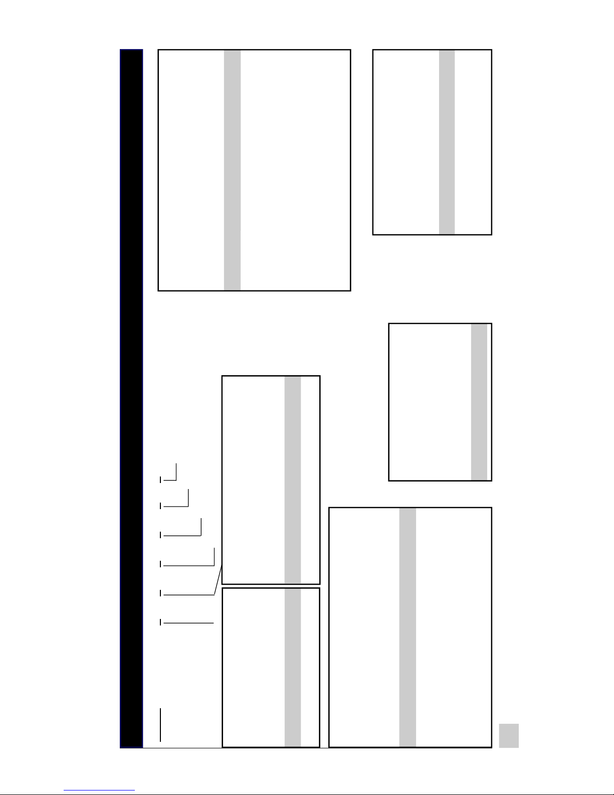
2-6
8630B
1 1
0 0 0
0
Basic
Model
Number
Model Code
Table C
Table D
Table E
Table F
Table A
Power Source
Code Input Power Options
1 24 VDC (18-36)
5 12 VDC (9-18)
Table B
Relays
Code Relay Options
1 4 DC Relays
3 4 DC Relays + 8 Aux. Outputs
Table C
Extended Board
Code Extended Input Options
0 Extended Board not Fitted
1 16TC Inputs
2 8 (4-20mA) Inputs
3 16TC Inputs + 8 (4-20mA) Inputs
4 8TC Inputs
5 16 (4-20mA) Inputs
6 8TC + 16 (4-20mA) Inputs
Table D
Analog Output
Code PID Options
0 PID Board not Fitted
1 Qty. 1 - PID for Grounded Load
2 Qty. 2 - PID for Grounded Load
Note: Extended Input Board must be
Fitted for use with PID Options 1 & 2
Table E
LCD
Code LCD Options
0 without Backlight
1 with Backlight
Table F
Communications
Code Options
0 HawkWin
1 HawkWin + Data Out
2 HawkWin + MODBUS
Basic Unit
Page 15

3. INSTALLATION
This chapter covers only the physical installation of the Hawk-I. The
Hawk-I digital controller must be programmed with a set of user-selected
functions before it can be put into service. The user first creates a
customized program for the Hawk-I with AMOT’s HawkWin software,
which is installed in an IBM-type host computer. Then the customized
program is downloaded from the PC into the Hawk-I. Once the Hawk-I
is in service, the program can be updated using the built-in keypad.
For further information about programming your Hawk-I with HawkWin
software, please consult AMOT’s HawkWin Programming Manual.
3.1 Installation Overview
The Hawk-I is often installed in a conventional equipment cabinet of the
enclosed type that can be used to hold a variety of electronic and
pneumatic control equipment. Mounting brackets are provided to hold
the unit in place. The environmental limitations listed on the Specifications Sheet should be observed. The Hawk-I is designed to be nonincendive for hazardous atmospheres, but retaining the non-incendive
characteristics of the equipment depends critically on proper installation,
good wiring practices, and the use of certified (or listed) end devices.
3.2 Recommended Environment
The Hawk-I is designed for continuous use (100% duty cycle) in an
ambient temperature ranging from 0º F to 150º F (-18º C to 65º C)
with a humidity of 5% to 95% (non-condensing). Site vibration must
not exceed 10G at 100 Hz.
3.3 Mechanical Installation
The Hawk-I enclosure requires a 1⁄
2
DIN cutout of 3.7 ± 0.1” by
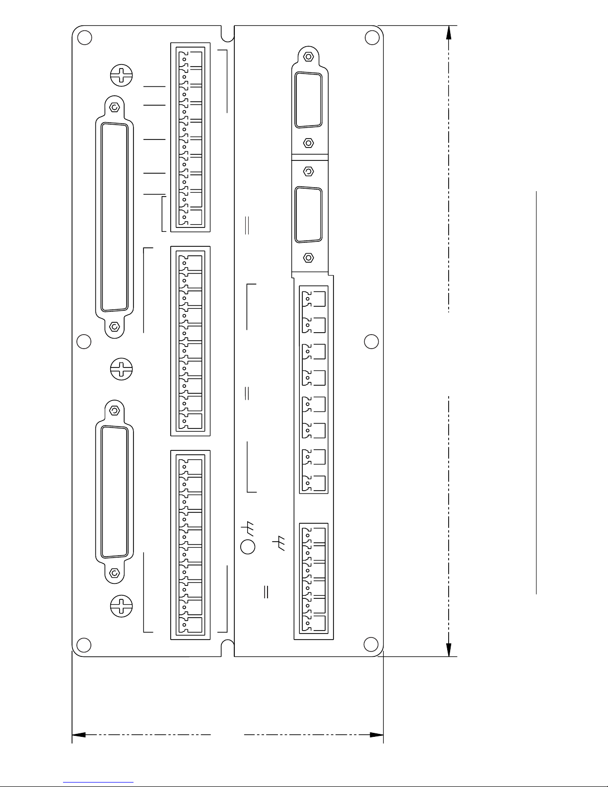
7.3 ± 0.1”, as dimensioned in Fig. 3-1.
To install the unit in a panel:
1. Insert the Hawk-I unit from the front of the panel.
2. Slide the two mounting brackets into the grooves along the
sides of the enclosure.
3. Install the two socket-head screws into the grooves to clamp
the unit in place. Note that to avoid stripping the threads, the
screws must not be overtightened.
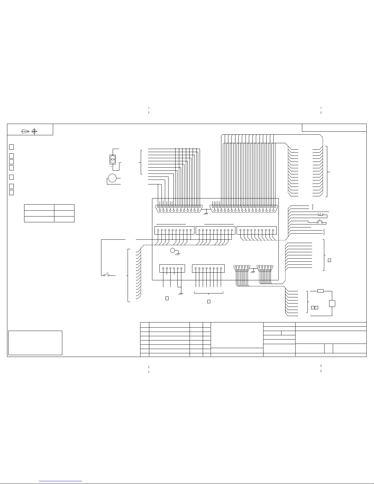
4. See Figs. 3-1 and 3-2 (AMOT Drawing No. 68630B-SD)
and the following text for wiring connections.
3-1
Page 16
–
PICK-UP
+
MAGNETIC
C
O
M
N/C
STOP
N/O
START
IN
PLS
LINK
CONFIG
THERMOCOUPLES
C
O
M
16151413
RS232C
AUX.
OUTPUTS
36 VDC 100mA MAX
RISQUE D'EXPLOSION–NE PAS DEBRANCHER TANT QUE LE CIRCUIT EST SOUS
TENSION, A MOIN QU'IL NE S'AGISSE D'UN EMPLACEMENT NON DANGEREUX
C
O
M
121110987654321
36 VDC 1.75A MAX
RELAY 1 RELAY 2 RELAY 3 RELAY 4
–+–+–+–
+
C
O
M
–
7.3 + 0.1"
Panel Cutout
WARNING AVERTISSEMENT
DISCRETE INPUTS–VOLT FREE CONTACTS
C
O
4–20mA INPUTS / OUTPUTS
M
NON–INCENDIVE FIELD WIRING CONNECTIONS FOR CLASS 1, DIVISION 2, GROUPS A, B, C & D
DC POWER
18–36V
[
–
N/C N/C
+
EXPLOSION HAZARD – DO NOT DISCONNECT WHILE CIRCUIT
IS LIVE UNLESS AREA IS KNOWN TO BE NON–HAZARDOUS
–
3.7 + 0.1"
Panel Cutout
Figure 3-1. Back view of the HAWK-I, showing connection points and panel cutout dimensions for mounting.
3-2
Page 17
68630B–SD
DWG
NO.
SHEET 1 OF 2
SHEET 1 OF 2
2
3
13
16
15
14
12
11
10
9
8
7
6
5
4
1
+
+
+
+
+
+
+
+
+
+
+
+
+
+
+
+
-
-
-
-
-
-
-
-
-
-
-
-
-
-
-
-
1TC
2TC
3TC
4TC
5TC
6TC
7TC
8TC
9TC
10TC
11TC
12TC
13TC
14TC
15TC
16TC
20
21
22
23
24
25
26
27
28
29
30
31
32
33
34
35
16
THERMO COUPLES
10
9
9
8
8
7
7
6
6
5
5
4
4
3
3
2
2
1
1
9
8
7
6
5
4
3
2
1
TACHO (ELECTROMAGNETIC
PICKUP HEAD)
COMMON
STOP N/C
START N/O
+
–
S1
S1
PULSE INPUT (TTL LEVELS)
CONFIG. LINK
TO MODEM
RS232C PORT
4
CD
DSR
RXD
TXD
CTS
DTR
RI
COMMON
RTS
AUX 1
AUX 2
AUX 3
AUX 4
AUX 5
AUX 6
AUX 7
AUX 8
AUX _COM
3 5
24V
+
–
LOAD
8 AUXILLARY
OUTPUT S
MATL :
FINISH :
TITLE :
HAWK - I SYSTEM DIAGRAM
AMOT
CONTROLS
SIZE
B
68630B - SD
DWG NO
RICHMOND, CA USA – BURY ST. EDMUNDS, SUFFOLK, ENGLAND
DWG CONTROL USA
DRAWN:
EW
CHKD:
DATE:
FILE:
APPROVAL:
SCALE:
2 MAY 97
68630BSDS1r4.DWG
MODEL
8630B
REDRAWN/ADDED SHEET 2
REVISION RECORD
4
REV
09/09/98
DATE
DKH
BY REMOVE ALL BURRS AND SHARP EDGES
SURFACE
ROUGHNESS
DO NOT SCALE DRAWING
.XX
.XXX
.XXXX
+
–
+
–
+
–
+
–
+
–
ANGLES
FRACTIONS
TOLERANCES UNLESS OTHERWISE SPECIFIED
DIMENSIONS ARE IN INCHES [MILLIMETERS]
AUX OUTPUTS RS232C
DB9 FEMALE
DB9 MALE
5 9 4 23 1
1 782 3 4
6
6
678 9 5
POWER CHASSIS
GND
++–
–
+–+–+
–
+
+
–
–
+–+–+
–
RELAY
1 2 3 4
RELAY OUTPUTS
1 3 4 5 6
7 8
2
1 3 4 5 62
18–36V DC
1
CHASSIS
GND
3 3 3 3 3 3 2 2 2 2 2 2 2 2 2 2
5 4 3 2 1 0 9 8 7 6 5 4 3 2 1 0
123456789
1011121314151
6
1
6
534
89 76 5 3
2 2 2
90 0 0
00
8 7
1
66534
4
2
9
9 8 7
153
4
2
9 887
7
1
6
534
2153 21 3 21
3
3
3
3
3
33 222 2
2
222
1111
1 1
1 122 111
222112
0
0
4
4
4 4
996
6
6
88775
5
5
3
3
3 3
1
1
1
111 1 1 1 11
12
22
2
04 96 87531 12 04 96 87531 12
1
11111
1
65 4 3 247
THERMOCOUPLES
DB37 FEMALE
4–20mA INPUTS/OUTPUTS
DB25 FEMALE
DISCRETE INPUTS
C CCC
C1, C2, C3, C4,
COMMON
CH1
CH2
CH3
CH4
CH5
CH6
CH7
CH8
CH9
CH10
CH11
CH12
CH13
CH14
CH15
CH16
16
DISCRETE
INPUTS
VOLT FREE
CONTACTS
14
1, 2, 3, 4, 5, 6, 7, 8
15
16
17
18
19
20
21
10
11
12, 13
1LP
2LP
3LP
4LP
5LP
6LP
7LP
8LP
LOOP POWER (15V MAX)
8 LOOP INPUTS
4–20mA
ANALOG OUT 1 (0–24mA)
ANALOG OUT 2 (0–24mA)
ANALOG OUTPUT RETURN
MA
–
+
+
THIRD ANGLE PROJECTION
NOTES: UNLESS OTHERWISE SPECIFIED
DC INPUT POWER: 36V 500mA MAX
(18V 800mA MAX 12V INPUT)
SOLID STATE RELAY OUTPUTS RATED 5–36V 1.75A MAX
AUXILLARY OUTPUTS– 36V 100mA MAX
NULL–MODEM TYPE CONNECTION REQUIRED FOR
INTERFACE TO A COMPUTER
PIN 5 OF AUXILLARY OUTPUT CONNECTOR MUST BE
CONNECTED TO AUX POWER GROUND
SNUBBER DIODE REQUIRED FOR INDUCTIVE LOADS
UNDOCUMENTED PINS SHOULD REMAIN DISCONNECTED
1.
2.
3.
4.
5.
6.
7.
MODEL NO. SHEET NO.
8630B__3___
8630B__6___12
AMOT CONTROLS CORPORATION RESERVES
PROPRIETARY RIGHTS TO THIS DRAWING
AND THE DATA SHOWN THEREON.
IT IS SUBMITTED IN CONFIDENCE FOR QUOTATION
OR ORDER OF THE PRODUCT SHOWN ONLY
SAID DRAWING AND/OR DATA ARE NOT
TO BE USED OR REPRODUCED FOR
ANY PURPOSE WITHOUT THE CONSENT OF
AMOT CONTROLS CORPORATION
Figure 3-2, Sheet 1
Page 18
THIRD ANGLE PROJECTION
LOOP POWER #1 (15V MAX)
LOOP POWER #2 (15V MAX)
9,25
22, 23, 24
14
15
16
17
18
19
20
10
11
12.13
21
1
2
3
4
5
6
7
8
1LP
2LP
3LP
4LP
5LP
6LP
7LP
8LP
LP9
LP10
LP11
LP12
LP13
LP14
LP15
LP16
8 LOOP INPUTS
4–20mA
8 LOOP INPUTS
4–20mA
ANALOG OUT 1 (0–24mA)
ANALOG OUT 2 (0–24mA)
ANALOG OUTPUT RETURN
MA
–
+
+ +
4–20mA INPUTS/OUTPUTS
DB25 FEMALE
3152214211320
1 2292
180
2
665 4
49 877 5
3
1 12111 1 1
163
89 76 5 3
2 2 2
90 0 08 7
1 3
2
9 8 7
153
4
21
6
534
21 3 21 3 21
3
3
33 222 2
2
1111
1 1
1
65 4 3 247
THERMOCOUPLES
DB37 FEMALE
04 96 87531 1204 96 87531 12
0 4 49653 311
1 1 1 1 11
2
CC
DISCRETE INPUTS
RELAY
4 6 87531122
CC
04 96 87531 12
C1, C2, C3, C4,
COMMON
CH1
CH2
CH3
CH4
CH5
CH6
CH7
CH8
CH9
CH10
CH11
CH12
CH13
CH14
CH15
CH16
16
DISCRETE
INPUTS
VOLT FREE
CONTACTS
+
–
18–36V DC
1
CHASSIS
GND
POWER CHASSIS
GND+ –
1 3 4 5 62
6
+–+–+–+
–
+–+–+–+
–
1 2 3 4
RELAY OUTPUTS
7 81 3 4 5 62
AUX OUTPUTS
DB9 FEMALE
RS232C
DB9 MALE
5 9 4 23 1
1 782 3 46678 9 5
9
8
7
6
5
4
3
2
1
TO MODEM
RS232C PORT
4
CD
DSR
RXD
TXD
CTS
DTR
RI
COMMON
RTS
10
9
8
7
6
5
4
3
2
1
TACHO (ELECTROMAGNETIC
PICKUP HEAD)
COMMON
STOP N/C
START N/O
+
–
S1
S1
PULSE INPUT (TTL LEVELS)
CONFIG. LINK
8
THERMOCOUPLES
2
3
8
7
6
5
4
1
+
+
+
+
+
+
+
+
-
-
-
-
-
-
-
-
1TC
2TC
3TC
4TC
5TC
6TC
7TC
8TC
20
21
22
23
24
25
26
27
2 2 2 2 2 2 2 2
7 6 5 4 3 2 1 0
12345678
68630B–SD
DWG
NO.
SHEET 2 OF 2
9
8
7
6
5
4
3
2
1
AUX 1
AUX 2
AUX 3
AUX 4
AUX 5
AUX 6
AUX 7
AUX 8
AUX _COM
3 5
24V
+
–
LOAD
8 AUXILLARY
OUTPUT S
SHEET 2 OF 2
MATL :
FINISH :
TITLE :
HAWK - I SYSTEM DIAGRAM
AMOT
CONTROLS
SIZE
B
68630B - SD
DWG NO
RICHMOND, CA USA – BURY ST. EDMUNDS, SUFFOLK, ENGLAND
DWG CONTROL USA
DRAWN:
EW
CHKD:
DATE:
FILE:
APPROVAL:
SCALE:
2 MAY 97
68630BSDS2r4.DWG
MODEL
8630B
09/09/98
DATE
DKH
BY REMOVE ALL BURRS AND SHARP EDGES
SURFACE
ROUGHNESS
DO NOT SCALE DRAWING
.XX
.XXX
.XXXX
+
–
+
–
+
–
+
–
+
–
ANGLES
FRACTIONS
TOLERANCES UNLESS OTHERWISE SPECIFIED
DIMENSIONS ARE IN INCHES [MILLIMETERS]
REDRAWN/ADDED SHEET 2
REVISION RECORD
4
REV
AMOT CONTROLS CORPORATION RESERVES
PROPRIETARY RIGHTS TO THIS DRAWING
AND THE DATA SHOWN THEREON.
IT IS SUBMITTED IN CONFIDENCE FOR QUOTATION
OR ORDER OF THE PRODUCT SHOWN ONLY
SAID DRAWING AND/OR DATA ARE NOT
TO BE USED OR REPRODUCED FOR
ANY PURPOSE WITHOUT THE CONSENT OF
AMOT CONTROLS CORPORATIONFigure
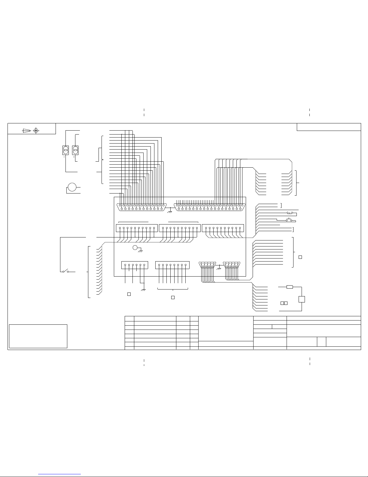
Figure 3-2, Sheet 2
Page 19
3.4 Wiring Requirements
The Hawk-I is Class I, Division 2 non-incendive equipment. The wiring
to the fault and sensing switches does not require explosion proof conduit
and housings. Such wiring cannot be the cause of a fire or an explosion.
The wiring must be kept separate from that of other electrical systems. If
the Hawk-I wiring is in the same enclosure as other wiring, keep a
minimum of two inches (2 in.) separation from the other wiring, and
securely hold the wiring in place by tie wraps or other means. Even
though explosion-proof conduit is unnecessary, give the wiring proper
mechanical protection. Use wire of good quality and of an insulation type
suitable for the environment.
WARNING
POWER AND HAZARDOUS AREA WIRING SHOULD BE
INSTALLED ONLY BY QUALIFIED PERSONNEL
Because of the small currents and voltages used, keep the sensor wiring
dry and keep splices to a minimum. If crimp-type wire terminations are
installed, use a crimping tool rated for use with the wire size and the lug.
Mismatch of a crimping tool to the wire and lug is a major source of poor
connections. Inspect each lug for correct compression of the crimp on the
cable conductor and the insulation.
Where conduit is used for protection of wiring, position it to avoid the
collection of moisture. In junction boxes or sensor enclosures where open
terminals are present, drain holes are recommended. The sensitivity of
the system to wiring practices is very low, but the value of good wiring
cannot be overestimated in the installation of electrical equipment.
3.5 Grounding Requirements
The back of the Hawk-I has 5 circuit ground terminals (see Fig. 3-1) that
are labeled COM (common), and 2 equipment ground terminals that are
labeled with an earth ground symbol.
There is also a power supply return terminal labeled with a minus (-)
sign. These terminals are not interchangeable, and if they are improperly
connected, the Hawk-I may not function properly.
There are three basic purposes for a ground or common terminal. The first
purpose is to ensure safety for operating personnel by providing electrical
equipment with a direct connection or short circuit to the earth. The second
purpose is to provide a direct connection to a circuit return point in a signal
circuit, and the third purpose is to provide a return circuit for a power supply.
These three different types of grounds must not be carelessly connected
together, even though they are all referred to as grounds.
3-4
For example, on the back of the Hawk-I, the sixteen discrete digital
switching inputs have four interconnected circuit return points labeled
COM. The circuit returns for the digital inputs can be connected to any
of these COM points. The COM terminals are input circuit grounds,
and serve to complete the digital switching circuits. They are not power
supply grounds or equipment safety grounds, and they must not be
connected to the dc power supply or the protective or chassis earth
ground connection.
The protective or chassis ground connection should be kept completely
separate from the circuit ground. The protective ground is intended to
keep the metal chassis of the Hawk-I at the same voltage as its surround-
ings, thus protecting the user from accidental electrical shock. This
requires a separate grounding wire (minimum size 14 AWG) that is not
connected to any other grounds. This protective ground wire should be
connected to the earth-ground terminal bolt on the Hawk-I’s back panel
and then bonded to a good earth ground connection point.
The negative ground for the dc power supply connection is a power
supply ground, and should be connected to the terminal labeled with a
minus (-) sign just below the word POWER on the back panel.
If shielded cable is used to run input wires to the Hawk-I, the shields of
the cables should be connected to the protective ground, not COM. Note
also that cable shields should be grounded only at the Hawk-I and
nowhere else. If a cable shield is grounded at more than one point,
“ground loop” currents may flow through the shield, making it useless.
Under normal conditions, shielded cable is recommended for the
RS232C, thermocouple, and analog loop connections.
The user should follow these simple guidelines and avoid improper intercon-
nections between circuit ground, protective ground, power supply ground,
and cable shield ground. Many hard-to-diagnose equipment problems,
including intermittent problems caused by transient electrical interference,
can be prevented by careful and effective grounding.
If your installation has unusually high levels of electrical interference,
special grounding arrangements may be required. Consult your AMOT
service representative for further details.
Page 20
For example, on the back of the Hawk-I, the sixteen discrete digital
switching inputs have four interconnected circuit return points labeled
COM. The circuit returns for the digital inputs can be connected to any
of these COM points. The COM terminals are input circuit grounds,
and serve to complete the digital switching circuits. They are not power
supply grounds or equipment safety grounds, and they must not be
connected to the dc power supply or the protective or chassis earth
ground connection.
The protective or chassis ground connection should be kept completely
separate from the circuit ground. The protective ground is intended to
keep the metal chassis of the Hawk-I at the same voltage as its surroundings, thus protecting the user from accidental electrical shock. This
requires a separate grounding wire (minimum size 14 AWG) that is not
connected to any other grounds. This protective ground wire should be
connected to the earth-ground terminal bolt on the Hawk-I’s back panel
and then bonded to a good earth ground connection point.
The negative ground for the dc power supply connection is a power
supply ground, and should be connected to the terminal labeled with a
minus (-) sign just below the word POWER on the back panel.
If shielded cable is used to run input wires to the Hawk-I, the shields of
the cables should be connected to the protective ground, not COM. Note
also that cable shields should be grounded only at the Hawk-I and
nowhere else. If a cable shield is grounded at more than one point,
“ground loop” currents may flow through the shield, making it useless.
Under normal conditions, shielded cable is recommended for the
RS232C, thermocouple, and analog loop connections.
The user should follow these simple guidelines and avoid improper interconnections between circuit ground, protective ground, power supply ground,
and cable shield ground. Many hard-to-diagnose equipment problems,
including intermittent problems caused by transient electrical interference,
can be prevented by careful and effective grounding.
If your installation has unusually high levels of electrical interference,
special grounding arrangements may be required. Consult your AMOT
service representative for further details.
3-5
Page 21

3.6 Digital Inputs
The Hawk-I is provided with 16 discrete digital inputs. The exact
configuration of these inputs is determined by the individual user’s
needs and the resulting HawkWin program. These digital switching
inputs have volt-free contacts and the circuits are non-incendive. Any
kind of volt-free, on-off sensor or sensing switch can be used with these
digital inputs without the risk of igniting an explosive atmosphere
under normal operating conditions.
3.6.1 Selecting Fault Sensing Switches
AMOT Controls manufactures many types of switches suitable for use
with the Hawk-I. Various types of switches are actuated at preset values
of pressure, temperature, vibration, etc.
The sensors selected should be of a type suitable for their mounting
location. For example, if sensors are skid-mounted on an outdoor installation, they should be of NEMA 4 construction as a minimum requirement.
3.6.2 Dry Contacts
The Hawk-I accepts any type of dry contact switch as an input. The
term “dry contact” means that during normal operation, the contacts
are completely isolated from other electrical systems. Solid state relays
and transistor outputs are not necessarily dry contacts unless specifically
approved for use in hazardous area locations. For more information,
refer to the relevant National Standard for non-incendive requirements.
The Hawk-I accepts the outputs of some active sensors such as smoke
detectors and pyrometers as sensor inputs. The only requirement is that
the device must have a dry contact output.
3.6.3 Sealed and Precious Metal Contacts
While environmentally or hermetically sealed switch contacts are
desirable as inputs, they are not the only choice. The advantage of
sealed contacts is that they cannot be corroded by the environment in
which the equipment is installed. Another common method of reducing
contact corrosion is the use of precious metal (e.g., gold) plating on the
contact surface. This plating is less susceptible to corrosion than
standard metals. AMOT can provide a full range of sensors.
3.6.4 Normally Open and Normally Closed
The digital fault sensors used by the Hawk-I can be of two forms,
normally open (NO) or normally closed (NC). The two types of sensors
are named according to their non-activated or healthy input state,
which can be either NO or NC.
3-6
Normally open sensors close to register a fault. A NO sensor can be
disabled if a wire is disconnected or broken, and the operator will not
know that the circuit has failed until that switch is tested for correct
operation. An NO sensor should be used only in non-safety applications
or when the risk of physical damage to wiring is low.
Normally closed sensors (NC) require a closed loop to each fault sensing
switch. They have the advantage of fail-safe operation. If a wire or sensor
is broken or disconnected, the Hawk-I will show that the circuit is
tripped, or in an open state.
Each of the 16 inputs of the Hawk-I can be individually configured for a
normally open or normally closed digital sensor. This feature allows the use of
both normally open and normally closed sensors in the same system.
3.6.5 Using Relay Contacts As Sensor Switches
There are two methods of using electromechanical relay contacts as fault
sensors without invalidating the non-incendive rating of the Hawk-I. The
first method permits the use of any standard relay, regardless of its design.
In this case, a barrier must be placed between the relay contacts and the
input wiring of the Hawk-I. The barrier must be mounted in a safe area
or an explosion proof box, depending on the mounting location.
The second method requires a relay specifically designed to connect between
incendive and non-incendive circuits. If this relay is mounted in a safe area or
an explosion proof housing, no further precautions are necessary.
The wiring for a non-incendive system must be kept separate from the
wiring of other electrical systems if the non-incendive status is to be
maintained. If the non-incendive wiring is in the same enclosure with
other wiring, it must be kept at least 2 inches from the other wiring. It
should also be secured in place by cable ties or other appropriate means.
The local non-incendive wiring code should always be followed.
Because of the small currents and voltages used in non-incendive circuits,
wire splices and their associated problems must be kept to a minimum.
3.6.6 Connecting The Digital Inputs
See Fig. 3-2, Hawk-I System Diagram, which shows all the inputs for the
Hawk-I. The discrete digital inputs are connected to the Hawk-I through
two 10-pin, plug-in, screw terminal, male-type “Phoenix plug” connec-
tors with a 5.08 mm pitch.
Shielding is usually not necessary for the digital inputs. These inputs are of
low impedance and are not normally vulnerable to electrical interference.
Page 22

Normally open sensors close to register a fault. A NO sensor can be
disabled if a wire is disconnected or broken, and the operator will not
know that the circuit has failed until that switch is tested for correct
operation. An NO sensor should be used only in non-safety applications
or when the risk of physical damage to wiring is low.
Normally closed sensors (NC) require a closed loop to each fault sensing
switch. They have the advantage of fail-safe operation. If a wire or sensor
is broken or disconnected, the Hawk-I will show that the circuit is
tripped, or in an open state.
Each of the 16 inputs of the Hawk-I can be individually configured for a
normally open or normally closed digital sensor. This feature allows the use of
both normally open and normally closed sensors in the same system.
3.6.5 Using Relay Contacts As Sensor Switches
There are two methods of using electromechanical relay contacts as fault
sensors without invalidating the non-incendive rating of the Hawk-I. The
first method permits the use of any standard relay, regardless of its design.
In this case, a barrier must be placed between the relay contacts and the
input wiring of the Hawk-I. The barrier must be mounted in a safe area
or an explosion proof box, depending on the mounting location.
The second method requires a relay specifically designed to connect between
incendive and non-incendive circuits. If this relay is mounted in a safe area or
an explosion proof housing, no further precautions are necessary.
The wiring for a non-incendive system must be kept separate from the
wiring of other electrical systems if the non-incendive status is to be
maintained. If the non-incendive wiring is in the same enclosure with
other wiring, it must be kept at least 2 inches from the other wiring. It
should also be secured in place by cable ties or other appropriate means.
The local non-incendive wiring code should always be followed.
Because of the small currents and voltages used in non-incendive circuits,
wire splices and their associated problems must be kept to a minimum.
3.6.6 Connecting The Digital Inputs
See Fig. 3-2, Hawk-I System Diagram, which shows all the inputs for the
Hawk-I. The discrete digital inputs are connected to the Hawk-I through
two 10-pin, plug-in, screw terminal, male-type “Phoenix plug” connectors with a 5.08 mm pitch.
Shielding is usually not necessary for the digital inputs. These inputs are of
low impedance and are not normally vulnerable to electrical interference.
3-7
Page 23

Each digital input needs to have its own ground return, so for every
digital input, two wires must be provided. For example, Digital Input 1
would have one side connected to Terminal 1 of the Phoenix connector.
The other side is connected to the COM terminal next to Terminal 4. Up
to 16 digital inputs may be connected to the Hawk-I.
3-8
3.7 The Thermocouple Inputs
The Hawk-I can be provided with optional thermocouple inputs of either
the J or K type. Type J has a continuous range up to 850ºC, and Type K goes
up to 1100ºC. The Hawk-I can monitor thermocouples as single devices, or
it can be programmed to average a number of thermocouple temperatures
and then respond to deviations from the average temperature.
3.7.1 Connecting the Thermocouple Inputs
The thermocouple inputs are connected to the Hawk-I through a
standard, 37-pin, female “D” type connector. When connecting a
thermocouple to the Hawk-I, the (-) arm always runs to a connector pin
that is numbered 20 or higher; the lower-numbered pins are reserved for
the positive legs. For example, Thermocouple 1 should have its positive
leg connected to Pin 1, and its negative leg connected to Pin 20. Refer to
Fig. 3-2, AMOT Drawing No 68630B-SD, for connection details.
Thermocouples are commonly installed, for example, on each cylinder
of a large internal combustion engine. If any one cylinder gets significantly hotter than the others, the Hawk-I can trigger an alarm or a
shutdown.
Selecting Fahrenheit or Centigrade is a simple point-and-click operation
with AMOT’s HawkWin software. The thermocouple type must also be
selected. Type J and K thermocouples can be mixed and matched in any
configuration that the user wants. The Hawk-I requires isolated (not
grounded) thermocouples.
If the user prefers to have screw terminals available for field wiring,
AMOT can provide interface boards to plug into the D-type connectors
(see Fig. 3-1). The terminal strips on these modules provide a fast and
easy way to connect input wires. Shielded cable must be used between the
Hawk-I and the interface module.
Pins 17, 18, 19, 36, and 37 (see Fig. 3-2) should not be connected to any
of the thermocouples. If shielded wire is used, terminate shields to the
case of the Hawk-I or the ground termination of the interface module.
If both J and K type thermocouples are required, it is best to organize the
connections in 2 blocks of 8 (1-8 and 9-16) where the majority of sensors
within each group is of the same type. For example, if 7 J-type and 8 K-type
sensors are used, put all the J-type sensors in one group and the K-type
sensors in another. This practice greatly simplifies the calibration process as
discussed later in this manual.
3.8 The 4-20 mA Sensor Inputs
The Hawk-I can be provided with optional analog inputs of the 4-20 mA
2-wire type. This is a popular configuration for industrial sensors of many
different kinds. The sensor input, which may be temperature, pressure,
flow, etc., is converted by a sensor circuit into an output current that
varies between 4 mA and 20 mA. Any voltage drop in the connector
wires becomes unimportant, since only the loop current is measured. The
data transmission path is low impedance and relatively immune to noise
pickup. The sensor circuitry is conveniently powered through the same
two wires that carry the output signal. There is no chance of confusing a
zero data reading with a broken wire, because at least 4 mA of current
must always flow through the sensor. A load resistor network inside the
Hawk-I converts the sensor output current into a precise voltage reading.
The calibration of the circuit is programmed by the user with AMOT’s
HawkWin program.
A wide variety of popular 4-20 mA sensors are approved as non-incendive
when connected to the Hawk-I. Your AMOT representative can provide
further information concerning the sensors, transducers, and transmitters
that are available for use with the Hawk-I’s 4-20 mA inputs.
Once the Hawk-I has received its initial programming from the
HawkWin software, the 4-20 mA inputs can be reconfigured as necessary
from the Hawk-I’s own key pad.
3.8.1 Connecting the 4-20 mA Sensor Inputs
The 4-20 mA sensors are two-terminal, polarity-sensitive devices. The
positive or (+) terminals must be connected to the positive terminals of
the 25-way D-type connector on the back of the Hawk-I. Likewise, the
negative or (-) terminals must be connected to the negative terminals of
the 25-way D-type connector on the back of the Hawk-I. Polarity is
important because the internal circuitry of the sensors is powered by a
+15 VDC power supply inside the Hawk-I. Please refer to Fig. 3-2
(Sheets 1 & 2) for the correct connection diagram.
Note: The 8-loop board is wired differently than the 16-loop board. Make sure that
you refer to the correct wiring diagram for the version you have. For all Hawk-I’s with an
Extended Board model code of 1, 2, or 3, refer to Sheet 1 of Fig. 3-2. For all Hawk-I’s
with an Extended Board model code of 4, 5, or 6, refer to Sheet 2 of Fig. 3-2.
The 4-20 mA sensors will be operational only after their output settings
are programmed by the HawkWin computer program. Alarm and
shutdown points can also be specified with just a few key strokes.
25-way interface modules are also available for these connections. Shielded
cable must be used between the Hawk-I and the breakout module.
Page 24

3-9
3.8 The 4-20 mA Sensor Inputs
The Hawk-I can be provided with optional analog inputs of the 4-20 mA
2-wire type. This is a popular configuration for industrial sensors of many
different kinds. The sensor input, which may be temperature, pressure,
flow, etc., is converted by a sensor circuit into an output current that
varies between 4 mA and 20 mA. Any voltage drop in the connector
wires becomes unimportant, since only the loop current is measured. The
data transmission path is low impedance and relatively immune to noise
pickup. The sensor circuitry is conveniently powered through the same
two wires that carry the output signal. There is no chance of confusing a
zero data reading with a broken wire, because at least 4 mA of current
must always flow through the sensor. A load resistor network inside the
Hawk-I converts the sensor output current into a precise voltage reading.
The calibration of the circuit is programmed by the user with AMOT’s
HawkWin program.
A wide variety of popular 4-20 mA sensors are approved as non-incendive
when connected to the Hawk-I. Your AMOT representative can provide
further information concerning the sensors, transducers, and transmitters
that are available for use with the Hawk-I’s 4-20 mA inputs.
Once the Hawk-I has received its initial programming from the
HawkWin software, the 4-20 mA inputs can be reconfigured as necessary
from the Hawk-I’s own key pad.
3.8.1 Connecting the 4-20 mA Sensor Inputs
The 4-20 mA sensors are two-terminal, polarity-sensitive devices. The
positive or (+) terminals must be connected to the positive terminals of
the 25-way D-type connector on the back of the Hawk-I. Likewise, the
negative or (-) terminals must be connected to the negative terminals of
the 25-way D-type connector on the back of the Hawk-I. Polarity is
important because the internal circuitry of the sensors is powered by a
+15 VDC power supply inside the Hawk-I. Please refer to Fig. 3-2
(Sheets 1 & 2) for the correct connection diagram.
Note: The 8-loop board is wired differently than the 16-loop board. Make sure that
you refer to the correct wiring diagram for the version you have. For all Hawk-I’s with an
Extended Board model code of 1, 2, or 3, refer to Sheet 1 of Fig. 3-2. For all Hawk-I’s
with an Extended Board model code of 4, 5, or 6, refer to Sheet 2 of Fig. 3-2.
The 4-20 mA sensors will be operational only after their output settings
are programmed by the HawkWin computer program. Alarm and
shutdown points can also be specified with just a few key strokes.
25-way interface modules are also available for these connections. Shielded
cable must be used between the Hawk-I and the breakout module.
Page 25

3.9 The Tachometer Input
The tachometer is a standard feature. It is connected to the Hawk-I through
a (10)-pin Phoenix connector that also handles several other inputs. The
tachometer signal is generated by a magnetic device that acts as a gear-tooth
counter. It is positioned close to a steel gear on the rotating machinery whose
RPM is to be monitored. The number of gear teeth that pass the tachometer
for each revolution of the machinery must be programmed into the Hawk-I.
If, for example, the crankshaft of a gas engine has a gear with 208 teeth on it,
then a tachometer mounted close to this gear will send 208 pulses per
revolution of the engine. Once this information is entered into the Hawk-I, it
handles the RPM calculation automatically.
3.9.1 Connecting the Tachometer Input
The tachometer wiring has (+) and (-) terminals. The magnetic pickup
gap should be set in the range of 0.025” to 0.050” for best results.
The tachometer will not function until it is calibrated with the
HawkWin program.
3.10 The Start and Stop Inputs
The normally-open (N/O) Remote Start and normally-closed (N/C)
Remote Stop inputs are controlled by switches or push buttons that are
connected to the Hawk-I by 2-conductor wires. The switch or push
button contacts are non-incendive. These switches duplicate the start and
stop buttons on the Hawk-I keypad, allowing remote operation or lockout capability. The functions of the Start and Stop keys are completely
programmable with the HawkWin computer program.
Until the Start and Stop keys are programmed with HawkWin, they have
no pre-defined function.
3.10.1 Connecting the Start and Stop Inputs
The Remote Start and Remote Stop inputs are connected to the Hawk-I
through the same 10-pin Phoenix connector that handles the tachometer
input. If these switches are not used, the Remote Stop inputs must be
shorted for normal operation. Connections may be made with any
convenient kind of two-conductor wire, preferably 18 AWG or larger.
These connections are non-incendive, so sealed switches are not required.
3.11 The Power Supply
The Hawk-I should be powered by a source of either nominal 24 Vdc or
12 Vdc at a minimum of 500 mA (see name plate on top of unit). Peakto-peak (P-P) ripple should not exceed 1 V.
3-10 3-11
3.11.1 Connecting the Power Supply
The power supply wiring must meet all local regulations and should be at least 16
AWG or better. All power supply wiring must have insulation with a breakdown
rating of at least 600 V, and be recognized, listed, or approved by a third party
agency (UL, CSA, etc.). The insulation must be rated for at least 75º C above the
surrounding ambient temperature.
The dc power is connected to the Hawk-I through an 6-pin Phoenix connector.
Proper polarity must be observed.
AMOT recommends that a 1A, 24Vdc circuit breaker or power isolation switch
be mounted close to the Hawk-I unit. This breaker will serve to remove power
from the unit for servicing purposes. This circuit breaker is a high-energy device,
and must conform to any safety requirements that are in force where it is located.
3.12 The RS232C Communications Port
The Hawk-I’s RS232C connection is an input-output port that allows the
Hawk-I to communicate with other equipment. When the CONFIG LINK
contacts on the back of the Hawk-I are shorted, the Hawk-I goes into
configuration mode. Then the RS232C input will act as a program loader to
accept programming inputted from the HawkWin configuration program.
When the CONFIG LINK contacts are opened, the Hawk-I goes into its
operational mode. Now the RS232C connection is not a program loader.
Instead, it provides an optional input-output Modbus/RTU connection
that supports remote monitoring and operation of the Hawk-I. Alterna-
tively, the RS232 port may be connected to a printer.
Through the RS232C serial data port, all data available to the Hawk-I
can be reported to a remote control center via the MODBUS for data
logging, trending, and analysis. Faults and output relay operations can be
reported through this data port,, including channel alarms, error mes-
sages, shutdowns, and power failures. A remote operator can monitor all
data channels by a read-only operation that does not interfere with local
use and control of the Hawk-I.
3.12.1 Connecting the RS232C Port for Programming
This input is connected by plugging the appropriate cable into the
RS232C socket. For configuration and programming, a suitable cable
will be connected to the HawkWin’s host computer, or to a portable
notebook computer that may be used to transfer the programming.
During day-to-day operation, the Hawk-I is connected to a cable that
runs to other monitoring and control equipment.
A null-Modem type connection is required for the programming connection.
The Hawk-I port is configured as DTE for direct connection to a modem.
Page 26

3.11.1 Connecting the Power Supply
The power supply wiring must meet all local regulations and should be at least 16
AWG or better. All power supply wiring must have insulation with a breakdown
rating of at least 600 V, and be recognized, listed, or approved by a third party
agency (UL, CSA, etc.). The insulation must be rated for at least 75º C above the
surrounding ambient temperature.
The dc power is connected to the Hawk-I through an 6-pin Phoenix connector.
Proper polarity must be observed.
AMOT recommends that a 1A, 24Vdc circuit breaker or power isolation switch
be mounted close to the Hawk-I unit. This breaker will serve to remove power
from the unit for servicing purposes. This circuit breaker is a high-energy device,
and must conform to any safety requirements that are in force where it is located.
3.12 The RS232C Communications Port
The Hawk-I’s RS232C connection is an input-output port that allows the
Hawk-I to communicate with other equipment. When the CONFIG LINK
contacts on the back of the Hawk-I are shorted, the Hawk-I goes into
configuration mode. Then the RS232C input will act as a program loader to
accept programming inputted from the HawkWin configuration program.
When the CONFIG LINK contacts are opened, the Hawk-I goes into its
operational mode. Now the RS232C connection is not a program loader.
Instead, it provides an optional input-output Modbus/RTU connection
that supports remote monitoring and operation of the Hawk-I. Alternatively, the RS232 port may be connected to a printer.
Through the RS232C serial data port, all data available to the Hawk-I
can be reported to a remote control center via the MODBUS for data
logging, trending, and analysis. Faults and output relay operations can be
reported through this data port,, including channel alarms, error messages, shutdowns, and power failures. A remote operator can monitor all
data channels by a read-only operation that does not interfere with local
use and control of the Hawk-I.
3.12.1 Connecting the RS232C Port for Programming
This input is connected by plugging the appropriate cable into the
RS232C socket. For configuration and programming, a suitable cable
will be connected to the HawkWin’s host computer, or to a portable
notebook computer that may be used to transfer the programming.
During day-to-day operation, the Hawk-I is connected to a cable that
runs to other monitoring and control equipment.
A null-Modem type connection is required for the programming connection.
The Hawk-I port is configured as DTE for direct connection to a modem.
Page 27

3.12.2 Connecting the RS232C Port for Monitoring
The Hawk-I’s optional communications module uses the RS232C to
transmit and receive information and commands from other monitoring
and control equipment. This is a convenient way to use the Hawk-I’s
powerful and economical monitoring and control capabilities as an
integrated part of a larger system.
All data collected by the Hawk-I can be transmitted to a remote control
center for logging, trending, and analysis. Faults and output relay
operations are also reported, including channel alarms and shutdowns,
error messages, and power failures.
The Hawk-I can transmit channel profiles and setpoint data immediately
upon request, giving a remote operator the ability to check the entire
configuration of the Hawk-I. Data can be remotely accessed at any time via
Modbus, and this does not interfere with the local operation. Both local and
remote operators can monitor channels, acknowledge alarms, and start or
stop the Hawk-I. However, only a local operator can change the Hawk-I’s
configuration or put the Hawk-I in test mode. All actions taken by a remote
operator are immediately available to the control center.
The Hawk-I’s internal communications module uses Modbus/RTU,
which is a high-level, widely-supported communications protocol. The
half-duplex, query/response program structure enables one remote master
to query and control many slaves. Modem and radio link capability
enable the Hawk-I to communicate over extremely long distances.
A number of software packages that support Modbus/RTU are now
available, such as The Fix by Intellution, Heuristics by ONSPET and
TOPDOC by Teledenken. These programs run on a variety of computer
systems. Contact your AMOT representative for additional information
concerning programs that can be used to interface other equipment with
the Hawk-I.
3.13 The Configuration Link Input
The configuration link input is used to prepare the Hawk-I to receive its
configuration programming from the HawkWin software, allowing local
configuration and access to the diagnostics features. After the two configuration link contacts are connected, the Hawk-I is ready to accept programming. These two contacts may be shorted by running a wire jumper between
the appropriate terminals on a plugged-in Phoenix connector. A small SPST
toggle switch may also be used. A series of menus (discussed later in this
document) allow local configuration and test.
3-12
3.13.1 Connecting the Configuration Link Input
This is done by shorting the two configuration link terminals. It may be
useful to put a red tag on the jumper wire or toggle switch to remind the
technician to open the link after programming is completed. The Hawk-I
will not process its sequence instructions with the configuration link closed.
3.14 The Pulse Input
This input is not used in the current Hawk-I configuration.
3.14.1 Connecting the Pulse Input
No connection of any kind should be made to this input.
3.15 The Standard Relay Outputs
The basic Hawk-I system is equipped with 4 internal solid-state relays
(Relays 1-4) that can control 5-36 Vdc with a maximum continuous current
of 1.75 A each. These relays can be used for various control, alarm, and
shutdown functions as programmed by the user. The relay outputs act as
switches that are powered by auxiliary equipment, and as such are classed as
incendive. Appropriate precautions should be taken if a hazardous atmo-
sphere is present. These internal relays achieve a circuit isolation of 4 kV
using optical isolation technology. Outboard snubbers are required for
inductive loads.
3.15.1 Connecting the Standard Relay Outputs
The relay outputs are connected to external circuits through individual,
two-terminal, Phoenix connectors, which can accept wire sizes as large as
12 AWG. Polarity must be observed on the DC connections.
3.16 The Optional Digital Outputs
The Hawk-I can be equipped with 8 optional, low-power, solid-state
relays to control external relays or low-power circuits. They are capable of
switching 36 Vdc at 100 mA. These outputs are potentially incendive, so
appropriate wiring and relay housings must be provided for operation in
hazardous atmospheres.
3.16.1 Connecting the Optional Digital Outputs
The optional outputs are connected through a 9-pin, D-type connector
on the back of the Hawk-I. The pin numbers are shown in the Hawk-I
System Diagram (see Fig. 3-2). All relay contacts are connected to a
single negative (-) signal return wire. An interface module can be
provided if the user requires screw terminal output connections.
Page 28

3.13.1 Connecting the Configuration Link Input
This is done by shorting the two configuration link terminals. It may be
useful to put a red tag on the jumper wire or toggle switch to remind the
technician to open the link after programming is completed. The Hawk-I
will not process its sequence instructions with the configuration link closed.
3.14 The Pulse Input
This input is not used in the current Hawk-I configuration.
3.14.1 Connecting the Pulse Input
No connection of any kind should be made to this input.
3.15 The Standard Relay Outputs
The basic Hawk-I system is equipped with 4 internal solid-state relays
(Relays 1-4) that can control 5-36 Vdc with a maximum continuous current
of 1.75 A each. These relays can be used for various control, alarm, and
shutdown functions as programmed by the user. The relay outputs act as
switches that are powered by auxiliary equipment, and as such are classed as
incendive. Appropriate precautions should be taken if a hazardous atmosphere is present. These internal relays achieve a circuit isolation of 4 kV
using optical isolation technology. Outboard snubbers are required for
inductive loads.
3.15.1 Connecting the Standard Relay Outputs
The relay outputs are connected to external circuits through individual,
two-terminal, Phoenix connectors, which can accept wire sizes as large as
12 AWG. Polarity must be observed on the DC connections.
3.16 The Optional Digital Outputs
The Hawk-I can be equipped with 8 optional, low-power, solid-state
relays to control external relays or low-power circuits. They are capable of
switching 36 Vdc at 100 mA. These outputs are potentially incendive, so
appropriate wiring and relay housings must be provided for operation in
hazardous atmospheres.
3.16.1 Connecting the Optional Digital Outputs
The optional outputs are connected through a 9-pin, D-type connector
on the back of the Hawk-I. The pin numbers are shown in the Hawk-I
System Diagram (see Fig. 3-2). All relay contacts are connected to a
single negative (-) signal return wire. An interface module can be
provided if the user requires screw terminal output connections.
3-13
Page 29

3.17 The 4-20 mA Analog Outputs
The Hawk-I can be equipped with 1 or 2 optional 4-20 mA analog
outputs. These analog outputs can transmit calibrated sensor data from
the Hawk-I to other equipment. The accuracy of these outputs is better
than 0.75% of FSD. These outputs are programmable from the
HawkWin program and can provide PID-type control functions.
3.17.1 Connecting the 4-20 mA Analog Outputs
The signals from analog outputs 1 and 2 are transmitted through Pins 10
and 11 of the 25-pin, D-type socket on the Hawk-I (see Fig. 3-2). The
signal return connections for these outputs are Pins 12 and 13 of the
same 25-pin connector.
3-14
4. TEST AND OPERATION
After the necessary wiring has been completed and the Hawk-I is
connected to all of the required inputs and outputs, the following
procedures should be followed to check out the Hawk-I’s installation.
4.1 Pre-Operation Test Procedure
1. The wiring is complete and checked out to ensure the required
continuity and freedom from inadvertent grounds.
2. The programming configuration is complete and checked for all
channels, parameters, and options.
5. When power is on with the Hawk-I, the LCD should display a
message. It should not be totally blank. The exact contents of the
display are dependent on the user program and the status of the
configuration link.
6. Check that each fault sensor operates correctly. Normally-open sensors
can be closed with a wire jumper, and normally closed sensors can be
opened by removing a wire from the appropriate terminal.
The checkout is best performed one channel at a time. After each
channel has been checked, the Hawk-I can be set to scan through all of
the input channels to verify their function.
If possible, each channel should be checked by exercising the actual fault
switch that is being used. This will identify wiring problems that prevent
a normally-closed circuit from opening when the circuit’s sensor is
activated. If it is difficult to exercise the actual sensor, the wiring can be
opened and closed at the sensor itself to simulate sensor action.
7. Each start disable function should be individually checked by
opening or shorting the wiring at the individual sensor.
8. All alarm horns and annunciators should be checked for proper function.
All safety and emergency functions should be checked with great care.
WARNING: ALL WIRING SHOULD BE INSTALLED IN
ACCORDANCE WITH LOCAL ELECTRICAL CODES
3. ALL PERSONNEL ARE CLEAR OF ANY OPERATIONAL
HAZARDS, ROTATING MACHINERY, WIRING, ETC.
4. Apply power to the Hawk-I while watching its LCD. If the display
remains blank, immediately remove power and check the wiring,
especially the power wiring. During the power-up sequence, the
Hawk-I should display:
Page 30
4. TEST AND OPERATION
After the necessary wiring has been completed and the Hawk-I is
connected to all of the required inputs and outputs, the following
procedures should be followed to check out the Hawk-I’s installation.
4.1 Pre-Operation Test Procedure
1. The wiring is complete and checked out to ensure the required
continuity and freedom from inadvertent grounds.
2. The programming configuration is complete and checked for all
channels, parameters, and options.
5. When power is on with the Hawk-I, the LCD should display a
message. It should not be totally blank. The exact contents of the
display are dependent on the user program and the status of the
configuration link.
6. Check that each fault sensor operates correctly. Normally-open sensors
can be closed with a wire jumper, and normally closed sensors can be
opened by removing a wire from the appropriate terminal.
The checkout is best performed one channel at a time. After each
channel has been checked, the Hawk-I can be set to scan through all of
the input channels to verify their function.
If possible, each channel should be checked by exercising the actual fault
switch that is being used. This will identify wiring problems that prevent
a normally-closed circuit from opening when the circuit’s sensor is
activated. If it is difficult to exercise the actual sensor, the wiring can be
opened and closed at the sensor itself to simulate sensor action.
7. Each start disable function should be individually checked by
opening or shorting the wiring at the individual sensor.
8. All alarm horns and annunciators should be checked for proper function.
All safety and emergency functions should be checked with great care.
4-1
WARNING: ALL WIRING SHOULD BE INSTALLED IN
ACCORDANCE WITH LOCAL ELECTRICAL CODES
Amot Controls
Hawk-I
3. ALL PERSONNEL ARE CLEAR OF ANY OPERATIONAL
HAZARDS, ROTATING MACHINERY, WIRING, ETC.
4. Apply power to the Hawk-I while watching its LCD. If the display
remains blank, immediately remove power and check the wiring,
especially the power wiring. During the power-up sequence, the
Hawk-I should display:
Page 31

WARNING
THE FRONT PANEL KEYS OF THE HAWK-I LABELED
“START” AND “STOP” WILL HAVE NO FUNCTION
UNLESS THEY ARE SPECIFICALLY PROGRAMMED
USING HAWKWIN
4.2 Initial Check of Hawk-I Operation
The programmer who used HawkWin to setup the Hawk-I should
provide a detailed operating procedure, possibly including a step-by-step
checklist. After checking the Hawk-I’s installation as described in Section
4.1 above, actual operation of the system can be verified.
The operation of the unit depends entirely on the programming sequence
that is downloaded from the HawkWin software. A detailed review of the
programming procedures for the Hawk-I is beyond the scope of this
manual. Please refer to the Hawk-I Programming Manual, which is
available from your AMOT representative.
4.2.1 Configure Mode and Run Mode
The Hawk-I must be in Run mode to be tested. Test personnel should
ensure that the CONFIG LINK connections on the back of the Hawk-I
are not shorted. When the CONFIG LINK connections are shorted, the
Hawk-I will go into its Configure mode, and will be ready to download
new sequence and analog diagrams from the HawkWin program. The
unit must also be in the Configure mode to edit parameters such as
analog set points and user display messages. However, if the programmer
has inadvertently left the Hawk-I in Configure mode, functional testing
cannot be carried out.
4-2
WARNING
IF A VALID SEQUENCE IS NOT PRESENT IN THE HAWK-
I AND THE UNIT GOES INTO RUN MODE:
IT WILL DE-ENERGIZE ALL RELAY OUTPUTS
IT WILL SET ALL ANALOG OUTPUTS TO 4 mA
THE SCREEN WILL DISPLAY THE MESSAGE “NO
SEQUENCE”
4.3 Troubleshooting the Installation
The Hawk-I’s operation depends on the input sensors that are connected
to the unit through wires and plug-in connectors. A wide variety of
malfunctions can be caused by external wiring errors.
4.3.1 LED Status Indicator
The Hawk-I is equipped with a green status LED (lamp) that is visible in
the opening between the power connector and the connector for relay
output #1. This LED indicates three conditions:
OFF: No power to the Hawk-I, or complete failure of the system.
ON: Internal software functioning properly.
FLASHING: Off for a short period once every second. This indicates
software failure or microprocessor failure.
The status indicator is helpful when trying to try and narrow down the
cause of problems. It provides a quick way to check the condition of the
fuse and power supply without opening the enclosure. It also helps to
distinguish between a software failure and power related problems.
During normal operation, the LED will always be illuminated.
4.4 Hawk-I Does Not Operate
NO POWER: Check status of dc power supply. Power must be supplied
to the proper connections on the Hawk-I with correct dc polarity and
voltage. The external circuit breaker must be ON. If the Hawk-I’s LCD
shows nothing at all and the backlight is not illuminated, the unit may
not be receiving power.
FUSE BLOWN: The Hawk-I’s internal protective fuse may be blown. In
this case, it must be replaced. Check all wiring connections before
reapplying power. See Section 5.1.3 for fuse replacement details. Replace
only with a fuse of the same voltage and current ratings.
4.5 Digital Input Channel Does Not Function
This is probably caused by a problem in the external wiring. If most of
the digital input channels function as programmed, then the problem is
probably not in the Hawk-I. Use View Mode, or Configure Mode, to
display all 16 digital input channels.
SUBSTITUTION TECHNIQUE: The technician will find it conve-
nient to prepare a SPST switch with two wires attached. By substituting
this switch for the two input wires of a digital channel, the function of
that particular channel can be verified.
Page 32
4.3 Troubleshooting the Installation
The Hawk-I’s operation depends on the input sensors that are connected
to the unit through wires and plug-in connectors. A wide variety of
malfunctions can be caused by external wiring errors.
4.3.1 LED Status Indicator
The Hawk-I is equipped with a green status LED (lamp) that is visible in
the opening between the power connector and the connector for relay
output #1. This LED indicates three conditions:
OFF: No power to the Hawk-I, or complete failure of the system.
ON: Internal software functioning properly.
FLASHING: Off for a short period once every second. This indicates
software failure or microprocessor failure.
The status indicator is helpful when trying to try and narrow down the
cause of problems. It provides a quick way to check the condition of the
fuse and power supply without opening the enclosure. It also helps to
distinguish between a software failure and power related problems.
During normal operation, the LED will always be illuminated.
4.4 Hawk-I Does Not Operate
NO POWER: Check status of dc power supply. Power must be supplied
to the proper connections on the Hawk-I with correct dc polarity and
voltage. The external circuit breaker must be ON. If the Hawk-I’s LCD
shows nothing at all and the backlight is not illuminated, the unit may
not be receiving power.
FUSE BLOWN: The Hawk-I’s internal protective fuse may be blown. In
this case, it must be replaced. Check all wiring connections before
reapplying power. See Section 5.1.3 for fuse replacement details. Replace
only with a fuse of the same voltage and current ratings.
4-3
4.5 Digital Input Channel Does Not Function
This is probably caused by a problem in the external wiring. If most of
the digital input channels function as programmed, then the problem is
probably not in the Hawk-I. Use View Mode, or Configure Mode, to
display all 16 digital input channels.
SUBSTITUTION TECHNIQUE: The technician will find it conve-
nient to prepare a SPST switch with two wires attached. By substituting
this switch for the two input wires of a digital channel, the function of
that particular channel can be verified.
Page 33

If the channel in question still does not function properly, then the
programming of the Hawk-I should be checked. But if the Hawk-I
responds correctly when the SPST switch is used to control the digital
input channel in question, then the problem must be either in the wiring
to the digital sensor for that input channel, or in the sensor itself.
The next step is to replace the sensor with a SPST switch and then check
channel function. If the channel functions properly, then the problem is
with the sensor. But if the channel still malfunctions, then the problem is
with the wiring.
The technician will find that the most useful tool for finding wiring
defects will be an ohmmeter. The digital contacts are volt-free, and the
wiring that controls them is either shorted or open. If the technician uses
a “buzzer” or some other ac signal source to “ring out” the wiring, care
should be taken not to route such test signals into the Hawk-I.
4.5.1 Common Wiring Problems
BROKEN WIRE: This will cause the channel to be always open. Wires
can be broken underneath the insulation, making the breakage invisible.
An ohmmeter check will confirm this kind of problem.
BAD SPLICE OR CRIMP: Often a crimping connector is accidentally
applied over unstripped wire. In this case, a new connector must be used to
repair the splice. If solder connections are used, they may also be defective. A
solder joint may look perfect but still be bad. If a continuity problem is
found, all solder connections should be reflowed using new solder.
CONNECTOR PROBLEMS: The technician should separate all
connectors in the circuit and look for broken parts, dirt and dust, or
foreign material. Blow out the female connectors with compressed air.
Check the wiring connections, either soldered or screw terminal, for
breaks and unstripped wire. Wires are highly stressed at connectors, and
breaks at connection points are quite common. The technician may
decide to cut off a few inches of the cable in question and restrip all the
wires. This will get rid of localized breaks that may be concealed by the
insulation of the individual conductors.
SENSOR PROBLEMS: If the sensor has both normally open (NO) and
normally closed (NC) contacts available, the wrong contacts may be
wired. This difficulty can be easily fixed by changing the Hawk-I’s
program, or the technician may decide to switch the wiring at the sensor
itself. The NO or NC status of a sensor’s output can be checked with an
ohmmeter. Be particularly suspicious of any riveted solder lugs on the
sensor to which connections must be made. Rivets frequently come loose
and cause continuity problems.
4-4
In industrial situations, mechanical failure seems to occur more fre-
quently than electronic failure. The moving parts of any sensor should be
examined carefully for freedom of movement and broken or jammed
linkages. Linear, back-and-forth movements such as those used in limit
switches seem to develop more problems than rotary movements.
All moving arms and levers associated with sensors should be examined
for freedom of movement as well as the buildup of rust or other deposits.
All springs used to control such linkages must be checked for weakness or
breakage. Note that if a spring has broken, the pieces of the spring may
have fallen off the linkage, so the absence of an essential spring may not
be immediately obvious.
Another kind of mechanical problem is the clogging of a small pipe or
tube that transmits pressure to a pressure sensor. All such tubes should
have blow-off valves so they can be easily checked for clogging. If a sensor
does not receive an accurate input, it cannot function properly.
Any sensor that appears to be corroded or damaged in any way should be
replaced immediately. The installation of the Hawk-I provides a good
opportunity for updating and modernizing sensors. Your AMOT representa-
tive can provide a wide selection of high-quality industrial sensors.
4.5.2 Intermittent Wiring Problems
If an input channel malfunctions only part of the time, this could also be a
wiring problem. Some possible causes of intermittent wiring problems are:
POOR CONNECTOR CONTACT: The connector for the channel in
question may not be making good mechanical contact. This problem
may surface only when heat, vibration, or mechanical stress are applied.
The technician may test for such a problem by wiggling the connector or
pulling on it. If this causes the problem to occur, the solution is to
replace the connector.
BROKEN WIRES: The broken ends of a wire may stay in contact part
of the time, and lose continuity only intermittently. Moving the wire
around and pulling on it may help to confirm this problem. Note that a
digital ohmmeter may be too slow in its response to show any change if
the loss of contact is momentary. The technician should check along the
entire length of the wiring in question for signs of stress such as a dented
conduit or a damaged cable shield or covering. In severe cases, the entire
wiring run may have to be replaced.
DAMAGED INSULATION: If insulation has been damaged, this may
permit intermittent contact between different conductors of a cable, or
between a conductor and the external shielding or conduit. In such cases, the
damaged section of wire must be replaced. There may be damage in more
than one location, so the safest procedure is to replace the entire run of cable.
Page 34

In industrial situations, mechanical failure seems to occur more frequently than electronic failure. The moving parts of any sensor should be
examined carefully for freedom of movement and broken or jammed
linkages. Linear, back-and-forth movements such as those used in limit
switches seem to develop more problems than rotary movements.
All moving arms and levers associated with sensors should be examined
for freedom of movement as well as the buildup of rust or other deposits.
All springs used to control such linkages must be checked for weakness or
breakage. Note that if a spring has broken, the pieces of the spring may
have fallen off the linkage, so the absence of an essential spring may not
be immediately obvious.
Another kind of mechanical problem is the clogging of a small pipe or
tube that transmits pressure to a pressure sensor. All such tubes should
have blow-off valves so they can be easily checked for clogging. If a sensor
does not receive an accurate input, it cannot function properly.
Any sensor that appears to be corroded or damaged in any way should be
replaced immediately. The installation of the Hawk-I provides a good
opportunity for updating and modernizing sensors. Your AMOT representative can provide a wide selection of high-quality industrial sensors.
4-5
4.5.2 Intermittent Wiring Problems
If an input channel malfunctions only part of the time, this could also be a
wiring problem. Some possible causes of intermittent wiring problems are:
POOR CONNECTOR CONTACT: The connector for the channel in
question may not be making good mechanical contact. This problem
may surface only when heat, vibration, or mechanical stress are applied.
The technician may test for such a problem by wiggling the connector or
pulling on it. If this causes the problem to occur, the solution is to
replace the connector.
BROKEN WIRES: The broken ends of a wire may stay in contact part
of the time, and lose continuity only intermittently. Moving the wire
around and pulling on it may help to confirm this problem. Note that a
digital ohmmeter may be too slow in its response to show any change if
the loss of contact is momentary. The technician should check along the
entire length of the wiring in question for signs of stress such as a dented
conduit or a damaged cable shield or covering. In severe cases, the entire
wiring run may have to be replaced.
DAMAGED INSULATION: If insulation has been damaged, this may
permit intermittent contact between different conductors of a cable, or
between a conductor and the external shielding or conduit. In such cases, the
damaged section of wire must be replaced. There may be damage in more
than one location, so the safest procedure is to replace the entire run of cable.
Page 35

4.5.3 Swapping Channels
Your Hawk-I unit was carefully checked before it was shipped. Even so, there
is a possibility that one of the digital input channels may be defective. If
wiring checks have not isolated the problem in a particular digital input
channel, then the programmer can reprogram the function of that channel to
another digital input, if an unused input is available.
If this procedure restores function, then the Hawk-I can be put back in service
at once without waiting for repairs, and considerable time can be saved.
4.6 Electromagnetic Interference (EMI)
Electromagnetic interference (EMI) can be described as an accidental and
undesirable form of radio broadcasting. The high-powered equipment
commonly found in industrial environments will frequently produce
strong magnetic, electrostatic, or electromagnetic fields. These fields will
then create undesirable voltages in nearby equipment.
To prevent these undesirable voltages, equipment designers can use
shielding, which is simply a method of screening out the strong ambient
fields. However, shielding is not as simple as it might appear. A shield
that will block radio-type or electromagnetic waves will not have the
slightest effect on a strong magnetic field from a nearby motor-generator
set. The following information will provide the technician with some
helpful guidelines for operation in environments with strong EMI.
4.6.1 Symptoms of EMI
The Hawk-I is housed in a metal case that is designed to keep out EMI.
However, if EMI gets into the external wiring of the Hawk-I, it can
penetrate the case and possibly cause problems.
What effect can powerful EMI signals have on the Hawk-I? The Hawk-I’s
digital circuitry can be upset or even damaged by high levels of EMI.
The result could be intermittent problems such as unintended system reset or loss
of memory that might be associated with the operation of nearby, high-powered
electrical equipment such as welders, motor controllers, and radio transmitters.
4.6.2 Grounding
Proper grounding is imperative to maintain the Hawk-I’s electrical safety
and immunity to EMI. Grounding requirements are discussed in Section
3.5 of this manual, and should be carefully followed. Special care should
be taken with the so-called earth ground.
The purpose of the earth ground is to maintain the chassis of the Hawk-I at
the same potential as the earth itself and provide a low impedance path for RF
noise away from the Hawk-I. This is usually done by connecting the earth
ground to a water or other metal pipe that has extensive contact with the
earth. A copper pipe is the best. Iron or steel pipes are not as good.
4-6
4.6.3 Ground Loops
If a large current of any kind flows through a grounding wire, the finite
resistance of the wire will cause a voltage difference between the ground
point and the far end of the wire. Any equipment “grounded” by that
wire will thus be raised above ground by the induced voltage, and the
“ground” will be of inferior quality.
The same effect can occur when the shielding of a cable is “grounded” at
several different points. The shield can then be driven above ground
potential by the large circulating currents. In such a case, the shielding
loses its effectiveness. It is clear that the technician must try to keep
accidental “ground loop” currents out of the Hawk-I’s wiring.
In difficult situations, the technician may have to try several grounding
points before an effective grounding connection is found.
4.7 Before Contacting AMOT
It may be necessary for a customer to contact AMOT about problems with a
Hawk-I installation. Before the customer picks up the phone, the following
information should be available:
1.
When did the problem first appear? Please be ready to give the date and the
time of day.
2. What was happening just before the problem occurred? What was the
equipment doing, and what was the operator doing? Did the operator observe
anything unusual just before the problem occurred? Was there any loud noise
or unusual vibration? Was the operator attempting to stop or restart the
equipment? Any unusual event may be of interest.
3. Did the technician who is contacting AMOT actually witness the problem in
person? This may be very important. Your AMOT representative may ask for
information that only an eyewitness can provide.
4. Any unusual environmental situation should also be reported. Was there a
nearby lightning strike or a power outage? A power surge? An earthquake that
might have damaged wiring? Excessive heat or cold?
5. Is there any printout or other record of equipment status or function at the
time that the problem occurred?
6. Has this problem or a similar one ever occurred before? How many times,
and on what dates? What was the outcome? How was the situation resolved?
7. Describe the most recent maintenance, repair, or reprogramming that was
done on the Hawk-I. When was it performed? And by whom?
8. After the specific problem in question occurred, what steps were taken to
correct it?
9. Does the on-site technician have any suggestions or recommendations to
make about the problem?
Giving accurate and complete information to your AMOT representative will
help to resolve system problems in a timely and effective fashion.
Page 36

4.6.3 Ground Loops
If a large current of any kind flows through a grounding wire, the finite
resistance of the wire will cause a voltage difference between the ground
point and the far end of the wire. Any equipment “grounded” by that
wire will thus be raised above ground by the induced voltage, and the
“ground” will be of inferior quality.
The same effect can occur when the shielding of a cable is “grounded” at
several different points. The shield can then be driven above ground
potential by the large circulating currents. In such a case, the shielding
loses its effectiveness. It is clear that the technician must try to keep
accidental “ground loop” currents out of the Hawk-I’s wiring.
In difficult situations, the technician may have to try several grounding
points before an effective grounding connection is found.
4.7 Before Contacting AMOT
It may be necessary for a customer to contact AMOT about problems with a
Hawk-I installation. Before the customer picks up the phone, the following
information should be available:
1.
When did the problem first appear? Please be ready to give the date and the
time of day.
2. What was happening just before the problem occurred? What was the
equipment doing, and what was the operator doing? Did the operator observe
anything unusual just before the problem occurred? Was there any loud noise
or unusual vibration? Was the operator attempting to stop or restart the
equipment? Any unusual event may be of interest.
3. Did the technician who is contacting AMOT actually witness the problem in
person? This may be very important. Your AMOT representative may ask for
information that only an eyewitness can provide.
4. Any unusual environmental situation should also be reported. Was there a
nearby lightning strike or a power outage? A power surge? An earthquake that
might have damaged wiring? Excessive heat or cold?
5. Is there any printout or other record of equipment status or function at the
time that the problem occurred?
6. Has this problem or a similar one ever occurred before? How many times,
and on what dates? What was the outcome? How was the situation resolved?
7. Describe the most recent maintenance, repair, or reprogramming that was
done on the Hawk-I. When was it performed? And by whom?
8. After the specific problem in question occurred, what steps were taken to
correct it?
9. Does the on-site technician have any suggestions or recommendations to
make about the problem?
Giving accurate and complete information to your AMOT representative will
help to resolve system problems in a timely and effective fashion.
4-7
Page 37
5. MAINTENANCE AND REPAIR
5-1
WARNING
EXPLOSION HAZARD
DO NOT DISCONNECT EQUIPMENT UNLESS POWER HAS BEEN
SWITCHED OFF OR THE AREA IS KNOWN TO BE NON-HAZARDOUS
5.1.1 Cleaning
If the Hawk-I keypad or enclosure requires cleaning, wipe the surfaces with a
damp cloth. Do not use solvents or abrasive cleaners on the Hawk-I.
5.1.2 Battery Replacement
WARNING
EXPLOSION HAZARD
BATTERY MUST BE REPLACED ONLY IN AN AREA KNOWN TO BE
NON-HAZARDOUS
A small internal battery is used to back up the Hawk-I’s active memory.
This battery should have a useful life of at least 3 years with the unit
unpowered. The drain on the battery is so low that the battery’s life will
be nearly equal to its shelf life. All parameters for the program are stored
in non-volatile memory that does not require battery backup. AMOT
recommends that the battery should be replaced every 36 months.
TO REPLACE THE BATTERY:
1. Switch off power to the Hawk-I.
2. Disconnect all wiring from the rear of the Hawk-I.
3. At the sides of the unit, remove the two socket-head screws and slide
out the two mounting brackets.
4. Remove the Hawk-I from the mounting panel and take it to a safe area.
5. At the back of the faceplate, remove six screws attaching the bezel.
Then remove the bezel.
6. At the front of the faceplate, remove six screws attaching the faceplate
to the unit housing.
7. Carefully tilt the faceplate outward to gain access to the cable connectors.
8. Carefully disconnect the cables and remove the faceplate.
5.1 Maintenance
The only maintenance required for the Hawk-I other than periodic
battery replacement is keeping the faceplate clean. Use a cloth dampened
with water to clean the faceplate. Do not use solvents; they could damage
the plastic membrane.
9. Note the location of the slots holding the three circuit boards.
Counting down from the top of the unit, the boards are installed in
slots 3, 7, and 13. To simplify reassembly, you may want to mark the
housing at the front ends of these slots with a pencil or marker.
10. Carefully slide out all three circuit boards as a group. Support the
boards so as not to stress the connections between them.
11. The internal battery is located at the left end of the CPU/Digital input
(middle) board. Carefully slide the battery out from its holder. Replace
the battery only with a unit of similar rating. See the Spare Parts List or
contact your AMOT representative for suitable spare parts.
12. Carefully align the three circuit boards with their correct slots in the
housing.
13. Slide the boards into place so that the rear connectors fit through
their openings in the housing.
14. Position the faceplate next to the front of the housing and carefully
connect the cables.
15. At the front of the faceplate, install six screws to attach it to the housing.
16. Align the bezel with the front of the faceplate. Be sure not to pinch
the cables when installing the faceplate.
17. At the back of the faceplate, install six screws to attach the bezel.
18. Insert the Hawk-I unit from the front of the panel.
19. Slide the two mounting brackets into the grooves along the sides of
the enclosure.
20. Install the two socket-head screws to clamp the unit in place. DO NOT
OVERTIGHTEN THE SCREWS; THE THREADS WILL STRIP.
21. At the rear panel, connect all wiring.
22. Power up the Hawk-I and test its operation. After battery replace-
ment, the Hawk-I will need to have its internal time and date set via
the CONFIG DIAGNOSTICS menu.
5.1.3 Fuse Replacement
The Hawk-I has an internal fast-blow fuse, 5 X 20 mm, 500mA, 250V
(800mA, 250V for 12V versions). See the Spare Parts List or contact your
local AMOT representative for suitable spare parts.
In order not to compromise the non-incendive classification of the
equipment, there is no externally-accessible fuse holder.
FUSE MUST BE REPLACED ONLY IN AN AREA KNOWN TO BE
Page 38
9. Note the location of the slots holding the three circuit boards.
Counting down from the top of the unit, the boards are installed in
slots 3, 7, and 13. To simplify reassembly, you may want to mark the
housing at the front ends of these slots with a pencil or marker.
10. Carefully slide out all three circuit boards as a group. Support the
boards so as not to stress the connections between them.
11. The internal battery is located at the left end of the CPU/Digital input
(middle) board. Carefully slide the battery out from its holder. Replace
the battery only with a unit of similar rating. See the Spare Parts List or
contact your AMOT representative for suitable spare parts.
12. Carefully align the three circuit boards with their correct slots in the
housing.
13. Slide the boards into place so that the rear connectors fit through
their openings in the housing.
14. Position the faceplate next to the front of the housing and carefully
connect the cables.
15. At the front of the faceplate, install six screws to attach it to the housing.
16. Align the bezel with the front of the faceplate. Be sure not to pinch
the cables when installing the faceplate.
17. At the back of the faceplate, install six screws to attach the bezel.
18. Insert the Hawk-I unit from the front of the panel.
19. Slide the two mounting brackets into the grooves along the sides of
the enclosure.
20. Install the two socket-head screws to clamp the unit in place. DO NOT
OVERTIGHTEN THE SCREWS; THE THREADS WILL STRIP.
21. At the rear panel, connect all wiring.
22. Power up the Hawk-I and test its operation. After battery replace-
ment, the Hawk-I will need to have its internal time and date set via
the CONFIG DIAGNOSTICS menu.
5.1.3 Fuse Replacement
The Hawk-I has an internal fast-blow fuse, 5 X 20 mm, 500mA, 250V
(800mA, 250V for 12V versions). See the Spare Parts List or contact your
local AMOT representative for suitable spare parts.
In order not to compromise the non-incendive classification of the
equipment, there is no externally-accessible fuse holder.
WARNING
EXPLOSION HAZARD
FUSE MUST BE REPLACED ONLY IN AN AREA KNOWN TO BE
NON-HAZARDOUS
5-2
Page 39
TO REPLACE THE FUSE:
1. Follow the steps indicated for replacing the battery, with the excep-
tion of Step 11.
2. The fuse is located near the power connector on the bottom board
(Power Supply).
5.2 Repair
With the exception of the internal battery and fuse, there are no fieldserviceable parts in the Hawk-I. If the unit malfunctions, it must be
returned to AMOT Controls or a factory-authorized repair center for test
and evaluation.
Any attempt by a customer to repair any part of the Hawk-I will void all
warranties. All repairs of the Hawk-I must be performed at an AMOTcertified repair facility.
WARNING
EXPLOSION HAZARD SUBSTITUTION OF COMPONENTS MAY
IMPAIR SUITABILITY FOR CLASS I, DIVISION 2
5.2.1 Returning Equipment For Repairs
If a Hawk-I unit or any Hawk-I circuit boards or other components are
being returned to AMOT for diagnosis and repair, the customer must
first contact an AMOT representative and obtain a Return Goods
Authorization (RGA). At that time, the customer will be given a specific
Return Goods Authorization (RGA) Number for that particular shipment.
AMOT will not accept any equipment for repair unless the RGA
procedure is followed. Any equipment sent to AMOT without the RGA
Number conspicuously displayed on the packaging will be returned to
the sender. Equipment should be shipped promptly after obtaining the
RGA Number, since all RGA Numbers automatically expire after 30
calendar days. Consult your AMOT representative for further details
concerning repairs.
Spare Parts List - Model 8630B
ITEM ................................................AMOT Part Number
Battery, 3V, 48mAh, BR1632 ................................................ 60364
Fuse, 250V, 500mA, 5 X 20 mm, Fast-Acting ....................... 51019L050
Fuse, 250V, 800mA, 5 X 20 mm, Fast Acting ....................... 51019L080
8 pos Phoenix MSTB ............................................................ 50576L008
6 pos Phoenix MSTB ............................................................ 50446L106
10 pos Phoenix MSTB .......................................................... 50446L110
Keypad .................................................................................. 60361L001
5-3 6-1
6. CHANGING THE HAWK-I’s
The Hawk-I is programmed with AMOT’s HawkWin software, which
enables the user to set up the sequence and analog ladder logic diagrams
that determine the basic functionality of the unit. However, after the
program is downloaded into the Hawk-I, everyday operation of the unit
is controlled by the built-in keypad.
6.1 The Hawk-I Keypad
The right side of the Hawk-I’s keypad contains five green keys, arranged like
a plus sign or +. The key in the middle of the + sign is labeled ENTER, and
the four remaining keys are placed at the ends of the plus sign’s four arms.
The buttons above and below the ENTER button are called the UP and
DOWN buttons. The buttons to the left and right of the ENTER button
are called the LEFT and RIGHT buttons. These designations give only a
general idea of the many functions that these buttons can perform while
accessing and updating the configuration settings.
WARNING: The front panel keys of the Hawk-I labeled START
and STOP will have no function unless they are specifically
programmed using HawkWin.
The keypad enables the user to navigate a configuration matrix that
allows the details of the programming to be updated and changed
whenever necessary. Figures 5-1 and 6-1 (Sheets 1-2) show the details of
this configuration matrix in the form of a flow chart. The Hawk-I user
will first scroll up or down in the matrix to find the particular menu that
is needed. Then the user can move to the right along the selected menu
to gain access to the menu box or boxes that must be changed.
6.2 Gaining Access to the Configuration Menus
1. Apply power to the Hawk-I through the connections on the rear panel.
2. The LCD should first say Amot Controls HAWK-I. After a few seconds,
the display will change either to the programmed display (if in Run
Mode), or indicate CONFIGURE MENU CONTROLLERS (if in
Configure Mode). The CONFIG LINK contacts must be connected
before the configuration procedure can be performed.
Note that if the unit is in View Mode, it will not go into Configure
Mode and the reconfiguration cannot be performed. There is also a
lockout coil (Configure Disable) that may be included in the Sequence
Diagram. Activating this coil will prevent the Hawk-I from entering
Configure Mode. If the configure link is present on power-up, the
Hawk-I will enter Configure Mode regardless of its programmed
Page 40
6. CHANGING THE HAWK-I’s
CONFIGURATION
The Hawk-I is programmed with AMOT’s HawkWin software, which
enables the user to set up the sequence and analog ladder logic diagrams
that determine the basic functionality of the unit. However, after the
program is downloaded into the Hawk-I, everyday operation of the unit
is controlled by the built-in keypad.
6.1 The Hawk-I Keypad
The right side of the Hawk-I’s keypad contains five green keys, arranged like
a plus sign or +. The key in the middle of the + sign is labeled ENTER, and
the four remaining keys are placed at the ends of the plus sign’s four arms.
The buttons above and below the ENTER button are called the UP and
DOWN buttons. The buttons to the left and right of the ENTER button
are called the LEFT and RIGHT buttons. These designations give only a
general idea of the many functions that these buttons can perform while
accessing and updating the configuration settings.
WARNING: The front panel keys of the Hawk-I labeled START
and STOP will have no function unless they are specifically
programmed using HawkWin.
The keypad enables the user to navigate a configuration matrix that
allows the details of the programming to be updated and changed
whenever necessary. Figures 5-1 and 6-1 (Sheets 1-2) show the details of
this configuration matrix in the form of a flow chart. The Hawk-I user
will first scroll up or down in the matrix to find the particular menu that
is needed. Then the user can move to the right along the selected menu
to gain access to the menu box or boxes that must be changed.
6.2 Gaining Access to the Configuration Menus
1. Apply power to the Hawk-I through the connections on the rear panel.
2. The LCD should first say Amot Controls HAWK-I. After a few seconds,
the display will change either to the programmed display (if in Run
Mode), or indicate CONFIGURE MENU CONTROLLERS (if in
Configure Mode). The CONFIG LINK contacts must be connected
before the configuration procedure can be performed.
Note that if the unit is in View Mode, it will not go into Configure
Mode and the reconfiguration cannot be performed. There is also a
lockout coil (Configure Disable) that may be included in the Sequence
Diagram. Activating this coil will prevent the Hawk-I from entering
Configure Mode. If the configure link is present on power-up, the
Hawk-I will enter Configure Mode regardless of its programmed
Page 41
sequence. This is a safety feature intended to prevent damage to equipment
controlled by the Hawk-I.
If the lockout coil is not used, be sure to stop any machinery controlled
by the Hawk-I. The Hawk-I will not respond to alarms or shutdowns
while in Configure Mode.
3. After the CONFIG LINK contacts are shorted, the LCD should say
CONFIGURE MENU CONTROLLERS. If these words are
displayed, you are in the configuration matrix. Note that CONFIGURE MENU CONTROLLERS identifies the menu box at the left
end of the first row of the Configuration Mode Flow Chart.
6.3 Moving Up and Down Between Menus
To step up and down from menu to menu in the configuration matrix,
use the UP and DOWN buttons. Note that if you press the UP button
immediately after accessing the matrix, the display will change from
CONFIGURE MENU CONTROLLERS to CONFIGURE MENU
LOCK/UNLOCK, which is the last menu in Sheet 2 of the Configuration Mode Flow Chart. If you press the DOWN button right after
getting into the matrix, the LCD should say CONFIGURE MENU
ANALOG USER IN. Stepping up and down in this way will enable the
user to access any menu in the matrix.
6.4 Moving From Side to Side in a Menu
When you have reached the menu where configuration changes must be
made, press ENTER. You will now be inside the row. Whenever you
want to exit the row, simply press the gray RESET button. If there is no
existing programming to be edited in a particular row, the LCD will
indicate ‘No instances of this type loaded.’ If any programming of that
kind is needed, it will have to be set up with AMOT’s HawkWin
software and then downloaded into the Hawk-I.
However, if there is existing programming in the selected row, then the
programming information will appear on the LCD. Program
reconfiguration can now begin.
6.5 Revising Data Within a Menu Box
To change anything that you see on the LCD, it must first be selected.
The blinking or on-off activity of a word, letter, or number within a
particular menu box indicates that this is the part of the box that will
change when the editing commands are used.
To make a particular number or word group blink, use the RIGHT and
LEFT buttons to step forward and backward through the current menu box.
When a particular word group is blinking, use ENTER to make the first
letter in the group blink. To move the blinking from one letter in the group
to the next, press the RIGHT and LEFT buttons. Note that the keypad will
6-2
select only words that can be edited. It will skip past formatting and label-
type words such as CLASS and NORMALLY that cannot be changed.
To enter the desired changes, use the UP and DOWN buttons to step the
display through all the options that are available. When the desired
information is displayed, press ENTER to change the Hawk-I’s configu-
ration. To move back and forth to adjoining menu boxes, use the
RIGHT and LEFT keys until the desired box appears on the LCD.
When all of the changes within a row are completed, use RESET to
return to the main menu structure. If changes have been made, the
display will prompt the user to press ENTER to confirm or RESET to
cancel. Pressing ENTER will save the changes to the Hawk-I’s non-
volatile memory. If RESET is pressed, the Hawk-I will ignore any
changes made in that menu.
Note that the Hawk-I contains a backup copy of the active, non-volatile
memory. The contents of active memory can be backed up by using the
‘Load Active Mem.’ option from the Diagnostics Menu. The backup
memory is also updated when a new sequence is downloaded to the
Hawk-I, or if the Hawk-I senses that it has been corrupted.
6.6 Exiting Configuration Mode
Configure Mode will exit only from the root configure menu. If the
configuration link is broken and the user is in a sub-menu, the Hawk-I
will remain in configure until the sub-menu is exited.
6.7 Precautions
WARNING: The functionality of the Hawk-I can be seriously
altered in Configure Mode. Use extreme care when making
changes to the Hawk-I’s configuration. Be sure to thoroughly
test and document any modifications.
DANGER: When in Diagnostics Mode, the Hawk-I outputs can
be manually toggled (or ramped). This is useful for system
troubleshooting, but can be extremely dangerous. Be sure
that all personnel are clear of hazards before activating
Page 42
select only words that can be edited. It will skip past formatting and labeltype words such as CLASS and NORMALLY that cannot be changed.
To enter the desired changes, use the UP and DOWN buttons to step the
display through all the options that are available. When the desired
information is displayed, press ENTER to change the Hawk-I’s configuration. To move back and forth to adjoining menu boxes, use the
RIGHT and LEFT keys until the desired box appears on the LCD.
When all of the changes within a row are completed, use RESET to
return to the main menu structure. If changes have been made, the
display will prompt the user to press ENTER to confirm or RESET to
cancel. Pressing ENTER will save the changes to the Hawk-I’s nonvolatile memory. If RESET is pressed, the Hawk-I will ignore any
changes made in that menu.
Note that the Hawk-I contains a backup copy of the active, non-volatile
memory. The contents of active memory can be backed up by using the
‘Load Active Mem.’ option from the Diagnostics Menu. The backup
memory is also updated when a new sequence is downloaded to the
Hawk-I, or if the Hawk-I senses that it has been corrupted.
6.6 Exiting Configuration Mode
Configure Mode will exit only from the root configure menu. If the
configuration link is broken and the user is in a sub-menu, the Hawk-I
will remain in configure until the sub-menu is exited.
6.7 Precautions
6-3
WARNING: The functionality of the Hawk-I can be seriously
altered in Configure Mode. Use extreme care when making
changes to the Hawk-I’s configuration. Be sure to thoroughly
test and document any modifications.
DANGER: When in Diagnostics Mode, the Hawk-I outputs can
be manually toggled (or ramped). This is useful for system
troubleshooting, but can be extremely dangerous. Be sure
that all personnel are clear of hazards before activating
outputs.
Page 43

6.8.1 Controllers
This menu allows configuration of the PID blocks. Users can modify the
action (direct/reverse), gain, integral, derivative, filter, and deadband
parameters for each PID in their analog diagram.
6.8.2 Analog User Input
This menu is used to set the value and descriptive text of any configured
analog user inputs.
6.8.3 Hours Run/Power Down
The contents of each run meter is displayed and can be set or reset. This
menu also shows the last power on time/date, and the last power down
time/date logged by the Hawk-I. The power on/off information can be
useful when tracking system failures or unannunciated shutdowns.
6.8.4 Fault Logging
This menu allows the viewing of the Hawk-I’s fault log. Each fault is time
and date stamped.
6.8.5 Digital Inputs
Changes can be made to the class (A, B, b, C), descriptive text, alarm/
shutdown classification, and normal status (open/closed) for all of the 16
digital inputs.
6.8.6 Analog Inputs
Changes can be made to the class (A, B, b, or C), descriptive text, low/
high shutdown setpoints, low/high shutdown enable/disable, low/high
alarm setpoints, and low/high alarm enable/disable for all of the analog
inputs. This menu allows the user to view the current input type and
units, i.e., a J type thermocouple displaying in ºC or a 4-20mA loop
displaying PSIG. The user can also view the calibration of loop transmitters, i.e., 4mA = 0 PSI, 20mA = 500 PSIG. These settings cannot be
altered from configure mode.
6.8.7 Digital Outputs
This menu allows the user to view and change the descriptive text
associated with each of the digital outputs.
6-4
6.8 Descriptions of Individual Menu Boxes
The menu boxes in the Hawk-I’s configuration matrix allow the user to
modify characteristics of the objects that are used in the Hawk-I’s ladder logic
without the requirement for a computer. A brief description of the Configure
Menu options follow. For complete information regarding the objects that
these menus control, see the HawkWin programming manual.
6.8.9 Timers
This menu allows the user to view and change the value and text for each
of the timers.
6.8.10 Tachometer
Changes can be made to the Pulses Per Revolution (PPR) of the tachometer,
the descriptive text, overspeed setpoint, underspeed setpoint, Crank Termina-
tion Speed (CTS), and Purge Permit Speed (PPS) from this menu.
6.8.11 Time of Day
This menu allows the user to view and change predefined software “Time
of Day” functions.
6.8.12 User Switches
This menu allows the user to view and change predefined software
“switches”. These switches give the user the capability of defining
alternate routines within the same program.
6.8.13 Average Groups
From this menu, the user can configure the descriptive text, group A
high/low deviations, and group B high/low deviations for each of the
average groups.
6.8.14 Split Ranges
This menu is used to modify the descriptive text, range for output A, and
range for output B for each of the split range controls.
6.8.15 User Setpoints
Use this menu to set the descriptive text, setpoint, hysteresis, and control
action (rising or falling) for each of the user setpoints.
6.8.16 Communications
From this menu, the user can select the Modbus access and communica-
tion speed. Some communications packages (FIX, for example) subtract 1
from the Modbus address before they transmit a request. The Hawk-I can
easily accommodate this by adding 1 to every incoming message address.
This adjustment (+1) is selected to be either yes or no.
6.8.8 Analog Outputs
This menu allows the user to view and change the descriptive text
associated with each of the analog outputs.
Page 44

6.8.9 Timers
This menu allows the user to view and change the value and text for each
of the timers.
6.8.10 Tachometer
Changes can be made to the Pulses Per Revolution (PPR) of the tachometer,
the descriptive text, overspeed setpoint, underspeed setpoint, Crank Termination Speed (CTS), and Purge Permit Speed (PPS) from this menu.
6.8.11 Time of Day
This menu allows the user to view and change predefined software “Time
of Day” functions.
6.8.12 User Switches
This menu allows the user to view and change predefined software
“switches”. These switches give the user the capability of defining
alternate routines within the same program.
6.8.13 Average Groups
From this menu, the user can configure the descriptive text, group A
high/low deviations, and group B high/low deviations for each of the
average groups.
6.8.14 Split Ranges
This menu is used to modify the descriptive text, range for output A, and
range for output B for each of the split range controls.
6.8.15 User Setpoints
Use this menu to set the descriptive text, setpoint, hysteresis, and control
action (rising or falling) for each of the user setpoints.
6.8.16 Communications
From this menu, the user can select the Modbus access and communication speed. Some communications packages (FIX, for example) subtract 1
from the Modbus address before they transmit a request. The Hawk-I can
easily accommodate this by adding 1 to every incoming message address.
This adjustment (+1) is selected to be either yes or no.
6-5
6.8.8 Analog Outputs
This menu allows the user to view and change the descriptive text
associated with each of the analog outputs.
Page 45

6-6
6.8.17 Test Mode Timer
This menu selects the duration of the test mode timer. The test mode
timer is used in conjunction with View Mode when testing sensors on an
active machine. Alarm and shutdown conditions will not trip output for
the duration of the timer. This value can range from 30 to 300 seconds.
6.8.18 Diagnostics
The diagnostics menu provides test functions for the inputs and outputs,
allows the system clock time and date to be set, and allows the active
memory to be loaded or saved, as well as analog input calibrations,
firmware version, date of last download, and number of downloads.
When toggling or ramping outputs, only one output at a time is active.
All others are off, or set to their minimum value.
Press RESET to exit a test menu and return to the Diagnostics Menu.
Pressing RESET a second time will return to the Configure Menu.
6.8.18.1 Key Test
This menu allows the user to test the functionality of
the keypad as well as the Remote Stop and Remote
Start switches.
6.8.18.2 Digital Inputs
Allows the user to verify the operation of the 16 digital
inputs.
6.8.18.3 Digital Outputs
Allows the user to verify the operation of the 4-12
digital outputs.
6.8.18.4 Analog Inputs
This menu allows the user to verify the operation of all
Analog Inputs without setting off alarms or sensor
failures.
6.8.18.5 Analog Outputs
This menu allows the user to verify the operation of 12 Analog Outputs by manually ramping each output
from 0% to 100%.
6.8.18.6 Hrs Run/Pwr Dn
Same as Section 6.8.3
6.8.18.7 System Clock
Allows the user to set the time and day.
6.8.18.10 Calibrate Inputs
Allows the user to calibrate analog inputs.
To calibrate an analog input(s):
• Select the input or group of inputs to be calibrated
• With the calibration source set at the defined value,
• Following the LCD prompt, set the first calibration
• Press the RIGHT button to accept the calibration
• Adjust the calibration source signal to reflect the
• Following the LCD prompt, set the second
• Press the RIGHT button to accept the second
After calibration, a message will appear indicating
success or failure. A failure indicates that the differ-
ence between the calibration source signal and the
corresponding calibration setpoint was too large for
compensation. This can happen if the calibration
source signal is not changed when entering the second
calibration setpoint; or if one of the calibration
setpoint values is incorrectly entered.
6.8.18.11 Firmware
Provides Firmware version and checksum
6.8.18.12 Sequence
Provides last sequence download date and time.
6.8.18.13 Accesses
Provides current download count.
6.8.18.8 Load Active Mem
Allows the user to load settings from ROM.
6.8.18.9 Save Active Mem
Allows the user to save changes to ROM.
Page 46

6.8.18.10 Calibrate Inputs
Allows the user to calibrate analog inputs.
To calibrate an analog input(s):
• Select the input or group of inputs to be calibrated
(T/C 1-8, T/C 9-16, individual T/C’s, or individual loops)
• With the calibration source set at the defined value,
apply the signal to the input(s) in question.
• Following the LCD prompt, set the first calibration
point.
• Press the RIGHT button to accept the calibration
source signal.
• Adjust the calibration source signal to reflect the
second set point and apply the signal as before.
• Following the LCD prompt, set the second
calibration point.
• Press the RIGHT button to accept the second
calibration source signal.
After calibration, a message will appear indicating
success or failure. A failure indicates that the difference between the calibration source signal and the
corresponding calibration setpoint was too large for
compensation. This can happen if the calibration
source signal is not changed when entering the second
calibration setpoint; or if one of the calibration
setpoint values is incorrectly entered.
6.8.18.11 Firmware
Provides Firmware version and checksum
6.8.18.12 Sequence
Provides last sequence download date and time.
6.8.18.13 Accesses
Provides current download count.
6-7
6.8.18.8 Load Active Mem
Allows the user to load settings from ROM.
6.8.18.9 Save Active Mem
Allows the user to save changes to ROM.
Page 47

6.8.19 Lock/Unlock
This is the security section of the Hawk-I. If the entered password does
not match the stored password, the Hawk-I will not allow configuration
changes from the keypad. The default password is 0, which allows open
access. Valid passwords range from 0 to 999.
6-8
6.8.18.14 Clr Calibration
Allows the user to reset all calibration settings.
6.8.18.15 Download Code
Allows the user to download new firmware via the
serial port.
7. Accessing the Hawk-I’s View Mode
After the system has been configured and is running a sequence, it may
be necessary to view the status of inputs, outputs, or other settings. In
addition, the user may want to change certain parameters without having
to stop the sequence and put the Hawk-I in Configure mode. The
number of parameters available to be modified in this mode is limited.
The user should refer to Section 7.1 to determine which parameters may
be modified in this mode.
View Mode may be accessed by pressing the ENTER button while the
Hawk-I is in Run Mode. Navigation of the View Mode menu is identical to
navigation within the Configure Mode menu (See Section 6). Keypad
functions are also identical and are defined in Sections 6.1, 6.3, 6.4, 6.5.
For a detailed view of the View Mode menu in flowchart form, refer to
Figure 7-1, Sheets 1 and 2.
7.1 Descriptions of Individual Menu Boxes
7.1.1 Controllers
This menu shows the current configuration of the PID blocks. Users can
modify the gain, integral, derivative, filter, and deadband parameters for
each PID in their analog diagram.
7.1.2 Analog User In
This menu shows the value and descriptive text of any configured analog
user inputs. Users can only modify the value for each analog user input
from this menu.
7.1.3 Unhealthy Channels
This menu shows any analog or discrete inputs that have gone unhealthy.
7.1.4 Hours Run/Power Down
This menu shows the status of all runtime meters as well as the last power
on time/date and the last power off time/date. No user modification is
possible from this menu
7.1.5 Fault Logging
This menu allows the viewing of the Hawk-I’s fault log. Each fault is time
and date stamped.
7.1.6 Digital Inputs
This menu shows the status, class, alarm/shutdown classification, and
descriptive text for all 16 digital inputs. No user modification is possible
from this menu.
Page 48
CONFIGURATION MODE
Full FLOWCHART fig. 6
CONFIGURE MENU
CONTROLLERS
CONFIGURE MENU
ANALOG USER IN
CONFIGURE MENU
HRS RUN / PWR DN
PID: 1
PID Controller
AU: 1 0.000
Analog User Input
RM: 1 0.00
RUNTIME METER
AUI: 1
0.000
Analog User Input
ACTION:
DIRECT
GAIN: 0.050
INTGRL:
9999.
DERIV: 0.000
INTGRL:
9999.
DERIV: 0.000
CONFIGURE MENU
FAULT LOGGING
PROGRAM DOWNLOAD
30-OCT-98 14:20
DI: 2 AL OP
Discrete Input
▲
▲
L-R
▲
▲
L-R
▲
▲
L-R
▲
▲
L-R
▲
▲
L-R
▲
▲
L-R
▲
▲
L-R
▲
▲
L-R
▲
▲
L-R
▲
▲
L-R
▲
▲
L-R
▲
▲
L-R
▲
▲
L-R
▲
▲
L-R
▲
▲
L-R
▲
▲
L-R
▲
▲
L-R
▲
▲
L-R
▲
▲
L-R
▲
▲
L-R
▲
▲
L-R
▲
▲
L-R
▲
▲
L-R
▲
▲
L-R
▲
▲
L-R
▲
▲
L-R
▲
▲
L-R
▲
▲
L-R
Note 1:
When word group is blinking, pressing Enter
will cause one character to blink.
When character is blinking:
- Pressing UP-Down buttons will step
through characters available.
- Pressing Left-Right buttons will select
adjacent characters.
When desired changes are completed,
press Enter.
Note 2:
When number group is blinking, pressing
Enter will cause decimal point to blink.
When decimal point is blinking, pressing
Up-Down buttons will increment-decrement
value of number.
When at desired value, press Enter.
CONFIGURE MENU
ANALOG INPUTS
CONFIGURE MENU
DIGITAL INPUTS
CONFIGURE MENU
ANALOG OUTPUTS
CONFIGURE MENU
TIMERS
CONFIGURE MENU TAC: 1 PPR: 0
TACHOMETER Speed
CONFIGURE MENU TIME/DATE: 1 TIME/DATE: 1
OCT
30 FRI OCT 30 FRI
TIME OF DAY OPEN VALVE
OPEN VALVE
EN EN EN
EN
EN EN
CONFIGURE MENU GRP:
1
GRP: 1 DEV A LO:
0.000
DEV A LO: 0.000 DEV B LO:
0.000
AVG GROUPS Group Average
Group Average
DEV A HI: 0.000 DEV A HI:
0.000
DEV B HI: 0.000
CONFIGURE MENU SR:
1
SR: 1 A:
0.000
= 0% A: 0.000 = 0% B:
0.000
= 0%
SPLIT RANGES Split Range
Split Range
0.000 = 100%
0.000
= 100% 0.000 = 100%
CONFIGURE MENU Setpoint:
1
Setpoint: 1 SP:
0.000
SP: 0.000
USER SETPOINTS Setpoint Constant Setpoint
Constant
HYS: 0.000 HYS:
0.000
DIAGNOSTICS EXIT: HOLD RESET
KEY TEST KEY:
DIAGNOSTICS Digital in Stat
DIGITAL INPUTS CCCCCCoCoCCCoCCC
DIAGNOSTICS
DIGITAL OUTPUTS
DIAGNOSTICS PARAMETER RESET
LOAD ACTIVE MEM RESET TO EXIT
(See Note 1) (REVERSE)
(See Note 2)
(2-12)
(2)
(2-64)
(no alternates)
(0-32000)
(Off)
(no alternates)
(See Note 1)
(See Note 2)
(See Note 2) (See Note 2)
(FALLING) (See Note) )(See Note 2)(See Note 1)
(2-255) (300, 600 1200,
2400, 4800, 9600)
(TX HIGH)
▲
▲
L-R
▲
▼
▲
▼
▲
▼
▲
▼
▲
▼
▲
▼
▲
▼
▲
▼
▲
▼
▲
▼
▲
▼
▲
▼
▲
▼
▲
▼
▲
▼
▲
▼
▲
▼
▲
▼
▲
▼
▲
▼
▲
▼
▲
▼
▲
▼
▲
▼
▲
▼
▲
▲
—Enter–
–Reset–
▲
▲
—Enter–
–Reset–
▲
▲
—Enter–
–Reset–
▲
▲
—Enter–
–Reset–
▲
▲
—Enter–
–Reset–
▲
▲
—Enter–
–Reset–
▲
▲
—Enter–
–Reset–
▲
▲
—Enter–
–Reset–
▲
▲
—Enter–
–Reset–
▲
▲
—Enter–
–Reset–
▲
▲
—Enter–
–Reset–
▲
▲
—Enter–
–Reset–
▲
▲
—Enter–
–Reset–
▲
▲
—Enter–
–Reset–
▲
▲
—Enter–
–Reset–
▲
▲
—Enter–
–Reset–
▲
▲
L-R
▲
▼
PID: 1
PID Controller
ACTION: DIRECT
GAIN:
0.050
FILTER:
1.000
DEADBAND: 0.000
(See Note 2)
(See Note 2)
(See Note 2)
(See Note 2)
(See Note 2)
FILTER: 1.000
DEADBAND:
0.000
AUI: 1 0.000
Analog User Input
(See Note 2)
▲
▲
L-R
(0-32000:59)
RM: 1
0.00
RUNTIME METER
(See Note 1)
RM: 1 0.00
RUNTIME METER
▲
▲
L-R
LAST POWER ON
02-JAN-98 7:24
▲
▲
L-R
Last Power Off
01-JAN-98 15:57
▲
▲
L-R
DI: 2 AL OP
01-FEB-98 8:45
▲
▼
DI: 10 SD OP
Discrete Input
DI: 10 SD OP
05-FEB-98 10:21
▲
▲
L-R
CONFIGURE MENU
DIGITAL INPUTS
▲
▲
—Enter–
–Reset–
DI: 1 CLASS:NONE
Discrete Input
DI: 1 CLASS:
NONE
Discrete Input
DI: 1 CLASS:NONE
Discrete Input
▲
▲
L-R
(See Note 1)
DI: 1 ALARM
NORMALLY OPEN
▲
▲
L-R
▲
▲
L-R
▲
▲
L-R
DI: 1
ALARM
NORMALLY OPEN
DI: 1 ALARM
NORMALLY
OPEN
(Shutdown) (Closed)
AI: 1 CLASS: NONE
Analog Input
AI: 1 CLASS:
NONE
Analog Input
(A, B, b, C)
▲
▲
L-R
AI: 1 CLASS: NONE
Analog Input
(See Note 1)
▲
▲
L-R
▲
▲
L-R
▲
▲
L-R
▲
▲
L-R
▲
▲
L-R
▲
▲
L-R
TYPE: Type J T/C
UNITS: C
LO AL:
0.000
DIS
HI AL: 0.000 DIS
LO AL: 0.000
DIS
HI AL: 0.000 DIS
LO AL: 0.000 DIS
HI AL:
0.000
DIS
(EN)
LO AL: 0.000 DIS
HI AL: 0.000
DIS
AO:
1
Analog Output
4mA:
0.000
20mA: 0.000
4mA VAL: 0.000
20mA VAL: 0.000
(EN)
DO:
1
Discrete Output
DO: 1
Discrete Output
(See Note 1)
▲
▲
L-R
▲
▲
L-R
AO: 1
Analog Output
(See Note 1)
▲
▲
L-R
▲
▲
L-R
4mA: 0.000
20mA:
0.000
(See Note 2) (See Note 2)
▲
▲
L-R
TMR: 1 VAL: 1
B Timer
TMR: 1 VAL: 1
B Timer
(See Note 1)
TMR: 1 VAL:
1
B Timer
▲
▲
L-R
▲
▲
L-R
(0-32000)
TAC: 1 PPR:
0
Speed
TAC: 1 PPR: 0
Speed
(See Note 1)
▲
▲
L-R
▲
▲
L-R
▲
▲
L-R
▲
▲
L-R
OVERSPD:
0
UNDERSPD: 0
OVERSPD: 0
UNDERSPD:
0
(0-32000)
(0-32000)
CTS:
0
PPS: 0
CTS: 0
PPS:
0
(0-32000)
(0-32000)
(See Note 1)
(DIS)
▲
▲
L-R
▲
▲
L-R
14
: 30
EN EN
14
: 30
EN EN
(DIS)
CONFIGURE MENU
USER SWITCHES
SUI: 1 ON
8 CYLINDER ENGINE
SUI: 1 ON
8 CYLINDER ENGINE
SUI: 1 ON
8 CYLINDER ENGINE
(See Note 1)
▲
▲
L-R
▲
▲
L-R
▲
▲
L-R
▲
▲
L-R
(See Note 2)
DEV B LO: 0.000
DEV B HI:
0.000
(See Note 2) (See Note 2)
(no alternates)
(See Note 1) (See Note 2)
B: 0.000 = 0%
0.000
= 100%
(See Note 2)
▲
▲
L-R
(no alternates)
ACTION:
RISING
CONFIGURE MENU
COMMUNICATIONS
ADDR:
1
BAUD: 19200
ADDR: 1
BAUD:
19200
ADDR+1:
NO
RTS: TX LO
ADDR+1: NO
RTS:
TX LO
(YES)
CONFIGURE MENU
TEST MODE TIMER
TEST MODE TIMER
SECONDS:
60
(30-300)
▲
▼
CONFIGURE MENU
DIAGNOSTICS
▲
▲
—Enter–
–Reset–
▲
▲
—Enter–
–Reset–
▲
▲
—Enter–
–Reset–
RELAY:
1
ENERGIZE RELAY
RELAY:
2
ENERGIZE RELAY
RELAY:
3
ENERGIZE RELAY
RELAY:
4
ENERGIZE RELAY
RELAY:
12
ENERGIZE RELAY
▲
▼
▲
▼
▲
▼
▲
▼
▲
▼
▲
▲
Enter
Reset
RELAY:
1
DEENERGIZE RELAY
RELAY:
2
DEENERGIZE RELAY
▲
▲
L-R
▲
▲
L-R
▲
▲
L-R
RELAY:
3
DEENERGIZE RELAY
RELAY:
4
DEENERGIZE RELAY
▲
▲
(L-R; Relays 5 through 11)
RELAY:
12
DEENERGIZE RELAY
▲
▲
—Enter–
–Reset–
▲
▲
—Enter–
–Reset–
▲
▲
—Enter–
–Reset–
▲
▲
—Enter–
–Reset–
▲
▲
—Enter–
–Reset–
▲
▲
—Enter–
–Reset–
DIAGNOSTICS
ANALOG INPUTS
AI: 1 0.000C
Analog Input
DIAGNOSTICS
ANALOG OUTPUTS
ANALOG OUT: 1
0%
(0-100)
(2-24)
ANALOG OUT: 2
0%
(0-100)
DIAGNOSTICS
HRS RUN / PWR DN
RM: 1 0:00
RUNTIME METER
RM: 1
0:00
RUNTIME METER
(0-32000:59)
▲
▲
L-R
▲
▲
L-R
RM: 1 0:00
RUNTIME METER
LAST POWER ON
02-JAN-98 7:24
(See Note 1)
▲
▲
L-R
▲
▲
L-R
▲
▲
L-R
Last Power Off
01-JAN-98 15:57
DIAGNOSTICS
SYSTEM CLOCK
FRI
9 JAN 1998
9:51:56
FRI 9 JAN 1998
9:51:56
FRI 9
JAN
1998
9:51:56
FRI 9 JAN
1998
9:51:56
FRI 9 JAN 1998
9
:51:56
FRI 9 JAN 1998
9:51:56
FRI 9 JAN 1998
9:51:
56
(SUN-SAT)
(1-31)
(JAN-DEC)
(0-24)(1997-2095) (00-59) (00-59)
▲
▲
L-R
▲
▲
L-R
▲
▲
L-R
▲
▲
L-R
▲
▲
L-R
▲
—Enter–
PARAMETER RESET
MEMORY LOADED
DIAGNOSTICS PARAMETER RESET
SAVE ACTIVE MEM RESET TO EXIT
PARAMETER RESET
MEMORY SAVED
▲
—Enter–
DIAGNOSTICS
CALIBRATE INPUTS
▲
▼
▲
▼
▲
▼
▲
▼
▲
▼
CALIBRATE INPUTS
AI:
T/C 1-8
▲
▲
—Enter–
–Reset–
SET 1ST CAL PT
CAL PT 1:
0.000
▲
▲
L-R
SET 2ND CAL PT
CAL PT 2:
1.000
(See Note 2) (See Note 2)
▲
▲
L-R
DIAGNOSTICS
FIRMWARE
FIRMWARE VER.
3:22 311D
▲
▲
—Enter–
–Reset–
▲
▲
—Enter–
–Reset–
▲
▲
—Enter–
–Reset–
▲
▲
—Enter–
–Reset–
▲
▲
—Enter–
–Reset–
DIAGNOSTICS
SEQUENCE
Sequence Date
02-JUN-97 8:51
DIAGNOSTICS
ACCESSES
D/L COUNT: 4
DIAGNOSTICS
CRL CALIBRATION
CONFIRM: ENT
CANCEL: RESET
DIAGNOSTICS
DOWNLOAD CODE
CONFIRM: ENT
CANCEL: RESET
▲
—Enter–
▲
▲
L-R
DOWNLOAD CODE
WAITING...
CONFIGURE MENU
LOCK / UNLOCK
PASSWORD:
0
NEWPWD: 0
PASSWORD: 0
NEWPWD:
0
▲
▲
—Enter–
–Reset–
(1-999)
(1-999)
Page 49
CONFIGURE MENU
CONTROLLERS
CONFIGURE MENU
ANALOG USER IN
CONFIGURE MENU
HRS RUN / PWR DN
PID: 1
PID Controller
AU: 1 0.000
Analog User Input
RM: 1 0.00
RUNTIME METER
AUI: 1
0.000
Analog User Input
ACTION:
DIRECT
GAIN: 0.050
CONFIGURE MENU
FAULT LOGGING
PROGRAM DOWNLOAD
30-OCT-98 14:20
DI: 2 AL OP
Discrete Input
▲
▲
L-R
▲
▲
L-R
▲
▲
L-R
▲
▲
L-R
▲
▲
L-R
▲
▲
L-R
▲
▲
L-R
▲
▲
L-R
▲
▲
L-R
▲
▲
L-R
▲
▲
L-R
▲
▲
L-R
▲
▲
L-R
▲
▲
L-R
▲
▲
L-R
▲
▲
L-R
CONFIGURE MENU
ANALOG INPUTS
CONFIGURE MENU
DIGITAL OUTPUTS
CONFIGURE MENU
ANALOG OUTPUTS
CONFIGURE MENU
TIMERS
CONFIGURE MENU TAC: 1 PPR: 0
TACHOMETER Speed
(See Note 1) (REVERSE)
(See Note 2)
(2-12)
(2)
(2-64)
(no alternates)
(0-32000)
(Off)
(no alternates)
(See Note 1)
(See Note 2)
(See Note 2)(See Note 1)
▲
▲
L-R
▲
▼
▲
▼
▲
▼
▲
▼
▲
▼
▲
▼
▲
▼
▲
▼
▲
▼
▲
▼
▲
▼
▲
▼
▲
▼
▲
▲
▲
—Enter–
–Reset–
▲
▲
—Enter–
–Reset–
▲
▲
—Enter–
–Reset–
▲
▲
—Enter–
–Reset–
▲
▲
—Enter–
–Reset–
▲
▲
—Enter–
–Reset–
▲
▲
—Enter–
–Reset–
▲
▲
—Enter–
–Reset–
▲
▲
—Enter–
–Reset–
▲
▲
—Enter–
–Reset–
▲
▲
—Enter–
–Reset–
▲
▲
—Enter–
–Reset–
▲
▲
—Enter–
–Reset–
▲
▲
—Enter–
–Reset–
▲
▲
L-R
▲
▼
PID: 1
PID Controller
AUI: 1 0.000
Analog User Input
(See Note 2)
▲
▲
L-R
(0-32000:59)
RM: 1
0.00
RUNTIME METER
(See Note 1)
RM: 1 0.00
RUNTIME METER
▲
▲
L-R
DI: 2 AL OP
01-FEB-98 8:45
▲
▼
DI: 10 SD OP
Discrete Input
DI: 10 SD OP
05-FEB-98 10:21
▲
▲
L-R
CONFIGURE MENU
DIGITAL INPUTS
▲
▲
—Enter–
–Reset–
DI: 1 CLASS:NONE
Discrete Input
DI: 1 CLASS:
NONE
Discrete Input
DI: 1 CLASS:NONE
Discrete Input
▲
▲
L-R
(See Note 1)
AI: 1 CLASS: NONE
Analog Input
AI: 1 CLASS:
NONE
Analog Input
(A, B, b, C)
▲
▲
L-R
AI: 1 CLASS: NONE
Analog Input
(See Note 1)
AO:
1
Analog Output
4mA:
0.000
20mA: 0.000
DO:
1
Discrete Output
DO: 1
Discrete Output
(See Note 1)
▲
▲
L-R
▲
▲
L-R
AO: 1
Analog Output
(See Note 1)
▲
▲
L-R
(See Note 2)
▲
▲
L-R
TMR: 1 VAL: 1
B Timer
TMR: 1 VAL: 1
B Timer
(See Note 1)
TMR: 1 VAL:
1
B Timer
▲
▲
L-R
▲
▲
L-R
(0-32000)
TAC: 1 PPR:
0
Speed
TAC: 1 PPR: 0
Speed
(See Note 1)
(See Note 1)
CONFIGURE MENU
USER SWITCHES
SUI: 1 ON
8 CYLINDER ENGINE
SUI: 1 ON
8 CYLINDER ENGINE
SUI: 1 ON
8 CYLINDER ENGINE
(See Note 1)
▲
▲
L-R
(no alternates)
(See Note 1) (See Note 2)
(no alternates)
CONFIGURE MENU TIME/DATE: 1 TIME/DATE: 1
OCT
30 FRI OCT 30 FRI
TIME OF DAY OPEN VALVE
OPEN VALVE
EN EN EN
EN
EN EN
CONFIGURE MENU GRP:
1
GRP: 1 DEV A LO:
0.000
DEV A LO: 0.000 DEV B LO:
0.000
AVG GROUPS Group Average
Group Average
DEV A HI: 0.000 DEV A HI:
0.000
DEV B HI: 0.000
CONFIGURE MENU SR:
1
SR: 1 A:
0.000
= 0% A: 0.000 = 0% B:
0.000
= 0%
SPLIT RANGES Split Range
Split Range
0.000 = 100%
0.000
= 100% 0.000 = 100%
CONFIGURE MENU Setpoint:
1
Setpoint: 1 SP:
0.000
SP: 0.000
USER SETPOINTS Setpoint Constant
Setpoint Constant
HYS: 0.000 HYS:
0.000
INTGRL:
9999.
DERIV: 0.000
INTGRL:
9999.
DERIV: 0.000
▲
▲
L-R
▲
▲
L-R
Note 1:
When word group is blinking, pressing Enter
will cause one character to blink.
When character is blinking:
- Pressing UP-Down buttons will step
through characters available.
- Pressing Left-Right buttons will select
adjacent characters.
When desired changes are completed,
press Enter.
Note 2:
When number group is blinking, pressing
Enter will cause decimal point to blink.
When decimal point is blinking, pressing
Up-Down buttons will increment-decrement
value of number.
When at desired value, press Enter.
ACTION: DIRECT
GAIN:
0.050
FILTER:
1.000
DEADBAND: 0.000
(See Note 2)
(See Note 2)
(See Note 2)
(See Note 2)
(See Note 2)
FILTER: 1.000
DEADBAND:
0.000
LAST POWER ON
02-JAN-98 7:24
▲
▲
L-R
Last Power Off
01-JAN-98 15:57
▲
▲
L-R
DI: 1 ALARM
NORMALLY OPEN
▲
▲
L-R
▲
▲
L-R
▲
▲
L-R
DI: 1
ALARM
NORMALLY OPEN
DI: 1 ALARM
NORMALLY
OPEN
(Shutdown) (Closed)
▲
▲
L-R
▲
▲
L-R
▲
▲
L-R
▲
▲
L-R
▲
▲
L-R
▲
▲
L-R
TYPE: Type J T/C
UNITS: C
LO AL:
0.000
DIS
HI AL: 0.000 DIS
LO AL: 0.000
DIS
HI AL: 0.000 DIS
LO AL: 0.000 DIS
HI AL:
0.000
DIS
(EN)
LO AL: 0.000 DIS
HI AL: 0.000
DIS
4mA VAL: 0.000
20mA VAL: 0.000
(EN)
▲
▲
L-R
4mA: 0.000
20mA:
0.000
(See Note 2)
▲
▲
L-R
▲
▲
L-R
▲
▲
L-R
▲
▲
L-R
▲
▲
L-R
OVERSPD:
0
UNDERSPD: 0
OVERSPD: 0
UNDERSPD:
0
(0-32000)
(0-32000)
CTS:
0
PPS: 0
CTS: 0
PPS:
0
(0-32000)
(0-32000)
(DIS)
▲
▲
L-R
▲
▲
L-R
14
: 30
EN EN
14
: 30
EN EN
(DIS)
▲
▲
L-R
▲
▲
L-R
▲
▲
L-R
(See Note 2)
DEV B LO: 0.000
DEV B HI:
0.000
(See Note 2) (See Note 2)
▲
▲
L-R
▲
▲
L-R
▲
▲
L-R
▲
▲
L-R
(See Note 2)
(See Note 2)
(See Note 2)
(FALLING)
ACTION:
RISING
▲
▲
L-R
B: 0.000 = 0%
0.000
= 100%
(See Note 2)
CONFIGURATION MODE
FLOWCHART 1 OF 2
FOLD HERE (5.25“) FOLD HERE (9.75 “)
FOLD HERE (14.25 “)
figure 6-1
▲
▲
L-R
▲
▲
L-R
▲
▲
L-R
Page 50
▲
▲
L-R
▲
▲
L-R
▲
▲
L-R
▲
▲
L-R
DIAGNOSTICS EXIT: HOLD RESET
KEY TEST KEY:
DIAGNOSTICS Digital in Stat
DIGITAL INPUTS CCCCCCoCoCCCoCCC
DIAGNOSTICS
DIGITAL OUTPUTS
(2-255) (300, 600 1200,
2400, 4800, 9600)
(TX HIGH)
▼
▲
▼
▲
▲
▼
▲
▼
▲
▼
▲
▼
▲
▼
▲
▼
▲
▼
CONFIGURE MENU
COMMUNICATIONS
ADDR:
1
BAUD: 19200
ADDR: 1
BAUD:
19200
ADDR+1:
NO
RTS: TX LO
ADDR+1: NO
RTS:
TX LO
(YES)
CONFIGURE MENU
TEST MODE TIMER
TEST MODE TIMER
SECONDS:
60
(30-300)
▲
▼
CONFIGURE MENU
DIAGNOSTICS
RELAY:
1
ENERGIZE RELAY
RELAY:
2
ENERGIZE RELAY
RELAY:
3
ENERGIZE RELAY
RELAY:
4
ENERGIZE RELAY
RELAY:
12
ENERGIZE RELAY
▲
▼
▲
▼
▲
▼
▲
▼
▲
▼
▲
▲
Enter
Reset
RELAY:
1
DEENERGIZE RELAY
RELAY:
2
DEENERGIZE RELAY
▲
▲
L-R
▲
▲
L-R
▲
▲
L-R
RELAY:
3
DEENERGIZE RELAY
RELAY:
4
DEENERGIZE RELAY
▲
▲
(L-R; Relays 5 through 11)
RELAY:
12
DEENERGIZE RELAY
DIAGNOSTICS ANALOG
INPUTS
AI: 1 0.000C
Analog Input
DIAGNOSTICS
ANALOG OUTPUTS
ANALOG OUT: 1
0%
(0-100)
(2-24)
ANALOG OUT: 2
0%
(0-100)
DIAGNOSTICS
HRS RUN / PWR DN
RM: 1 0:00
RUNTIME METER
RM: 1
0:00
RUNTIME METER
(0-32000:59)
▲
▲
L-R
▲
▲
L-R
RM: 1 0:00
RUNTIME METER
LAST POWER ON
02-JAN-98 7:24
(See Note 1)
▲
▲
L-R
▲
▲
L-R
▲
▲
L-R
Last Power Off
01-JAN-98 15:57
DIAGNOSTICS
SYSTEM CLOCK
FRI
9 JAN 1998
9:51:56
FRI 9 JAN 1998
9:51:56
FRI 9
JAN
1998
9:51:56
FRI 9 JAN
1998
9:51:56
FRI 9 JAN 1998
9
:51:56
FRI 9 JAN 1998
9:51:56
FRI 9 JAN 1998
9:51:
56
(SUN-SAT)
(1-31)
(JAN-DEC)
(0-24)(1997-2095) (00-59) (00-59)
▲
▲
L-R
▲
▲
L-R
▲
▲
L-R
▲
▲
L-R
▲
▲
L-R
DIAGNOSTICS PARAMETER RESET
LOAD ACTIVE MEM RESET TO EXIT
▲
▼
▲
▼
▲
—Enter–
PARAMETER RESET
MEMORY LOADED
DIAGNOSTICS PARAMETER RESET
SAVE ACTIVE MEM RESET TO EXIT
PARAMETER RESET
MEMORY SAVED
▲
—Enter–
DIAGNOSTICS
CALIBRATE INPUTS
▲
▼
▲
▼
▲
▼
▲
▼
▲
▼
CALIBRATE INPUTS
AI:
T/C 1-8
SET 1ST CAL PT
CAL PT 1:
0.000
▲
▲
L-R
SET 2ND CAL PT
CAL PT 2:
1.000
(See Note 2) (See Note 2)
▲
▲
L-R
DIAGNOSTICS
FIRMWARE
FIRMWARE VER.
3:22 311D
DIAGNOSTICS
SEQUENCE
Sequence Date
02-JUN-97 8:51
DIAGNOSTICS
ACCESSES
D/L COUNT: 4
DIAGNOSTICS
CRL CALIBRATION
CONFIRM: ENT
CANCEL: RESET
DIAGNOSTICS
DOWNLOAD CODE
CONFIRM: ENT
CANCEL: RESET
▲
—Enter–
DOWNLOAD CODE
WAITING...
▼
▲
▲
L-R
CONFIGURE MENU
LOCK / UNLOCK
PASSWORD:
0
NEWPWD: 0
PASSWORD: 0
NEWPWD:
0
(1-999)
(1-999) (1-999)
Note 1:
When word group is blinking, pressing Enter
will cause one character to blink.
When character is blinking:
- Pressing UP-Down buttons will step
through characters available.
- Pressing Left-Right buttons will select
adjacent characters.
When desired changes are completed,
press Enter.
Note 2:
When number group is blinking, pressing
Enter will cause decimal point to blink.
When decimal point is blinking, pressing
Up-Down buttons will increment-decrement
value of number.
When at desired value, press Enter.
CONFIGURATION MODE
FLOWCHART 2 OF 2
FOLD HERE (5.25“) FOLD HERE (9.75 “)
FOLD HERE (14.25 “)
figure 6-1
▲
▲
–Enter—
–Reset–
▲
▲
–Enter—
–Reset–
▲
▲
–Enter—
–Reset–
▲
▲
–Enter—
–Reset–
▲
▲
–Enter—
–Reset–
▲
▲
–Enter—
–Reset–
▲
▲
–Enter—
–Reset–
▲
▲
–Enter—
–Reset–
▲
▲
–Enter—
–Reset–
▲
▲
–Enter—
–Reset–
▲
▲
–Enter—
–Reset–
▲
▲
–Enter—
–Reset–
▲
▲
–Enter—
–Reset–
▲
▲
–Enter—
–Reset–
▲
▲
–Enter—
–Reset–
▲
▲
–Enter—
–Reset–
▲
▲
–Enter—
–Reset–
▲
▲
–Enter—
–Reset–
CUT HERE
Page 51

7-1
7. Accessing the Hawk-I’s View Mode
After the system has been configured and is running a sequence, it may
be necessary to view the status of inputs, outputs, or other settings. In
addition, the user may want to change certain parameters without having
to stop the sequence and put the Hawk-I in Configure mode. The
number of parameters available to be modified in this mode is limited.
The user should refer to Section 7.1 to determine which parameters may
be modified in this mode.
View Mode may be accessed by pressing the ENTER button while the
Hawk-I is in Run Mode. Navigation of the View Mode menu is identical to
navigation within the Configure Mode menu (See Section 6). Keypad
functions are also identical and are defined in Sections 6.1, 6.3, 6.4, 6.5.
For a detailed view of the View Mode menu in flowchart form, refer to
Figure 7-1, Sheets 1 and 2.
7.1 Descriptions of Individual Menu Boxes
7.1.1 Controllers
This menu shows the current configuration of the PID blocks. Users can
modify the gain, integral, derivative, filter, and deadband parameters for
each PID in their analog diagram.
7.1.2 Analog User In
This menu shows the value and descriptive text of any configured analog
user inputs. Users can only modify the value for each analog user input
from this menu.
7.1.3 Unhealthy Channels
This menu shows any analog or discrete inputs that have gone unhealthy.
7.1.4 Hours Run/Power Down
This menu shows the status of all runtime meters as well as the last power
on time/date and the last power off time/date. No user modification is
possible from this menu
7.1.5 Fault Logging
This menu allows the viewing of the Hawk-I’s fault log. Each fault is time
and date stamped.
7.1.6 Digital Inputs
This menu shows the status, class, alarm/shutdown classification, and
descriptive text for all 16 digital inputs. No user modification is possible
from this menu.
7.1.7 Analog Inputs
This menu shows the class, type, units, alarm points, shutdown points,
and descriptive text for all analog inputs. The user may only modify the
low and high alarm setpoints.
7.1.8 Digital Outputs
This menu shows the descriptive text for all digital outputs. No user
modification is possible from this menu
7.1.9 Analog Outputs
This menu shows the descriptive text and range for all analog outputs.
No user modification is possible from this menu.
7.1.10 Timers
This menu shows the value and descriptive text for all timers. No user
modification is possible from this menu.
7.1.11 Tachometer
This menu shows the descriptive text, Pulses Per Revolution (PPR),
overspeed/underspeed setpoint, Crank Termination Speed (CTS), and
Purge Permit Speed (PPS) for the tachometer. The user may only modify
the PPR.
7.1.12 Time of Day
This menu allows the user to view and change predefined software “Time
of Day” functions.
7.1.13 User Switches
This menu allows the user to view the status of all predefined software
“switches”. The user may only modify the on/off status of the switch
from this menu.
7.1.14 Average Groups
This menu shows the descriptive text, group A high/low deviations, and
group B high/low deviations. The user may modify the group A & B
high/low deviations from this menu.
7.1.15 Split Range
This menu shows the descriptive text, output A range, and output B
range. The user may modify the output A & B ranges from this menu.
7.1.16 User Setpoints
This menu shows the descriptive text, setpoints, hysteresis, and control
action for all user setpoints. The user may modify the setpoints, hyster-
esis, and control action from this menu.
Page 52

7.1.7 Analog Inputs
This menu shows the class, type, units, alarm points, shutdown points,
and descriptive text for all analog inputs. The user may only modify the
low and high alarm setpoints.
7.1.8 Digital Outputs
This menu shows the descriptive text for all digital outputs. No user
modification is possible from this menu
7.1.9 Analog Outputs
This menu shows the descriptive text and range for all analog outputs.
No user modification is possible from this menu.
7.1.10 Timers
This menu shows the value and descriptive text for all timers. No user
modification is possible from this menu.
7.1.11 Tachometer
This menu shows the descriptive text, Pulses Per Revolution (PPR),
overspeed/underspeed setpoint, Crank Termination Speed (CTS), and
Purge Permit Speed (PPS) for the tachometer. The user may only modify
the PPR.
7.1.12 Time of Day
This menu allows the user to view and change predefined software “Time
of Day” functions.
7.1.13 User Switches
This menu allows the user to view the status of all predefined software
“switches”. The user may only modify the on/off status of the switch
from this menu.
7.1.14 Average Groups
This menu shows the descriptive text, group A high/low deviations, and
group B high/low deviations. The user may modify the group A & B
high/low deviations from this menu.
7.1.15 Split Range
This menu shows the descriptive text, output A range, and output B
range. The user may modify the output A & B ranges from this menu.
7.1.16 User Setpoints
This menu shows the descriptive text, setpoints, hysteresis, and control
action for all user setpoints. The user may modify the setpoints, hysteresis, and control action from this menu.
7-2
Page 53

7.1.17 Run Diagnostics
The Run Diagnostics menu allows the user to view the status of individual channels (digital and analog inputs/outputs), adjust the system
clock, view communications settings, and view system parameters
(firmware, sequence, accesses, etc.) while the Hawk-I is in Run mode.
The user may only modify the system clock settings while in this mode.
To perform more detailed diagnostics, refer to Section 6.8.18.
7.1.17.1 Digital Inputs
Shows the status (Open/Closed) of all 16 Digital
inputs
7.1.17.2 Analog Inputs
Shows the status of all Analog inputs
7.1.17.3 Analog Outputs
Shows the status of all Analog outputs
7.1.17.4 Digital Outputs
Shows the status of all Digital outputs
7.1.17.5 System Clock
Shows the current time/date settings for the Hawk-I.
The user may modify these settings from this menu.
7.1.17.6 Communications
Shows the current settings for the serial port.
7.1.17.7 System Info
Show the total number of rungs in a sequence (R:) and
the total number of sequence overruns (O:)
7.1.17.8 Firmware
Shows the current firmware version and checksum.
7.1.17.9 Sequence
Shows the download date and time of the current
sequence.
7.1.17.10 Accesses
Shows the total number of downloads.
7-3
7.1.18 Lock/Unlock
This menu allows the user to password protect the unit to prevent
unauthorized access to system parameters. If the system is locked,
parameters may only be viewed.
7.1.19 Test Mode
This menu allows the user to test digital, analog, and tachometer inputs
while the system is in Run mode. The Test Mode function is controlled
by a timer whose value is defined in CONFIGURE/TEST MODE
TIMER (Sec. 6.8.17). While the timer is running, the selected input can
be manipulated without setting off any sensor fails or alarms. When the
timer stops, the system will return to the sequence display. All tempo-
rarily disabled sensor fails and alarms will be restored.
7.1.19.1 Digital Inputs
Allows the user to test all 16 Digital inputs (one at a
time).
7.1.19.2 Analog Inputs
Allows the user to test all Analog inputs (one at a
time).
7.1.19.3 Tachometer
Allows the user to test the Tachometer input.
Page 54

7.1.18 Lock/Unlock
This menu allows the user to password protect the unit to prevent
unauthorized access to system parameters. If the system is locked,
parameters may only be viewed.
7.1.19 Test Mode
This menu allows the user to test digital, analog, and tachometer inputs
while the system is in Run mode. The Test Mode function is controlled
by a timer whose value is defined in CONFIGURE/TEST MODE
TIMER (Sec. 6.8.17). While the timer is running, the selected input can
be manipulated without setting off any sensor fails or alarms. When the
timer stops, the system will return to the sequence display. All temporarily disabled sensor fails and alarms will be restored.
7.1.19.1 Digital Inputs
Allows the user to test all 16 Digital inputs (one at a
time).
7.1.19.2 Analog Inputs
Allows the user to test all Analog inputs (one at a
time).
7.1.19.3 Tachometer
Allows the user to test the Tachometer input.
7-4
Page 55
VIEW MODE
Full FLOWCHART fig.7
VIEW MENU
CONTROLLERS
VIEW MENU
ANALOG USER IN
VIEW MENU
UNHEALTHY CHANS
PID: 1
PID Controller
AU: 1 0.000
Analog User Input
AI: 1 AL 0.000
Analog Input
ACTION: DIRECT
GAIN:
0.050
AUI: 1
0.000
Analog User Input
INTGRL:
9999.
DERIV: 0.000
INTGRL: 9999.
DERIV:
0.000
FILTER:
1.000
DEADBAND: 0.000
FILTER: 1.000
DEADBAND:
0.000
VIEW MENU
HRS RUN / PWR DN
RM:
1
0:00
RUNTIME METER
LAST POWER ON
02-JAN-98 7:24
Last Power Off
01-JAN-98 15:57
▲
▲
L-R
▲
▲
L-R
▲
▲
L-R
▲
▲
L-R
▲
▲
L-R
▲
▲
L-R
▲
▲
L-R
▲
▲
L-R
▲
▲
L-R
▲
▲
L-R
▲
▲
L-R
▲
▲
L-R
▲
▲
L-R
▲
▲
L-R
▲
▲
L-R
▲
▲
L-R
▲
▲
L-R
▲
▲
L-R
▲
▲
L-R
▲
▲
L-R
▲
▲
L-R
▲
▲
L-R
▲
▲
L-R
▲
▲
L-R
VIEW MENU
FAULT LOGGING
DI: 2 AL OP
Discrete Input
DI: 2 AL OP
01-FEB-98 8:45
DI: 10 SD OP
Discrete Input
DI: 10 SD OP
05-FEB-98 10:21
▲
▲
L-R
▲
▲
L-R
▲
▲
L-R
▲
▲
Enter
▲
▲
Enter
▲
▲
Enter
▲
▲
Enter
▲
▲
Enter
▲
▲
Enter
▲
▲
Enter
▲
▲
Enter
▲
▲
Enter
▲
▲
Enter
▲
▲
L-R
▲
▲
L-R
▲
▲
L-R
▲
▲
L-R
▲
▲
L-R
▲
▲
L-R
▲
▲
L-R
▲
▲
L-R
▲
▲
L-R
▲
▲
L-R
▲
▲
L-R
▲
▲
L-R
▲
▲
L-R
▲
▲
L-R
▲
▲
L-R
▲
▲
L-R
▲
▼
Note 1:
When word group is blinking, pressing Enter
will cause one character to blink.
When character is blinking:
- Pressing UP-Down buttons will step
through characters available.
- Pressing Left-Right buttons will select
adjacent characters.
When desired changes are completed,
press Enter.
Note 2:
When number group is blinking, pressing
Enter will cause decimal point to blink.
When decimal point is blinking, pressing
Up-Down buttons will increment-decrement
value of number.
When at desired value, press Enter.
Note 3:
The test mode timer is running when the “T”
is blinking. It will continue to blink until it
reaches the value efined in the
CONFIGURE\TEST MODE TIMER menu.
when the timer has expired, the display will
exit VIEW MODE and return to RUN display.
VIEW MENU
DIGITAL INPUTS
DI: 1 CLASS:NONE
Discrete Input
DI: 1 ALARM
NORMALLY OPEN
VIEW MENU
ANALOG INPUTS
AI: 1 CLASS:NONE
Analog Input
VIEW MENU DO:
1
DIGITAL OUTPUTS Discreet Output
VIEW MENU AO:
1
4mA: 0.000
ANALOG OUTPUTS Analog Output 20mA: 0.000
VIEW MENU TMR: 1 VAL: 1
TIMERS B Timer
TYPE: Type J T/C LO AL:
0.000
DIS LO AL: 0.000 DIS LO SH: 0.000 DIS 4mA VAL: 0.000
UNITS: C HI AL: 0.000 DIS HI AL:
0.000
DIS HI SH: 0.000 DIS 20mA VAL: 0.000
VIEW MENU TAC: 1 PPR: 0 TAC: 1 PPR:
0
OVERSPD: 0 CTS: 0
TACHOMETER Speed Speed UNDERSPD: 0 PPS: 0
VIEW MENU TIME/DATE: 1 OCT 30 FRI OCT 30 FRI 14:30 14:30
TIME OF DAY OPEN VALVE EN EN EN EN EN EN EN EN EN EN
VIEW MENU SUI: 1 ON SUI: 1 ON
USER SWITCHES 8 CYLINDER ENGINE 8 CYLINDER ENGINE
VIEW MENU GRP:
1
DEV A LO:
0.000
DEV A LO: 0.000 DEV B LO:
0.000
DEV B LO: 0.000
AVG GROUPS Group Average DEV A HI: 0.000 DEV A HI:
0.000
DEV B HI: 0.000 DEV B HI:
0.000
VIEW MENU SR: 1 A: 0.000 = 0% A: 0.000 = 0% B: 0.000 = 0% B: 0.000 = 0%
SPLIT RANGES Split Range 0.000 = 100% 0.000 = 100% 0.000 = 100% 0.000 = 100%
VIEW MENU Setpoint:
1
SP:
0.000
SP: 0.000 ACTION:
RISING
USER SETPOINTS Setpoint Constant HYS: 0.000 HYS:
0.000
VIEW MENU RUN DIAGNOSTICS DIGITAL IN STAT
RUN DIAGNOSTICS DIGITAL INPUTS CCCCoooCoCCoCCoC
RUN DIAGNOSTICS AI: 1 0.00C
ANALOG INPUTS ANALOG INPUT
RUN DIAGNOSTICS AO: 1 0.000%
ANALOG OUTPUTS ANALOG OUT
RUN DIAGNOSTICS DIGITAL OUT STAT
DIGITAL OUTPUTS 0000 00000000
RUN DIAGNOSTICS FRI 9 JAN 1998 FRI 9 JAN 1998 FRI 9 JAN 1998 FRI 9 JAN 1998 FRI 9 JAN 1998 FRI 9 JAN 1998 FRI 9 JAN 1998
SYSTEM CLOCK 9:51:56 9:51:56 9:51:56 9:51:56 9:51:56 9:51:56 9:51:56
RUN DIAGNOSTICS ADDR: 1 ADDR: 1 ADDR+1: NO
COMMUNICATIONS BAUD: 19200 BAUD: 19200 RTS: TX LO
RUN DIAGNOSTICS R: 5
SYSTEM INFO O: 1
RUN DIAGNOSTICS FIRMWARE VER.
FIRMWARE 3.22 311D
RUN DIAGNOSTICS Sequence Date
SEQUENCE 02-JUN-97 8:51
RUN DIAGNOSTICS D/L COUNT: 4
ACCESSES
VIEW MENU PASSWORD:
0
LOCK / UNLOCK NEW PWD: 0
VIEW MENU TEST MODE DI: 1
TEST MODE DIGITAL INPUTS DISCRETE INPUTS
DI: 1 OP
T
TEST MODE AI: 1
ANALOG INPUTS ANALOG INPUTS
AI: 1 0.000C
T
TEST MODE SP: 1 SPEED: 98 RPM
T
TACHOMETER Speed Speed
(See Note 2) (See Note 2) (See Note 2) (See Note 2) (See Note 2)
(See Note 2)
(2-16)
(2-24)
(2-12)
(2)
(2-64)
(no alternates) (0-32000)
(Off)
(DIS)
(DIS)
(no alternates) (See Note 2) (See Note 2) (See Note 2) (See Note 2)
(See Note 2)(See Note 2)(See Note 2)(See Note 2)
(See Note 2) (See Note 2) (See Note 2)
(SUN-SAT) (1-31) (JAN-DEC) (1997-2095) (0-24) (00-59) (00-59)
(1-999)
(See Note 3)
(See Note 3)
(See Note 3)
▲
▲
L-R
▲
▼
▲
▼
▲
▼
▲
▼
▲
▼
▲
▼
▲
▼
▲
▼
▲
▼
▲
▼
▲
▼
▲
▼
▲
▼
▲
▼
▲
▼
▲
▼
▲
▼
▲
▼
▲
▼
▲
▼
▲
▼
▲
▼
▲
▼
▲
▼
▲
▼
▲
▼
▲
▼
▲
▼
▲
▼
▲
▼
▲
▲
—Enter–
–Reset–
▲
—Enter–
▲
—Enter–
▲
—Enter–
▲
—Enter–
▲
—Enter–
▲
—Enter–
▲
▲
—Enter–
–Reset–
▲
▲
—Enter–
–Reset–
▲
▲
—Enter–
–Reset–
▲
▲
—Enter–
–Reset–
▲
▲
—Enter–
–Reset–
▲
▲
—Enter–
–Reset–
▲
▲
—Enter–
–Reset–
▲
▲
—Enter–
–Reset–
▲
▲
—Enter–
–Reset–
▲
▲
—Enter–
–Reset–
▲
▲
—Enter–
–Reset–
▲
▲
—Enter–
–Reset–
▲
▲
—Enter–
–Reset–
▲
▲
—Enter–
–Reset–
▲
▲
—Enter–
–Reset–
▲
▲
—Enter–
–Reset–
▲
▲
—Enter–
–Reset–
▲
▲
—Enter–
–Reset–
Page 56
VIEW MENU
CONTROLLERS
VIEW MENU
ANALOG USER IN
VIEW MENU
UNHEALTHY CHANS
PID: 1
PID Controller
AU: 1 0.000
Analog User Input
AI: 1 AL 0.000
Analog Input
ACTION: DIRECT
GAIN:
0.050
AUI: 1
0.000
Analog User Input
INTGRL:
9999.
DERIV: 0.000
INTGRL: 9999.
DERIV:
0.000
FILTER:
1.000
DEADBAND: 0.000
FILTER: 1.000
DEADBAND:
0.000
VIEW MENU
HRS RUN / PWR DN
RM:
1
0:00
RUNTIME METER
LAST POWER ON
02-JAN-98 7:24
Last Power Off
01-JAN-98 15:57
▲
▲
L-R
▲
▲
L-R
▲
▲
L-R
▲
▲
L-R
▲
▲
L-R
▲
▲
L-R
▲
▲
L-R
▲
▲
L-R
▲
▲
L-R
▲
▲
L-R
▲
▲
L-R
▲
▲
L-R
▲
▲
L-R
▲
▲
L-R
▲
▲
L-R
▲
▲
L-R
▲
▲
L-R
▲
▲
L-R
▲
▲
L-R
▲
▲
L-R
▲
▲
L-R
▲
▲
L-R
▲
▲
L-R
▲
▲
L-R
VIEW MENU
FAULT LOGGING
DI: 2 AL OP
Discrete Input
DI: 2 AL OP
01-FEB-98 8:45
DI: 10 SD OP
Discrete Input
DI: 10 SD OP
05-FEB-98 10:21
▲
▲
L-R
▲
▲
L-R
▲
▲
L-R
▲
▲
L-R
▲
▲
L-R
▲
▲
L-R
▲
▲
L-R
▲
▲
L-R
Note 1:
When word group is blinking, pressing Enter
will cause one character to blink.
When character is blinking:
- Pressing UP-Down buttons will step
through characters available.
- Pressing Left-Right buttons will select
adjacent characters.
When desired changes are completed,
press Enter.
Note 2:
When number group is blinking, pressing
Enter will cause decimal point to blink.
When decimal point is blinking, pressing
Up-Down buttons will increment-decrement
value of number.
When at desired value, press Enter.
VIEW MENU
DIGITAL INPUTS
DI: 1 CLASS:NONE
Discrete Input
DI: 1 ALARM
NORMALLY OPEN
VIEW MENU
ANALOG INPUTS
AI: 1 CLASS:NONE
Analog Input
VIEW MENU DO:
1
DIGITAL OUTPUTS Discreet Output
VIEW MENU AO:
1
4mA: 0.000
ANALOG OUTPUTS Analog Output 20mA: 0.000
VIEW MENU TMR: 1 VAL: 1
TIMERS B Timer
TYPE: Type J T/C LO AL:
0.000
DIS LO AL: 0.000 DIS LO SH: 0.000 DIS 4mA VAL: 0.000
UNITS: C HI AL: 0.000 DIS HI AL:
0.000
DIS HI SH: 0.000 DIS 20mA VAL: 0.000
VIEW MENU TAC: 1 PPR: 0 TAC: 1 PPR:
0
OVERSPD: 0 CTS: 0
TACHOMETER Speed Speed UNDERSPD: 0 PPS: 0
VIEW MENU TIME/DATE: 1
OCT
30 FRI OCT 30 FRI 14:30 14:30
TIME OF DAY OPEN VALVE EN EN EN EN EN EN EN EN EN EN
VIEW MENU SUI: 1 ON SUI: 1 ON
USER SWITCHES 8 CYLINDER ENGINE 8 CYLINDER ENGINE
VIEW MENU GRP:
1
DEV A LO:
0.000
DEV A LO: 0.000 DEV B LO:
0.000
DEV B LO: 0.000
AVG GROUPS Group Average DEV A HI: 0.000 DEV A HI:
0.000
DEV B HI: 0.000 DEV B HI:
0.000
VIEW MENU SR:
1
A:
0.000
= 0% A: 0.000 = 0% B:
0.000
= 0% B: 0.000 = 0%
SPLIT RANGES Split Range 0.000 = 100%
0.000
= 100% 0.000 = 100%
0.000
= 100%
(See Note 2) (See Note 2) (See Note 2) (See Note 2) (See Note 2)
(See Note 2)
(2-16)
(2-24)
(2-12)
(2)
(2-64)
(no alternates) (0-32000)
(Off)
(DIS) (DIS)
(no alternates) (See Note 2) (See Note 2) (See Note 2) (See Note 2)
(See Note 2)(See Note 2)(See Note 2)(See Note 2)
▲
▲
L-R
▲
▼
▲
▼
▲
▼
▲
▼
▲
▼
▲
▼
▲
▼
▲
▼
▲
▼
▲
▼
▲
▼
▲
▼
▲
▼
▲
▼
▲
▼
▲
▼
▲
▲
▲
—Enter–
–Reset–
▲
▲
—Enter–
–Reset–
▲
▲
—Enter–
–Reset–
▲
▲
—Enter–
–Reset–
▲
▲
—Enter–
–Reset–
▲
▲
—Enter–
–Reset–
▲
▲
—Enter–
–Reset–
▲
▲
—Enter–
–Reset–
▲
▲
—Enter–
–Reset–
▲
▲
—Enter–
–Reset–
▲
▲
—Enter–
–Reset–
▲
▲
—Enter–
–Reset–
▲
▲
—Enter–
–Reset–
▲
▲
—Enter–
–Reset–
▲
▲
—Enter–
–Reset–
VIEW MODE
FLOWCHART 1 OF 2
CUT HERE (14.25 “)FOLD HERE (9.75 “)FOLD HERE (5.25“)
figure 7-1
CUT HERE (8.5”)
Page 57
VIEW MODE
FLOWCHART 2 OF 2
CUT HERE (14.25 “)FOLD HERE (9.75 “)FOLD HERE (5.25“)
figure 7-1
▲
▲
L-R
▲
▲
Enter
▲
▲
Enter
▲
▲
Enter
▲
▲
Enter
▲
▲
Enter
▲
▲
Enter
▲
▲
Enter
▲
▲
Enter
▲
▲
Enter
▲
▲
Enter
▲
▲
L-R
▲
▲
L-R
▲
▲
L-R
▲
▲
L-R
▲
▲
L-R
▲
▲
L-R
▲
▲
L-R
▲
▲
L-R
▲
▲
L-R
▲
▲
L-R
▲
▼
Note 3:
The test mode timer is running when the “T”
is blinking. It will continue to blink until it
reaches the value defined in the
CONFIGURE\TEST MODE TIMER menu.
When the timer has expired, the display will
exit VIEW MODE and return to RUN display.
VIEW MENU Setpoint:
1
SP:
0.000
SP: 0.000 ACTION:
RISING
USER SETPOINTS Setpoint Constant HYS: 0.000 HYS:
0.000
VIEW MENU RUN DIAGNOSTICS DIGITAL IN STAT
RUN DIAGNOSTICS DIGITAL INPUTS CCCCoooCoCCoCCoC
RUN DIAGNOSTICS AI: 1 0.00C
ANALOG INPUTS ANALOG INPUT
RUN DIAGNOSTICS AO: 1 0.000%
ANALOG OUTPUTS ANALOG OUT
RUN DIAGNOSTICS DIGITAL OUT STAT
DIGITAL OUTPUTS 0000 00000000
RUN DIAGNOSTICS FRI 9 JAN 1998 FRI 9 JAN 1998 FRI 9 JAN 1998 FRI 9 JAN 1998 FRI 9 JAN 1998 FRI 9 JAN 1998 FRI 9 JAN 1998
SYSTEM CLOCK 9:51:56 9:51:56 9:51:56 9:51:56 9:51:56 9:51:56 9:51:56
RUN DIAGNOSTICS ADDR: 1 ADDR: 1 ADDR+1: NO
COMMUNICATIONS BAUD: 19200 BAUD: 19200 RTS: TX LO
RUN DIAGNOSTICS R: 5
SYSTEM INFO O: 1
RUN DIAGNOSTICS FIRMWARE VER.
FIRMWARE 3.22 311D
RUN DIAGNOSTICS Sequence Date
SEQUENCE 02-JUN-97 8:51
RUN DIAGNOSTICS D/L COUNT: 4
ACCESSES
VIEW MENU PASSWORD:
0
LOCK / UNLOCK NEW PWD: 0
VIEW MENU TEST MODE DI: 1
TEST MODE DIGITAL INPUTS DISCRETE INPUTS
DI: 1 OP
T
TEST MODE AI: 1
ANALOG INPUTS ANALOG INPUTS
AI: 1 0.000C
T
TEST MODE SP: 1 SPEED: 98 RPM
T
TACHOMETER Speed Speed
(See Note 2) (See Note 2) (See Note 2)
(SUN-SAT) (1-31) (JAN-DEC) (1997-2095) (0-24) (00-59) (00-59)
(1-999)
(See Note 3)
(See Note 3)
(See Note 3)
▼
▲
▼
▲
▼
▲
▼
▲
▼
▲
▼
▲
▼
▲
▼
▲
▼
▲
▼
▲
▼
▲
▼
▲
▼
▲
▼
▲
▲
—Enter–
–Reset–
▲
—Enter–
▲
—Enter–
▲
—Enter–
▲
—Enter–
▲
—Enter–
▲
—Enter–
▲
▲
—Enter–
–Reset–
▲
▲
—Enter–
–Reset–
▲
▲
—Enter–
–Reset–
CUT HERE (8.5”)
 Loading...