

Page 1

Wireless-AC Multifunction Extender HW7ACW
website www.hawkingtech.com
e-mail techsupport@hawkingtech.com
© COPYRIGHT 2015 HAWKING TECHNOLOGIES,INC. ALL RIGHTS RESERVED.
USER’S MANUAL
Page 2

COPYRIGHT
Copyright ©2015 by Hawking Technologies. All rights reserved. No part of
this publication may be reproduced, transmitted, transcribed, stored in a
retrieval system, or translated into any language or computer language, in
any form or by any means, electronic, mechanical, magnetic, optical,
chemical, manual or otherwise, without the prior written permission of this
company
Hawking Technologies makes no representations or warranties, either
expressed or implied, with respect to the contents hereof and specifically
disclaims any warranties, merchantability or fitness for any particular
purpose. Any software described in this manual is sold or licensed "as is".
Should the programs prove defective following their purchase, the buyer
(and not Hawking Technologies, its distributor, or its dealer) assumes the
entire cost of all necessary servicing, repair, and any incidental or
consequential damages resulting from any defect in the software. Further,
this company reserves the right to revise this publication and to make
changes from time to time in the contents thereof without obligation to
notify any person of such revision or changes.
Page 3

Federal Communication Commission
Interference Statement
FCC Part 15
This equipment has been tested and found to comply with the limits for a
Class B digital device, pursuant to Part 15 of FCC Rules. These limits are
designed to provide reasonable protection against harmful interference in a
residential installation. This equipment generates, uses, and can radiate radio
frequency energy and, if not installed and used in accordance with the
instructions, may cause harmful interference to radio communications.
However, there is no guarantee that interference will not occur in a particular
installation. If this equipment does cause harmful interference to radio or
television reception, which can be determined by turning the equipment off
and on, the user is encouraged to try to correct the interference by one or
more of the following measures:
1. Reorient or relocate the receiving antenna.
2. Increase the separation between the equipment and receiver.
3. Connect the equipment into an outlet on a circuit different from
that to which the receiver is connected.
4. Consult the dealer or an experienced radio technician for help.
FCC Caution
This equipment must be installed and operated in accordance with provided
instructions and a minimum 20 cm spacing must be provided between
computer mounted antenna and person’s body (excluding extremities of
hands, wrist and feet) during wireless modes of operation.
Page 4

This device complies with Part 15 of the FCC Rules. Operation is subject to
the following two conditions: (1) this device may not cause harmful
interference, and (2) this device must accept any interference received,
including interference that may cause undesired operation.
Any changes or modifications not expressly approved by the party
responsible for compliance could void the authority to operate equipment.
Federal Communication Commission (FCC) Radiation Exposure
Statement
This equipment complies with FCC radiation exposure set forth for an
uncontrolled environment. In order to avoid the possibility of exceeding the
FCC radio frequency exposure limits, human proximity to the antenna shall
not be less than 20cm (8 inches) during normal operation.
The antenna(s) used for this transmitter must not be co-located or operating
in conjunction with any other antenna or transmitter.
Page 5

R&TTE Compliance Statement
This equipment complies with all the requirements of DIRECTIVE
1999/5/EC OF THE EUROPEAN PARLIAMENT AND THE COUNCIL of
March 9, 1999 on radio equipment and telecommunication terminal
Equipment and the mutual recognition of their conformity (R&TTE).
The R&TTE Directive repeals and replaces in the directive 98/13/EEC
(Telecommunications Terminal Equipment and Satellite Earth Station
Equipment) As of April 8, 2000.
Safety
This equipment is designed with the utmost care for the safety of those who
install and use it. However, special attention must be paid to the dangers of
electric shock and static electricity when working with electrical equipment.
All guidelines of this and of the computer manufacture must therefore be
allowed at all times to ensure the safe use of the equipment.
EU Countries Intended for Use
The ETSI version of this device is intended for home and office use in
Austria, Belgium, Denmark, Finland, France, Germany, Greece, Ireland,
Italy, Luxembourg, the Netherlands, Portugal, Spain, Sweden, and the
United Kingdom.
The ETSI version of this device is also authorized for use in EFTA member
states: Iceland, Liechtenstein, Norway, and Switzerland.
EU Countries Not intended for use
None.
Page 6

Table of Contents
Chapter I: Product Information ...................................................................... 1
1-1 Introduction and safety information ..................................................................... 1
1-2 Definition of Supported Modes ............................................................................. 3
1-3 Safety Information ................................................................................................ 4
1-4 System Requirements ............................................................................................ 5
1-5 Package Contents ................................................................................................. 6
1-6 Product Overview ................................................................................................. 7
CHAPTER II: Repeater Mode ....................................................................... 11
2-1 Repeater Quick Installation Guide ......................................................................11
2-1-1 Hardware WPS button setup ................................................................... 13
2-1-2 Repeater Web Based Setup ...................................................................... 17
2-2 General Setup ..................................................................................................... 23
2-2-1 System ..................................................................................................... 23
2-2-2 Local Network ......................................................................................... 26
2-2-3 Wireless Configuration ............................................................................ 29
2-2-3-1 Security Settings .......................................................................... 30
2-2-4 Wireless Access Control .......................................................................... 35
2-2-5 Advanced Wireless Settings .................................................................... 38
2-2-6 Wi-Fi Protected Setup (WPS) ................................................................. 42
2-3 Status .................................................................................................................. 45
2-4 Configuration Tools ............................................................................................ 46
2-5 Firmware Upgrade .............................................................................................. 48
2-6 System Reset....................................................................................................... 50
CHAPTER III: Bridge Mode ...................................................................... 51
3-1 Client Bridge Quick Installation Guide .............................................................. 51
3-1-1 Hardware WPS button setup ................................................................... 53
3-1-2 Client Bridge Web based Setup ............................................................... 57
3-2 General Setup ..................................................................................................... 62
3-2-1 System ..................................................................................................... 62
3-2-2 Local Network ......................................................................................... 65
3-2-3 Wireless Configuration ............................................................................ 68
3-2-3-1 Security Settings .......................................................................... 69
Page 7

3-2-4 Wireless Access Control .......................................................................... 74
3-2-5 Advanced Wireless Settings .................................................................... 77
3-2-6 Wi-Fi Protected Setup (WPS) ................................................................. 81
3-3 Status .................................................................................................................. 84
3-4 Configuration Tools ............................................................................................ 85
3-5 Firmware Upgrade .............................................................................................. 87
3-6 System Reset....................................................................................................... 89
CHAPTER IV: Access Point Mode ............................................................ 90
4-1 AP mode Quick Installation Guide ..................................................................... 90
4-1-1 Hardware WPS button setup ................................................................... 92
4-1-2 Access Point Web Based Setup ............................................................... 95
4-3 General Setup ................................................................................................... 101
4-3-1 System ................................................................................................... 102
4-3-2 Local Network ....................................................................................... 104
4-2-3 Wireless Configuration .......................................................................... 107
4-2-3-1 Security Settings ........................................................................ 108
4-2-3-2 Security Tips for Wireless Network ............................................112
4-3 Status .................................................................................................................114
4-4 Configuration Tools ...........................................................................................115
4-5 Firmware Upgrade .............................................................................................117
4-6 System Reset......................................................................................................119
Chapter V: Appendix ................................................................................. 120
5-1 Configuring TCP/IP on PC ............................................................................... 120
5-1-1 Windows XP IP address setup ............................................................... 120
5-1-2 Windows Vista/7/8 IP address setup ...................................................... 122
5-1-3 Mac OS X IP Address Setup ................................................................. 124
5-2 Specification ..................................................................................................... 125
5-3 Glossary ............................................................................................................ 126
Page 8

Chapter I: Product Information
1-1 Introduction and safety information
Thank you for purchasing the HW7ACW Wireless-AC Multifunction
Extender!
The ultra-compact design and built-in power adapter allows you to install
this HW7ACW everywhere, and still provide excellent network performance
to extend the Wi-Fi signal and wireless coverage.
Other features of this Multi-Function HW7ACW:
Support 802.11a/b/g/n and 802.11ac standards. Speeds up to
300Mbps for 2.4Ghz, 150Mbps for 5GHz and 433Mbps for 5Ghz in
11ac mode.
Dual-band provide user to the best compatibility to the wireless
router.
Extend the wireless signal inside your home or office.
Ultra-compact design while maintaining excellent network
performance.
LED signal indicator to easily recognize the best location placement
to extend Wireless signal and secure better wireless performance.
The device supports Repeater mode, Access Point mode and Bridge
mode
Hardware switch button lets user change operation modes without
logging into web firmware.
1
Page 9

WPS (Wi-Fi Protected Setup) hardware button for easy installation
and secure wireless security.
2
Page 10

1-2 Definition of Supported Modes
Modes
The HW7ACW supports 3 different modes.
Repeater: Also known as range extender, this mode will allow you to repeat
a selected wireless signal so you can extend the coverage of the existing
wireless network. After setup, the device is standalone. Computers or
other networked devices can also be wired into the network port on the unit.
Bridge Mode: The HW7ACW will allow you to connect wired devices
wirelessly to an existing wireless router or access point. It will “bridge”
these devices wirelessly with your network. It will not broadcast any
Wireless signal. It will only make a wireless connection between the
Access Point and the HW7ACW and allow devices that are only wired to
connect to the wireless network.
Access Point: The HW7ACW will broadcast a Wireless signal for other
computers and devices to connect to. Must be plugged into the router or
network after setup.
3
Page 11

1-3 Safety Information
In order to keep the safety of users and property, please follow the following
safety instructions:
1. This wireless HW7ACW is designed for indoor use only. DO NOT expose
this device to direct sun light, rain, or snow.
2. DO NOT put this at or near hot or humid places, like kitchen or bathroom.
Also, do not leave this Wireless HW7ACW in the car in summer.
3. Do not allow children to put any parts of this wireless HW7ACW in their
mouths. It could cause serious injury or could be fatal. If they throw this
wireless HW7ACW, it will be damaged. PLEASE KEEP THIS WIRELESS
HW7ACW OUT OF THE REACH OF CHILDREN!
4. This Wireless HW7ACW will become hot when being used for long time
(This is normal and is not a malfunction). DO NOT put the Wireless
HW7ACW on paper, cloth, or other flammable objects.
5. There’s no user-serviceable part inside the Wireless HW7ACW. If you
find that the Wireless HW7ACW is not working properly, please contact
your place of purchase and ask for help. DO NOT disassemble the Wireless
HW7ACW by yourself, warranty will be void.
6. If the Wireless HW7ACW falls into water, DO NOT USE IT. Please
contact your place of purchase and ask for help or for Warranty Return.
4
Page 12

1-4 System Requirements
Computer or network device(s) with wired or wireless network
interface card.
Web browser (Microsoft Internet Explorer 4.0 or above, Netscape
Navigator 4.7 or above, Opera web browser, Mozilla Firefox web
browser or Safari web browser).
An available AC power socket (100 – 240 V, 50/60Hz)
5
Page 13

1-5 Package Contents
Before you start to use this Wireless HW7ACW, please check if there’s
anything missing in the package. If so, please contact your place of
purchase to claim missing items:
1x - Wireless-AC Multifunction Extender
1x - Quick Installation Guide
1x – CD containing user manual and product registration.
6
Page 14
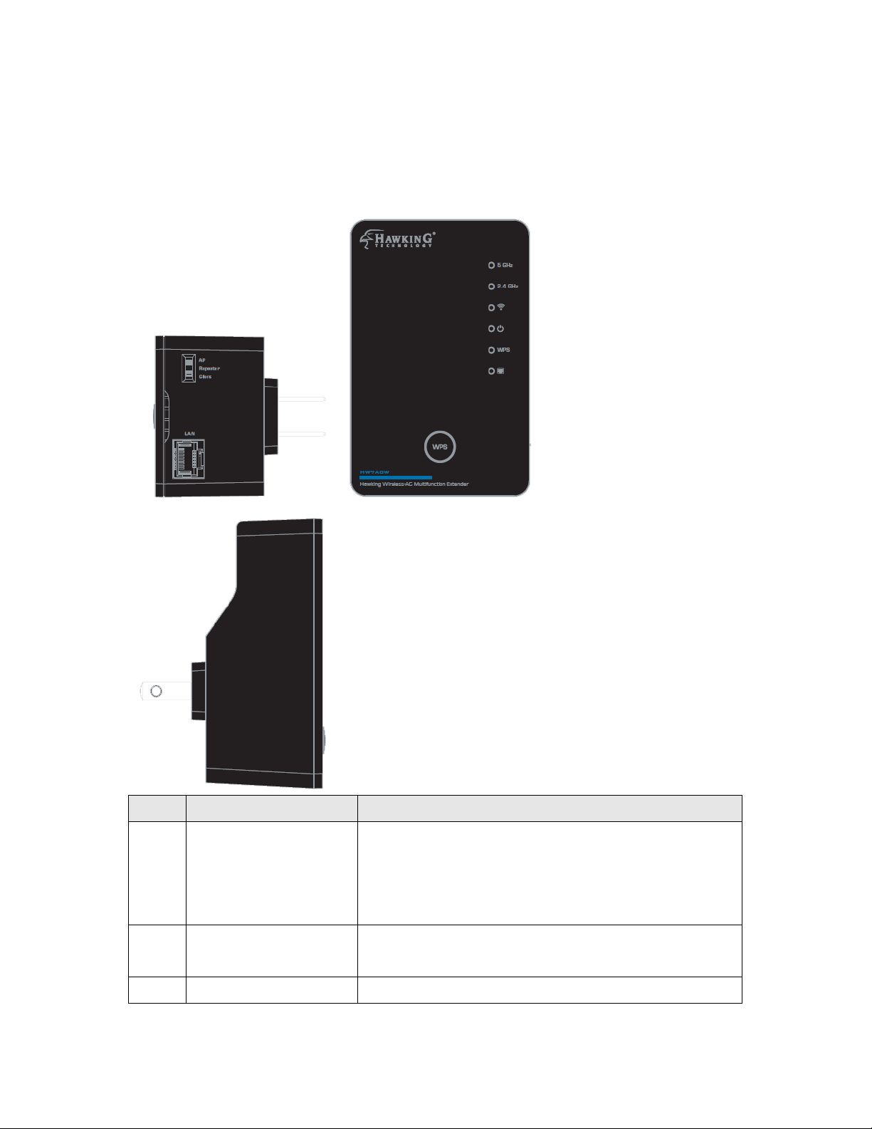
1-6 Product Overview
Item
Item Name
Description
A
Mode switch
You can switch the operation mode by this
switch. The HW7ACW supports 3 modes:
AP mode, Repeater mode and Bridge-Client
mode.
B
LAN port
One 10/100Mbps Ethernet LAN Port with
Auto-MDI/MDI-X.
C
WPS / Reset
This button support 2 functions:
A B C
Interface Descriptions
7
Page 15
button
1. One click to start WPS function (Both
2.4Ghz and 5Ghz)
2. Hold the button 10 seconds to reset all the
values to the factory default.
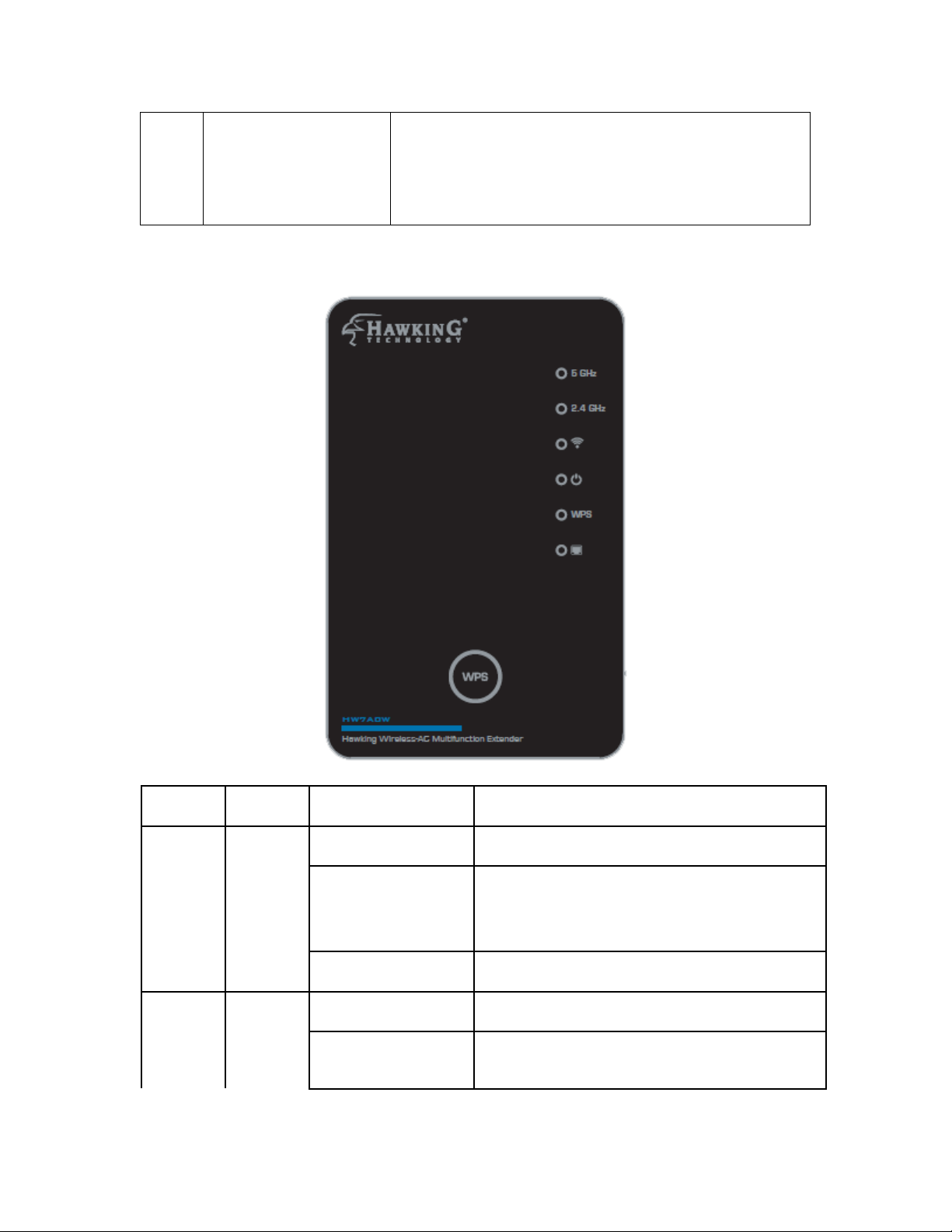
LED
Color
LED Status
Description
Signal
Status
(5G)
Amber
Steady ON
1. Good signal (RSSI 100%~50%)
Blinking
1. Poor signal
2. Slow blinking (RSSI <50%~25%)
3. Quick blinking (RSSI <25%)
Off
1. No signal/ or LED off mode.
Signal
Status
(2.4G)
Green
Steady ON
1. Good signal (RSSI 100%~50%)
Blinking
1. Poor signal
2. Slow blinking (RSSI <50%~25%)
LED Definitions
8
Page 16

3. Quick blinking (RSSI <25%)
Off
1. No signal/ or LED off mode.
WLAN
Status
Green
Blinking
Wireless function is active (transferring
or receiving data)
Off
Wireless network is switched off/ or
LED off mode.
Power
On/Off
Status
Green
Steady ON
1. Power is turned on
Slow Blinking
1. System is booting up.
(Duty cycle 700ms on/700ms off)
2. Ready for “Reset to factory
default”, power LED is blinking.
(Duty cycle 700ms on/700ms off)
Off
1. Power is turned off.
2. LED off mode. (except power LED
is on, other LEDs are off *)
*If you select to enable “LED OFF
mode”, power LED On/Off depends
on your selection, you can select to
leave only power LED on or turn off
all LEDs including this power LED.
WPS
(2.4/5G)
Green
Steady ON
1. When WPS connection is
successful, turn on for 5 minutes.
Blinking
1. WPS is in progress, blinking for 2
minutes (waiting for WPS
connection)
Quick blinking
1. WPS error, blinking
LAN
Green
Steady ON
1. LAN port is connected.
Blinking
1. LAN port is active (transferring or
receiving data).
Off
1. LAN port is not connected/ or LED
off mode
9
Page 17

10
Page 18
CHAPTER II: Repeater Mode
The HW7ACW is designed with the wireless repeater mode. This mode
allows you to repeat your wireless signal and coverage and help you to solve
wireless dead zones.
This chapter will show you how to quickly install this device by using quick
setup and define the settings on the web based interface.
2-1 Repeater Quick Installation Guide
For first time setup and easy installation, you can move this device close to
the Wireless Broadband Router or Access point you wish to connect to.
After the installation is done and wireless connection is made, you can move
this HW7ACW to the place you wish to use it at. Note that in repeater
mode, this device acts like a wireless relay and should be placed at a
midpoint so it can grab a signal from your router and then rebroadcast it to
your extended location.
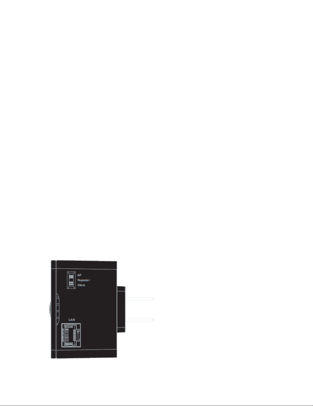
On the Bottom of the product, change the Switch mode selector to
‘Repeater’.
11
Page 19

Insert this device into a power outlet in the wall. You should see ‘Power’
LED light up in a few seconds. If not, please check if the power outlet
you’re using is working.
There are two ways to set this up:
You can build wireless connection via ‘Hardware WPS button’ or ‘Software
web browser’.
If your wireless router or access point supports ‘WPS’, we recommend you
use the WPS button to establish connection. It is the fast and secure way
without computer.
Using WPS button - please go to section 2-1-1
Using Web browser - please go to section 2-1-2
12
Page 20
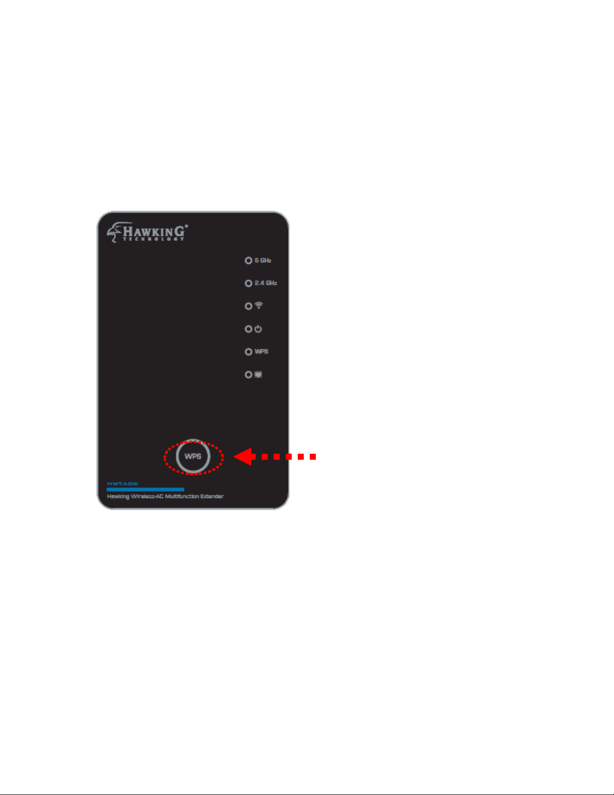
2-1-1 Hardware WPS button setup
WPS button
(1) Press and hold WPS button on HW7ACW for 2 seconds, ‘WPS’ LED
will start flashing.
13
Page 21
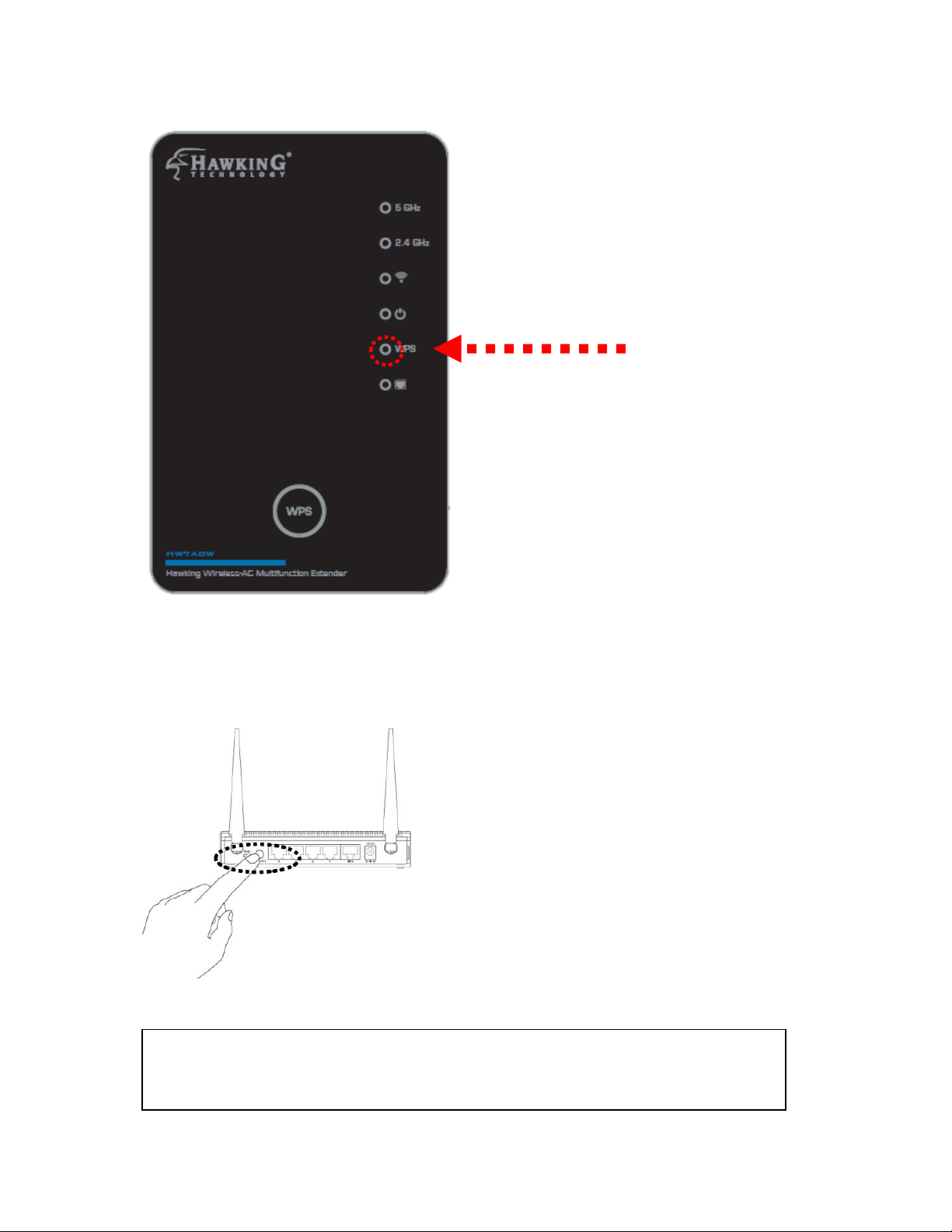
WPS LED
NOTE: this WPS button position on access point is an example.
Different devices may have different WPS button position.
(2) Press WPS button on the wireless broadband router or access point you
wish to connect within 2 minutes.
14
Page 22
TIP: If the access point you wish to connect does not have hardware WPS button,
you can also use its web configuration menu’s WPS function to establish
connection. You can also login to this HW7ACW’s web UI and do the setup there.
(Refer to 2-1-2)
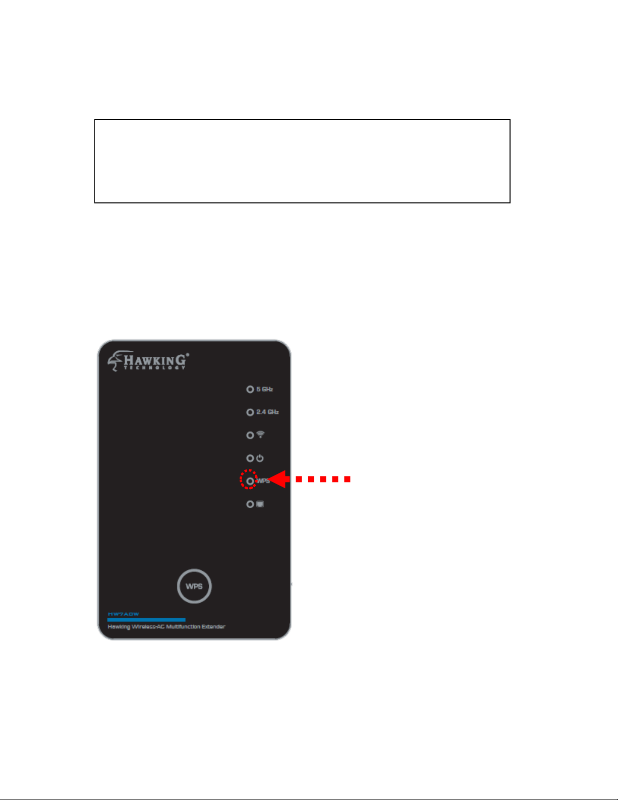
WPS LED
(3) If WPS connection is successfully established, ‘WPS’ LED will light for
5 minutes; if ‘WPS’ LED flashes fast, there’s something wrong. Please wait
for 2 minutes until ‘WPS’ LED off, and try from step 1 again.
When WPS installation is successful, the ‘WLAN” LEDs will turn on.
15
Page 23
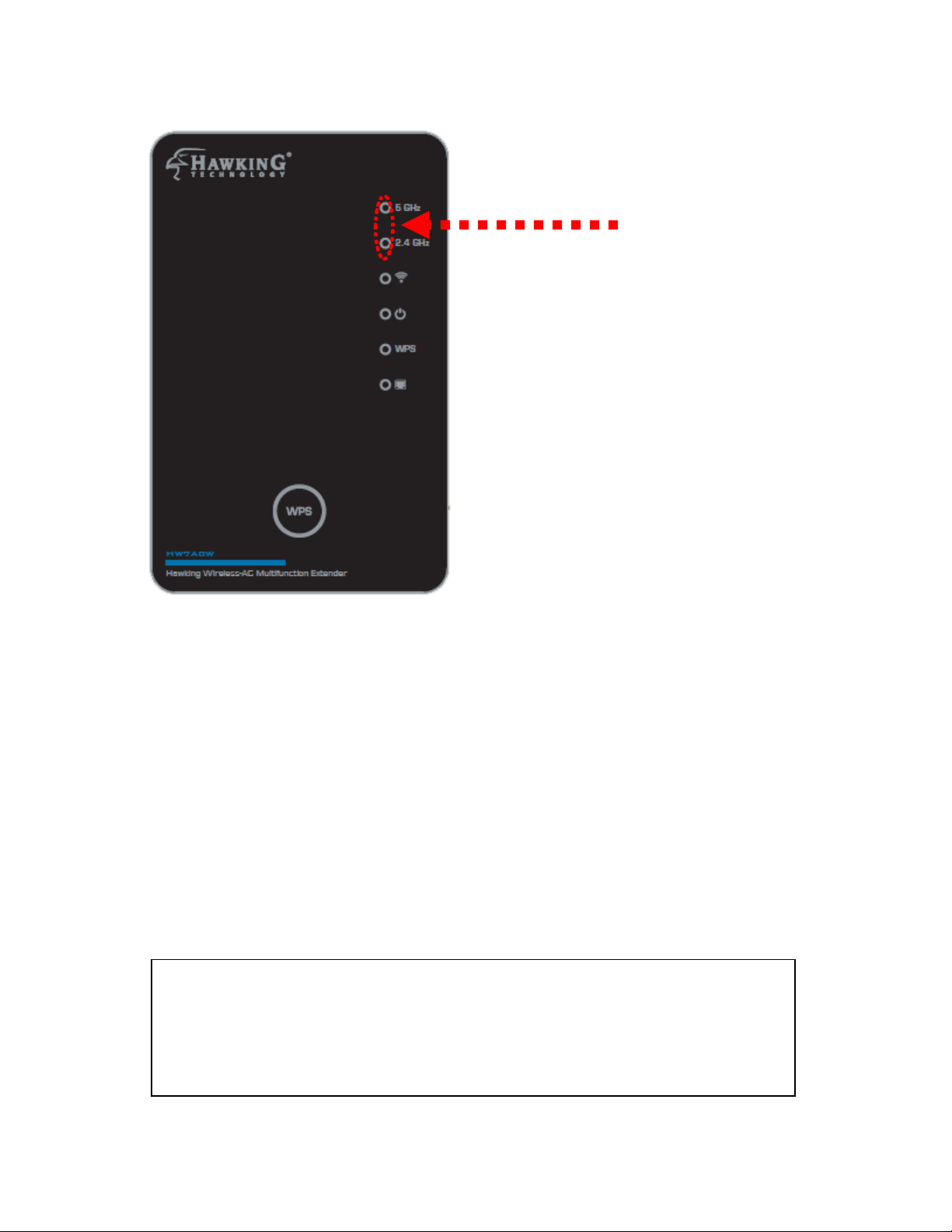
Signal LED
NOTE: If the Signal LED is off, it means the location is out of range of
your wireless broadband router or access point. Please move this
HW7ACW closer to the broadband router until the HW7ACW can
receive signal from broadband router and repeat its signal.
(4) Please move the Wireless HW7ACW to the place you wish to use it (the
best place would be a midpoint between your router and your wireless
devices so the HW7ACW can relay the signal).
You can check the ‘Signal’ LED status to understand signal reception level.
Steady light: Excellent, signal > 67%
Slow Flash: Good, signal < 66%
Quick Flash: Fair, signal < 33%
No Flash: no signal.
16
Page 24
2-1-2 Repeater Web Based Setup
Before you can connect to the HW7ACW and start configuration
procedures, your computer must be able to get an IP address automatically
(use dynamic IP address). If it’s set to use a static IP address, please refer to
‘Chapter V: Appendix, 5-1 Configuring TCP/IP on PC’ to set your computer
to use dynamic IP address.
(1) Use Ethernet cable to connect your computer’s Ethernet port and
wireless HW7ACW’s Ethernet port.
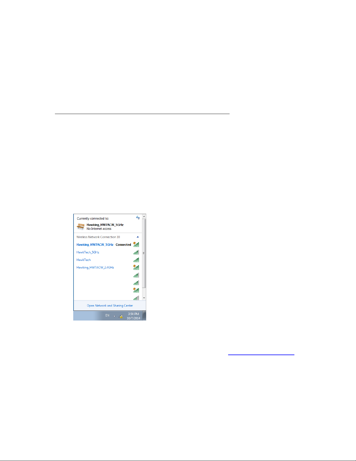
You can also use your computer’s wireless configuration utility to
search for a wireless network called ‘Hawking_HW7ACW and get
connected. (The default 2.4GHz wireless name of this HW7ACW
device is: ‘Hawking_HW7ACW_2.4GHz’ and the default 5GHz
wireless name is ‘Hawking_HW7ACW_5GHz’)
(2) Open a web browser and it should automatically redirect to the setup
page. However, if it does not, you can type in ‘http://repeater.setup’
in the address bar. Note: You can also type in http://192.168.1.241 in
the address bar. A window will prompt you to input username and
password. Default username is ‘admin’ and password is ‘1234’. Click
‘OK’ button to continue.
17
Page 25
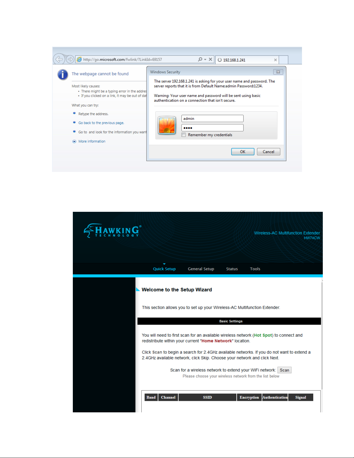
(3) Once you are logged in, the HW7ACW setup page will appear.
18
Page 26
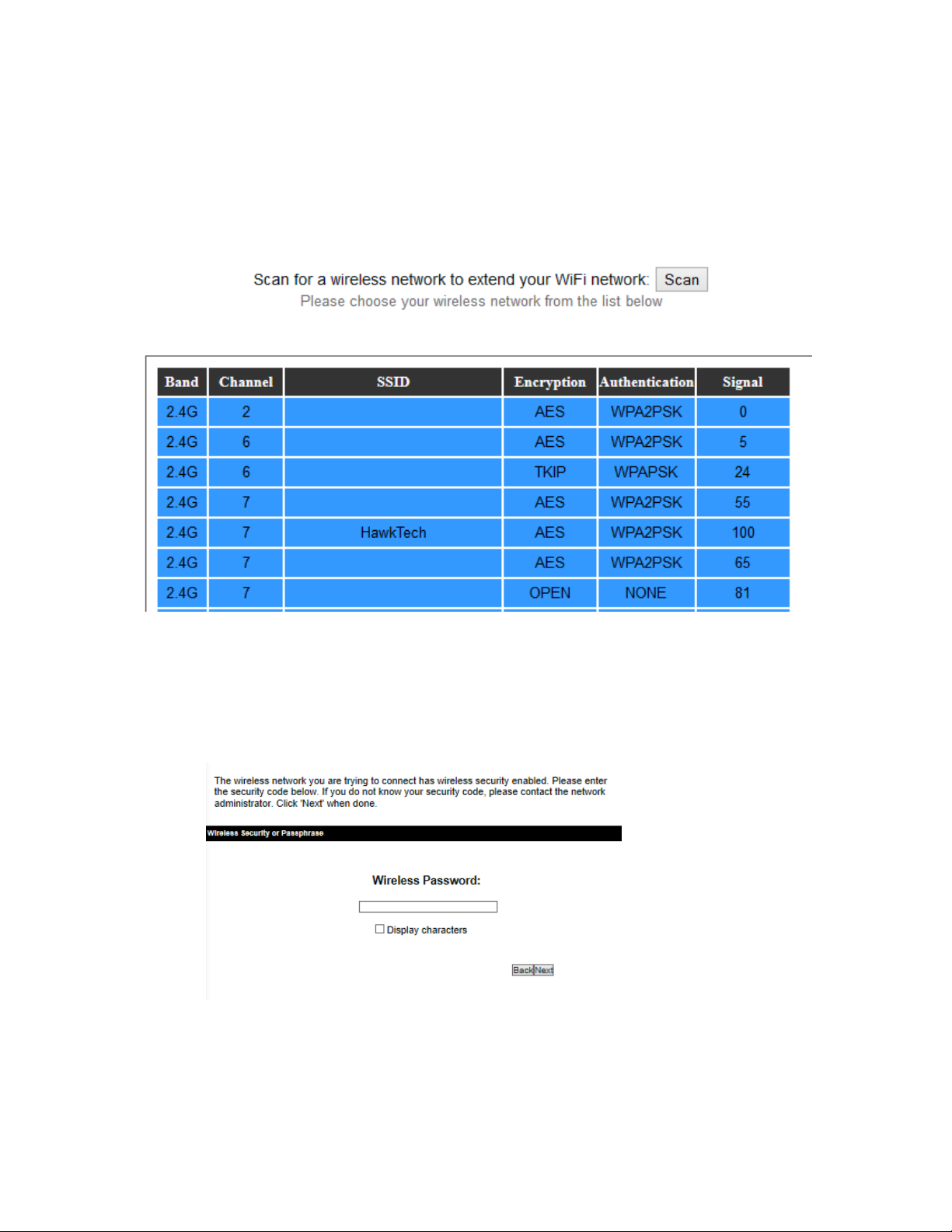
(4) By default, the first page will allow you to choose a 2.4GHz network
you want to connect. If you do not want to repeat a 2.4GHz
network, you can click skip on the bottom of the page. Select your
network and click ‘Next’
(5) If your network is a secure network, a password field will be
prompted. Please type in the wireless password of the 2.4GHz
network. Contact your network admin if you do not know this
password.
Click Next. The device will then verify if you inputted the correct
password. Click Yes to continue if you wish to repeat a 5GHz signal.
19
Page 27
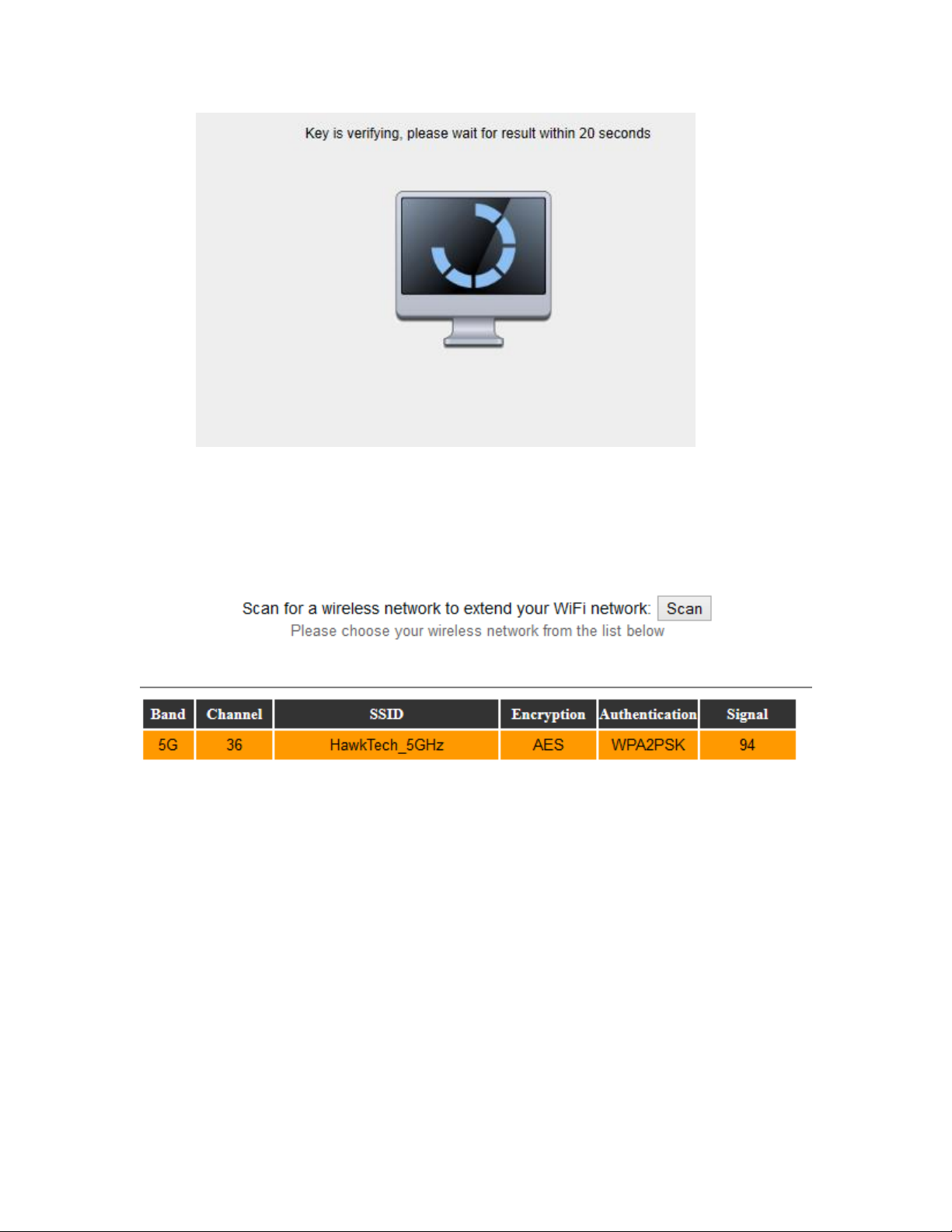
(6) The next page will allow you to choose a 5GHz network you want to
connect. If you do not want to repeat a 5GHz network, you can click
skip on the bottom of the page. Select your network and click ‘Next’
(7) If your network is a secure network, a password field will be
prompted. Please type in the wireless password of the 5GHz
network. Contact your network admin if you do not know this
password.
20
Page 28
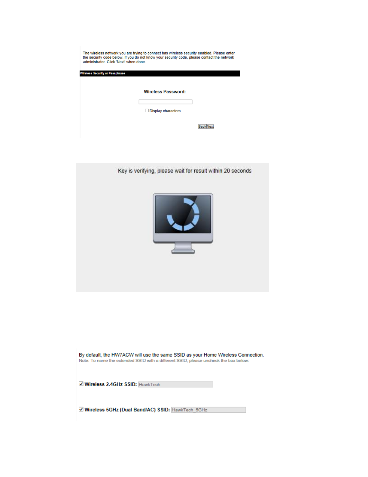
Click Next. The device will then verify if you inputted the correct
password.
Click Next to continue if you wish to repeat a 5GHz signal.
(8) By default, the HW7ACW will use the same SSID as your Home
Wireless Network. If you wish to use a different name, you can
uncheck the box and type in your own SSID.
21
Page 29
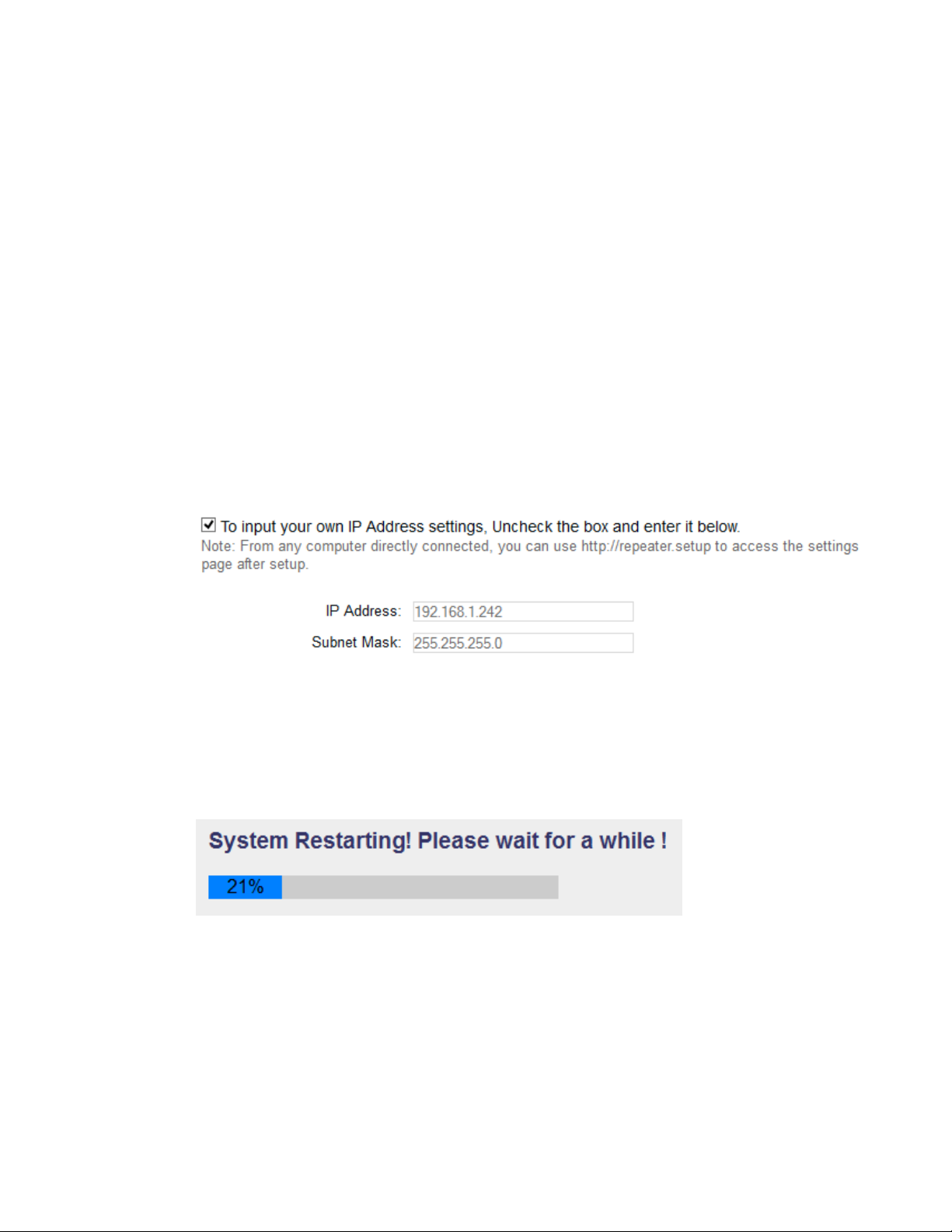
(9) Advanced IP address settings: This section allows you to set an IP
Address and subnet mask to fit your network if needed. Uncheck the
box to input. Otherwise, the default IP Address in repeater mode is
192.168.1.241.
Note1: It is recommended you give it an IP address in the same range
of your network. Otherwise, once it is configured it will not be in
the same range and you will not be able to access the setup page to
view the general settings.
Note2: After configuration, you can access the settings page at any
time using ‘http://repeater.setup’ from any computer that is wirelessly
or directly connected to the HW7ACW. From other devices on the
network,you must use the IP address of the HW7ACW.
(10) The last page wil be a summary of your settings.
If everything is correct, click ‘Finish’ and the HW7ACW will then
proceed to reboot and restart.
(11) After reboot is complete, you can close the web browser to finish
this quick setup. The HW7ACW will now be in extender mode.
Please place the extender in an optimal location.
22
Page 30
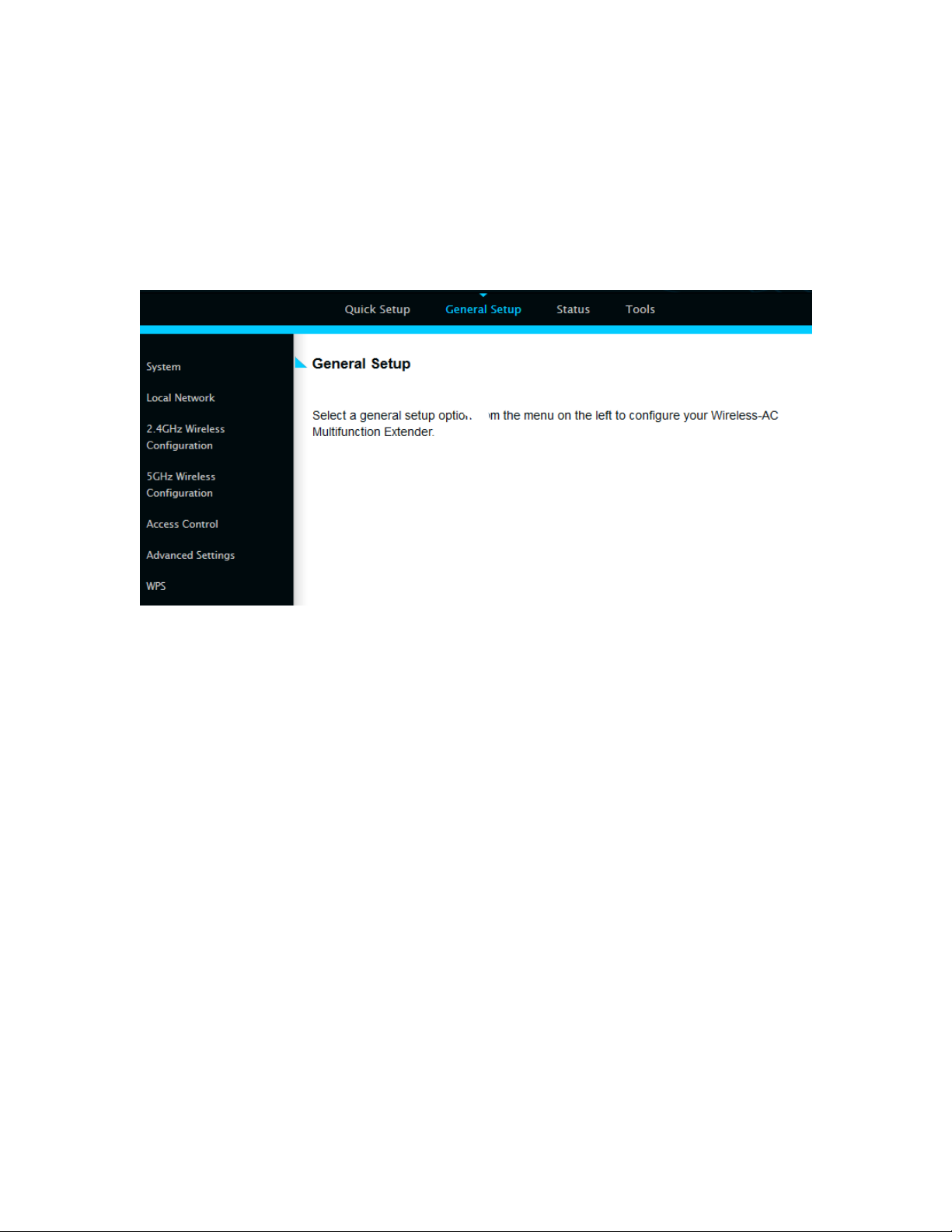
2-2 General Setup
In this chapter, you’ll know how to change the major settings of the
HW7ACW. Log onto the device and click on ‘General Setup’.
2-2-1 System
Change password
Default password of the HW7ACW is ‘1234’, and it’s displayed on the login
prompt when accessed from the web browser. There’s a security risk if you
don’t change the default password, since everyone can see it at the prompt.
This is very important when you have wireless function enabled.
To change password, please follow the instructions:
Please click ‘General Setup’ at top of web management interface, select
‘System’ tab on the left hand column, and then click ‘Password Settings’,
and the following message will be displayed on your web browser:
23
Page 31

1
2
3
Current Please input current password here.
Password (1):
New Password (2): Please input new password here.
Confirm Please input new password here again.
Password (3):
If the password you typed in ‘New Password’ (2) and ‘Confirm Password’
(3) field are not the same, you’ll see the following message:
Please retype the new password again when you see above message.
24
Page 32

If you see the following message:
It means the content in ‘Current Password’ field is wrong, please click ‘OK’
to go back to previous menu, and try to input current password again.
If the current and new passwords are correctly entered, after you click
‘Apply’, you’ll be prompted to input your new password:
Please use new password to enter web management interface again, and you
should be able to login with new password.
25
Page 33

2-2-2 Local Network
Before all computers using wired Ethernet connection can communicate
with each other and access Internet, they must have a valid IP address.
There are two ways to assign IP addresses to computers: static IP address
(set the IP address for every computer manually), and dynamic IP address
(IP address of computers will be assigned by access point automatically. It’s
recommended for most computers to use dynamic IP address, it will save a
lot of time on setting IP addresses for every computer, especially when there
are a lot of computers in your network; for servers and network devices
which will provide services to other computers and users that come from the
Internet, a static IP address should be used.
26
Page 34

Suggestions on IP Address numbering plan:
If you have no idea on how to define an IP address plan for your
network, here are some suggestions.
1. A valid IP address has 4 fields: a.b.c.d, for most of home and
company users, it’s suggested to use 192.168.c.d, where c is
an integer between 0 and 254, and d is an integer between 1
and 254. This router is capable to work with up to 253 clients,
so you can set ‘d’ field of IP address of router as 1 or 254 (or
any number between 1 and 254), and pick a number between
0 and 254 for field ‘c’.
2. In most cases, you should use ‘255.255.255.0’ as subnet
mask, which allows up to 253 clients (this also meets router’s
capability of working with up to 253 clients).
3. For all servers and network devices which will provide
services to other people (like Internet service, print service,
and file service), they should use static IP address. Give each
of them a unique number between 1 and 253, and maintain a
list, so everyone can locate those servers easily.
4. For computers which are not dedicated to provide specific
service to others, they should use dynamic IP address.
1 3 2
4
Please click ‘General Setup’ at the top of web management interface and
click ‘Local Network’ on the left hand column.
There are two setup groups here: ‘LAN IP’ and ‘DHCP Server’
Obtain an IP address (1): The device will automatically obtain an IP
automatically address from your router/network automatically
27
Page 35

Use the Following IP (2):Please input the IP address you wish to use
Recommended Value if you don’t know what to fill:
IP Address: 192.168.1.241
Subnet Mask: 255.255.255.0
Gateway Address: (leave it blank)
1
3 4 2
5
6
Address
Subnet Mask (3): Please input your subnet mask address for the network.
Default Gateway (4): Please input your default gateway for the network
These settings are only available when ‘DHCP Server’ is ‘Enabled’.
Default Gateway (1): Please input your default gateway address
Domain Name (2): If you wish, you can also optionally input the
domain name for your network. This is optional.
DHCP Client Start IP (3): Please input the start IP address of the IP range.
DHCP Client End IP (4): Please input the end IP address of the IP range.
28
Page 36

Domain Name (5): If you wish, you can also optionally input the domain
Recommended Value if you don’t know what to fill:
Lease Time: Two Weeks (or ‘Forever’, if you have less than 20 computers)
Default Gateway: (leave it blank)
Domain Server IP: (leave it blank)
Start IP: 192.168.1.100
End IP: 192.168.1.200
Domain Name: (leave it blank)
NOTE:
1. The number of the last field (mentioned ‘d’ field) of ‘End IP’ must be
greater than ‘Start IP’, and cannot be the same as router’s IP address.
2. The former three fields of IP address of ‘Start IP’, ‘End IP’, and ‘IP
Address of ‘LAN IP’ section (mentioned ‘a’, ‘b’, and ‘c’ field) should be the same.
3. These settings will affect wireless clients too.
name for your network. This is optional.
Lease Time (6): Please choose a lease time (the duration that every
computer can keep a specific IP address) of every IP
address assigned by this access point from dropdown
menu.
2-2-3 Wireless Configuration
Please click ‘General Setup’ tab at the top of web management interface, and
then click ‘2.4GHz Wireless Configuration’ or 5GHz Wireless Configuration
tab on the left hand column. The following message will be displayed on
your web browser:
29
Page 37

SSID (3): This is the name of wireless network that the HW7ACW
will broadcast.
Channel (4): This is the wireless channel that the HW7ACW will
broadcast at. Please make sure it is the same channel
of the existing network you hope to repeat.
2-2-3-1 Security Settings
It is important to set your wireless security settings properly! In repeater
mode, the security settings must match the wireless network you are
planning to connect to, otherwise, a connection cannot be established.
Please select an encryption method from the ‘Encryption’ dropdown menu,
there are four options:
Disable
WEP
WPA pre-shared key
30
Page 38

Disable wireless security
2
3
6
4
5
When you select this mode, data encryption is disabled.
Use this option only when there is no security set up on the original
Wireless Signal.
WEP - Wired Equivalent Privacy
When you select this mode, the wireless access point will use WEP
encryption, and the following setup menu will be shown on your web
browser:
Key Length (2): There are two types of WEP key length: 64-bit and
128-bit. Using ‘128-bit’ is safer than ’64-bit’, but will
reduce some data transfer performance.
Key Format (3): There are two types of key format: ASCII and Hex.
When you select a key format, the number of
characters of key will be displayed. For example, if you
select ’64-bit’ as key length, and ‘Hex’ as key format,
you’ll see the message at the right of ‘Key Format’ is ‘Hex
(10 characters), which means the length of WEP key is 10
31
Page 39

characters.
TIPS: Examples of WEP key
ASCII (5 characters): pilot phone 23561 2Hyux #@xmL
ASCII (13 characters): digitalFAMILY 82Jh26xHy3m&n
Hex (10 characters): 287d2aa732 1152dabc85
Hex (26 characters): 9284bcda8427c9e036f7abcd84
To improve security level, do not use words that can be found in a dictionary or are
easy to remember! Wireless clients will automatically remember the WEP key, so you
only have to input the WEP key on wireless client once, and it is suggested that to use
a complex WEP key to improve security level. Once you have chosen a password,
write it down and keep it in a secure place.
Default Tx Key (4): This device only supports one WEP Key ‘Key 1’.
Encryption Key (5) Input WEP key characters here, the number of
characters must be the same as the number displayed
at ‘Key Format’ field. You can use any alphanumerical
characters (0-9, a-z, and A-Z) if you select ‘ASCII’ key
format, and if you select ‘Hex’ as key format, you can
use characters 0-9, a-f, and A-F. You must enter at
least one encryption key here, and if you entered
multiple WEP keys, they should not be same with each
other.
After you finish WEP setting, please click ‘Apply’ (6) button and the
following message will be displayed on your web browser:
32
Page 40

Please click ‘Go Back’ to go back to previous setup menu, or click ‘Apply’
2
3
5
4
to reboot the access point so the settings will take effect. Please wait 30-60
seconds for the access point to reboot.
Wi-Fi Protected Access (WPA):
When you select this mode, the wireless access point will use WPA
encryption, and the following setup menu will be shown on your web
browser:
WPA Unicast Please select a type of WPA cipher suite.
Cipher Suite (2): Available options are: WPA (TKIP), WPA2 (AES), and
You can select one of them, but you have to make sure
your wireless client support the cipher you selected.
Pre-shared Select the type of pre-shared key, you
Key Format (3): can select Passphrase (8 or more alphanumerical
characters, up to 63), or Hex (64 characters of 0-9,
and a-f).
Pre-shared Please input the WPA passphrase here.
Key (4): It’s not recommended to use a word that can be found
in a dictionary due to security reason.
After you finish WPA Pre-shared key setting, please click ‘Apply’ button (5)
and the following message will be displayed on your web browser:
33
Page 41

NOTE: Some wireless clients (especially those manufactured before
year 2003) only support WEP or WPA (TKIP) cipher. A driver upgrade
would be needed for those clients to use WPA and WPA2 encryption.
Please click ‘Go Back’ to go back to previous setup menu, or click ‘Apply’
to reboot the access point so the settings will take effect. Please wait 30-60
seconds for the access point to reboot.
34
Page 42

2-2-4 Wireless Access Control
1
2
3
6
7
4
This function will help you prevent unauthorized users from connecting to
your wireless access point; only those wireless devices who have a MAC
address you assigned can gain access to your wireless access point. Use this
function with other security measures described in previous section, to create
a safer wireless environment.
You can add up to 20 MAC addresses by using this function. Please click
‘General Setup’ at the top of web management interface and click ‘Wireless
Configuration’ on the left hand column. Select ‘Access Control’.
35
Page 43

All allowed MAC addresses will be displayed in ‘MAC Address Filtering
Table.
Enable Wireless To enforce MAC address filtering, you have to check
Access Control (1): ‘Enable Wireless Access Control’. When this item is
unchecked, wireless access point will not enforce MAC
address filtering of wireless clients.
MAC Address (2): Input the MAC address of your wireless devices here,
dash ( - ) or colon ( : ) are not required. (i.e. If the
MAC address label of your wireless device indicates
‘aa-bb-cc-dd-ee-ff’ or ‘aa:bb:cc:dd:ee:ff’, just input
‘aabbccddeeff’.
Comment (3): You can input any text here as the comment of this
MAC address, like ‘ROOM 2A Computer’ or
anything. You can input up to 16 alphanumerical
characters here. This is optional and you can leave
it blank, however, it’s recommended to use this field
to write a comment for every MAC addresses as a
memory aid.
Add (4): Click ‘Apply’ button to add the MAC address and
associated comment to the MAC address filtering table.
Clear (5): Click ‘Clear’ to remove the value you inputted in
MAC address and comment field.
Delete Selected (6): If you want to delete a specific MAC address entry,
check the ‘select’ box of the MAC address you want to
delete, then click ‘Delete Selected’ button. (You can
select more than one MAC addresses).
Delete All (7): If you want to delete all MAC addresses listed
36
Page 44

here, please click ‘Delete All’ button.
After you finish with all settings, please click ‘Apply’ (8) button and the
following message will be displayed on your web browser:
Please click ‘Go Back’ to go back to previous setup menu, or click ‘Apply’
to reboot the access point so the settings will take effect. Please wait 30-60
seconds for the access point to reboot.
37
Page 45

2-2-5 Advanced Wireless Settings
1
2
3
4
5
7
8
6
9
10
11
12
This bridge provides some advanced control of wireless parameters, if you
want to configure these settings, please click ‘General Setup’ at the top of
web management interface and click ‘Advanced Settings’ on the left hand
column.
Fragment Threshold(1): Set the Fragment threshold of wireless radio.
Do not modify the default value if you do not
understand the function, default value is ‘2346’.
38
Page 46

RTS Threshold(2): Set the RTS threshold of wireless radio. Do not modify
the default value if you do not understand the
function, default value is ‘2347’.
Beacon Interval(3): Set the beacon interval of wireless radio. Do not
modify the default value if you do not understand the
function, default value is ‘100’.
DTIM Period(4): Set the DTIM period of wireless radio. Do not modify
the
default value if you do
not understand the
function
, default value is ‘3’.
Data Rate(5): Set the wireless data transfer rate to a certain value.
Since most of wireless devices will negotiate with each
other and pick a proper data transfer rate
automatically. It is not necessary to change this value
unless you know what will happen after modification.
N Data Rate(6): Same as above, but only for 802.11n clients.
Channel Width(7): Set channel width of wireless radio. Do not modify the
default value if you do not understand the function,
default setting is ‘Auto 80 MHz’.
Preamble Type(8): Set the type of preamble, do not modify the default
value if you do not know what it is, default setting is
‘Short Preamble’.
Broadcast ESSID(9): Decide if the wireless access point will broadcast its
own ESSID or not. You can hide the ESSID of your
wireless access point (set the option to ‘Disable’), so
only those people who know the ESSID of your
wireless access point can connect to the unit.
CTS Protect(10): Enabling this setting will reduce the chance of radio
39
Page 47

signal collisions between 802.11b and 802.11g/n
wireless access points. It is recommended to set this
option to ‘Auto’ or ‘Always’. However, if you set to
‘None’, your wireless access point should be able to
function properly.
Transmit Power(11): You can set the output power of wireless radio. Unless
you are using this wireless access point in a large open
space, you may not have to set output power to 100%.
This will enhance security (malicious / unauthorized
users in distance will not be able to reach your
wireless access point).
WMM(12): Wi-Fi MultiMedia (WMM) will enhance the data
transfer performance of multimedia contents when they
are being transferred over a wireless network. If you
do not understand the function, then it is safe to set
this option to ‘Enable’, however, default value is
‘Disable’.
After you finish these wireless settings, please click ‘Apply’ button, button,
and the following message will be displayed on your web browser:
40
Page 48

Please click ‘Go Back’ to go back to previous setup menu; to continue on
access point setup, or click ‘Apply’ to reboot the access point so the settings
will take effect. Please wait 30-60 seconds for the access point to reboot.
41
Page 49

2-2-6 Wi-Fi Protected Setup (WPS)
Wi-Fi Protected Setup (WPS) is the simplest way to build connection
between wireless network clients and this wireless access point. You don’t
have to select an encryption mode and input a long encryption passphrase
every time when you need to set up a wireless client, you only have to press
a button on the wireless client and this wireless access point, and the WPS
will automatically configure for you.
This wireless access point supports two types of WPS: Push-Button
Configuration (PBC), and PIN code. If you want to use PBC, you have to
push a specific button on the wireless client to start WPS mode, and switch
this wireless access point to WPS mode too. You can push Reset/WPS
button of this wireless access point, or click ‘Start PBC’ button in the web
configuration interface to do this; if you want to use PIN code, you have to
know the PIN code of wireless client and switch it to WPS mode, then
provide the PIN code of the wireless client you wish to connect to this
wireless access point. The detailed instructions are listed follow:
Please click ‘General Setup’ at the top of web management interface and
click ‘Wireless Configuration’ on the left hand column. Select ‘WPS’.
42
Page 50

1
3
4
5
Enable WPS (1) Check this box to enable WPS function, uncheck it to
disable WPS.
WPS Information (2) WPS Status: If the wireless security (encryption)
function of this wireless access point is properly set,
you’ll see ‘Configured’ message here. If wireless
security function has not been set, you’ll see ‘Not
configured’.
Self PIN code: This is the WPS PIN code of this
wireless access point. This code is useful when you
need to build wireless connection by WPS with other
WPS-enabled wireless devices.
43
Page 51

SSID: The SSID of this wireless access point will be
displayed here.
Authentication Mode: The wireless security
authentication mode of this wireless access point will
be displayed here. If you do not enable security
function of the wireless access point before WPS is
activated, the access point will auto set the security to
WPA (AES) and generate a set passphrase key for WPS
connection.
Passphrase Key: The wireless security key of the
access point will be displayed here.
Config Mode (3) There are ‘Registrar’ and ‘Enrollee’ modes for the
WPS connection. When ‘Registrar’ is enabled, the
wireless clients will follow the access point’s wireless
settings for WPS connection. When ‘Enrolle’ mode is
enabled, the access point will follow the wireless
settings of wireless client for WPS connection.
Configure Click ‘Start PBC’ to start Push-Button style WPS
by Push Button (4) setup procedure. This wireless access point will wait
for WPS requests from wireless clients for 2 minutes.
The ‘WLAN’ LED light on the wireless access point
will be steady for 2 minutes when this wireless access
point is waiting for incoming WPS request.
Input client Please input the PIN code of the wireless client you
PinCode (5) wish to connect, and click ‘Start PIN’ button.
The ‘WLAN’ LED light on the wireless access point
will be steady when this wireless access point is
waiting for incoming WPS request.
44
Page 52

2-3 Status
The status and information of the HW7ACW will be displayed here.
Click on the status tab on the top of web page.
You should see the screen looks like this (the contents will vary depending
on your current firmware):
45
Page 53

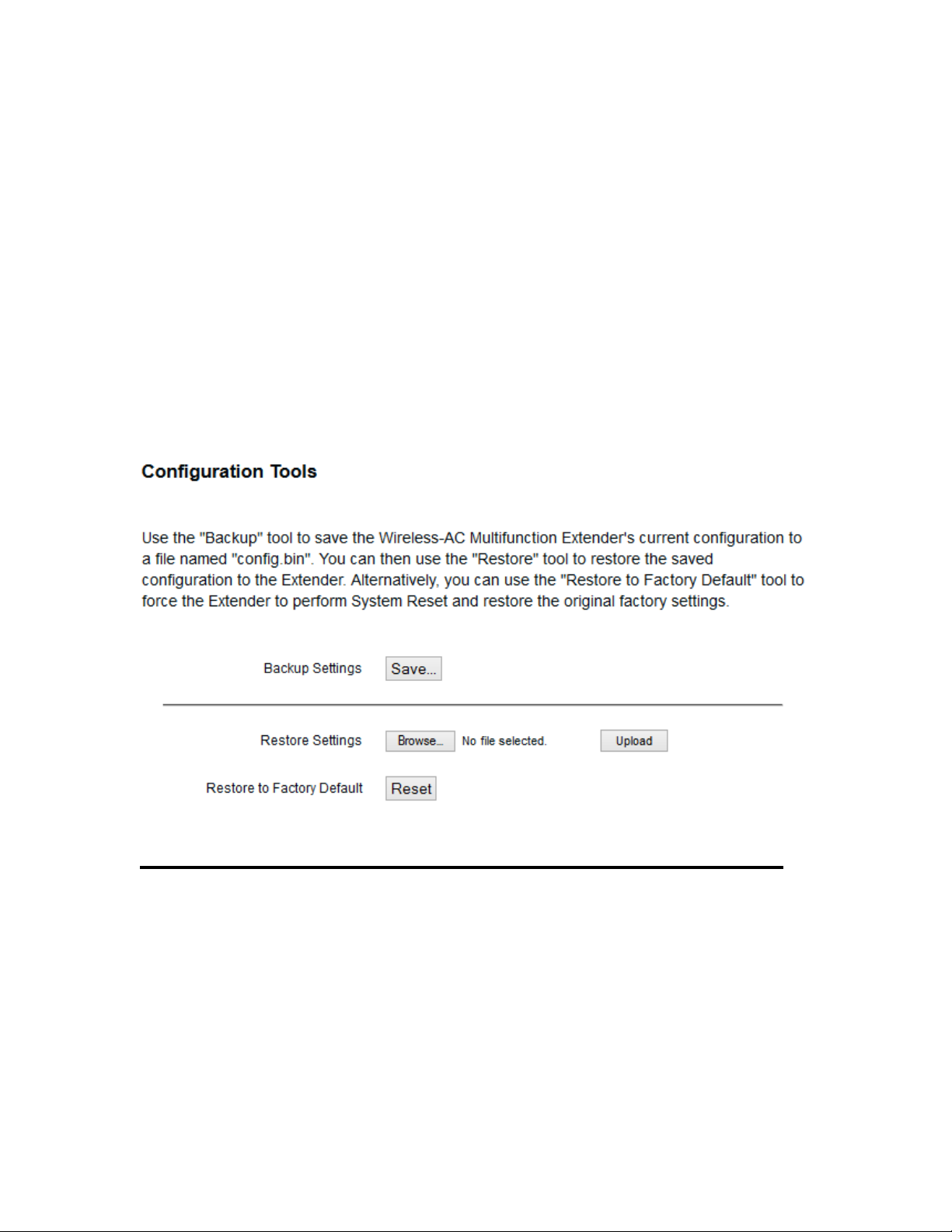
2-4 Configuration Tools
1 2 3
You can back up all configurations of this access point to a file, so you can
make several cops of the HW7ACW’s configuration for security reason.
To backup or restore the HW7ACW’s configuration, please follow the
instructions:
Please click ‘Tools’ menu at the top of web management interface, and then
click ‘Configuration Tools’ on the left hand column.
Backup Press ‘Save...’ button, and you’ll be prompted to
Settings (1): download the configuration as a file, default filename
is ‘default.bin’, you can please save it as another
filename for different versions, and keep it in a safe
place.
Restore Press ‘Browse…’ to pick a previously-saved
Settings (2): configuration file from your computer, and then click
46
Page 54

‘Upload’ to transfer the configuration file to access
point. After the configuration is uploaded, the access
point’s configuration will be replaced by the file you
just uploaded.
Restore to Click this button to remove all settings you made, and
Factory Default (3): restore the configuration of this access point back to
factory default settings.
47
Page 55

2-5 Firmware Upgrade
The system software used by this access point is known as ‘firmware’, just
like any applications on your computer, when you replace the old application
with a new one; your computer will be equipped with new function. You can
also use this firmware upgrade function to add new functions to your access
point, even fix the bugs of this access point.
To upgrade firmware, please follow the instructions:
Please click ‘Tools’ menu at the top of web management interface, and then
click ‘Firmware Upgrade’ on the left hand column.
Click ‘Next’ button if you wish to upgrade your firmware.
48
Page 56

NOTE: Never interrupt the upgrade procedure by closing the web
browser or physically disconnect your computer from router. If the
firmware you uploaded is corrupt, the firmware upgrade will fail, and
you may have to return this router to the dealer of purchase to ask
for help. Warranty is void if you interrupt the upgrade procedure.
Click ‘Browse’ button, and you’ll be prompted to provide the filename of the
firmware upgrade file. Please download the latest firmware file from the
Hawking Technologies website at www.hawkingtech.com, and use it to
upgrade your access point.
After a firmware upgrade file is selected, click ‘Apply’ button, and the
access point will start firmware upgrade procedure automatically. The
procedure may take several minutes, please be patient.
49
Page 57

2-6 System Reset
If you think you network performance is bad, or you find the behavior of the
access point is strange, you can perform a access point reset. Sometimes it
will solve the problem.
Please click ‘Tools’ menu at the top of web management interface, and then
click ‘Reset on the left hand column.
Please click ‘Apply’ to reset your access point, and it will be available again
after a few minutes, please be patient.
50
Page 58

CHAPTER III: Bridge Mode
Client mode can let your networking device have wireless capability; it will
become your device’s wireless network card. You can connect this device to
an Ethernet port on a TV or DVD player or game console device with
Ethernet cable.
This chapter will show you how to quickly install this device by using quick
setup and show you the each detailed setting on web UI page of client mode.
3-1 Client Bridge Quick Installation Guide
Switch mode selector to ‘Client’.
Insert this device into power outlet on the wall. You should see ‘Power’ LED
light up in few seconds. If not, please check if the power outlet you’re using
is working.
Connect your wired networking device (wired PC, or internet TV, or game
console, etc.) and this device by Ethernet cable.
51
Page 59

NOTE: You must set your networking device as DHCP client (obtain IP
automatically from DHCP server)
You can build wireless connection via ‘Hardware WPS button’ or ‘Software
web browser’.
If your wireless router or access point supports ‘WPS’, we recommend you
use the WPS button to establish connection. It is the fast and secure way
without computer.
Using WPS button - please go to section 3-1-1
Using Web browser - please go to section 3-1-2
52
Page 60

3-1-1 Hardware WPS button setup
WPS button
(1) Press and hold WPS button on the HW7ACW for 2 seconds. The
‘WPS’ LED will start flashing.
53
Page 61

WPS LED
(2) Press the WPS button on the wireless broadband router or access point
you wish to connect within 2 minutes.
54
Page 62

NOTE: Different devices will have different WPS button positions.
TIP: If the access point you wish to connect does not have hardware WPS button,
you can also use its web configuration menu’s WPS function to establish
connection. You can also log into the HW7ACW’s web UI to do a quick setup.
(refer. to section 3-1-2)
WPS LED
(3) If WPS connection is successfully established, the ‘WPS’ LED will light
for 5 minutes; if the ‘WPS’ LED flashes fast, there’s something wrong.
Please wait for 2 minutes until ‘WPS’ LED is off and try from step 1 again.
When WPS installation is successful, ‘WLAN” LED will turn on.
55
Page 63

Signal LED
NOTE: If the Signal LED is off, it means the location is out of range of
your wireless broadband router or access point. Please move this
HW7ACW closer to the wireless signal until the HW7ACW can receive
signal from broadband router and bridge the signal.
You can check the ‘Signal’ LED status to understand signal reception level.
Steady light: Excellent, signal > 67%
Slow Flash: Good, signal < 66%
Quick Flash: Fair, signal < 33%
No Flash: no signal.
56
Page 64

3-1-2 Client Bridge Web based Setup
Before you connect to the H7ACW and start configuration procedures, your
computer must be able to get an IP address automatically (use dynamic IP
address). If it’s set to use static IP address, or you’re unsure, please refer to
‘Chapter 5-1 Configuring TCP/IP on PC’ to set your computer to use
dynamic IP address.
(1) Use an Ethernet cable to connect your computer’s Ethernet port and
HW7ACW’s Ethernet port.
(2) Open a web browser and it should automatically redirect to the setup
page. However, if it does not, you can type ‘http://repeater.setup’ in
address bar. Note: You can also type ‘http://192.168.1.242’ in the
address bar. A window will prompt you to input username and
password. Default username is ‘admin’ and password is ‘1234’. Click
‘OK’ button to continue.
57
Page 65

(3) Once you are logged in, the HW7ACW setup page will appear.
(4) Click on “Select Site Survey” to choose the wireless network you
wish to bridge to.
58
Page 66

Select your network and click ‘Done’. The SSID field should be
filled in with the network name you selected.
(5) Advanced IP address settings: This section allows you to set an IP
Address and subnet mask to fit your network if needed. Uncheck the
box to input. Otherwise, the default IP Address in Bridge Mode is
192.168.1.242.
Note1: It is recommended you give it an IP address in the same range
of your network. Otherwise, once it is configured it will not be in
the same range and you will not be able to access the setup page to
view the general settings.
Note2: After configuration, you can access the settings page at any
time using ‘http://repeater.setup’ from any computer that is wirelessly
or directly connected to the HW7ACW. From other devices on the
network, they must use the IP address of the HW7ACW.
59
Page 67

(6) After you have selected your wireless network and clicked apply, if
your wireless network you hope to bridge has wireless security, the
next page will prompt you to enter in your security key. Please make
sure you type in the exact key as the wireless network. If you are
unsure what your key is, please contact the wireless router/access
point’s manufacturer or your network adminsitrator. Click ‘Next’
when you’re done.
(7) The system will now verify that your password is correct.
60
Page 68

(8) The last page wil be a summary of your settings. If everything is
correct, click ‘Finish’ and the HW7ACW will then proceed to reboot
and restart.
(9) After reboot complete, you can close the web browser to finish this
quick setup. Connect the HW7ACW via Ethernet cable to the device
you wish to bridge.
61
Page 69

3-2 General Setup
In this chapter, you’ll know how to change the major settings of the
HW7ACW. Log onto the device and click on ‘General Setup’.
3-2-1 System
Change password
Default password of the HW7ACW is ‘1234’, and it’s displayed on the login
prompt when accessed from the web browser. There’s a security risk if you
don’t change the default password, since everyone can see it at the prompt.
This is very important when you have wireless function enabled.
To change password, please follow the instructions:
Please click ‘General Setup’ at top of web management interface, select
‘System’ tab on the left hand column, and then click ‘Password Settings’,
and the following message will be displayed on your web browser:
62
Page 70

1
2
3
Current Please input current password here.
Password (1):
New Password (2): Please input new password here.
Confirm Please input new password here again.
Password (3):
If the password you typed in ‘New Password’ (2) and ‘Confirm Password’
(3) field are not the same, you’ll see the following message:
Please retype the new password again when you see above message.
63
Page 71

If you see the following message:
It means the content in ‘Current Password’ field is wrong, please click ‘OK’
to go back to previous menu, and try to input current password again.
If the current and new passwords are correctly entered, after you click
‘Apply’, you’ll be prompted to input your new password:
Please use new password to enter web management interface again, and you
should be able to login with new password.
64
Page 72

3-2-2 Local Network
Before all computers using wired Ethernet connection can communicate
with each other and access Internet, they must have a valid IP address.
There are two ways to assign IP addresses to computers: static IP address
(set the IP address for every computer manually), and dynamic IP address
(IP address of computers will be assigned by access point automatically. It’s
recommended for most computers to use dynamic IP address, it will save a
lot of time on setting IP addresses for every computer, especially when there
are a lot of computers in your network; for servers and network devices
which will provide services to other computers and users that come from the
Internet, a static IP address should be used.
65
Page 73

Suggestions on IP Address numbering plan:
If you have no idea on how to define an IP address plan for your
network, here are some suggestions.
5. A valid IP address has 4 fields: a.b.c.d, for most of home and
company users, it’s suggested to use 192.168.c.d, where c is
an integer between 0 and 254, and d is an integer between 1
and 254. This router is capable to work with up to 253 clients,
so you can set ‘d’ field of IP address of router as 1 or 254 (or
any number between 1 and 254), and pick a number between
0 and 254 for field ‘c’.
6. In most cases, you should use ‘255.255.255.0’ as subnet
mask, which allows up to 253 clients (this also meets router’s
capability of working with up to 253 clients).
7. For all servers and network devices which will provide
services to other people (like Internet service, print service,
and file service), they should use static IP address. Give each
of them a unique number between 1 and 253, and maintain a
list, so everyone can locate those servers easily.
8. For computers which are not dedicated to provide specific
service to others, they should use dynamic IP address.
1 3 2
4
Please click ‘General Setup’ at the top of web management interface and
click ‘Local Network’ on the left hand column.
There are two setup groups here: ‘LAN IP’ and ‘DHCP Server’
Obtain an IP address (1): The device will automatically obtain an IP
automatically address from your router/network automatically
66
Page 74

Use the Following IP (2):Please input the IP address you wish to use
Recommended Value if you don’t know what to fill:
IP Address: 192.168.1.241
Subnet Mask: 255.255.255.0
Gateway Address: (leave it blank)
1
3 4 2
5
6
Address
Subnet Mask (3): Please input your subnet mask address for the network.
Default Gateway (4): Please input your default gateway for the network
These settings are only available when ‘DHCP Server’ is ‘Enabled’.
Default Gateway (1): Please input your default gateway address
Domain Name (2): If you wish, you can also optionally input the
domain name for your network. This is optional.
DHCP Client Start IP (3): Please input the start IP address of the IP range.
DHCP Client End IP (4): Please input the end IP address of the IP range.
67
Page 75

Domain Name (5): If you wish, you can also optionally input the domain
Recommended Value if you don’t know what to fill:
Lease Time: Two Weeks (or ‘Forever’, if you have less than 20 computers)
Default Gateway: (leave it blank)
Domain Server IP: (leave it blank)
Start IP: 192.168.1.100
End IP: 192.168.1.200
Domain Name: (leave it blank)
NOTE:
1. The number of the last field (mentioned ‘d’ field) of ‘End IP’ must be
greater than ‘Start IP’, and cannot be the same as router’s IP address.
2. The former three fields of IP address of ‘Start IP’, ‘End IP’, and ‘IP
Address of ‘LAN IP’ section (mentioned ‘a’, ‘b’, and ‘c’ field) should be the same.
3. These settings will affect wireless clients too.
name for your network. This is optional.
Lease Time (6): Please choose a lease time (the duration that every
computer can keep a specific IP address) of every IP
address assigned by this access point from dropdown
menu.
3-2-3 Wireless Configuration
Please click ‘General Setup’ tab at the top of web management interface, and
then click ‘2.4GHz Wireless Configuration’ or ‘5GHz Wireless
Configuration’ tab on the left hand column. The following message will be
displayed on your web browser:
68
Page 76

SSID (3): This is the name of wireless network that the HW7ACW
will connect to. You can choose either the 2.4GHz
signal OR the 5GHz signal when setting in client mode.
Channel (4): This is the wireless channel of the network the
HW7ACW is connecting to. It must match the same
settings as the original WiFi access point/router.
3-2-3-1 Security Settings
It is important to set your wireless security settings properly! In repeater
mode, the security settings must match the wireless network you are
planning to connect to, otherwise, a connection cannot be established.
Please select an encryption method from the ‘Encryption’ dropdown menu,
there are four options:
Disable
WEP
WPA pre-shared key
69
Page 77

Disable wireless security
2
3
6
4
5
When you select this mode, data encryption is disabled.
Use this option only when there is no security set up on the original
Wireless Signal.
WEP - Wired Equivalent Privacy
When you select this mode, the wireless access point will use WEP
encryption, and the following setup menu will be shown on your web
browser:
Key Length (2): There are two types of WEP key length: 64-bit and
128-bit. Using ‘128-bit’ is safer than ’64-bit’, but will
reduce some data transfer performance.
Key Format (3): There are two types of key format: ASCII and Hex.
When you select a key format, the number of
characters of key will be displayed. For example, if you
select ’64-bit’ as key length, and ‘Hex’ as key format,
you’ll see the message at the right of ‘Key Format’ is ‘Hex
(10 characters), which means the length of WEP key is 10
70
Page 78

characters.
TIPS: Examples of WEP key
ASCII (5 characters): pilot phone 23561 2Hyux #@xmL
ASCII (13 characters): digitalFAMILY 82Jh26xHy3m&n
Hex (10 characters): 287d2aa732 1152dabc85
Hex (26 characters): 9284bcda8427c9e036f7abcd84
To improve security level, do not use words that can be found in a dictionary or are
easy to remember! Wireless clients will automatically remember the WEP key, so you
only have to input the WEP key on wireless client once, and it is suggested that to use
a complex WEP key to improve security level. Once you have chosen a password,
write it down and keep it in a secure place.
Default Tx Key (4): This device only supports one WEP Key ‘Key 1’.
Encryption Key (5) Input WEP key characters here, the number of
characters must be the same as the number displayed
at ‘Key Format’ field. You can use any alphanumerical
characters (0-9, a-z, and A-Z) if you select ‘ASCII’ key
format, and if you select ‘Hex’ as key format, you can
use characters 0-9, a-f, and A-F. You must enter at
least one encryption key here, and if you entered
multiple WEP keys, they should not be same with each
other.
After you finish WEP setting, please click ‘Apply’ (6) button and the
following message will be displayed on your web browser:
71
Page 79

Please click ‘Go Back’ to go back to previous setup menu, or click ‘Apply’
2
3
5
4
to reboot the access point so the settings will take effect. Please wait 30-60
seconds for the access point to reboot.
Wi-Fi Protected Access (WPA):
When you select this mode, the wireless access point will use WPA
encryption, and the following setup menu will be shown on your web
browser:
WPA Unicast Please select a type of WPA cipher suite.
Cipher Suite (2): Available options are: WPA (TKIP), WPA2 (AES), and
You can select one of them, but you have to make sure
your wireless client support the cipher you selected.
Pre-shared Select the type of pre-shared key, you
Key Format (3): can select Passphrase (8 or more alphanumerical
characters, up to 63), or Hex (64 characters of 0-9,
and a-f).
Pre-shared Please input the WPA passphrase here.
Key (4): It’s not recommended to use a word that can be found
in a dictionary due to security reason.
After you finish WPA Pre-shared key setting, please click ‘Apply’ button (5)
and the following message will be displayed on your web browser:
72
Page 80

NOTE: Some wireless clients (especially those manufactured before
year 2003) only support WEP or WPA (TKIP) cipher. A driver upgrade
would be needed for those clients to use WPA and WPA2 encryption.
Please click ‘Go Back’ to go back to previous setup menu, or click ‘Apply’
to reboot the access point so the settings will take effect. Please wait 30-60
seconds for the access point to reboot.
73
Page 81

3-2-4 Wireless Access Control
1
2
3
6
7
4
This function will help you prevent unauthorized users from connecting to
your wireless access point; only those wireless devices who have a MAC
address you assigned can gain access to your wireless access point. Use this
function with other security measures described in previous section, to create
a safer wireless environment.
You can add up to 20 MAC addresses by using this function. Please click
‘General Setup’ at the top of web management interface and click ‘Wireless
Configuration’ on the left hand column. Select ‘Access Control’.
74
Page 82

All allowed MAC addresses will be displayed in ‘MAC Address Filtering
Table.
Enable Wireless To enforce MAC address filtering, you have to check
Access Control (1): ‘Enable Wireless Access Control’. When this item is
unchecked, wireless access point will not enforce MAC
address filtering of wireless clients.
MAC Address (2): Input the MAC address of your wireless devices here,
dash ( - ) or colon ( : ) are not required. (i.e. If the
MAC address label of your wireless device indicates
‘aa-bb-cc-dd-ee-ff’ or ‘aa:bb:cc:dd:ee:ff’, just input
‘aabbccddeeff’.
Comment (3): You can input any text here as the comment of this
MAC address, like ‘ROOM 2A Computer’ or
anything. You can input up to 16 alphanumerical
characters here. This is optional and you can leave
it blank, however, it’s recommended to use this field
to write a comment for every MAC addresses as a
memory aid.
Add (4): Click ‘Apply’ button to add the MAC address and
associated comment to the MAC address filtering table.
Clear (5): Click ‘Clear’ to remove the value you inputted in
MAC address and comment field.
Delete Selected (6): If you want to delete a specific MAC address entry,
check the ‘select’ box of the MAC address you want to
delete, then click ‘Delete Selected’ button. (You can
select more than one MAC addresses).
Delete All (7): If you want to delete all MAC addresses listed
75
Page 83

here, please click ‘Delete All’ button.
After you finish with all settings, please click ‘Apply’ (8) button and the
following message will be displayed on your web browser:
Please click ‘Go Back’ to go back to previous setup menu, or click ‘Apply’
to reboot the access point so the settings will take effect. Please wait 30-60
seconds for the access point to reboot.
76
Page 84

3-2-5 Advanced Wireless Settings
1
2
3
4
5
7
8
6
9
10
11
12
This bridge provides some advanced control of wireless parameters, if you
want to configure these settings, please click ‘General Setup’ at the top of
web management interface and click ‘Advanced Settings’ on the left hand
column.
Fragment Threshold(1): Set the Fragment threshold of wireless radio.
Do not modify the default value if you do not
understand the function, default value is ‘2346’.
77
Page 85

RTS Threshold(2): Set the RTS threshold of wireless radio. Do not modify
the default value if you do not understand the
function, default value is ‘2347’.
Beacon Interval(3): Set the beacon interval of wireless radio. Do not
modify the default value if you do not understand the
function, default value is ‘100’.
DTIM Period(4): Set the DTIM period of wireless radio. Do not modify
the
default value if you do
not understand the
function
, default value is ‘3’.
Data Rate(5): Set the wireless data transfer rate to a certain value.
Since most of wireless devices will negotiate with each
other and pick a proper data transfer rate
automatically. It is not necessary to change this value
unless you know what will happen after modification.
N Data Rate(6): Same as above, but only for 802.11n clients.
Channel Width(7): Set channel width of wireless radio. Do not modify the
default value if you do not understand the function,
default setting is ‘Auto 80 MHz’.
Preamble Type(8): Set the type of preamble, do not modify the default
value if you do not know what it is, default setting is
‘Short Preamble’.
Broadcast ESSID(9): Decide if the wireless access point will broadcast its
own ESSID or not. You can hide the ESSID of your
wireless access point (set the option to ‘Disable’), so
only those people who know the ESSID of your
wireless access point can connect to the unit.
CTS Protect(10): Enabling this setting will reduce the chance of radio
78
Page 86

signal collisions between 802.11b and 802.11g/n
wireless access points. It is recommended to set this
option to ‘Auto’ or ‘Always’. However, if you set to
‘None’, your wireless access point should be able to
function properly.
Transmit Power(11): You can set the output power of wireless radio. Unless
you are using this wireless access point in a large open
space, you may not have to set output power to 100%.
This will enhance security (malicious / unauthorized
users in distance will not be able to reach your
wireless access point).
WMM(12): Wi-Fi MultiMedia (WMM) will enhance the data
transfer performance of multimedia contents when they
are being transferred over a wireless network. If you
do not understand the function, then it is safe to set
this option to ‘Enable’, however, default value is
‘Disable’.
After you finish these wireless settings, please click ‘Apply’ button, button,
and the following message will be displayed on your web browser:
79
Page 87

Please click ‘Go Back’ to go back to previous setup menu; to continue on
access point setup, or click ‘Apply’ to reboot the access point so the settings
will take effect. Please wait 30-60 seconds for the access point to reboot.
80
Page 88

3-2-6 Wi-Fi Protected Setup (WPS)
Wi-Fi Protected Setup (WPS) is the simplest way to build connection
between wireless network clients and this wireless access point. You don’t
have to select an encryption mode and input a long encryption passphrase
every time when you need to set up a wireless client, you only have to press
a button on the wireless client and this wireless access point, and the WPS
will automatically configure for you.
This wireless access point supports two types of WPS: Push-Button
Configuration (PBC), and PIN code. If you want to use PBC, you have to
push a specific button on the wireless client to start WPS mode, and switch
this wireless access point to WPS mode too. You can push Reset/WPS
button of this wireless access point, or click ‘Start PBC’ button in the web
configuration interface to do this; if you want to use PIN code, you have to
know the PIN code of wireless client and switch it to WPS mode, then
provide the PIN code of the wireless client you wish to connect to this
wireless access point. The detailed instructions are listed follow:
Please click ‘General Setup’ at the top of web management interface and
click ‘Wireless Configuration’ on the left hand column. Select ‘WPS’.
81
Page 89

1
3
4
5
Enable WPS (1) Check this box to enable WPS function, uncheck it to
disable WPS.
WPS Information (2) WPS Status: If the wireless security (encryption)
function of this wireless access point is properly set,
you’ll see ‘Configured’ message here. If wireless
security function has not been set, you’ll see ‘Not
configured’.
Self PIN code: This is the WPS PIN code of this
wireless access point. This code is useful when you
need to build wireless connection by WPS with other
WPS-enabled wireless devices.
82
Page 90

SSID: The SSID of this wireless access point will be
displayed here.
Authentication Mode: The wireless security
authentication mode of this wireless access point will
be displayed here. If you do not enable security
function of the wireless access point before WPS is
activated, the access point will auto set the security to
WPA (AES) and generate a set passphrase key for WPS
connection.
Passphrase Key: The wireless security key of the
access point will be displayed here.
Config Mode (3) There are ‘Registrar’ and ‘Enrollee’ modes for the
WPS connection. When ‘Registrar’ is enabled, the
wireless clients will follow the access point’s wireless
settings for WPS connection. When ‘Enrolle’ mode is
enabled, the access point will follow the wireless
settings of wireless client for WPS connection.
Configure Click ‘Start PBC’ to start Push-Button style WPS
by Push Button (4) setup procedure. This wireless access point will wait
for WPS requests from wireless clients for 2 minutes.
The ‘WLAN’ LED light on the wireless access point
will be steady for 2 minutes when this wireless access
point is waiting for incoming WPS request.
Input client Please input the PIN code of the wireless client you
PinCode (5) wish to connect, and click ‘Start PIN’ button.
The ‘WLAN’ LED light on the wireless access point
will be steady when this wireless access point is
waiting for incoming WPS request.
83
Page 91

3-3 Status
The status and information of the HW7ACW will be displayed here.
Click on the status tab on the top of web page.
You should see the screen looks like this (the contents will vary depending
on your current firmware):
84
Page 92
3-4 Configuration Tools
1 2 3
You can back up all configurations of this access point to a file, so you can
make several cops of the HW7ACW’s configuration for security reason.
To backup or restore the HW7ACW’s configuration, please follow the
instructions:
Please click ‘Tools’ menu at the top of web management interface, and then
click ‘Configuration Tools’ on the left hand column.
Backup Press ‘Save...’ button, and you’ll be prompted to
Settings (1): download the configuration as a file, default filename
is ‘default.bin’, you can please save it as another
filename for different versions, and keep it in a safe
place.
Restore Press ‘Browse…’ to pick a previously-saved
Settings (2): configuration file from your computer, and then click
85
Page 93

‘Upload’ to transfer the configuration file to access
point. After the configuration is uploaded, the access
point’s configuration will be replaced by the file you
just uploaded.
Restore to Click this button to remove all settings you made, and
Factory Default (3): restore the configuration of this access point back to
factory default settings.
86
Page 94

3-5 Firmware Upgrade
The system software used by this access point is known as ‘firmware’, just
like any applications on your computer, when you replace the old application
with a new one; your computer will be equipped with new function. You can
also use this firmware upgrade function to add new functions to your access
point, even fix the bugs of this access point.
To upgrade firmware, please follow the instructions:
Please click ‘Tools’ menu at the top of web management interface, and then
click ‘Firmware Upgrade’ on the left hand column.
Click ‘Next’ button if you wish to upgrade your firmware.
87
Page 95

NOTE: Never interrupt the upgrade procedure by closing the web
browser or physically disconnect your computer from router. If the
firmware you uploaded is corrupt, the firmware upgrade will fail, and
you may have to return this router to the dealer of purchase to ask
for help. Warranty is void if you interrupt the upgrade procedure.
Click ‘Browse’ button, and you’ll be prompted to provide the filename of the
firmware upgrade file. Please download the latest firmware file from the
Hawking Technologies website at www.hawkingtech.com, and use it to
upgrade your access point.
After a firmware upgrade file is selected, click ‘Apply’ button, and the
access point will start firmware upgrade procedure automatically. The
procedure may take several minutes, please be patient.
88
Page 96

3-6 System Reset
If you think you network performance is bad, or you find the behavior of the
access point is strange, you can perform a access point reset. Sometimes it
will solve the problem.
Please click ‘Tools’ menu at the top of web management interface, and then
click ‘Reset on the left hand column.
Please click ‘Apply’ to reset your access point, and it will be available again
after a few minutes, please be patient.
89
Page 97

CHAPTER IV: Access Point Mode
You can build a wireless networking environment for home or small office,
please switch this device to wireless access point mode and connect it to
your wired router. Then your wireless client users can access internet by
wirelessly connecting to this AP without wired cable burden.
This chapter will show you how to quickly install this device by using quick
setup and show you the each detailed setting on web UI page of AP mode.
4-1 AP mode Quick Installation Guide
Switch mode selector to ‘Access Point’.
Insert this device into power outlet on the wall. You should see ‘Power’ LED
light up in few seconds. If not, please check if the power outlet you’re using
is working.
You can build wireless connection via ‘Hardware WPS button’ or ‘Software
90
Page 98

web browser’.
If your wireless router or access point supports ‘WPS’, we recommend you
use the WPS button to establish connection. It is the fast and secure way
without computer.
Using WPS button - please go to section 4-1-1
Using Web browser - please go to section 4-1-2
91
Page 99

4-1-1 Hardware WPS button setup
WPS button
(1) Press WPS button twice on the HW7ACW, ‘WPS’ LED will start
flashing.
92
Page 100

NOTE: this WPS button position on wireless client is for example. Different
device may have different WPS button position.
TIP: If your wireless client card does not have hardware WPS button, you can also
use its web configuration menu’s WPS function to establish connection.
Otherwise you can login this Extrender’s web UI to do the quick setup (quick
setup refers to ‘4-1-2 quick setup’)
WPS button
WPS LED
(2) Press WPS button on the wireless client you wish to connect within 2
minutes.
93
 Loading...