

Page 1
1
Page 2
2
Page 3

1. Installation 4
1.1 Software Installation 4
. Using the IP Setup Wizard 9
2
2.1 User Interface 9
2.1.1 Action Buttons 11
2.1.2 Function Buttons 12
2.2 Setup 13
2.2.1 System Settings 13
2.2.2 Network Settings 15
2.2.3 Apply to Selected Device(s) 16
2.3 Upgrade 17
2.3.1 Device Information 17
2.3.2 Package Information 19
2.3.3 File Selection 19
2.3.4 Upgrade 20
3
Page 4
1.1 Software Installation
The steps that follow will guide u through the software installation process.
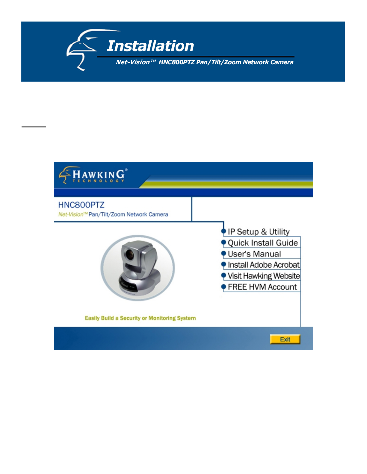
TEP 1
S : Insert the Hawking Net-Vision
u low
sho ld load automatically. (See Figure 1-1 be
e lower left corner of your screen, open “My Computer”, and double click on the CD-ROM icon.
th
yo
TM
HNC800PTZ Installation & Utilities CD into your CD-ROM Drive. The main page
.) If the CD’s Autorun page does not load automatically, cl k on “
Figure 1-1. CD Autorun main page
ic Start” in
4
Page 5
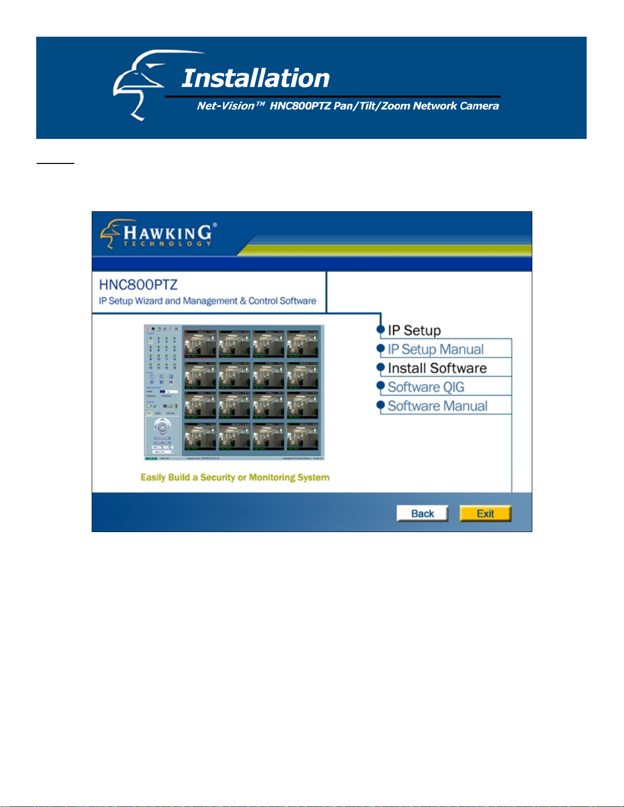
STEP 2: You will see several links on the right hand side of the CD Autorun’s main page (Figure 1-1). Click on “IP
etup & Utility” to enter the page for the IP Setup Wizard and Management & Control Software. (See Figure 1-2 below.) S
Figure 1-2. IP Setup Wizard and Management & Control Software page
5
Page 6
STEP 3: You will see several links on the right hand side of the IP Setup Wizard and Management & Control Software
page (Figure 1-2). Click on “IP Setup”. This will launch the InstallShield Wizard that installs the IP Setup Wizard
program on your PC. (See Figure 1-3 below.)
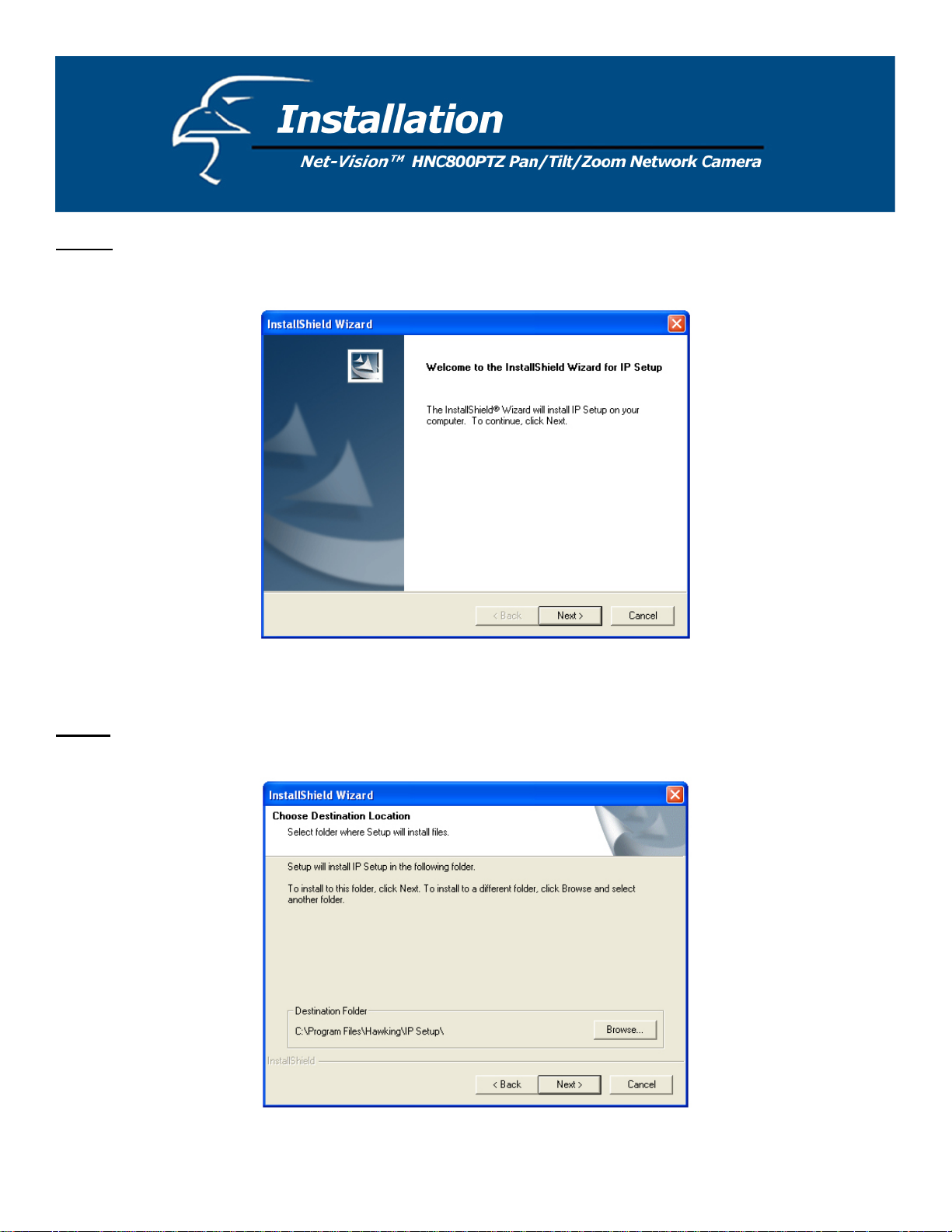
Figure 1-3. InstallShield Welcome page
TEP 4
S : Select the installation directory for the IP Setup Wizard application and click on “Next”. (See Figure 1-4 below).
ou can also select a directory other than the Default one by clicking on “Browse…”
Y
Figure 1-4. Select a directory for the IP Setup Wizard
6
Page 7

STEP 5: Select a program folder to install the IP Setup Wizard application into and then click on “Next”. (See Figure 1-5
below.)
Figure 1-5. Select a program folder
STEP 6: Click on “Finish”, to complete the installation. (See Figure 1-6 below.)
Figure 1-6. Complete the installation
7
Page 8

STEP 7: On ce the IP Setup wizard has been installed onto your PC, an IP Setup icon will app ear on your PC’s Desktop. Click on
is icon to run the IP Setup wizard.
th
Figure 1-7. IP Setup desktop icon
8
Page 9

2.1 User Interface
When you click on the IP Setup icon on your desktop to run the wizard,
n your local area network. A “simo
rial number is different from the series number/MAC address.) This code is “HVVT” and can be found on either the right or left
se
anel of the box, or on the label on the bottom of the camera.
p
ilar” camera will have the same code of four letters at the beginning of its serial number. (The
the IP Setup program will search for similar cameras
Figure 2-1. IP Setup Wizard is searching for cameras
9
Page 10

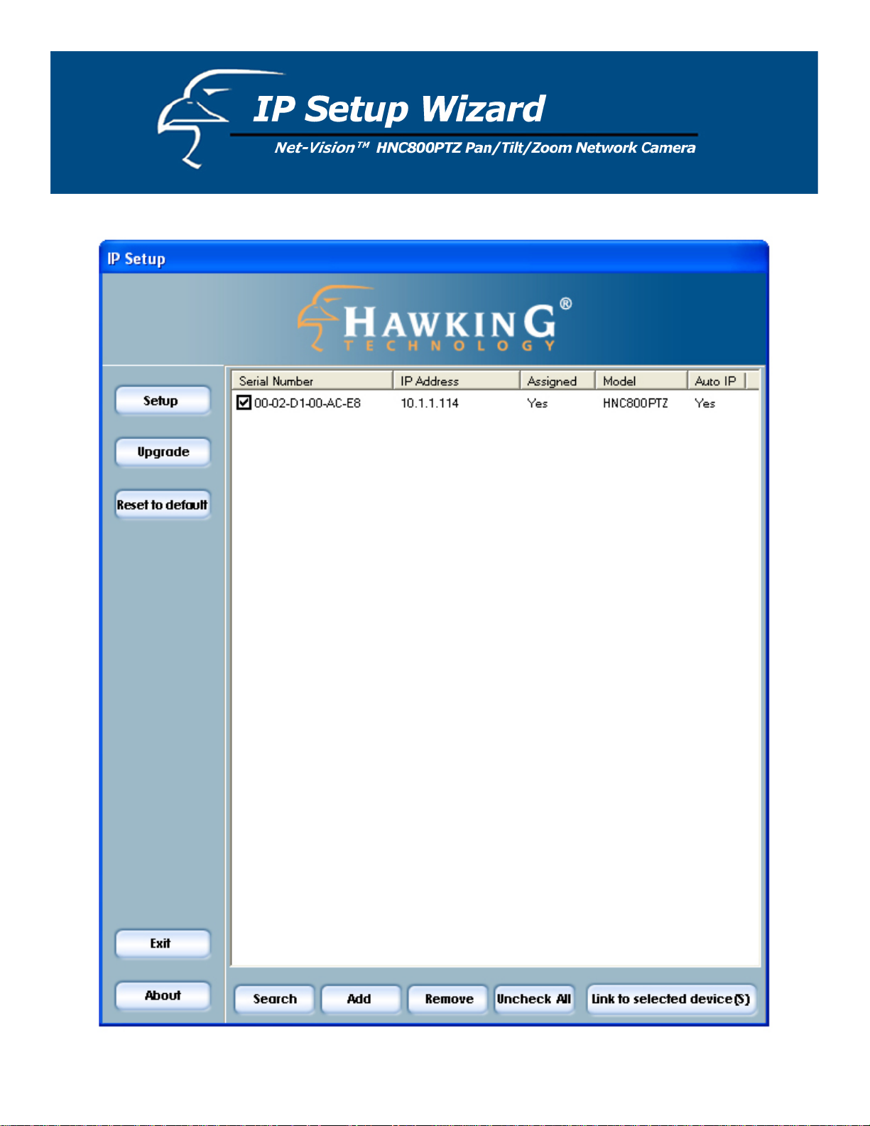
After the IP Setup Wizard has finished searching, the interface shown in Figure 2-2 will appear. You can select any device in
the list by clicking on the checkbox to the left of the device. (For a de
tailed explanation of how the IP Setup Wizard
automatically assigns a device an IP address that is consistent with your local area network [LAN] settings, please review the
Quick Installation Guide that is included in your network camera’s packaging.) The three buttons “Setup”, “Upgrade”, and
“Reset to default” will not be enabled until you have selected at least one of the devices that appears in the list.
Figure 2-2. IP Setup Wizard user interface
10
Page 11

The IP Setup Wizard allows you to set up or upgrade multiple devices (of the same model) at the same time. If you select
different models, the buttons will be disabled. (In this case, the model number is HNC800PTZ.) There are five buttons on
the bottom of the main page (see Figure 2-3 below), and five buttons on the left panel of the main page (see Figure 2-4).
Figure 2-3. Action buttons
.1.1 Action Buttons
2
Figure 2-4. Function buttons
Clicking on this button will clear the device list and cause the IP Setup Wizard to search for available
network cameras on the LAN again. This will take about 5 seconds.
To set up or update devices that are not on the same subnet to the LAN using the IP Setup Wizard,
you can click on this button to add them manually. Clicking on this button will prompt a pop-up
dialog as shown in Figure 2-5. You can input the desired IP address and click on “Ok” to add the
network camera to the device list.
Figure 2-5. “Add a device” dialog
11
Page 12

Clicking on this button will remove all the selected devices from the device list. The devices that you
remove may show up again if you click on the “Search” button or if you add them into the list
manually.
If you have selected several devices simultaneously, this button will allow you to uncheck all
the selected cameras with one click instead of one-by-one.
.1.2 Function Buttons
2
Clicking on this button will open a web browser to the web user interfaces for all of
the selected devices (one browser window per device)
.
Click on this button to modify the settings of the selected devices. For more details, please refer to
section 2.2: Setup.
Click on this button to upgrade the firmware of the selected devices. For more details,
to section 2.3: Upgrade.
Click on this button to load the factory default settings for the selec
ted devices.
Click on this button to close the IP Setup Wizard.
Click on this button to get information about the IP Setup Wizard
.
please refer
12
Page 13

2.2 Setup
When you select o e or more devices (of the same model), the “Setup” button will be enabled. Click on it to modify the
n
settings of the selected device(s). After clicking on the “Setup” button, the IP Setup Wizard will try to connect to the
elected device(s). If authentication fails, it will prompt a popup dialog (see Figure 2-6) to ask for the correct password
s
and HTTP port number. (If you have entered a port number other than the default Port 80, you will need to enter it here.)
Figure 2-6. Authentication dialog box
2.2.1 System Setting
After connecting to
following page.
one of the selected devices, the System Settings page will appear, as shown in Figure 2-7 on the
Click on this
button to go back to the previous page or main page.
Click on this
button to keep the settings and go to the next page.
Click on this button to discard the settings of the current page and go to the next page.
13
Page 14

2.2.1.1 Change Host Name
The “host name” is used for the homepage title of network camera’s main web user interface page and is displayed as the
title over the video window on the main page. The maximum string length is 40 characters or 20 characters in doublebyte-character-systems, such as Chinese or Japanese.
.2.1.2 Change root password
2
o change the administrator’ in both the “Root password” and “Confirm
T s password, type the new password identically
assword” text boxes. For security purposes, the new password will be displayed as asterisks in both boxes. The
p
aximum password length is 14 characters.
m
Figure 2-7. System Settings
14
Page 15

2.2.1.3 Adjust date and time
There are three ways to adjust the system date and time. The easiest way is to make the Network Camera "Synchronize
with computer time". The second way, “Manual”, allows you to set the date and time manually by entering new values.
otice the format in the related fields while tBe sure to n
“Automatic”, allows you to make the network camera automatically synchronize with time-servers over the Internet
every hour.
2.2.2 Network Settings
licking “Next” in ndow. In this
C the main System Settings window (Figure 2-7) will take you to the Network Settings wi
indow, you can change the network camera’s IP address, subnet mask, default gateway/router, primary DNS, and
w
econdary DNS. (See Figure 2-8 below.)
s
yping, so that you input the values correctly. The third way,
Figure 2-8. Network Settings
.2.2.1 Fix the IP address
2
hecking the "Reset IP address at next boot" box will force the network camera to reconfigure its IP address whenever
C
reboots. The preferred method, though, is to use a fixed IP address. If you want the camera to use a fixed IP address,
it
lease uncheck the "Reset IP address at next boot" and assign the camera an available IP address that is consistent with
p
our existing network settings. If you selected more than one device, you will not be able to change the IP address and
y
e IP address field will be disabled.
th
.2.2.2 Basic Network Settings
2
ou can setup the network setting by this page. Usually this is no need to be changed, if you do change it please make
Y
sure you input the correct setting or the device
may not be reachable.
15
Page 16

2.2.3 Apply to selected device(s)
After configuring all the settings and clicking the “Next” button, the “Apply” window will appear. Click on “Apply” to
apply/confirm the changes to the selected device(s) or click on the “Previous” button to go back to the previous window
and modify the settings.
Figure 2-9. “Apply” page
16
Page 17

2.3 Upgrade
When you select one device or multiple devices (of the same model), the “Upgrade” button will be enabled. Click on it to
pgrade the firmware of the selected device(s). After clicking on the “Upgrade” button, the IP Setup Wizard will try to
u
onnect to the s to ask for the correct password
c elected device(s). If the authentication fails, it will prompt a pop-up dialog
nd HTTP port number. (See Figure 2-10 below.)
a
Figure 2-10. Authentication
.3.1 Device Information
2
fter connecting to the selected device(s), the display will appear as shown in Figure 2-13 on the following page. If you
A
elect more than one device, the “Device Info” tab will show all the selected devices. (See Figure 2-11 below.) You can
s
witch to a specific camera’s info (see Figure 2-12) by pressing the Tab key or double clicking on the device list.
s
Figure 2-11. Device Info
17
Page 18

Figure 2-12. Camera Info
Fi w
gure 2-13. Upgrade windo
18
Page 19

2.3.2 Package Information
he package inform hat you
T ation section will display the following important information about the firmware file t
elected:
s
Firmware version: The version number of the selected firmware.
•
Supported script version: The maximum script version that the firmware can support.
•
Web page version: The version number of the web page.
•
Script version: Script version used by the web page and server script.
•
Viewer plug-in version: The version number of the viewer plug-in.
•
Upgrade plug-in version: The version number of the upgrade plug-in
•
Supported language: The language that the selected file supports.
•
Figure 2-14. Firmware Package/File Info
.3.3 File Selection
2
ou can use the file combo list below the Package Information to browse and locate the file that you want to upgrade onto
Y
e selected device(s). After selecting the file, the IP Setup Wizard will check whether or not the file you selected is
th
rrect. If it is correct, then the Package Information section will display the information about the file and enable the
co
Upgrade” button. You can then click on the button to upgrade the firmware. If it is not correct, it will prompt a
“
arning message to appear.
w
19
Page 20

2.3.4 Upgrade
Click on t
rogress of the upgrade process. (See Figure 2-15 below.) After the update process has completed, please click “Done” to
p
nish.
fi
he “Upgrade” button to upgrade the firmware for the selected device(s). A dialog will pop up to display the
Figure 2-15. Update Progress
20
 Loading...