

Page 1
1
Page 2

Trademarks & Copyright
Windows 95/98/ME and Windows NT/2000/XP are registered trademarks of Microsoft Corp. All other brands and product names are
trademarks of their respective companies.
No part of this publication may be reproduced in any form or by any means or used to make any derivative (such as translation,
transformation or adaptation) without the express written consent of the manufacturer as stipulated by the United States Copyright Act
of 1976.
FCC Certifications
This equipment has been tested and found to comply with the limits for a Class B digital device, pursuant to Part 15 of the FCC Rules.
These limits are designed to provide reasonable protection against harmful interference in a residential installation. This equipment
generates, uses and can radiate radio frequency energy and, if not installed and used in accordance with the instructions, may cause
harmful interference to radio communications. However, there is no guarantee that interference will not occur in a particular
installation. If this equipment does cause harmful interference to radio or television reception, which can be determined by turning the
equipment off and on, the user is encouraged to try to correct the interference by one or more of the following measures:
x Reorient or relocate the receiving antenna.
x Increase the separation between the equipment and receiver.
x Connect the equipment into an outlet on a circuit different from that to which the receiver is connected.
x Consult the dealer or an experienced radio/TV technician for help.
Shielded interface cables must be used in order to comply with emission limits.
You are cautioned that changes or modifications not expressly approved by the party responsible for compliance could void your
authority to operate the equipment.
This device complies with Part 15 of the FCC rules. Operation is subject to the following two conditions: (1) This device may not
cause harmful interference, and (2) This device must accept any interference received, including interference that may cause undesired
operation.
CE Mark Warning
This is a Class B product. In a domestic environment, this product may cause radio interference, in which case the user may be
required to take adequate measures.
All trademarks and brand names are the property of their respective proprietors.
Specifications are subject to change without prior notification.
2
Page 3

HAWKING LIMITED WARRANTY
Hawking Technology guarantees that every HNC300 Network Camera and every HNC320G Wireless-G Network
Camera is free from physical defects in material and workmanship under normal use for (1) year from the date of
purchase. If the product proves defective during this one-year warranty period, call Hawking Customer Service in
order to obtain a Return Authorization number. Warranty is for repair or replacement only. Hawking
Technology does not issue any refunds. BE SURE TO HAVE YOUR PROOF OF PURCHASE. RETURN
REQUESTS CANNOT BE PROCESSED WITHOUT PROOF OF PURCHASE. When returning a product, mark
the Return Authorization number clearly on the outside of the package and include your original proof of
purchase.
IN NO EVENT SHALL HAWKING TECHNOLOGY’S LIABILTY EXCEED THE PRICE PAID FOR THE PRODUCT
FROM DIRECT, INDIRECT, SPECIAL, INCIDENTAL OR CONSEQUENTIAL DAMAGES RESULTING FROM THE
USE OF THE PRODUCT, ITS ACCOMPANYING SOFTWARE OR ITS DOCUMENTATION. Hawking Technology makes
no warranty or representation, expressed, implied or statutory, with respect to its products or the contents or use of this
documentation and all accompanying software, and specifically disclaims its quality, performance, merchantability, or fitness
for any particular purpose. Hawking Technology reserves the right to revise or update its products, software, or
documentation without obligation to notify any individual or entity. Please direct all inquiries to:
techsupport@hawkingtech.com
.
3
Page 4

About This User’s Manual 6
Introduction 7
System Requirements 8
Features and Benefits 9
Physical Description 10
HNC300
Front Panel 10
Power LED 10
Link LED 10
Rear Panel 11
Network Cable Connector 11
DC Power Connector 11
Reset Button 11
Top Panel 12
Screw Hole 12
Bottom Panel 12
Screw Hole 12
HNC320G
Front Panel 13
Power LED 13
Link LED 13
Rear Panel 14
Network Cable Connector 14
DC Power Connector 14
Reset Button 14
Antenna Connector 14
Top Panel 15
Screw Hole 15
Bottom Panel 15
Screw Hole 15
Unpacking the Camera 16
Hardware Installation 17
HNC300
Connect an Ethernet Cable 17
Attach the External Power Supply 17
HNC320G
Attach Wireless Antenna 18
Connect an Ethernet Cable 18
Attach the External Power Adapter 19
Security 20
Web Configuration 21
Web Configuration 21
Main Menu Page 21
4
Page 5

System Administration 22
HNC300 22
HNC320G 22
HNC300
System Administration: Management 22
System Administration: Configuration 25
System Administration: Tools 35
System Administration: Help 38
HNC320G
System Administration: Management 39
System Administration: Configuration 42
System Administration: Tools 55
System Administration: Help 58
View Image – ActiveX Mode 59
View Image – Java Mode 60
Camera Applications
Applications 61
Home Applications 61
SOHO (Small Office, Home Office) Applications 62
IPView SE Application Installation 63
IPView SE – Getting Started 68
IPView SE Control Panel 68
How to Add Camera 69
How to Change Cameras 72
How to Connect/Disconnect the Image 73
How to Delete a Camera 74
Extra Information 75
How to Adjust the Property Setting 75
Motion Setting 77
Update Firmware 78
How to Adjust the Recording Settings 79
Appendix
A. Frequently Asked Questions 80
B.Ping Your IP Address 81
C. Troubleshooting 81
D. Upgrade Firmware 83
E.Time Zone Table 84
F. Xplug Control Installation 85
G. Adjusting the Camera Focus 88
H.Specifications: HNC300 89
HNC320G 91
I. How to View Your Camera via the Internet 93
J. Glossary of Terms 98
5
Page 6

This user’s manual gives a full explanation of the HNC300 (Wired) Network Camera and HNC320G Wireless-G Network
Camera, including a description of features, installation procedures, web configuration, and other functions. Also
included in the user’s manual are the operating procedures for the IPView SE application.
6
Page 7

Thank you for purchasing either the HNC300 Network Camera or the HNC320G Wireless-G Network Camera. The
HNC300 connects directly to an Ethernet or Fast Ethernet network. The HNC320G can also connect directly to an
Ethernet or Fast Ethernet network, but also supports the IEEE 802.11b/g wireless standard. The HNC300 Series (the
collective title for the HNC300 & HNC320G models) network cameras are different from conventional PC cameras in
that they are standalone systems with built-in CPUs and web servers. Therefore, they connect directly to the local area
network (LAN) and do not need to be connected to a designated PC. Thus, they provide a low cost solution that can
transmit high quality video images for monitoring and surveillance. The network cameras can be managed remotely, and
can be accessed and controlled from any PC/Notebook over the LAN or Internet using only a web browser. The simple
installation procedures and web-based interface offer easy integration to your network application environments.
7
Page 8
HNC300 & HNC320G
Network:
Local Area Network (HNC300 & HNC320G): 10Base-T Ethernet or 100Base TX Fast Ethernet
Wireless Local Area Network (HNC320G): IEEE 802.11b/g Wireless LAN
\
Recommended PC or Notebook to Access the HNC300 & HNC320G:
For Web Browser Users
x Operating System: Microsoft Windows 98SE/ME/2000/XP
x CPU: Pentium II, 266 MHz or above
x Memory Size: 32 MB (64 MB recommended)
x VGA card resolution: 800x600 or above
x Internet Explorer 5.0 or above (ActiveX & JAVA Mode – Image View for Windows OS and JAVA Mode –
Image View for other OS)
x Netscape 6.0 or above (JAVA Mode – Image View)
IPView SE Application:
x Supported Operating Systems: Win 98 SE, Win 2000, Win Me, Win XP
x System requirements for IPView SE:
CPU: Pentium III, 450 MHz or above
Memory Size: 128 MB (256 MB recommended)
VGA card resolution: 800x600 or above
8
Page 9

This section describes the features and benefits of the HNC300 Network Camera & HNC320G Wireless-G Network
Camera.
Simple to Use
The HNC300 and HNC320G are standalone systems with built-in CPUs, and thus, require no special hardware or
software such as PC frame grabber cards. The HNC300 and HNC320G support both ActiveX mode for Internet Explorer
and Java mode for Internet Explorer and Netscape Navigator. Therefore, all that is required is web browser software such
as Internet Explorer 5.0 or above, or Netscape 6.0 or above. All you need is a valid IP address to view the picture from
your network camera.
Supports a Variety of Platforms
The HNC300 & HNC320G both support TCP/IP networking, SMTP e-mail, HTTP and other Internet related protocols.
Both models can be utilized in mixed operating system environments such as Windows, Unix, and Mac. They can easily
be integrated into other Internet/Intranet applications.
Web Configuration
Using a standard web browser, the administrator can configure and manage the HNC300 or HNC320G directly from its
own web page via the web.
HNC300
The administrator can set up to 8 usernames and passwords via the privilege settings.
HNC320G
The administrator can set up to 64 usernames and passwords via the privilege settings.
Remote Utility
The powerful IPView SE application assigns the administrator a pre-defined user ID and password through which, he/she
can modify the HNC300/HNC320G settings from a remote site via the Intranet or Internet. For added convenience, when
new firmware becomes available, the administrator can also upgrade remotely over the network. Users are also allowed
to monitor the images and take snapshots.
Broad Range of Applications
Using today’s high-speed Internet services, the HNC300 and HNC320G network cameras can provide an ideal high
performance, cost-effective solution that delivers live video images over the Intranet and Internet for remote monitoring
and surveillance. The network cameras allow remote access from a web browser for live image viewing. They also allow
administrators to manage and control the network cameras anytime from anywhere in the world. You can set up the
network cameras to monitor various objects and locations such as homes, offices, banks, hospitals, child-care centers,
amusement parks and a variety of other industrial and public areas. The network cameras can also be used for intruder
detection, still image capture for archiving, and many other applications.
9
Page 10
HNC300
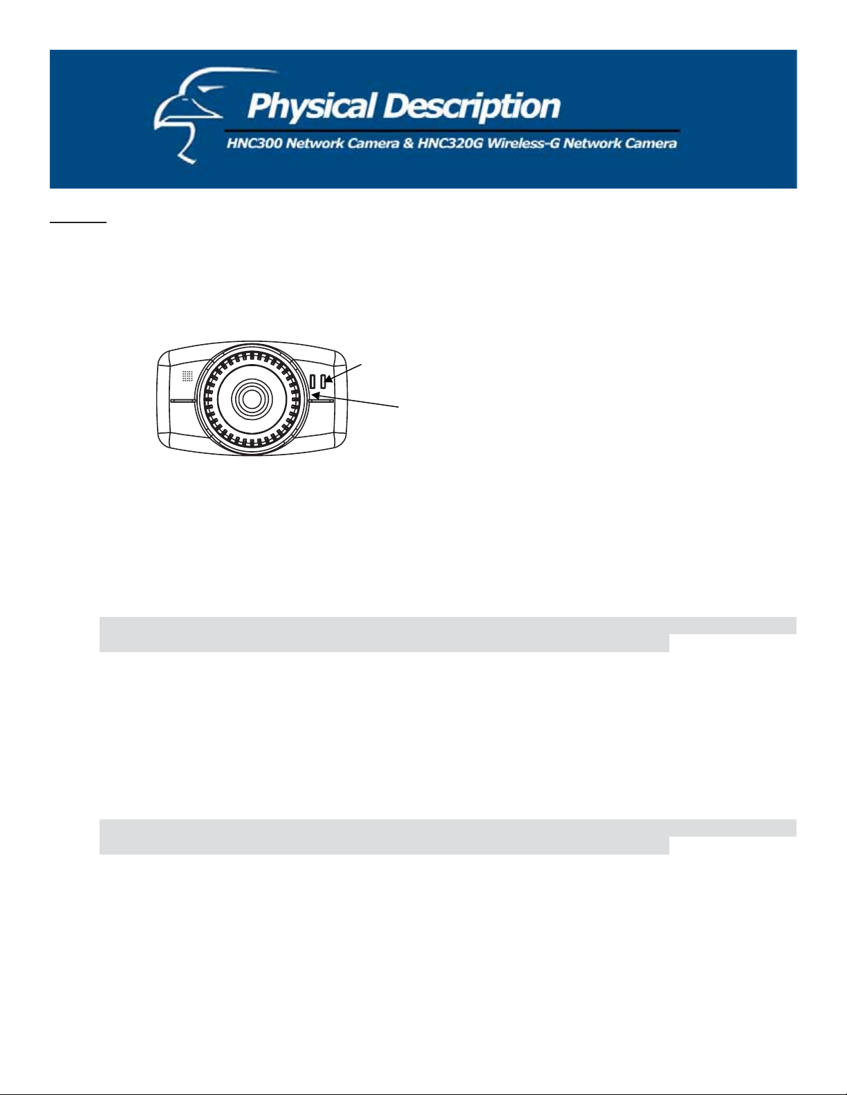
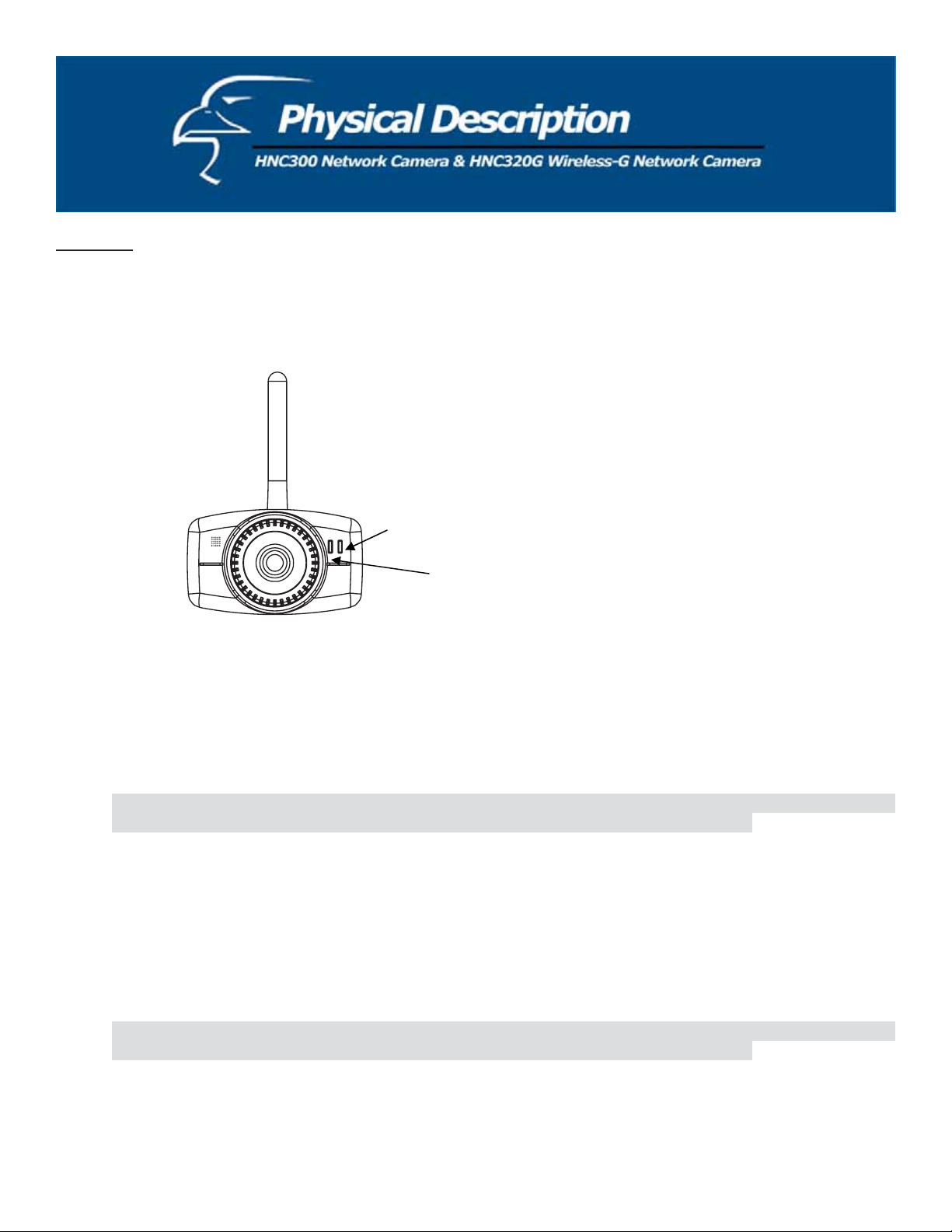
This section describes the externally visible features of the HNC300.
Front Panel
Link LED
Power LED
Power LED
The “Power” LED is located to the right of the camera’s lens (when facing the camera). A steady blue light confirms that
the camera is powered on.
Note:
The “Power” LED has three settings with which to control the light illumination while monitoring: Normal / Off /
Dummy. Please refer to the “Web Configuration” section for detailed information and usage.
Link LED
The “Link” LED is located on the far right side of the network camera’s lens (when facing the network camera). It is
located to the right of the “Power” LED. A steady orange light confirms a good connection. Depending on the data
traffic, the LED will begin to flash to indicate that the camera is receiving/transmitting from/to the network.
Note:
The “Link” LED has three settings with which to control the light illumination while monitoring: Normal / Off /
Dummy. Please refer to the “Web Configuration” section for detailed information and usage.
10
Page 11

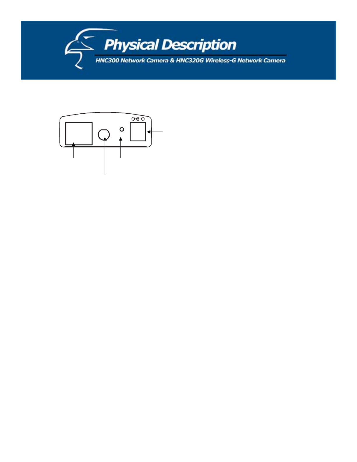
Rear Panel
10/100 Ethernet
Reset
DC Power
Connector
DC 5V
Ethernet Cable
Reset Button
Port
Network Cable Connector
The rear panel of the network camera features an RJ-45 connector for 10Base-T Ethernet or 100Base-TX Fast Ethernet
connections (using Category 5 twisted-pair cabling). The port supports the N-Way protocol and the “Auto-MDIX”
function, thereby allowing the network camera to automatically detect or negotiate the transmission speed of the network.
DC Power Connector
The DC power input connector is located on the rear panel of the network camera and is labeled DC 5V with a single jack
socket to supply power to the camera. Power will be generated when the power supply is connected to a wall outlet.
Reset Button
Reset will be initiated when the reset button is pressed once and the “Power” LED begins to flash.
Factory Reset will be initiated when the reset button is pressed continuously for at least three seconds or when the “Power
LED” begins to light up. Release the reset button and the “Power” LED will begin to flash, indicating that the network
camera is utilizing the factory reset. When factory reset is completed, the IP address will return to the default setting of
192.168.0.20.
11
Page 12
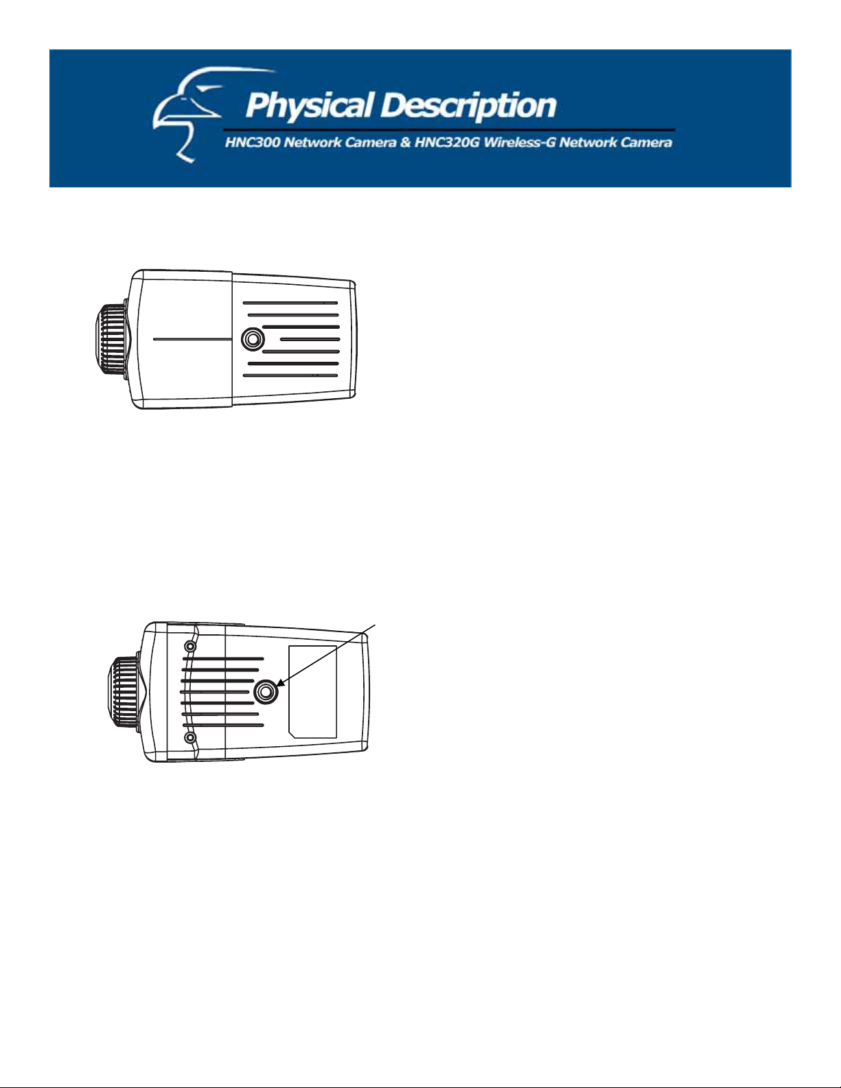
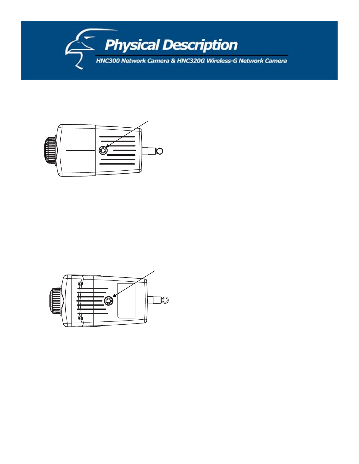
Top Panel
Screw Hole
Located on the top panel of the network camera, the screw hole is used to connect the camera stand onto the camera by
attaching the screw head on the camera stand into the screw hole of the camera.
Bottom Panel
Screw Hole
Screw Hole
Located on the bottom panel of the network camera, the screw hole is used to connect the camera stand onto the camera
by attaching the screw head on the camera stand into the screw hole of the camera.
12
Page 13
HNC320G
This section describes the externally visible features of the HNC320G.
Front Panel
Link LED
Power LED
Power LED
The “Power” LED is located to the right of the camera’s lens (when facing the camera). A steady blue light confirms that
the camera is powered on.
Note:
The “Power” LED has three settings with which to control the light illumination while monitoring: Normal / Off /
Dummy. Please refer to the “Web Configuration” section for detailed information and usage.
Link LED
The “Link” LED is located on the far right side of the network camera’s lens (when facing the wireless network camera).
It is located to the right of the “Power” LED. A steady orange light confirms a good connection. Depending on the data
traffic, the LED will begin to flash to indicate that the camera is receiving/transmitting from/to the network.
Note:
The “Link” LED has three settings with which to control the light illumination while monitoring: Normal / Off /
Dummy. Please refer to the “Web Configuration” section for detailed information and usage.
13
Page 14
Rear Panel
10/100 Ethernet
ANT
Reset
DC Power
Connector
DC 5V
Network Cable
Reset Button
Connector
Antenna
Connector
Network Cable Connector
The rear panel of the wireless network camera features an RJ-45 connector for 10Base-T Ethernet or 100Base-TX Fast
Ethernet connections (using Category 5 twisted-pair cabling). The port supports the N-Way protocol and the “AutoMDIX” function, thereby allowing the wireless network camera to automatically detect or negotiate the transmission
speed of the network.
DC Power Connector
The DC power input connector is located on the rear panel of the wireless network camera and is labeled DC 5V with a
single jack socket to supply power to the camera. Power will be generated when the power supply is connected to a wall
outlet.
Reset Button
Reset will be initiated when the reset button is pressed once and the “Power” LED begins to flash.
Factory Reset will be initiated when the reset button is pressed continuously for at least three seconds or when the
“Power” LED begins to light up. Release the reset button and the “Power” LED will begin to flash, indicating that the
wireless network camera is utilizing the factory reset. When factory reset is completed the wireless camera will be set to
Channel 11 by default and the ESS-ID is set as “NULL String”. (This default setting will let the wireless camera
connect to ANY access point on the infrastructure network). The IP address will also return to the default setting of
192.168.0.20.
Antenna Connector
The SMA-type antenna connector is located on the rear panel of the wireless camera, thereby providing connection for a
high-sensitivity antenna that is included with the device. The antenna can rotate, thus allowing the user to adjust its
position to obtain the best signal.
14
Page 15
Top Panel
Screw Hole
Screw Hole
Located on the top panel of the wireless camera, the screw hole is used to connect the camera stand onto the camera by
attaching the screw head on the camera stand into the screw hole of the wireless camera.
Bottom Panel
Screw Hole
Screw Hole
Located on the bottom panel of the wireless camera, the screw hole is used to connect the camera stand onto the camera
by attaching the screw head on the camera stand into the screw hole of the wireless camera.
15
Page 16

Unpack and Inspect
Open the package and carefully remove all items.
The complete HNC300 package consists of:
x One HNC300 (Wired) Network Camera
x One Installation CD-ROM
x One Quick Installation Guide
x One DC power adapter
x One Camera Stand
x One RJ-45 Ethernet Cable
x One Hosted Video Management Datasheet
The complete HNC320G package consists of:
x One HNC320G Wireless Network Camera
x One External Wireless Antenna
x One Installation CD-ROM
x One Quick Installation Guide
x One DC power adapter
x One Camera Stand
x One RJ-45 Ethernet Cable
x One Hosted Video Management Datasheet
Please check to make sure that the unit was not damaged during shipping and that no items are missing. If you encounter a
problem, please contact your dealer.
Please read this manual thoroughly, and follow the installation and operation procedures contained within.
Connecting the HNC300/HNC320G to the Camera Stand
The HNC300 and HNC320G packages include a camera stand (installation is optional) with a swivel ball screw head that
can be attached to the camera’s screw holes. Attach the camera stand to the camera and orient it in the most appropriate
position for your specific application. In addition, there are three holes located on the base of the camera stand, thereby
allowing the camera to be securely mounted on the ceiling or wall.
16
Page 17
This section describes the hardware installation procedures for the HNC300 and HNC320G.
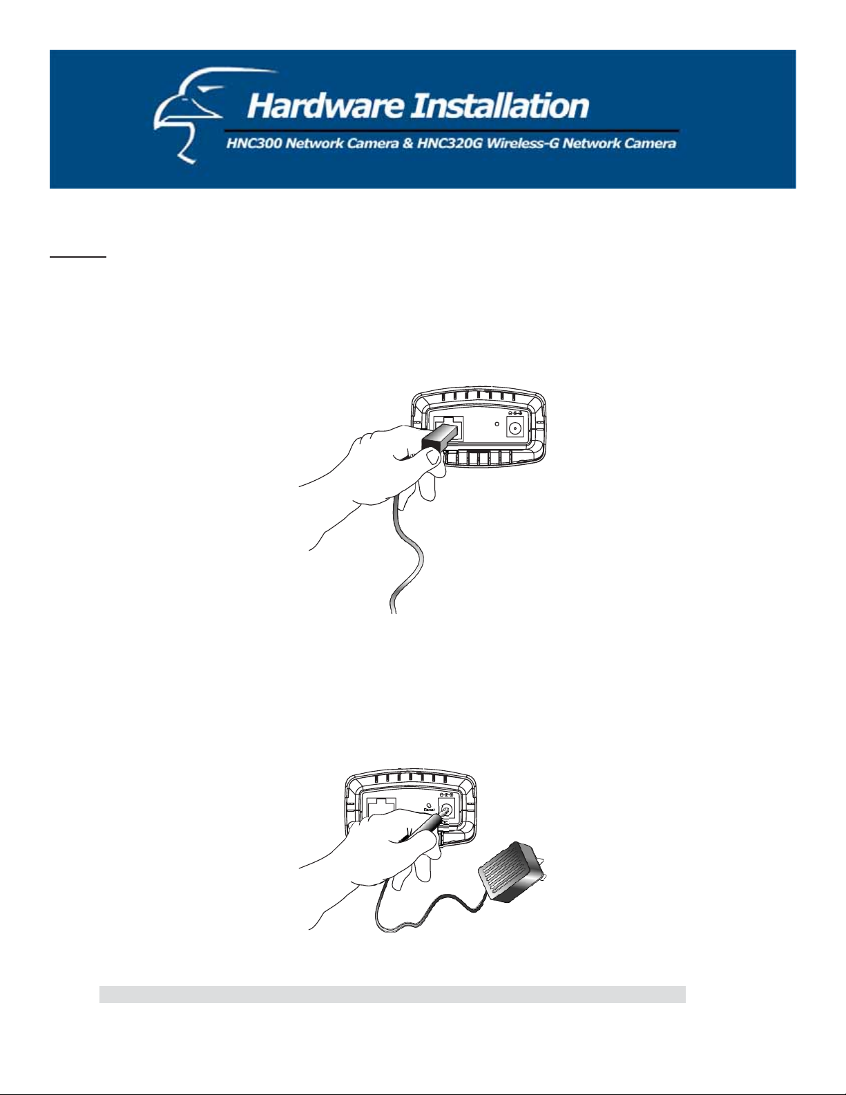
HNC300
Connect an Ethernet Cable
Connect an Ethernet cable to the Ethernet cable port located on the rear panel of the camera, and attach the other end to
the network.
10/100 Ether net
Reset
DC5V
Attach the External Power Supply
Attach the external power supply to the DC power input connector located on the rear panel of the camera. The input
connector is labeled “DC 5V”. Connect it to your local power supply.
10/100 Eth ernet
Reset
DC5V
Note:
Confirm that the device is receiving power by making sure that the “Power” LED is illuminated.
17
Page 18
HNC320G
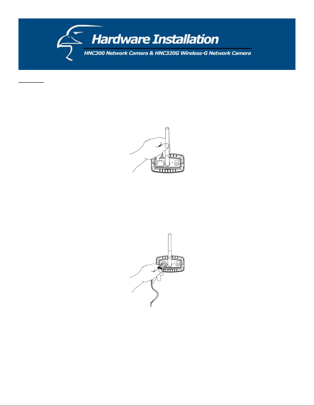
Attach Wireless Antenna
On the rear panel of the wireless camera, screw into the antenna connector the single external antenna that was included in
the product packaging.
Connect an Ethernet Cable
Connect an Ethernet cable to the Ethernet cable port located on the rear panel of the camera, and attach the other end to
the network.
18
Page 19
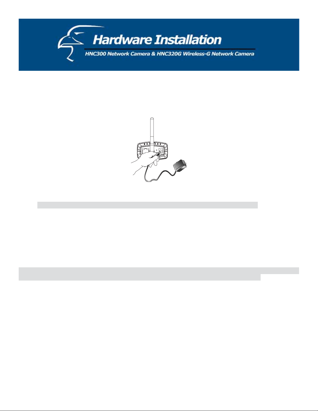
Attach the External Power Supply
Attach the external power supply to the DC power input connector located on the rear panel of the camera. The input
connector is labeled “DC 5V”. Connect it to your local power supply.
Note:
Confirm that the device is receiving power by making sure that the “Power” LED is illuminated.
Please Note: Once you have configured your HNC320G camera so that it is connected to your existing wireless network
(i.e. you have configured it with all the correct wireless settings), you can then remove the Ethernet cable.
19
Page 20

To ensure the highest security and prevent unauthorized usage of the HNC300 or HNC320G, the network administrator
has an exclusive privilege to access the cameras’ System Administration to change settings and control requirements that
allow entry and authorized privileges for all users. The HNC300 and HNC320G support multi-level password protection.
Access to the cameras is restricted to defined users only, who have a "User Name" and "User Password" that has been
assigned by the administrator.
Administrators can release a public user name and password so that when remote users access the HNC300 or HNC320G,
they will have access to view the images transmitted by the cameras.
Note:
When the HNC300 or HNC320G is used for the first time, it is highly recommended that the administrator set the
"Admin ID" and "Admin Password" to restrict users’ access to the cameras since the Default settings are the Null
String (i.e., the default Admin ID and Admin Password are blank). Once the ID and Password are defined, only
the administrator has access to manage the cameras. This operation should be performed as soon as possible since
the security features of the HNC300 and HNC320G will not be enabled until the "Admin ID" and "Admin
Password" are defined.
20
Page 21
This section describes the web configuration procedures for the HNC300 and HNC320G.
Web Configuration
The HNC300 and HNC320G must be configured via their built-in Web-based Configuration. Knowledge of local area
networks (LANs) will be useful when setting up the cameras.
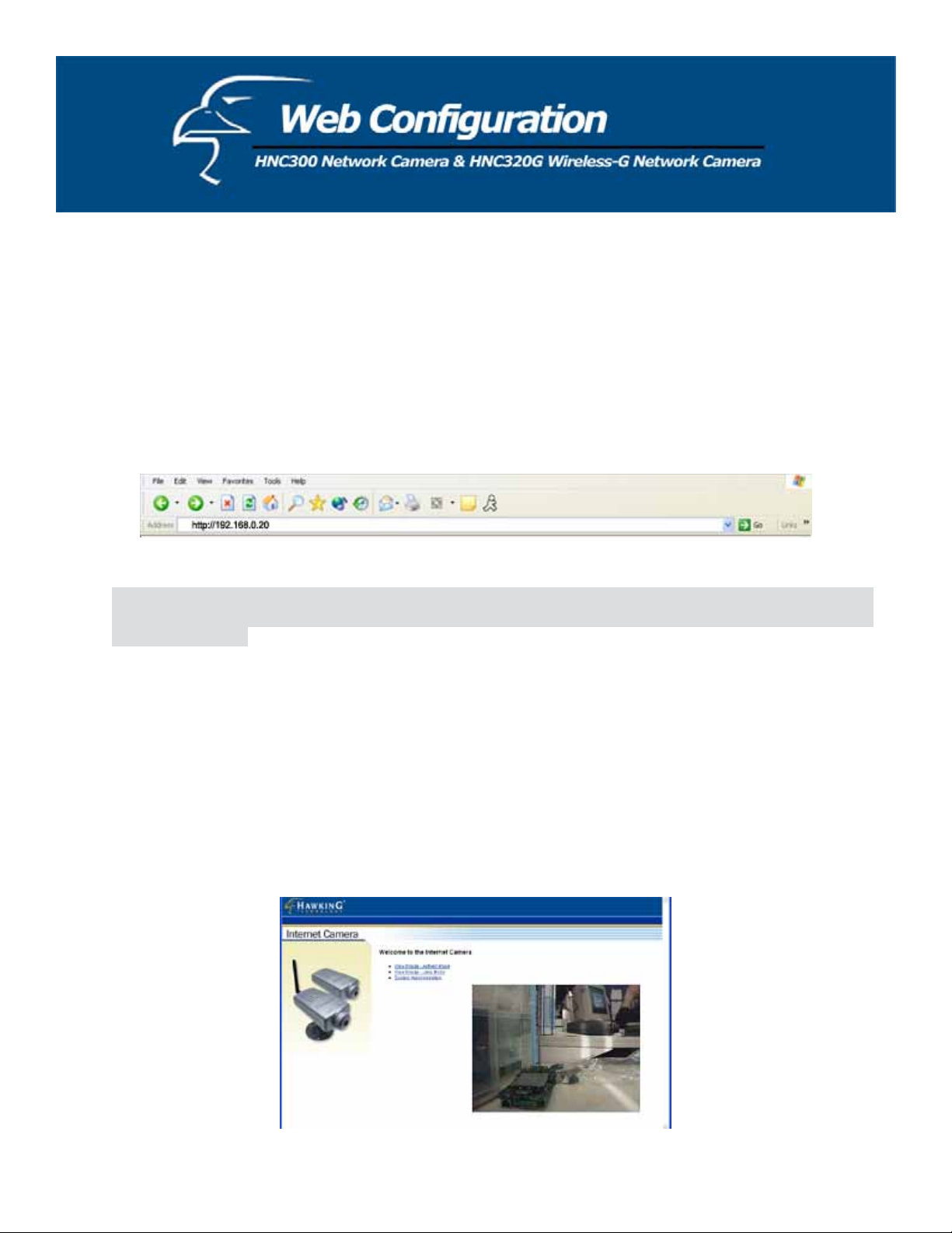
In the web browser, enter the default IP address to access the Welcome screen of the network camera. From here you can
configure your network camera. For the default IP address, type “http://192.168.0.20” in the address box. (If you have
already used the Setup Wizard to change the camera’s IP address, then enter the new IP address in the web address bar.)
The numbered portion of the address is the IP address of your camera.
Note:
The first three segments of the PC’s IP address must correspond with the first three segments of the camera’s
IP address in order for them to communicate. The PC and network camera must have the same “Subnet” and
“Default Gateway”.
Main Menu Page
Once the IP address is entered in the web address bar, the screen shown below will appear with a still image. There will
be three options to choose from to set up and view your network camera. They are as follows:
x View Image – ActiveX Mode
x View Image – Java Mode
x System Administration
21
Page 22
System Administration
Click on “System Administration” on the “Welcome” screen to access the settings for the network camera. There will be
several options to choose from in the menu bar. They are listed below for both, the HNC300 and HNC320G.
HNC300
1. Management
2. Configuration
3. Tools
4. Help
5. Home
HNC320G
x Management
x Configuration
x Tools
x Help
x Home
HNC300
System Administration: Management
The Management window contains the information you will need to configure your camera. Click the items in the menu
bar to the right of the text “Internet Camera” to view your settings, including: System, Video, Network, and User.
22
Page 23
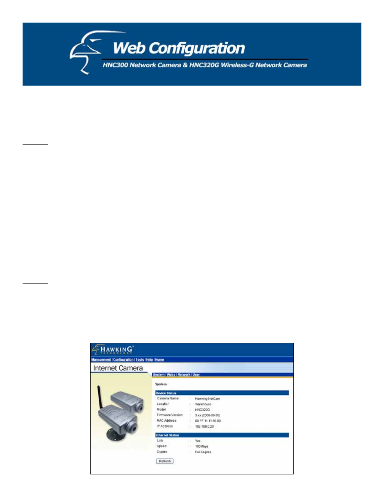
System
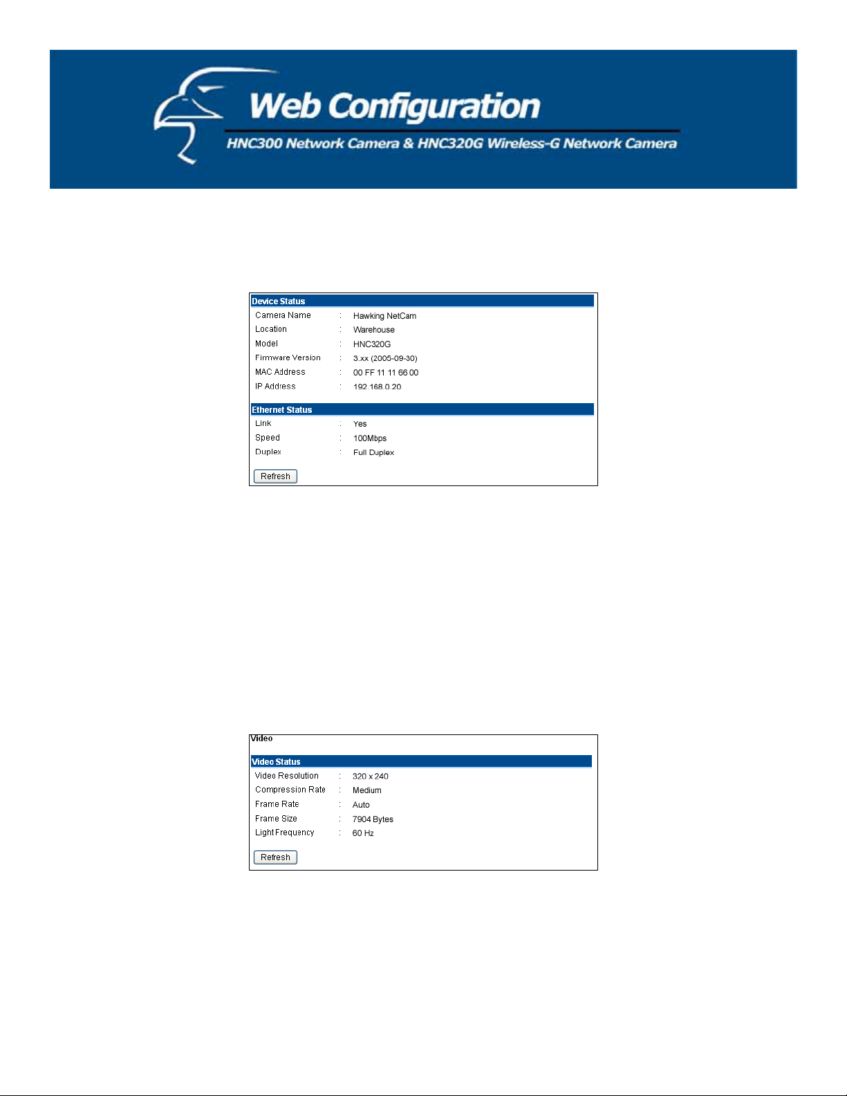
Click System to the right of the text “Internet Camera” to display the device status of your camera.
x Device Status: The camera’s vital information, including the Camera Name, Location, Model, Firmware
Version, MAC Address and IP Address, can be found in this field.
x Ethernet Status: You can monitor the camera’s network status in this field, including Link (network
connection), Speed, and the Duplex mode.
Video
Click Video to the right of the text “Internet Camera” to display your camera’s video configuration information.
x Video Status: The camera’s video configuration information, including the Video Resolution, Compression
Rate, Frame Rate, Frame Size and IP Address, can be found in this field.
23
Page 24
Network
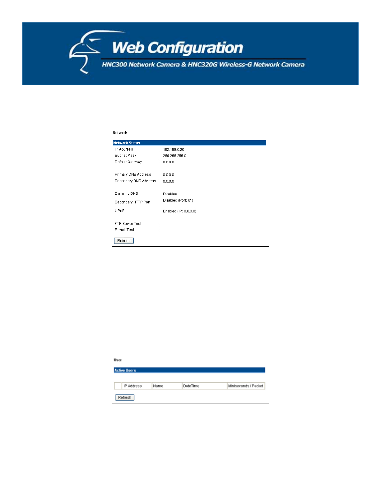
Click Network to the right of the text “Internet Camera” to display the camera’s network status information.
x Network Status: The items in this field display the camera’s network status information, such as the IP
Address, Subnet Mask, Default Gateway, Primary DNS Address, Secondary DNS Address, Dynamic DNS,
Secondary HTTP Port, and UPnP.
User
Click User to the right of the text “Internet Camera” to display the user(s) information.
x Active Users: The items in this field display the user information, including the user IP address, Name,
and Date & Time.
24
Page 25
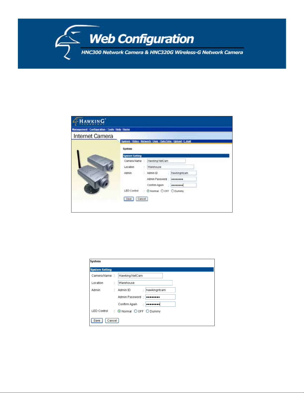
System Administration: Configuration
The Configuration window contains commands for settings that are required for inputting key details to set up the
camera for operation. Click Configuration in the top menu bar and the Configuration window will appear as below:
System
Click on System to the right of the text “Internet Camera” to adjust your camera’s basic configuration settings.
System Setting: In this field, you can configure your camera’s basic settings.
25
Page 26
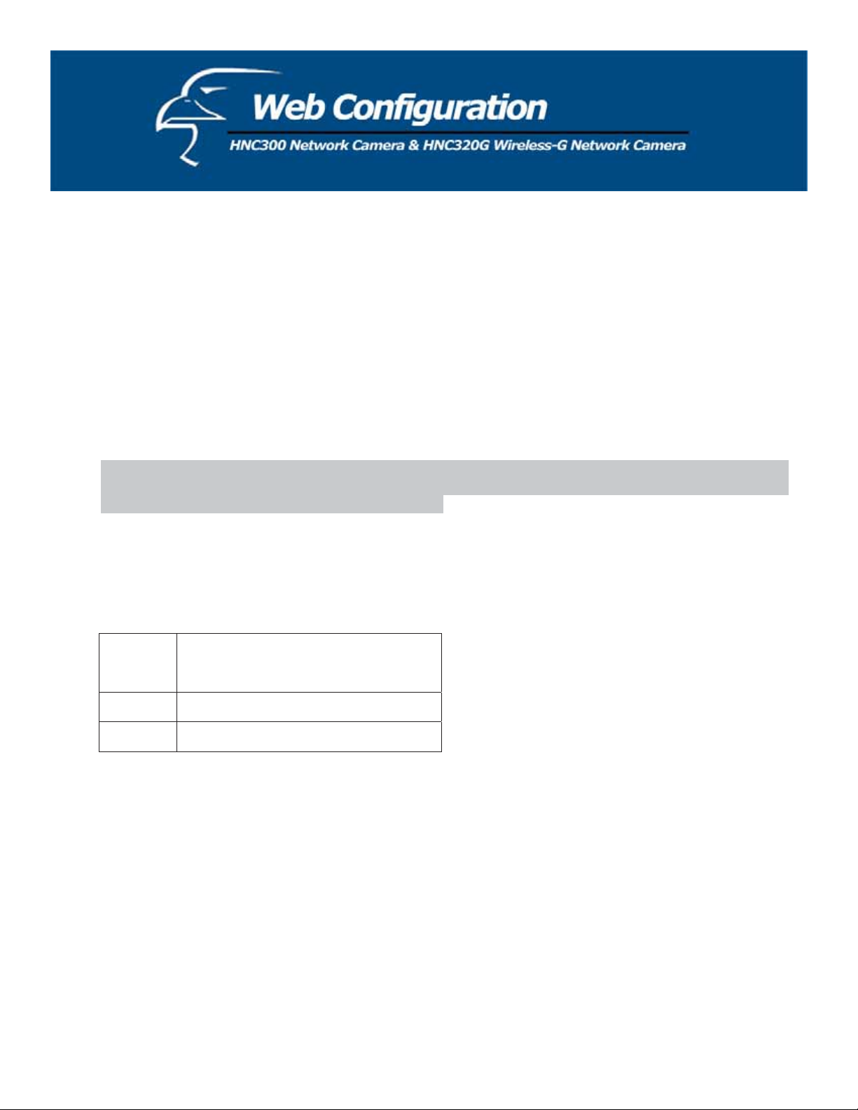
x Camera Name: This field is used to enter a descriptive name for the device. The default setting for the
Camera Name is CS-xxxxxx, where “xxxxxx” constitutes the last six digits of the device’s MAC Address. The
maximum length is 32 characters (printable ASCII).
x Location: This field is used to enter a descriptive name for the camera’s location.
x Admin: The fields in this section are used to enter the administrator’s name (“Admin ID”) and password. The
administrator’s ID and password will allow the user to access and configure the System Administration settings.
Be sure to enter the password twice to confirm the details, once in the Admin Password field and again in the
Confirm Password field.
The default settings for both the administrator user name and password are blank (or null string). The
administrator name (“Admin ID”) has a maximum length of 12 (printable ASCII) characters and the
administrator password has a maximum length of 8 (printable ASCII) characters.
It is highly recommended that you set the Admin ID and Admin Password as soon as possible to enable
security options for the camera.
NOTE: If you would like to create a user account that only has access to the video image, but not the system
administration settings, you can do this in the “User” page of the Configuration section. Instructions on how to
create such a user are provided in the pages that follow.
x LED Control: This option allows users to set up the LEDs, as desired. This feature provides flexibility when
surveillance activity is ON.
There are three options, and they are as follows:
Power - Steady On
Normal
OFF
Dummy
Link - Steady On
Note: When there is LAN activity, the LED
indicator will flash steadily.
Power - LED indicator is off.
Link – LED indicator is off.
Power - Steady On
Link - Steady On, with random flashing.
The default setting for the LED control is Normal. When you have configured the LED controls, the correct
illumination will set after 1 minute.
26
Page 27
Video
Click Video to the right of the text “Internet Camera” to configure the camera’s video settings.
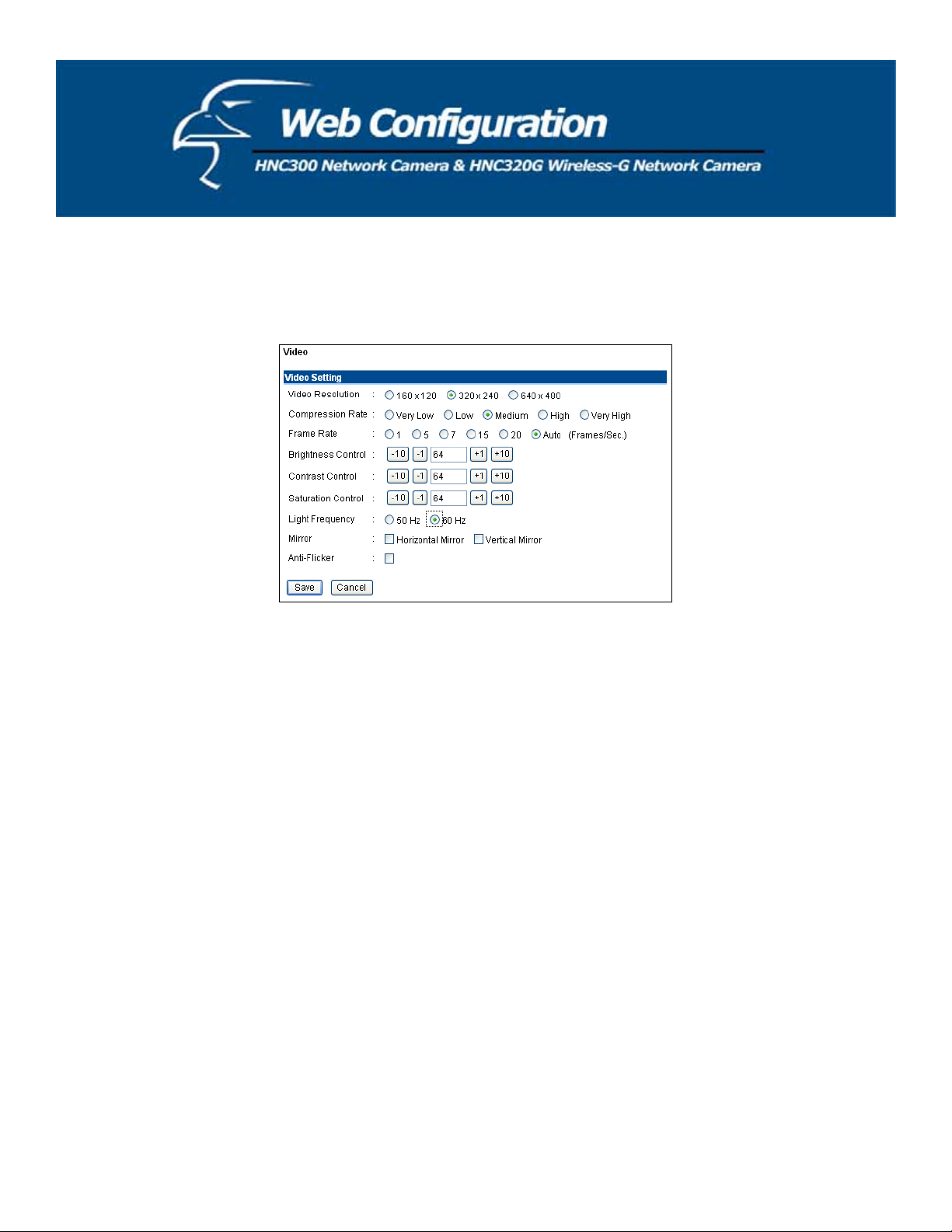
Video Setting: In this field, you can configure the camera’s basic video settings.
x Video Resolution: Select the desired video resolution format:
x Compression Rate:
Select the desired compression rate. You will have five levels to choose from,
160 x 120, 320 x 240 (default), or 640 x 480.
ranging from Very Low to Very High. A higher video compression rate will generate a more
compact file size with poorer video quality, and vise-versa. The default setting is Medium.
x Frame Rate: Select the desired frame rate. The default setting is Auto for an optimal frame rate.
x Brightness Control: Adjust the brightness level; the default setting is 64.
x Contrast Control: Adjust the contrast level; the default setting is 64.
x Saturation Control: Adjust the saturation level; the default setting is 64.
x Light Frequency: Adjust the light frequency to suit your area of operation. The options are: 50 Hz or 60 Hz
(60Hz is the default).
x Mirror: Select Horizontal Mirror to flip the image horizontally, or Vertical Mirror to flip the image vertically.
x Anti-Flicker: If you capture a flickering image because of the environment factor (for example, from
the intense light from a lamp), please select this item to solve the problem.
27
Page 28
Network
Click on Network to the right of the text “Internet Camera” to configure the LAN settings for your camera.
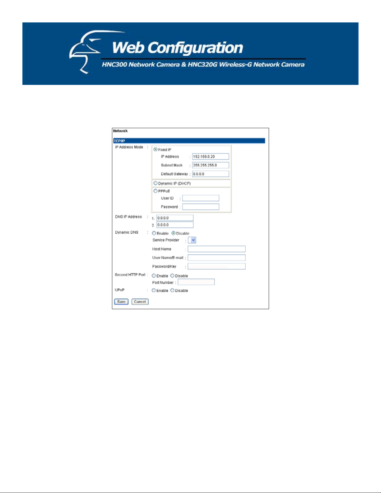
TCP/IP:
x IP Address Mode: This field provides you with three options. They are as follows:
Fixed IP – You can select this option and enter the IP address directly. The default settings are:
x IP Address – 192.168.0.20
x Subnet Mask – 255.255.255.0
x Default Gateway – 0.0.0.0
Dynamic Address (DHCP) – If your network uses a DHCP server, you may select this option. According to
this setting, the camera will automatically be assigned an IP address from the DHCP server. Once you click
“Save” at the bottom of the page, wait for the camera to reboot (this could take up to one minute). After the
camera has finished rebooting, you can locate the camera’s new IP address via the camera’s Setup Wizard
utility. The new IP address should appear under the “Current IP Address” heading in the utility. (If you have
multiple cameras on the network, you may need to test the newly assigned IP addresses to locate the camera
you have just configured.)
PLEASE NOTE: If you want to be certain of your camera’s IP address at all times, “Fixed IP” is the preferred
option.
28
Page 29
PPPoE – If your application requires a direct connection from an ADSL modem through the camera’s RJ-45
LAN port, click this option and enter the User ID and Password into the respective boxes. (You should have an
ISP PPPoE account.) The camera will get an IP address from the ISP when it starts up.
x DNS IP Address: A DNS (Domain Name System) server is an Internet service that translates domain names
into IP addresses. Enter at least one DNS IP Address in this field.
x Dynamic DNS: The Dynamic DNS service allows you to alias a dynamic IP address to a static hostname in
any of the domains, allowing your computer to be accessed more easily from various locations on the Internet.
x Second HTTP Port: The default port for communication is via port 80, and you can change it according to
your network configuration. Select Enable from the option and enter the desired port number in the
appropriate box.
The Second HTTP Port field allows you to open a second port for the network camera. This will permit users’
routers to support multiple network cameras. By default, Port 80 (on the router) is always open for network
camera web server access.
For example, assume you have five network cameras to be installed, with the following IP addresses:
192.168.0.101
192.168.0.102
192.168.0.103
192.168.0.104
192.168.0.105
You can open the second port for each network camera, from port 81 to Port 85, as illustrated below:
Internet Camera 1 – IP 192.168.0.101, second web port 81
Internet Camera 2 – IP 192.168.0.102, second web port 82
Internet Camera 3 – IP 192.168.0.103, second web port 83
Internet Camera 4 – IP 192.168.0.104, second web port 84
Internet Camera 5 – IP 192.168.0.105, second web port 85
You also need to setup your router for Port Mapping.
Port 81 map to 192.168.0.101
Port 82 map to 192.168.0.102
Port 83 map to 192.168.0.103
Port 84 map to 192.168.0.104
Port 85 map to 192.168.0.105
Save/Cancel:
After making sure that all settings in the System are correct, click on the “Save” button to store the settings for
the network camera. You can alternatively click on the “Cancel” button to restore all settings to the values last
saved to or retrieved from the network camera.
x UPnP: UPnP is the architecture for pervasive peer-to-peer network connectivity of intelligent appliances and
PCs of all form factors. Check the Enable option to enable the function on your camera.
29
Page 30
User
Click on User to the right of the text “Internet Camera” to add, edit and delete users for your camera.
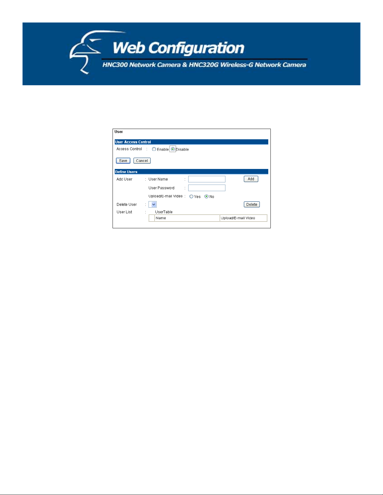
User Access Control:
x Access Control: The administrator has the authority to give specific users permission to control the device and
make configuration changes by selecting Enable or Disable. The default setting is Disable. When the “Access
Control” setting is set to “Disable” for a specific user, that user will only be able to view the image, and will
not be able to make any configuration changes to the device.
Define Users: Use this field to add or delete users for your camera.
x Add User: Enter the user name in this box, and enter the password that was assigned by the administrator for
this user. The maximum password length is 8 (printable ASCII) characters.
The administrator has the authority to give specific users permission to control the Upload/E-mail Video
control by selecting Yes or No to activate the Upload/E-mail Video.
To add a new user’s name, enter the necessary information first and click the Add button.
x Delete User: Select the user you want to delete from the pull-down menu, and then click the Delete button.
x User List: This list displays the camera’s current user status.
30
Page 31

DateTime
Click on DateTime to right of the text “Internet Camera” to set up the time and date for your camera.
Date & Time: You can set up the time and date automatically by selecting the Synchronized with Time Server
option, or manually in the Set Manually section.
x Synchronized with Time Server: Select this option to set the time according to the GMT setting. The time
will be synchronized every 10 minutes. When selecting this option, you have to enter the required information
in the following fields:
IP Address – Enter the IP Address of the Time Server in this box.
Protocol – You can select from two options, NTP or Time, to link with the Time Server. The default setting is
NTP.
TimeZone – Select the time zone for the region from the pull-down menu.
x Set Manually: Select this option to set the time manually. The system administrator must manually enter the
date and time in the respective field.
31
Page 32

Upload
Click on Upload to the right of the text “Internet Camera” to set up the configuration for the FTP server, time schedule,
and manual operation.
FTP Server: This field contains the following six basic settings for your FTP server.
x Host Address: The IP Address of the target FTP server.
x Port Number: The standard port number for the FTP server is Port 21, which is also the default setting. If the
FTP server uses a different port, please confirm this with the IT manager.
x User Name: Enter the user name in this field.
x Password: Enter the user password in this field to login into the FTP server.
x Directory Path: Enter an existing folder name in this field, and the images will be uploaded to the given folder.
x Passive Mode: This function depends on your FTP server. Please check with your IT manager if the FTP
server uses passive mode. The default setting is No.
32
Page 33

Time Schedule: Select the “Enable upload video to FTP server” option and enter the relevant information,
such as the schedule, video frequency and base file name.
x Schedule: You can 1.) Choose Always to always upload the video to the FTP server, or 2.) Set a Schedule to
manage the uploading task. In the Schedule option, you can set the Day and Time Period options.
x Video Frequency: There are two ways to set the video frequency: 1.) Set Auto/1/2/3 frames per second, or 2.)
Set the time, in seconds, for every frame.
x Base File Name: Enter the file name to make sure that the images are saved using this base file name.
x File: Since it is likely that you will upload more than one image to the FTP server, you can choose the filing
rule, including Overwrite, Date/Time Suffix, and set up the Sequence Number.
Manual Operation: When you click the Upload Video button in the video viewing screen, it will start to
upload the image. The settings refer to the Base File Name and File information above.
33
Page 34

Email
Click on E-mail to the right of the text “Internet Camera” to configure the E-mail account, time schedule and manual
operation settings.
E-mail Account: This field contains the following six basic E-mail settings.
x SMTP Server Address: SMTP (Simple Mail Transfer Protocol) is a protocol for sending e-mail messages
between servers. You need to input the mail server address in this field.
x Sender e-mail Address: Enter the e-mail address of the user who will send the e-mail.
x Receiver e-mail Address: Enter the e-mail address of the user who will receive the e-mail.
x User Name: Enter the user name in this field.
x Password: Enter the user password in this field to log into the mail server.
Time Schedule: Select the “Enable-mail video to e-mail account” option to set a schedule to send e-mail.
Please refer to the instructions in the “Upload” section. The Interval option is to define the time interval
between the sending of successive images.
Manual Operation: When you click the E-mail Video button in the video viewing screen, it will start to e-
mail images. The Interval option is to define the time interval between the sending of successive images.
34
Page 35

System Administration: Tools
The Tools window contains commands for running basic tests, as well as for upgrading and restarting the camera. Click
Tools in the top menu bar and the Tools window will appear as below:
FTP Server Test
Click on FTP Server Test to the right of the text “Internet Camera” to test your FTP server settings.
Test FTP Server: Click the Test button to test the FTP server settings.
E-mail Test
Click on E-mail Test to the right of the text “Internet Camera” to test your e-mail account.
Test E-mail Account: Click the Test button to test the e-mail account settings you provided.
35
Page 36

Reset
“Do you really want to reset this device?” Click the Yes button for this option, and you can restart the camera. (This is
equivalent to physically turning the camera off and on again; your settings will stay saved. If you do not want to reset the
camera, exit this window without clicking Yes.
Factory Reset
“Do you want to restore this device to factory default setting?” If you click the Yes button for this option, you can restore
all the factory default settings for the camera. If you do not want to restore the factory settings, exit this window without
clicking Yes. Please NOTE that you have to configure the network settings again after a Factory Reset.
Firmware Upgrade
When a new firmware upgrade is available, you can upgrade it through this window. Click the “Browse…” button to
locate the firmware file, and then click Update to start upgrading.
36
Page 37

Backup
Click the Backup item in the left column to back up the current configuration.
Backup Device Configuration to File: “Do you want to backup the configuration to file?” Click the Backup
button from this option, and you can save the current configuration to file.
Restore Device Configuration from File: You can restore the device configuration from a saved file in the
computer. Click the “Browse…” button to locate the file, and then click Restore to start restoring.
37
Page 38

System Administration: Help
The Help window provides the camera’s most basic information. Click Help in the top menu bar and the Help window
will appear as below:
About
Displays the camera’s model name and version.
Once the configuration is completed, click Home to return to the Welcome screen and select the desired video viewing
option either through ActiveX Mode or Java Mode as described in the next section.
Then, position the camera in the desired location. Then, adjust the camera focus. You can do this manually by turning
the lens clockwise or counter-clockwise until you achieve the desired image clarity. Please refer to Appendix F for more
detailed instructions.
38
Page 39

HNC320G
System Administration: Management
The Management window contains the information you will need to configure your camera. Click the items in the menu
bar to the right of the text “Internet Camera” to view your settings, including: System, Video, Wireless, Network, and
User.
System
Click System to the right of the text “Internet Camera” to display the device status of your camera.
x Device Status: The camera’s vital information, including the Camera Name, Location, Model, Firmware
Version, MAC Address and IP Address, can be found in this field.
x Ethernet Status: You can monitor the camera’s network status in this field, including Link (network
connection), Speed, and the Duplex mode.
39
Page 40

Video
Click Video to the right of the text “Internet Camera” to display your camera’s video configuration information.
x Video Status: The camera’s video configuration information, including the Video Resolution, Compression
Rate, Frame Rate, Frame Size and IP Address, can be found in this field.
Wireless
Click on Wireless to the right of the text “Internet Camera” to display the wireless LAN information.
x Wireless Status: The items in this field display the wireless LAN information, such as the Connection
Mode (Infrastructure or Ad-Hoc), Link status, SSID, Channel, Transmission Rate, and WEP Encryption.
40
Page 41

Network
Click Network to the right of the text “Internet Camera” to display the camera’s network status information.
x Network Status: The items in this field display the camera’s network status information, such as the IP
Address, Subnet Mask, Default Gateway, Primary DNS Address, Secondary DNS Address, Dynamic DNS,
Secondary HTTP Port, and UPnP.
User
Click User to the right of the text “Internet Camera” to display the user(s) information.
x Active Users: The items in this field display the user information, including the user IP address, Name,
and Date & Time.
41
Page 42

System Administration: Configuration
The Configuration window contains commands for settings that are required for inputting key details to set up the
camera for operation. Click Configuration in the top menu bar and the Configuration window will appear as below:
System
Click on System to the right of the text “Internet Camera” to adjust your camera’s basic configuration settings.
System Setting: In this field, you can configure your camera’s basic settings.
42
Page 43

x Camera Name: This field is used to enter a descriptive name for the device. The default setting for the
Camera Name is CS-xxxxxx, where “xxxxxx” constitutes the last six digits of the device’s MAC Address. The
maximum length is 32 characters (printable ASCII).
x Location: This field is used to enter a descriptive name for the camera’s location.
x Admin: The fields in this section are used to enter the administrator’s name (“Admin ID”) and password. The
administrator’s ID and password will allow the user to access and configure the System Administration settings.
Be sure to enter the password twice to confirm the details, once in the Admin Password field and again in the
Confirm Password field.
The default settings for both the administrator user name and password are blank (or null string). The
administrator name (“Admin ID”) has a maximum length of 12 (printable ASCII) characters and the
administrator password has a maximum length of 8 (printable ASCII) characters.
It is highly recommended that you set the Admin ID and Admin Password as soon as possible to enable
security options for the camera.
NOTE: If you would like to create a user account that only has access to the video image, but not the system
administration settings, you can do this in the “User” page of the Configuration section. Instructions on how to
create such a user are provided in the pages that follow.
x LED Control: This option allows users to set up the LEDs, as desired. This feature provides flexibility when
surveillance activity is ON.
There are three options, and they are as follows:
Power - Steady On
Normal
OFF
Dummy
Link - Steady On
Note: When there is LAN activity, the LED
indicator will flash steadily.
Power - LED indicator is off.
Link – LED indicator is off.
Power - Steady On
Link - Steady On, with random flashing.
The default setting for the LED control is Normal. When you have configured the LED controls, the correct
illumination will set after 1 minute.
43
Page 44

Video
Click Video to the right of the text “Internet Camera” to configure the camera’s video settings.
Video Setting: In this field, you can configure the camera’s basic video settings.
x Video Resolution: Select the desired video resolution format:
x Compression Rate:
Select the desired compression rate. You will have five levels to choose from,
160 x 120, 320 x 240 (default), or 640 x 480.
ranging from Very Low to Very High. A higher video compression rate will generate a more
compact file size with poorer video quality, and vise-versa. The default setting is Medium.
x Frame Rate: Select the desired frame rate. The default setting is Auto for an optimal frame rate.
x Brightness Control: Adjust the brightness level; the default setting is 64.
x Contrast Control: Adjust the contrast level; the default setting is 64.
x Saturation Control: Adjust the saturation level; the default setting is 64.
x Light Frequency: Adjust the light frequency to suit your area of operation. The options are: 50 Hz or 60 Hz
(60Hz is the default).
x Mirror: Select Horizontal Mirror to flip the image horizontally, or Vertical Mirror to flip the image vertically.
x Anti-Flicker: If you capture a flickering image because of the environment factor (for example, from
the intense light from a lamp), please select this item to solve the problem.
44
Page 45

Wireless
Click on Wireless to the right of the text “Internet Camera” to configure the wireless LAN settings for your wireless
camera.
Wireless Interface
x Connection Mode: Use this option to determine the type of wireless communication for your camera. There
are two choices: Infrastructure mode and Ad-Hoc mode. The default setting is Infrastructure.
x SSID: The SSID (Service Set Identifier) is the name assigned to the wireless network. Clicking on “Site
Survey” will auto-detect and display the SSID of the wireless network in this box (it displays default initially).
This default setting will let the camera connect to ANY access point under the infrastructure network mode.
To connect the camera to a specific access point on the network, please make sure to set the SSID of the
camera to correspond with the access point’s SSID for communication. Type any string up to 32 characters
long (spaces, symbols, and punctuation are not allowed) in the SSID box.
45
Page 46

To connect the camera to an Ad-Hoc wireless workgroup, make sure that you set the same wireless channel
and SSID to match with the PC/Notebook’s configuration for direct wireless communication.
x Wireless Channel: This pull-down menu allows you to select the appropriate wireless channel for
communication. A "channel" is a range of frequencies to be used in communication between the camera and
access point in Infrastructure mode, or the camera and PC/Notebook in Ad-Hoc mode. Select the appropriate
channel from the list provided (depending on the regulatory region where the unit is sold). The default setting
is at channel 11.
x Transmission Rate: Select the data transmit rate from this pull-down menu. The default setting is Fully
Automatic.
WEP Encryption
x WEP Encryption: Wireless network communications can be intercepted easily. WEP (Wired Equivalent
Privacy) is an encryption method specified by the IEEE 802.11g standard to make any intercepted
communications extremely difficult to interpret by unauthorized parties. The default setting for this option is
Disable. But it is recommended that you either enable WEP encryption or utilize the more advanced form of
encryption, WPA-PSK. The WPA-PSK settings are described in the section near the bottom of this page.
x WEP Key Format: To enable WEP Encryption, you should decide the encryption format first by selecting the
ASCII or HEX option, and then input the WEP key (in the following Key 1 - 4 box).
ASCII input format:
ASCII format causes each character you type to be interpreted as an eight-bit value. All
unaccented upper- and lower-case Western European characters that can be input through your
keyboard's typing zone are valid. To setup a 64-bit WEP key, input 5 ASCII characters. For
example, ‘12345’. To setup a 128-bit WEP key, input 13 ASCII characters. For example,
‘1234567890123’. These character counts result in bit counts of 40 and 104 respectively; the
camera will automatically pad your input to a bit count of 64 or 128.
HEX input format:
Hex format causes each pair of characters you type to be interpreted as an eight-bit value in
hexadecimal (base 16) notation. Only the digits 0 through 9 and the letters A through F (in upper
or lower case) are valid. To setup a 64-bit WEP key, input 10 characters in HEX format. For
example, ‘3132333435’ (which is the same as an ASCII input of ‘12345’). To set up a 128-bit
WEP key, input 26 characters in HEX format. For example, ‘31323334353637383930313233’,
(which is the same with ASCII input ‘1234567890123’). These character counts result in bit
counts of 40 and 104, respectively; the wireless network camera will automatically pad your input
to a bit count of 64 or 128.
x Encrypt Data Transmissions Using: Use this pull-down menu to decide whether to use Key 1, 2, 3 or 4 for
encryption).
x WPA-PSK: This item is used to secure your wireless network in pre-shared key mode (8-63 ASCII or 64 HEX
characters). If you enable this function, each user must enter a pass phrase to access the network.
46
Page 47

Advanced Setting: In this field, you can configure more advanced settings.
x Beacon Interval: This option defines the time interval between two images sent in succession.
x Preamble: A preamble is a signal used in wireless environments to synchronize the transmission timing,
including Synchronization and Start frame delimiter. Please NOTE that if you want to change the Preamble
type from Long to Short, you will need to check the access point’s settings.
x Authentication Type: Open System communicates the key across the network. Shared Key allows
communication only with other devices with identical WEP settings. The default setting is Both.
47
Page 48

Network
Click on Network to the right of the text “Internet Camera” to configure the LAN settings for your camera.
TCP/IP:
x IP Address Mode: This field provides you with three options. They are as follows:
Fixed IP – You can select this option and enter the IP address directly. The default settings are:
x IP Address – 192.168.0.20
x Subnet Mask – 255.255.255.0
x Default Gateway – 0.0.0.0
Dynamic Address (DHCP) – If your network uses a DHCP server, you may select this option. According to
this setting, the camera will automatically be assigned an IP address from the DHCP server. Once you click
“Save” at the bottom of the page, wait for the camera to reboot (this could take up to one minute). After the
camera has finished rebooting, you can locate the camera’s new IP address via the camera’s Setup Wizard
utility. The new IP address should appear under the “Current IP Address” heading in the utility. (If you have
multiple cameras on the network, you may need to test the newly assigned IP addresses to locate the camera
you have just configured.)
PLEASE NOTE: If you want to be certain of your camera’s IP address at all times, “Fixed IP” is the preferred
option.
48
Page 49

PPPoE – If your application requires a direct connection from an ADSL modem through the camera’s RJ-45
LAN port, click this option and enter the User ID and Password into the respective boxes. (You should have an
ISP PPPoE account.) The camera will get an IP address from the ISP when it starts up.
x DNS IP Address: A DNS (Domain Name System) server is an Internet service that translates domain names
into IP addresses. Enter at least one DNS IP Address in this field.
x Dynamic DNS: The Dynamic DNS service allows you to alias a dynamic IP address to a static hostname in
any of the domains, allowing your computer to be accessed more easily from various locations on the Internet.
x Second HTTP Port: The default port for communication is via port 80, and you can change it according to
your network configuration. Select Enable from the option and enter the desired port number in the
appropriate box.
The Second HTTP Port field allows you to open a second port for the network camera. This will permit users’
routers to support multiple network cameras. By default, Port 80 (on the router) is always open for network
camera web server access.
For example, assume you have five network cameras to be installed, with the following IP addresses:
192.168.0.101
192.168.0.102
192.168.0.103
192.168.0.104
192.168.0.105
You can open the second port for each network camera, from port 81 to Port 85, as illustrated below:
Internet Camera 1 – IP 192.168.0.101, second web port 81
Internet Camera 2 – IP 192.168.0.102, second web port 82
Internet Camera 3 – IP 192.168.0.103, second web port 83
Internet Camera 4 – IP 192.168.0.104, second web port 84
Internet Camera 5 – IP 192.168.0.105, second web port 85
You also need to setup your router for Port Mapping.
Port 81 map to 192.168.0.101
Port 82 map to 192.168.0.102
Port 83 map to 192.168.0.103
Port 84 map to 192.168.0.104
Port 85 map to 192.168.0.105
Save/Cancel:
After making sure that all settings in the System are correct, click on the “Save” button to store the settings for
the network camera. You can alternatively click on the “Cancel” button to restore all settings to the values last
saved to or retrieved from the network camera.
x UPnP: UPnP is the architecture for pervasive peer-to-peer network connectivity of intelligent appliances and
PCs of all form factors. Check the Enable option to enable the function on your camera.
49
Page 50

User
Click on User to the right of the text “Internet Camera” to add, edit and delete users for your camera.
User Access Control:
x Access Control: The administrator has the authority to give specific users permission to control the device and
make configuration changes by selecting Enable or Disable. The default setting is Disable. When the “Access
Control” setting is set to “Disable” for a specific user, that user will only be able to view the image, and will
not be able to make any configuration changes to the device.
Define Users: Use this field to add or delete users for your camera.
x Add User: Enter the user name in this box, and enter the password that was assigned by the administrator for
this user. The maximum password length is 8 (printable ASCII) characters.
The administrator has the authority to give specific users permission to control the Upload/E-mail Video
control by selecting Yes or No to activate the Upload/E-mail Video.
To add a new user’s name, enter the necessary information first and click the Add button.
x Delete User: Select the user you want to delete from the pull-down menu, and then click the Delete button.
x User List: This list displays the camera’s current user status.
50
Page 51

DateTime
Click on DateTime to right of the text “Internet Camera” to set up the time and date for your camera.
Date & Time: You can set up the time and date automatically by selecting the Synchronized with Time Server
option, or manually in the Set Manually section.
x Synchronized with Time Server: Select this option to set the time according to the GMT setting. The time
will be synchronized every 10 minutes. When selecting this option, you have to enter the required information
in the following fields:
IP Address – Enter the IP Address of the Time Server in this box.
Protocol – You can select from two options, NTP or Time, to link with the Time Server. The default setting is
NTP.
TimeZone – Select the time zone for the region from the pull-down menu.
x Set Manually: Select this option to set the time manually. The system administrator must manually enter the
date and time in the respective field.
51
Page 52

Upload
Click on Upload to the right of the text “Internet Camera” to set up the configuration for the FTP server, time schedule,
and manual operation.
FTP Server: This field contains the following six basic settings for your FTP server.
x Host Address: The IP Address of the target FTP server.
x Port Number: The standard port number for the FTP server is Port 21, which is also the default setting. If the
FTP server uses a different port, please confirm this with the IT manager.
x User Name: Enter the user name in this field.
x Password: Enter the user password in this field to login into the FTP server.
x Directory Path: Enter an existing folder name in this field, and the images will be uploaded to the given folder.
x Passive Mode: This function depends on your FTP server. Please check with your IT manager if the FTP
server uses passive mode. The default setting is No.
52
Page 53

Time Schedule: Select the “Enable upload video to FTP server” option and enter the relevant information,
such as the schedule, video frequency and base file name.
x Schedule: You can 1.) Choose Always to always upload the video to the FTP server, or 2.) Set a Schedule to
manage the uploading task. In the Schedule option, you can set the Day and Time Period options.
x Video Frequency: There are two ways to set the video frequency: 1.) Set Auto/1/2/3 frames per second, or 2.)
Set the time, in seconds, for every frame.
x Base File Name: Enter the file name to make sure that the images are saved using this base file name.
x File: Since it is likely that you will upload more than one image to the FTP server, you can choose the filing
rule, including Overwrite, Date/Time Suffix, and set up the Sequence Number.
Manual Operation: When you click the Upload Video button in the video viewing screen, it will start to
upload the image. The settings refer to the Base File Name and File information above.
53
Page 54

Email
Click on E-mail to the right of the text “Internet Camera” to configure the E-mail account, time schedule and manual
operation settings.
E-mail Account: This field contains the following six basic E-mail settings.
x SMTP Server Address: SMTP (Simple Mail Transfer Protocol) is a protocol for sending e-mail messages
between servers. You need to input the mail server address in this field.
x Sender e-mail Address: Enter the e-mail address of the user who will send the e-mail.
x Receiver e-mail Address: Enter the e-mail address of the user who will receive the e-mail.
x User Name: Enter the user name in this field.
x Password: Enter the user password in this field to log into the mail server.
Time Schedule: Select the “Enable-mail video to e-mail account” option to set a schedule to send e-mail.
Please refer to the instructions in the “Upload” section. The Interval option is to define the time interval
between the sending of successive images.
Manual Operation: When you click the E-mail Video button in the video viewing screen, it will start to e-
mail images. The Interval option is to define the time interval between the sending of successive images.
54
Page 55

System Administration: Tools
The Tools window contains commands for running basic tests, as well as for upgrading and restarting the camera. Click
Tools in the top menu bar and the Tools window will appear as below:
FTP Server Test
Click on FTP Server Test to the right of the text “Internet Camera” to test your FTP server settings.
Test FTP Server: Click the Test button to test the FTP server settings.
E-mail Test
Click on E-mail Test to the right of the text “Internet Camera” to test your e-mail account.
Test E-mail Account: Click the Test button to test the e-mail account settings you provided.
55
Page 56

Reset
“Do you really want to reset this device?” Click the Yes button for this option, and you can restart the camera. (This is
equivalent to physically turning the camera off and on again; your settings will stay saved. If you do not want to reset the
camera, exit this window without clicking Yes.
Factory Reset
“Do you want to restore this device to factory default setting?” If you click the Yes button for this option, you can restore
all the factory default settings for the camera. If you do not want to restore the factory settings, exit this window without
clicking Yes. Please NOTE that you have to configure the network settings again after a Factory Reset.
Firmware Upgrade
When a new firmware upgrade is available, you can upgrade it through this window. Click the “Browse…” button to
locate the firmware file, and then click Update to start upgrading.
56
Page 57

Backup
Click the Backup item in the left column to back up the current configuration.
Backup Device Configuration to File: “Do you want to backup the configuration to file?” Click the Backup
button from this option, and you can save the current configuration to file.
Restore Device Configuration from File: You can restore the device configuration from a saved file in the
computer. Click the “Browse…” button to locate the file, and then click Restore to start restoring.
57
Page 58

System Administration: Help
The Help window provides the camera’s most basic information. Click Help in the top menu bar and the Help window
will appear as below:
About
Displays the camera’s model name and version.
Once the configuration is completed, click Home to return to the Welcome screen and select the desired video viewing
option either through ActiveX Mode or Java Mode as described in the next section.
Then, position the camera in the desired location. Then, adjust the camera focus. You can do this manually by turning
the lens clockwise or counter-clockwise until you achieve the desired image clarity. Please refer to Appendix F for more
detailed instructions.
58
Page 59

View Image - ActiveX Mode
To view video images from the web browser, click on “View Image – ActiveX Mode” on the welcome screen to access
the video images from Internet Explorer, as illustrated below:
Video Server Name
Location
Date/Time
Camera Name* - The Camera name will be display when the Camera Name field is entered in the Web Configuration
setting under “System”
Location**- The location of the Internet Camera will be displayed when the Location field is entered in the Web
Configuration settings under “System”.
Date/Time***- The date/time of the video server will show the date and time which come from time server or you set
manually.
Note:
Please refer to the appendix on how to install ActiveX.
1. Install to the Web Server
2. Install to your Local PC
In the View Image – ActiveX Mode you are allowed two output trigger options and one image upload option. Just click
on the desired selection “ON” or “OFF” to utilize the options for each of the functions.
Note 1:
Administrator has the authority to set the email image functions through the setting in the “E-mail” of System
Administration menu bar.
Note 2:
The Administrator has the authority to allow user’s to set the image upload functions through the setting in the “Upload”
of System Administration menu bar.
59
Page 60

View Image – Java Mode
Click on “View Image – Java Mode” from the Welcome screen to access the video images from the Internet Explorer or
Netscape browser as illustrated below:
Video Server Name
Location
Date/Time
Camera Name* - The camera name will be displayed when the Camera Name field is entered in the Web Configuration
setting under “Configuration”
Location** - The location of the Internet Video Server will be displayed when the Location field is entered in the Web
Configuration settings under “System”.
Date/Time***- The date/time of the wireless internet video server will show the date and time which come from time
server or you set manually.
In the View Image – ActiveX Mode you are allowed two output trigger options and one image upload option. Just click
on the desired selection “ON” or “OFF” to utilize the options for each of the functions.
NOTE:
1. Please refer to the appendix on how to install ActiveX,
including: 1.) Installing to the Web Server, and 2.) Installing to
your Local PC.
2. The administrator has the authority to set the upload video
function through the setting in the Upload option under
Configuration.
2. The administrator has the authority to set the e-mail video
function through the setting in the E-mail option under
Configuration.
60
Page 61

The HNC300/HNC320G can be utillzed in wide variety of applications. The cameras are all-in-one devices and can be
attached directly to an Ethernet or Fast Ethernet network. The HNC320G also supports the IEEE 802.11b/g standard.
The cameras are standalone systems with built-in CPUs, along with web-based solutions that allow the devices to transmit
high quality video images for monitoring purposes. They can be managed remotely, and can be accessed and controlled
from any PC over the Intranet or Internet via a web browser. With the IPView SE application, you can further expand the
scope of the HNC300/HNC320G.
This chapter will provide typical applications for the HNC300/HNC320G and IPView SE software, and includes some
basic knowledge to assist in the installation and configuration of the cameras.
Applications
x Monitoring of local and remote places and objects such as construction sites, hospitals, amusement parks, schools
and day-care centers via a web browser.
x Using the IPView SE software application, you can capture single frame images or video images.
Home Applications
SOHO Wireless
Internet Camera
SOHO
Internet Camera
61
Page 62

SOHO (Small Office, Home Office) Applications
SOHO
62
Page 63

Installation
Insert the CD-ROM into the CD-ROM drive to initiate the auto-run program. Once completed, a menu screen will
appear as follows:
63
Page 64

To install the IPView SE application, click on “Install IPView Software" to activate the installation procedure for the
application program.
Once executed, a prompt will appear and request the input of the desired language selection. Make the desired selection
and click on “OK” to continue.
The Welcome screen will appear. Click on the “Next” button to proceed with the installation.
64
Page 65

The License Agreement prompt will appear, as below. Read the details carefully and click on the “Yes” button to
continue with the installation procedure.
A prompt will appear and in the Destination Location dialog box, you may click on “Next” to accept the recommended
destination location or click on “Browse” to select another location. After specifying the desired destination location,
click on “Next” to proceed.
65
Page 66

The Select Program Folder prompt will appear, providing information on where the IPView SE application will be located.
Click on “Next” to continue. If you wish to modify your settings, click on “Back” to return to the previous screens.
Please wait until one of the two dialog boxes appears, and then select “Yes, I want to restart my computer now” and click
on the “Finish” button to restart the computer to complete the installation procedure.
66
Page 67

Or click on the “Finish” button to complete the installation procedure.
After successfully installing the IPView SE software application, the application program for the HNC300/HNC320G is
automatically installed to \Programs\Files Directory.
To start running IPView SE, click on Start Menu/Programs/IPView SE /IPView SE.
Once you log in, the IPView SE application will execute and the application’s interface will appear as below in the default
List View format:
67
Page 68

This section describes the operation of the IPView SE application User Interface with detailed explanations of procedures
for using the application. IPView SE is responsible for management of the preview, configuration, and search of each
camera. It incorporates a user-friendly interface for ease of control and navigation, as illustrated below.
IPView SE Control Panel
Minimum
Close
Play
Scan
About
Combine
System Config Add Camera
Minimum – Minimizes the control panel.
Close – Closes the control panel.
Play – Plays back the recording file.
.
Scan – Searches for all network cameras available on the LAN. (At minimum, this function will locate any
Hawking cameras that have the code “HCVT” located beneath the UPC code on the product packaging or within
the serial number that appears on the white sticker label of the product. However, this function may be able to
locate other network cameras on the LAN that do not have this code.)
Combine – Combines all display windows into one window.
About – Displays information about the IPView SE application.
68
Page 69

How to Add a Camera
Add Camera
Add Camera
Click on Add Camera icon to add a new camera. An Add Camera dialog box will appear, as illustrated below.
You can enter the IP Address of the camera in the specified field and click the “Add” icon to add a new camera.
Note 1:
1. If you want to add a camera via the Internet, you must key in a physical IP Address.
2. When the camera is installed behind the router/gateway and the Open Second Port of the camera /Port Forwarding of
the router/gateway function is enabled, the Gateway IP address must be entered with the Port Number, as below:
69
Page 70

3. At the same time, the Gateway IP address can be replaced by URL as below:
4. If you incorrectly input the IP Address you wish to add, a dialog box will appear to notify you of the error.
If you are unsure of the camera’s IP address, you can click on the “Browse” button, and the Browse Camera dialog box
will appear with a blank screen, as illustrated below.
You must select the camera and click on the “Add” button to add a new camera. The Add Camera dialog box will
appear once again, this time with the IP Address entered. Click on the “Add” icon and the camera will be automatically
added into IPView SE list view format.
70
Page 71

If the Login Camera dialog box appears, make sure to enter the correct User Name and Password and click on the
“OK” button and the camera will be added into IPView SE in list format. If the User Name and Password are entered
incorrectly, the camera will not be added into IPView SE.
The above dialog box will appear only if the administrator has already set the User Name and Password during the Web
Configuration setting.
If you forget to highlight the camera you wish to add, a dialog box will appear to notify you of the error.
Make sure to save any changes you have made to keep the information updated.
Note 2:
You can only add one camera at a time.
When the user adds the network camera, four icons will appear: “Assign IP to Camera”, “Connect / Disconnect”, “Erase”,
“Extra Information”
71
Page 72

Camera Config
t
Motion record
Assign IP Address to Camera
Schedule record
Connect / Disconnec
Manual record
Erase Extra Information
How to Change Cameras
Assign IP of New Camera
To change cameras, click the “Assign IP of Camera” button. An Assign IP of Camera dialog box will appear as
illustrated below:
You must select the camera and click the Add button to add a new camera.
72
Page 73

How to Connect/Disconnect the Image
Connect the Image - click on the “Connect/Disconnect” button and the preview screen will appear with the video
image.
Minimum – Minimizes the display screen of the network camera.
Maximum – Maximizes the display screen of the network camera.
Close – Closes the display screen of the network camera.
Always on top – The display screen will always be on top of the window.
Wake up control panel – Opens the control panel again when it is closed.
Color setting – Adjusts the color setting of the image.
View list – Checks the network camera’s event list.
Snapshot – Commands the network camera to take a snapshot picture.
Rotate image – Rotates the image of the network camera.
Zoom - Click to zoom in and out on the camera’s picture. (Note: The HNC300 and HNC320G feature digital
zoom, not true optical zoom.)
73
Page 74

Disconnect the Image – Click on the “Connect/Disconnect button again to disconnect the camera.
How to Delete a Camera
Erase Camera – To delete a camera, you must select the camera to delete from the IPView SE control panel.
Then click on the “Erase Camera” button. After deleting, the IPView SE control panel will appear as below.
74
Page 75

Extra Information
Extra Information – Lists camera information.
How to Adjust the Property Setting
System Configure – The dialog box below will appear.
Log Storage:
1. Single HDD Reserve Space:
The “Single HDD Reserve Space” permits reserved space by memory size from 500 MB to 1000 MB.
75
Page 76

2. Split Recording File
From the “Split Recording File” you can adjust the file size for recording the video images. (The default size for
file size recording is 5MB). If the recorded video files reach the file size, video images will be recorded into
another file automatically.
By File Size - permits recording by file memory size from 5 MB to 50 MB.
3. Storage List
This defines the file path to save the image.
The software will create a camera name folder as the “Storage List”, which is allowed to create up to four File Paths.
Recycle:
When you select “Recycle”, the system will recycle the HDD space once the space becomes less than the size defined.
The defined size can be from 200 MB to 50000 MB.
Proxy Server:
This can be selected to support a “Proxy server”.
Camera Scan Delay:
This allows full screen display for each camera one by one. The time interval for each camera can be from 1 second to 20
seconds.
Camera Configure – Click on this button to activate the Camera Setting, Motion Setting, and Update Firmware
icons.
Camera Setting – Refer to the “Web Configuration” section.
Camera Setting
Motion Setting
Update Firmware
76
Page 77

Motion Setting – Adjusts the sensitivity level and selects the Invoke Alarm options to work with the motion
detection function (if available). Along with Alarm Beep, the Send Email function can also be enabled when
motion is detected. The user can define the time interval to send emails.
Mail Server: Mail Server IP or name.
Mail From: E-Mail Address of sender.
Mail To: E-Mail Address of receiver.
Subject: Can be any information the user chooses.
User Name: Enter the user name in this field.
Password: Enter the user password in this field to log into the receiver’s mail server.
Interval Time: The time interval to send the next E-Mail (the units are in seconds).
77
Page 78

Update Firmware
Click on the “Update” button and enter the File Path. The firmware will then be updated automatically.
If you are unsure of the File path, you can click on the “Browse” icon. The Browse dialog box will appear with a blank
screen, as illustrated below.
Warning
During the firmware update process, please make sure no
interruptions occur, as it may cause serious damage to the camera.
78
Page 79

How to Adjust the Recording Settings
There are three ways to start recording the image: Motion Record, Schedule Record & Manual Record.
Motion Record – Recording is triggered when motion is detected (if the motion detection feature is available).
You can adjust the sensitivity level and choose the warning options when motion is detected from the motion
setting.
Schedule Record – Triggers recording as scheduled. The schedule is set by date or weekday.
Manual Record – Triggers manual recording.
79
Page 80

A. Frequently Asked Questions
Regarding Camera Features
Q: What is an Internet/Network Camera?
A: The HNC300/HNC320G is a standalone system that connects directly to an Ethernet or Fast Ethernet network. The
HNC320G also supports wireless transmission based on the IEEE 802.11b/g standard. It is different from a conventional
PC Camera in that the HNC300/HNC320G is an all-in-one system with built-in CPU and web-based solutions that
provide a low cost solution, which can transmit high quality video images for monitoring. The HNC300/HNC320G can
be managed remotely, and can be accessed and controlled from any PC/Notebook over the Intranet or Internet via a web
browser.
Q: What is the maximum number of users that can be allowed to access the HNC300/HNC320G simultaneously?
A: The maximum number of users that can log onto the HNC300/HNC320G at the same time is 64. Please keep in mind
that the overall performance of the transmission speed will slow down when many users are logged on simultaneously.
Q: What algorithm is used to compress the digital image?
A: The HNC300/HNC320G utilizes the JPEG image compression technology, thereby providing high quality images for
users. JPEG technology is utilized since it is a standard for image compression and can be applied to various web browser
sand application software without the need to install extra software.
For the HNC320G only:
Q: Can I change the wireless antenna that is attached to the HNC320G?
A: The wireless antenna can be changed for such purposes as extending the wireless transmission range. However,
please make sure that the connectors of the new antennas are of the SMA connector type. For a full listing of high
performance antennas that can be used to replace the standard antenna that has been included with the HNC320G, please
visit the Hawking website at:
www.hawkingtech.com
.
Q: What is the wireless transmission range for the HNC320G?
A: Generally, the wireless distance will reach up to 100 meters indoors and up to 300 meters outdoors. The range is
limited by the number of walls, ceilings, or other objects that the wireless signals must pass through. Typical ranges vary
depending on the types of materials and background Radio Frequency (RF) noise in your home or business and the
configuration setting of your network environment.
HNC300/HNC320G Installation
Q: Can the HNC300/HNC320G be used outdoors?
A: The HNC300/HNC320G is not weatherproof. Outdoor use is not recommended. In some cases, the camera can be
equipped with a weatherproof case to be used outdoors, but users are advised to use caution when choosing this option.
Q: What network cabling is required for the HNC300/HNC320G?
A: The HNC300/HNC320G uses Category 5 UTP cable for 10 Base-T and 100 Base-TX networking.
80
Page 81

Q: Can the HNC300/HNC320G be setup as a PC camera on the computer?
A: No, the HNC300/HNC320G is an Internet/Network Camera and can only be used on Ethernet and Fast Ethernet
networks. The HNC320G can also be used in wireless networks.
Q: Can the HNC300/HNC320G be connected on the network if it consists of only private IP addresses?
A: The HNC300/HNC320G can be connected to a LAN with private IP addresses.
Q: Can the HNC300/HNC320G be installed and function properly if a firewall exists on the network?
A: If a firewall exists on the network, port 80 is open for ordinary data communication. However, since the
HNC300/HNC320G transmits image data, the default port 8481 is also required. Therefore, it is necessary to open port
8481 on the network for remote users to access the HNC300/HNC320G.
B. Ping Your IP Address
The PING (Packet Internet Groper) command can determine whether a specific IP address is accessible by sending a
packet to the specific address and waiting for a reply. It can also provide a very useful tool to confirm if the IP address
conflicts with the HNC300/HNC320G on the network.
Follow the step-by-step procedure below to utilize the PING command. But first you must disconnect the
HNC300/HNC320G from the network.
Start a DOS window.
Type “ping a.b.c.d”, where “a.b.c.d” is the IP address of the network camera.
C. Troubleshooting
Given below are some helpful explanations to the causes of potential problems that might arise with the
HNC300/HNC320G.
Q: I cannot access the Internet Camera from a web browser.
A1: The possible cause might be the network camera’s IP Address if it conflicts with another device. To correct the
possible problem, you need to first disconnect the Internet Camera from the network. Then run the PING utility (follow
the instructions in Appendix B - PING Your IP Address).
A2: Another possible reason is the IP Address is located on a different subnet. To fix the problem, run the PING utility
(follow the instructions in Appendix B - PING Your IP Address). If the utility returns “no response” or similar, the
finding is probably correct, then you should proceed as follows:
In Windows 95/98/2000 and Windows NT, double-check that the IP Address of the camera is within the same subnet as
your workstation.
Click “Start”, “Setting”, “Control Panel”, and the “Network” icon.
Select TCP/IP from the “Network” dialog box, and from the “TCP/IP Properties” dialog box, click on “Specify an IP
address”.
81
Page 82

If the network camera is situated on a different subnet than your workstation, you will not be able to set the IP address
from this workstation. To verify, make sure the first three sections of the IP address of the network camera correspond to
the first three sections of the workstation. Thus, the IP address of the camera must be set from a workstation on the same
subnet.
A3: Other possible problems might be due to the network cable. Try replacing your network cable. Test the network
interface of the product by connecting a local computer to the unit, utilizing a standard crossover (hub to hub) cable. If
the problem still cannot be resolved, the network camera may be faulty.
Q: Why is the Power LED not lit continuously?
A: The power supply you are using may the source of the problem. Confirm that you are using the DC 5V power supply
that has been provided with the HNC300/HNC320G and verify that the power supply is well connected.
Q: Why does the Link LED not light up properly?
A1: There might be a problem with the network cable. To confirm that the cables are working, PING the address of a
know device on the network. If the cabling is OK and your network is reachable, you should receive a reply similar to the
following (…bytes = 32 time = 2 ms).
A2: The network device utilized by the Wireless Internet Camera is not functioning properly such as hubs or switches.
Confirm the power for the devices are well connected and functioning.
(For the HNC320G only)
A3: The wireless connection might be at fault. In ad-hoc mode, make sure the HNC320G
wireless channel and SSID are set to match the PC/Notebook wireless channel and SSID for direct communication.
Under infrastructure mode make sure the SSID on the PC/Notebook and the HNC320G must match with the Access
Point’s SSID.
Q: Why does the HNC300/HNC320G work locally but not externally?
A1: This might be caused by the firewall protection. You will need to check the Internet firewall with your system
administrator.
A2: The default router setting might be a possible reason. You will need to double-check if the configuration of the
default router settings is required.
Q: Why does a series of broad vertical white line appears throughout the image?
A: A likely issue is that the network camera’s CMOS (see Appendix G – Specifications) sensor becomes overloaded
when the light source is too bright, as can occur from direct exposure to sunlight or a halogen light. You need to
reposition the camera into a more shaded area immediately, as prolonged exposure will damage the CMOS sensor.
Q: The camera focus is poor. What can I do to fix this?
A1: The focus might not be correctly adjusted for the line of sight. You need to adjust the camera focus manually, by
turning the lens either in the clockwise or counterclockwise direction.
A2: There is no adaptor fitted with your C-type lens. If you have previously changed the supplied CS-type lens, you may
have unintentionally installed a C-type lens without fitting the adaptor first.
82
Page 83

Q: Noisy images occur. What can I do to fix this?
A1: The video images might be noisy if the HNC300/HNC320G is used in a very low light environment. To resolve this
issue, place the camera in a location with better lighting.
(For the HNC320G only)
A2: There might be wireless transmission interference. Make sure there are no other wireless
devices on the network that will affect the wireless transmission.
Q: The image quality is poor. How can I improve the image?
A1: A probable cause might be that the display properties are configured incorrectly on your desktop. You need to open
the Display Properties on your desktop and configure your display to show at least 65,000 colors (i.e., at least 16-bit).
Note:
Applying only 16 or 256 colors on your computer will produce dithering artifacts in the image.
A2: The configuration of the HNC300/HNC320G image display is incorrect. Through the Web Configuration Image
section, you need to adjust the image related parameters such as brightness, contrast, hue and light frequency. Please refer
to the Web Configuration section for detail information.
Q: There are no images available through the web browser.
A: The ActiveX control might be disabled. If you are viewing the images from Internet Explorer make sure ActiveX has
been enabled in the Internet Options menu. Alternatively, you can use the Java Applet for viewing the required images.
D. Upgrade Firmware
Users can upgrade the firmware via the IPView SE application. Select Camera>Properties and the Camera Property
dialog box will appear. Select the Tools tab and enter the full path of the firmware binary file name in the Update
Firmware field, or click on the “Browse” button to select the file. Once the firmware file is entered, click on the
“Update” button to proceed with the updating process. Once completed, click on the “OK” button, as illustrated below.
Warning: During the firmware update process, please make sure no interruptions occur as this could cause serious
damage to the HNC300/HNC320G.
83
Page 84

E. Time Zone Table
84
Page 85

F. Xplug Control Installation
Installation To Web Server
Important Information
It is highly recommended to install the Xplug Control
application to the Web Server for IE 5.0. It must be
installed to a Public Domain with a Fixed IP address.
1. Installation:
Copy the “xplug.ocx” file to any WEB Server table.
2. Setting (Configuration):
From the Web Configuration menu, select “System” and under the “Loading ActiveX From” input web server
location
http://www.web server location.com/
(
).
Once the settings are completed the user now is able to access the network camera from the web browser by selecting the
image view – ActiveX mode.
85
Page 86

Installation To Local PC
Insert the CD-ROM into the CD-ROM drive to initiate the auto-run program. Once completed, a menu screen will
appear, as follows:
To install the Xplug Control (ActiveX control), click on the "Install X Plug" button to activate the installation procedure
for the plug-in program.
Once executed, a prompt will appear and request the input of the desired language selection. Make the desired selection
and click on “OK” to continue.
86
Page 87

The Welcome screen will appear. Click on the “Next” button to proceed with the installation.
The License Agreement prompt will appear as below. Read the details carefully and click on the “Yes” button to continue
with the installation procedure.
Click on the “Finish” button to complete the setup of the Xplug Control Utility program for the network camera.
87
Page 88

G. Adjusting the Camera Focus
The HNC300/HNC320G features an exchangeable CS-type lens that can be used for different applications as necessary.
It supports rotational focus control so the lens can be adjusted to focus under normal and stable conditions to maximize
the image quality of the camera.
To adjust the focus of the lens, you need to turn the lens slowly in either the clockwise or counterclockwise direction until
the desired image quality is reached. Do not over turn the lens in either of the directions, as it will be out of focus. Unless
you wish to replace the lens, do not unscrew the lens more than 1.0mm apart from the Fixed Lens Assembly.
Note:
You can further adjust the network camera’s image quality via the Web Configuration under System Administration -
Image. Please refer to the Web Configuration section for further details.
Warning: Direct exposure to sunlight may cause permanent damage to the network camera’s CMOS sensor. Therefore,
do not expose the network camera’s lens directly to sunlight. When operation is required in an environment with glaring
or excessively bright light, it is recommended to use an iris lens. The network camera is designed for indoor usage and if
your application requires prolonged exposure to sunlight, a sun visor is recommended to protect the camera.
88
Page 89

H. Specifications
HNC300
Video Specifications
Resolution: 640 x 480 pixel
Sensor: 1/3” color CMOS sensor
Gain control: Automatic
Exposure: Automatic
White Balance: Automatic
Shutter: Electronics 1/60 ~ 1/15000 sec
Minimum Illumination: 2.5 lux@f1.4, 3000K color
Focal Length: 6.0 mm
Aperture: F=1.8
Signal/ Noise ratio 57dB
Focus Extent: 20 cm -
Image (Video Setting)
Image compression: JPEG
Frame rate: 30fps @ QCIF, 20fps @ CIF, 6fps @ VGA
Compression Rate selection: Auto
Frame rate setting: 1, 5, 7, 15, 20, auto (depends on the video format)
Video resolution: 160 x 120, 320x240, 640x480
Digital Zoom: Supported (4x digital zoom)
Horizontal/Vertical Mirror: Supported
Hardware Interface
LAN Connector: One RJ-45 port to connect to 10/100Mbps Ethernet, auto-sensed
LED Indicator: Power LED (Blue)
Link LED (Orange)
Note:
There are three mode settings for the LEDs (Normal / Off / Dummy), which can be changed via the software.
Power Supply: DC 5V, switching type
Power Communication: 3.5 Watt (700mA x 5V)
Communication Support
Communication: 10/100Mbps Ethernet only
Communication protocols: HTTP, FTP, TCP/IP, UDP, ARP, ICMP, BOOTP, RARP, DHCP, PPPoE, SMTP,
DDNS, UPnP
RAM: 8MB
Flash ROM: 2MB
89
Page 90

Browser Support
System requirements:
CPU: Pentium II, 266 MHz or above
Memory Size: 32 MB (64 MB recommended)
VGA card resolution: 800x600 or above
x Internet Explorer 5.0 or above (ActiveX & JAVA Mode – View Images with Windows OS; JAVA Mode – View
Images with other OS)
x Netscape 6.0 or above (JAVA Mode – View Image)
IPView SE Application
Supported OS: Win 98 SE, Win 2000, Win ME, Win XP
System requirements for IPView:
CPU: Pentium III, 450 MHz or above
Memory Size: 128 MB (256 MB recommended)
VGA card resolution: 800x600 or above
Operating Environment
Operating temperature: 5°C - 40°C
Storage temperature: -25°C - 50°C
Humidity: 5% ~ 95% non-condensing
EMI
FCC, CE
90
Page 91

HNC320G
Video specification
Resolution: 640 x 480 pixel
Sensor: 1/3” color CMOS sensor
Gain control: Automatic
Exposure: Automatic
White Balance: Automatic
Shutter: Electronics 1/60 ~ 1/15000 sec
Minimum Illumination: 2.5lux@f1.4, 3000K color
Focal Length: 6.0 mm
Aperture: F=1.8
Focus Extent: 20 cm -
Image (Video Setting)
Image compression: JPEG
Frame rate: 30fps @ QCIF, 20fps @ CIF, 6fps @ VGA
Compression Rate selection: Auto
Frame rate setting: 1, 5, 7, 15, 20, auto (depends on the video format)
Video resolution: 160x120, 320x240, 640x480
Digital Zoom: Supported (4x digital zoom)
Horizontal/Vertical Mirror: Supported
Hardware Interface
LAN Connector: One RJ-45 port to connect to 10/100Mbps Ethernet, auto-sensed
Wireless LAN: Built-in 802.11g wireless LAN module (Wi-Fi compliant)
LED Indicator: Power LED (Blue)
Link LED (Orange)
Note:
There are three mode settings for the LEDs (Normal / Off / Dummy), which can be changed via the software.
Power Supply: DC 5V, switching type
Power Communication: 5 Watt (1000mA x 5V)
Antenna Connector: 1 connector
Communication Support
Communication: 10/100Mbps Ethernet and 802.11b/g wireless LAN.
Communication protocol: HTTP, FTP, TCP/IP, UDP, ARP, ICMP, BOOTP, RARP, DHCP, PPPoE, SMTP,
DDNS, UPnP
91
Page 92

Browser Support
System requirements:
CPU: Pentium II, 266 MHz or above
Memory Size: 32 MB (64 MB recommended)
VGA card resolution: 800x600 or above
x Internet Explorer 5.0 or above (ActiveX & JAVA Mode - View Images for windows OS; JAVA Mode –View
Images for other OS)
x Netscape 6.0 or above (JAVA Mode - View Image)
IPView SE Application
Supported OS: Win 98 SE, Win 2000, Win ME, Win XP
System requirements for IPView:
CPU: Pentium III, 450 MHz or above
Memory Size: 128 MB (256 MB recommended)
VGA card resolution: 800x600 or above
Operating environment
Operating temperature: 5°C - 40°C
Storage temperature: -25°C - 50°C
Humidity: 5% ~ 95% non-condensing
EMI
FCC, CE
92
Page 93

I. How to View Your Camera via the Internet
The steps outlined below will help you install your camera behind a router:
1. Camera Identification
Open the camera’s web page by typing its IP address in your web browser, and click on “Configuration”. If you
are not taken directly to the “System” page, click on “System”. If you intend to install multiple cameras, it is
recommended that you give each camera a unique “Camera Name” and “Location” in the fields provided.
2. Ensure that the Camera Has a Local IP Address
You will need a local IP address to install the camera and to be able to view it within the local area network
(LAN). If you have already installed the camera, then you will have already obtained a local IP address via the
Setup Wizard or web browser. You can go back to the Setup Wizard or the camera’s web page at any time to
change the camera’s IP address. On the camera’s web page, you can set the IP address under the heading
“Network” in the “Configuration” section. The camera settings must correspond with your network’s existing
settings. Please note that the “Default Gateway” is your router’s local IP Address.
93
Page 94

3. Opening a Second Port
You will need to open unique ports for each camera in order to be able to view them remotely over the Internet.
The “Second HTTP Port” option in the “Network” page of the camera’s “Configuration” section is used for two
reasons: a. if you need to use ports other than the default Port 80 for viewing, and b. when more than one camera
is being installed on the network. Please note that if you are using only one camera, you can use the default port
without having to open a second port. Please also note that when installing the camera behind a router, you will
need to open the corresponding ports (same as the open camera ports) on the router for remote viewing (i.e.,
over the Internet). In some instances when installing behind a router, Port 80 may not be available; please check
your network settings or with your ISP to confirm. In the “Network” section of the network camera’s
“Configuration” section, the “Second HTTP Port” field allows for the opening of a second port for the network
camera. Select “Enable” and then type a port number in the field provided. This will permit users’ routers to
support multiple network cameras. By default, Port 80 (on the router) is always open for network camera web
server access. For each additional camera that you intend to install, to enable remote viewing, you will need to
enable the “Second HTTP Port” option and assign a port number.
For example, assume that you have five network cameras that need to be installed and they have the following IP
addresses:
192.168.0.101
192.168.0.102
192.168.0.103
192.168.0.104
192.168.0.105
You can open the second port for each network camera, from port 81 to Port 85, as illustrated below:
Internet Camera 1 – IP 192.168.0.101, second “HTTP” port 81
Internet Camera 2 – IP 192.168.0.102, second “HTTP” port 82
Internet Camera 3 – IP 192.168.0.103, second “HTTP” port 83
Internet Camera 4 – IP 192.168.0.104, second “HTTP” port 84
Internet Camera 5 – IP 192.168.0.105, second “HTTP” port 85
94
Page 95

For multiple cameras, if you choose to use the default IP address of 192.168.0.20, it is recommended that you
assign it to the last camera you install. This will help you avoid any conflicts among the IP addresses.
To view the camera over the Internet, you will need to configure your router for Port Mapping. The router’s
user manual will include instructions on how to do this. The remainder of Appendix I. will also include basic
setup instructions on how to view the camera via the Internet. Please remember that for multiple cameras, you
will need to open two ports per camera on your router: a. the web server port, and b. the image transfer port.
Save/Cancel:
After making sure that all settings in the “System” section are correct, click on the “Save” button to store the
settings for the network camera. You can alternatively click on the “Cancel” button to restore all settings to the
values last saved to or retrieved from the network camera.
Steps 4 and 5 are applicable to any router you may have installed on your network.
4. Locate, Make a Note of Your Router’s WAN (Public) IP Address
You will need to go to the router’s web page (by typing in its local IP address in the web address bar) and find
the “Status” (or similar) page. On this page, you should be able to locate the router’s IP address. This IP
address is the router’s public IP address and will be different from its local IP address. You will use this IP
95
Page 96

address when enabling your camera to be viewed over the Internet. To view your camera remotely via the
Internet, it is recommended (but not required) that you assign a static IP address to your router. You will need to
contact your ISP to obtain a static IP address. When the camera is attached to the router, the static IP address
will allow you to view the camera over the Internet. If you intend to you view your camera from a remote
location, it is recommended that, in a secure location, you make a note of this IP address for future reference. It
is still possible to view your camera over the Internet with a dynamic IP address (using DHCP) for your router,
but this is not the preferred method. With the dynamic option, your router’s IP address will change periodically.
Therefore, when the router’s IP address changes, unless you intend to check the router’s “Status” page regularly
or you (and all authorized viewers) know the router’s IP address at all times, you will not be able to view the
camera over the Internet. (With the dynamic option, only the router’s public IP address will change. The local
IP address will remain the same. Therefore, you will still be able to access the camera and all other clients on
the local area network from within the network.)
5. Use Port Mapping to Assign Virtual Server Ports
Typically, there is an “Advanced Setup” (or similar) section on the router’s web page where you can find a
“Virtual Server” or “Port Mapping” sub-section. To enable remote viewing over the Internet for your camera,
you will need to open virtual server ports on your router. The steps outlined below should be similar for most
routers:
i. Once you have located the “Virtual Server” (or similar) section, select the “By Port” method if
this option is available.
ii. Select “TCP” in the “Port Type” field.
iii. Next, select “Single” if a “Single/Range” option is available. This is so that you can open
individual ports rather than a range of them.
96
Page 97

iv. In the “Port Number” field, enter “Port 80 to Port 80” if you intend to you use the camera’s
default port settings (discussed earlier in this Appendix). If you do not intend to use the default
settings, or if you will be using multiple cameras, you will need to enter a different port number
(i.e., 83, 84, etc.). The “Port Number” field, for example, will then read “Port 83 to Port 83”, etc.
In this case, the private Port 83 will now be opened as a public port. Please make sure that the
public and private ports match (i.e., Port 83 to Port 83). Please also remember that for multiple
cameras, you will need to open two ports for each camera (as discussed earlier in this Appendix).
Therefore, for the camera for which you just opened Port 83, you will also need to open a second
port such as Port 8484. In the “Port Number” field, enter “Port 8484 to Port 8484”.
v. After opening each port, click on “Add” (see figure on previous page).
6. Viewing the Camera from Outside the Network
Once the settings have been correctly entered and saved, authorized users can access the camera from outside the
local area network as well as from within. To access the camera from outside the local area network in a remote
location via the Internet, type (in sequence) the router’s public IP address, a colon, and the port number assigned
to the camera, in the address bar of your web browser. For example, if your router has a public IP address of
“64.82.99.33”, you would type the following into the address bar (assuming you assigned Port 85 to the camera):
“http://64.82.99.33:85”. From within the network, you would still use the camera’s local IP address to access
the camera. For example, if you decided to keep the default local IP address for the camera, from within the
network you would simply type: “http:// 192.168.0.20”. (Although, typing in the router’s public IP address,
followed by a colon and port number, would work as well.)
97
Page 98

J. Glossary of Terms
Numbers
10BASE-T 10BASE-T is (10Mbps) Ethernet over UTP Category III,IV, or V unshielded twisted-pair media.
100BASE-TX The two-pair twisted-media implementation of 100BASE-T is called 100BASE-TX (100Mbps
Fast Ethernet).
802.11g An IEEE standard for wireless local area networks. It offers transmissions speeds of up to 54
Mbps in the 2.4-GHz band.
A
Access point A device that acts as the hardware interface between a wireless LAN and a wired LAN. The
access point attaches to the wired LAN through an Ethernet connection.
Applet Applets are small Java programs that can be embedded in an HTML page. The rule at the moment
is that an applet can only make an Internet connection to the computer from which the applet was
sent.
ASCII American Standard Code For Information Interchange. It is the standard method for encoding
characters as 8-bit sequences of binary numbers, allowing a maximum of 256 characters.
ARP Address Resolution Protocol. ARP is a protocol that resides at the TCP/IP Internet layer, which
delivers data on the same network by translating an IP address to a physical address.
AVI Audio Video Interleave. This is a Windows platform audio and video file type, a common format
for small movies and videos.
B
BOOTP Bootstrap Protocol. An Internet protocol that can automatically configure a network device in a
diskless workstation to give its own IP address.
C
Communication Communication has four components: sender, receiver, message, and medium. In networks,
devices and application tasks & processes communicate messages to each other over media.
They represent the senders and receivers. The data they send is the message. The cabling or
transmission method they use is the medium.
Connection In networking, two devices establish a connection to communicate with each other.
98
Page 99

D
DHCP Dynamic Host Configuration Protocol was developed by Microsoft and is a protocol for assigning
dynamic IP addresses to devices on a network. With dynamic addressing, a device can have a
different IP address every time it connects to the network. In some systems, the device's IP
address can even change while it is still connected. DHCP also supports a mix of static and
dynamic IP addresses. This simplifies the task for network administrators because the software
keeps track of IP addresses rather than requiring an administrator to manage the task. This means
a new computer can be added to a network without the hassle of manually assigning it a unique IP
address. DHCP allows the specification for the service provided by a router, gateway, or other
network device that automatically assigns an IP address to any device that requests one
DNS Domain Name System is an Internet service that translates domain names into IP addresses. Since
domain names are alphabetic, they're easier to remember. The Internet however, is really based
on IP addresses. Every time you use a domain name, the DNS will translate the name into the
corresponding IP address. For example, the domain name www.network_camera.com might
translate to 192.167.222.8.
E
Enterprise network An enterprise network consists of collections of networks connected to each other over a
geographically dispersed area. The enterprise network serves the needs of a widely distributed
company and operates the company’s mission-critical applications.
Ethernet The most popular LAN communication technology. There are a variety of types of Ethernet,
including 10 Mbps (traditional Ethernet), 100 Mbps (Fast Ethernet), and 1,000 Mbps (Gigabit
Ethernet). Most Ethernet networks use Category 5 cabling to carry information, in the form of
electrical signals, between devices. Ethernet is an implementation of CSMA/CD that operates in a
bus or star topology.
F
Fast Ethernet Fast Ethernet, also called 100BASE-T, operates at 10Mbps or 100Mbps over UTP, STP, or fiber-
optic media.
Firewall A firewall is considered the first line of defense in protecting private information. For better
security, data can be encrypted. A firewall is a system designed to prevent unauthorized access to
or from a private network. Firewalls are frequently used to prevent unauthorized Internet users
from accessing private networks connected to the Internet, especially Intranets. All messages
entering or leaving the intranet pass through the firewall, which examines each message and
blocks those that do not meet the specified security criteria.
G
Gateway A gateway links computers that use different data formats together.
99
Page 100

Group Groups consist of several user machines that have similar characteristics, such as being in the
same department.
H
HEX Short for hexadecimal, “HEX” refers to the base-16 number system, which consists of 16 unique
symbols: the numbers 0 to 9 and the letters A through F. For example, the decimal number 15 is
represented as F in the hexadecimal numbering system. The hexadecimal system is useful
because it can represent every byte (8 bits) as two consecutive hexadecimal digits. It is easier for
humans to read hexadecimal numbers than binary numbers.
I
IEEE Institute of Electrical and Electronic Engineers.
Intranet This is a private network, inside an organization or company, that uses the same software you will
find on the public Internet. The only difference is that an Intranet is for internal usage only.
Internet The Internet is a globally linked system of computers that are logically connected, based on the
Internet Protocol (IP). The Internet provides different ways to access private and public
information worldwide.
Internet address To participate in Internet communications and on Internet Protocol-based networks, a node must
have an Internet address that identifies it to the other nodes. All Internet addresses are IP
addresses.
IP The Internet Protocol is the standard that describes the layout of the basic unit of information on
the Internet (the packet) and also details the numerical addressing format used to route the
information. Your Internet service provider controls the IP address of any device it connects to
the Internet. The IP addresses in your network must conform to IP addressing rules. In smaller
LANs, most people will allow the DHCP function of a router or gateway to assign the IP
addresses on internal networks.
IP address An IP address is a 32-binary digit number that identifies each sender or receiver of information
that is sent in packets across the Internet. For example, 80.80.80.69 is an IP address. It is the
closest thing the Internet has to telephone numbers. When you “call” that number, using any
connection method, you get connected to the computer that “owns” that IP address.
ISP Internet Service Provider. A company that maintains a network that is linked to the Internet by
way of a dedicated communication line. An ISP offers the use of its dedicated communication
lines to companies or individuals who can’t afford the high monthly cost for a direct connection.
100
 Loading...