

Page 1
1
Page 2

Trademarks & Copyright
Windows 95/98/ME and Windows NT/2000/XP are registered trademarks of Microsoft Corp. All other brands and product names are
trademarks of their respective companies.
No part of this publication may be reproduced in any form or by any means or used to make any derivative (such as translation,
transformation or adaptation) without the express written consent of the manufacturer as stipulated by the United States Copyright Act
of 1976.
FCC Certifications
This equipment has been tested and found to comply with the limits for a Class B digital device, pursuant to Part 15 of the FCC Rules.
These limits are designed to provide reasonable protection against harmful interference in a residential installation. This equipment
generates, uses and can radiate radio frequency energy and, if not installed and used in accordance with the instructions, may cause
harmful interference to radio communications. However, there is no guarantee that interference will not occur in a particular
installation. If this equipment does cause harmful interference to radio or television reception, which can be determined by turning the
equipment off and on, the user is encouraged to try to correct the interference by one or more of the following measures:
x Reorient or relocate the receiving antenna.
x Increase the separation between the equipment and receiver.
x Connect the equipment into an outlet on a circuit different from that to which the receiver is connected.
x Consult the dealer or an experienced radio/TV technician for help.
Shielded interface cables must be used in order to comply with emission limits.
You are cautioned that changes or modifications not expressly approved by the party responsible for compliance could void your
authority to operate the equipment.
This device complies with Part 15 of the FCC rules. Operation is subject to the following two conditions: (1) This device may not
cause harmful interference, and (2) This device must accept any interference received, including interference that may cause undesired
operation.
CE Mark Warning
This is a Class B product. In a domestic environment, this product may cause radio interference, in which case the user may be
required to take adequate measures.
All trademarks and brand names are the property of their respective proprietors.
Specifications are subject to change without prior notification.
HAWKING LIMITED WARRANTY
Hawking Technology guarantees that every Net-VisionTMHNC290G Wireless-G Network Camera is free from
physical defects in material and workmanship under normal use for (1) year from the date of purchase. If the
product proves defective during this one-year warranty period, call Hawking Customer Service in order to obtain
a Return Authorization number. Warranty is for repair or replacement only. Hawking Technology does not issue
any refunds. BE SURE TO HAVE YOUR PROOF OF PURCHASE. RETURN REQUESTS CANNOT BE
PROCESSED WITHOUT PROOF OF PURCHASE. When returning a product, mark the Return Authorization
number clearly on the outside of the package and include your original proof of purchase.
IN NO EVENT SHALL HAWKING TECHNOLOGY’S LIABILTY EXCEED THE PRICE PAID FOR THE PRODUCT
FROM DIRECT, INDIRECT, SPECIAL, INCIDENTAL OR CONSEQUENTIAL DAMAGES RESULTING FROM THE
USE OF THE PRODUCT, ITS ACCOMPANYING SOFTWARE OR ITS DOCUMENTATION. Hawking Technology makes
no warranty or representation, expressed, implied or statutory, with respect to its products or the contents or use of this
documentation and all accompanying software, and specifically disclaims its quality, performance, merchantability, or fitness
for any particular purpose. Hawking Technology reserves the right to revise or update its products, software, or
documentation without obligation to notify any individual or entity. Please direct all inquiries to:
techsupport@hawkingtech.com
.
2
Page 3

1.Introduction 5
2.Package Contents 6
3. System Requirements 7
4. Hardware Installation
4.1 LEDs and Focusing 8
4.2 Camera Ports 9
4.3 Installation Procedures 10
5.Software Installation 11
6. Using the Administrator’s Utility 18
6.1 General Settings 19
6.2 Detailed Settings 21
6.2.1 Network Settings 22
6.2.2 Wireless Settings 24
6.2.3 Email Settings 28
6.2.4 Motion Detection 29
6.2.5 Login Free 30
6.2.6 NTP Settings 31
6.2.7 Resolution 32
6.2.8 Advanced Settings 33
6.2.9 Users 34
6.2.10 Tools 35
6.2.11 About 36
6.3 Setting Wizard 37
7. Using the Camera Viewer
7.1 Panel Introduction 39
7.2 Camera Buttons 40
7.3 Camera Status 40
7.4 Control Buttons 41
7.5 Video Recording 42
7.6 Change Resolution 43
7.7 View Four Cameras Simultaneously 44
7.8
Viewer Utility Settings 45
7.8.1 Settings 45
7.8.2 Recording 46
7.8.3 Status 48
7.8.4 General 49
7.8.5 About 50
7.9 Playback 50
7.10 Rotate Video 52
3
Page 4

8. Web Connection and Setup 53
8.1 Camera Settings 54
8.2 Network Settings 55
8.3 Wireless Settings 62
8.4 Password Settings 65
9. Frequently Asked Questions 66
10. Technical Specifications 67
11. Appendix A: How to View Your Camera via the Internet 68
12. Appendix B: Viewing via UPnP in Windows XP 74
4
Page 5

Thank you for purchasing the HNC290G. The Net-Vision
TM
Wireless-G Network Camera is a high performance standalone camera that enables remote monitoring, surveillance, and viewing of live video from both within your local area
network (LAN) and from outside the network via the Internet. Unlike “web cameras”, which require an attached PC for
operation, the HNC290G connects directly to the network and has its own IP address, thereby allowing users to access the
video from anywhere on the network, as well as from anywhere in the world via web-based remote access.
The HNC290G supports both the 802.11b/g wireless standard and the 10/100Mbps Fast Ethernet standard. As a result,
the camera can stream high-quality live video at up to 30 frames per second. Installation of the camera is hassle-free with
the Quick Setup Wizard utility. Also included with the camera are security and other convenient features, as well as a
management and control software application for playback, recording, and more. The versatile and compact HNC290G
offers a broad array of applications and can be used to monitor your home, office, and other critical locations.
Please take some time to review this User’s Manual, as it will help you understand the network camera’s various
features, functions, and utilities, as well as installation and operation procedures.
5
Page 6

Unpack and Inspect
Open the package and carefully remove all items. The complete HNC290Gpackage consists of:
x One Net-Vision
TM
HNC290G Wireless 802.11b/g Network Camera
x One CD with Easy-Installation Quick Setup Wizard and Utilities
x One Quick Installation Guide
x One DC Power Adapter
x One External Wireless Antenna
x One Camera Stand/Mounting Kit
x One Hosted Video Management (powered by D3Data) installation sheet
Please check to make sure that the unit was not damaged during shipping and that no items are missing. If you encounter a
problem, please contact your dealer.
6
Page 7

The system requirements for PC or Notebook PC users to access the HNC290G are:
x OS System: Windows 98SE, ME, NT, 2000, XP, Server 2003
x CPU: Intel Pentium III 750MHz or above, or Intel Celeron 1GHz or above
x Memory Size: 128MB (256MB recommended)
x VGA Card Resolution: 800 x 600 or above
7
Page 8
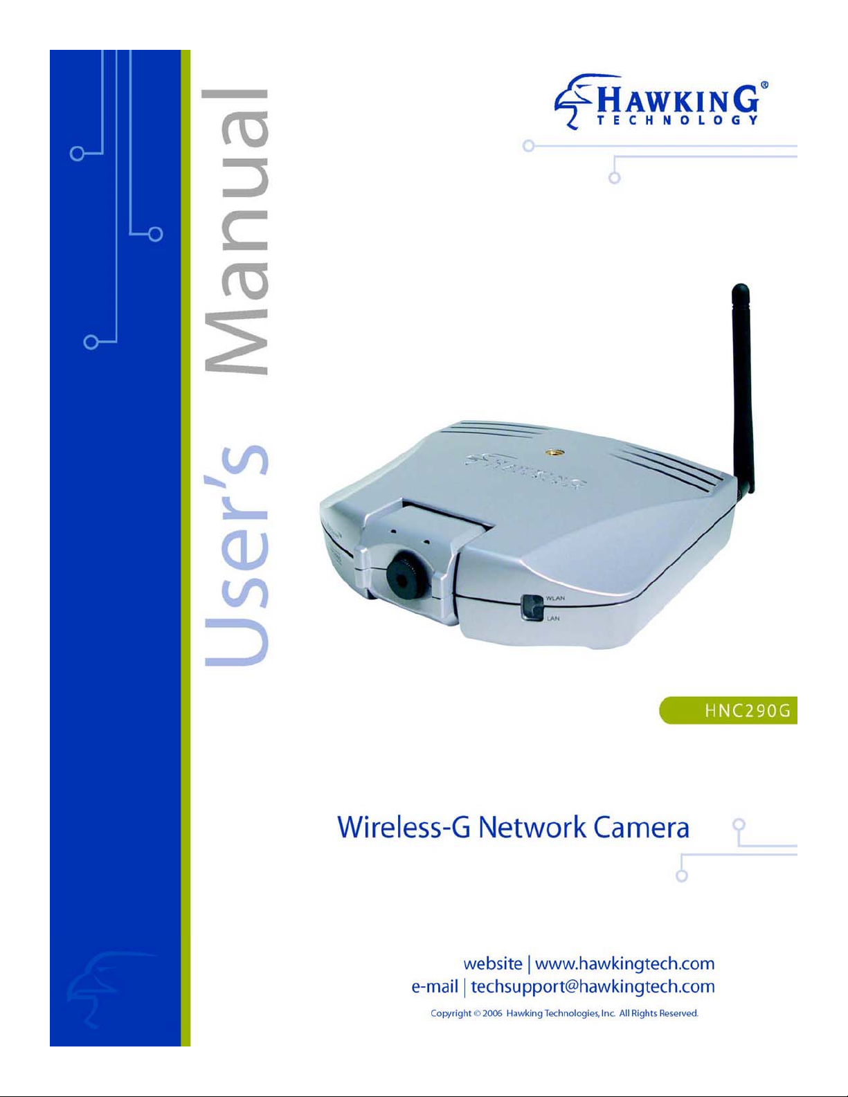
4.1 LEDs and Focusing
The camera head and its focus ring allow you to modify the aim and focus of the camera. To adjust the camera’s focus,
rotate the dark focus ring in either direction until the desired viewing area or object becomes sharp/clear.
There are four LEDs that indicate camera and network status:
y Power
The LED will be lit orange when the device is powered on and ready for access.
y Link
When the camera is monitoring, the LED will be lit green.
y WLAN
When the network camera is linked to a wireless LAN access point or a wireless station, the LED will be lit green.
The LED will flash when video is transmitted or received via the wireless network.
y LAN
When the network camera is linked to a wired network, the LED will be lit green. The LED will flash when video is
transmitted or received via the wired network.
LED: Power
Lens & Manual
Focus Ring
LED:
WLAN
LED:
LAN
LED: Link
8
Page 9
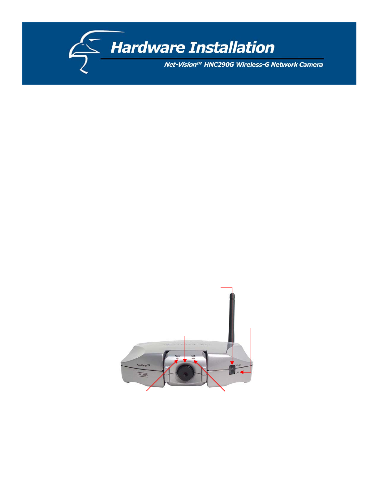
4.2 Camera Ports
p
The back panel of the network camera includes three ports and a Reset button.
y Antenna Connector
This is a standard Reverse-SMA connector. Any antenna with a Reverse-SMA connector can be connected to the
network camera.
y Power
The “Power” port is where you will connect the network camera’s power adapter.
y LAN
The LAN port is where you will connect the Ethernet network cable.
y Reset
1. If a problem occurs with the network camera, but you do not want to reset it to its original default settings, press
the reset button for less than two seconds (using a pen or pencil tip, or something similar) and the network
camera will re-boot itself and keep your original configurations.
2. If a problem persists, you experience more severe problems, or you forgot your password, press the reset button
for longer than five seconds and the network camera will reset itself to the original factory default settings
(warning: your configurations will be replaced by the factory default settings).
Power
ut
In
Antenna
Reset
Button
LAN
Port
9
Page 10
4.3 Installation Procedure
1. Unpack all of the contents from the network camera’s package and verify that all the items listed in the “Package
Contents” chapter have been included.
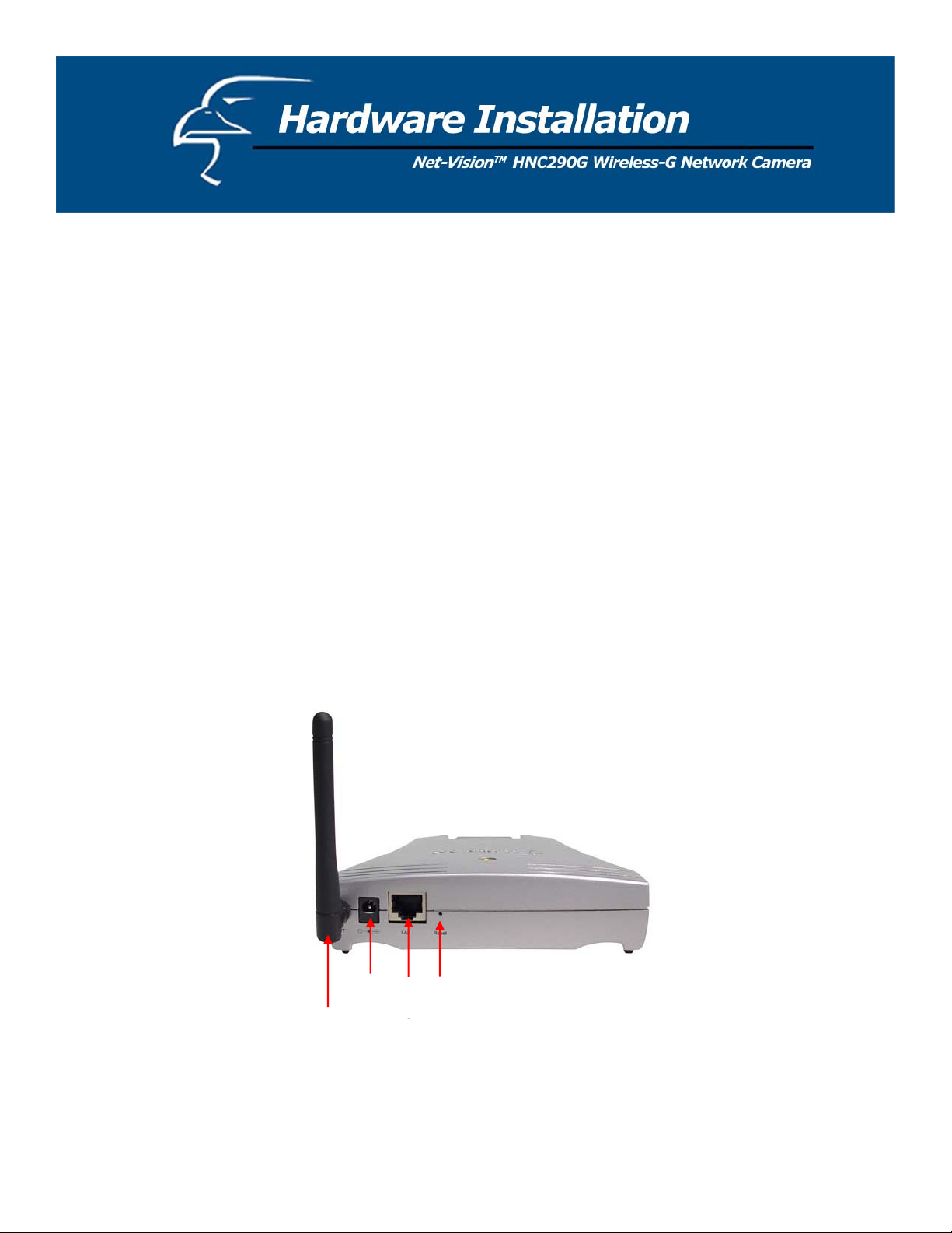
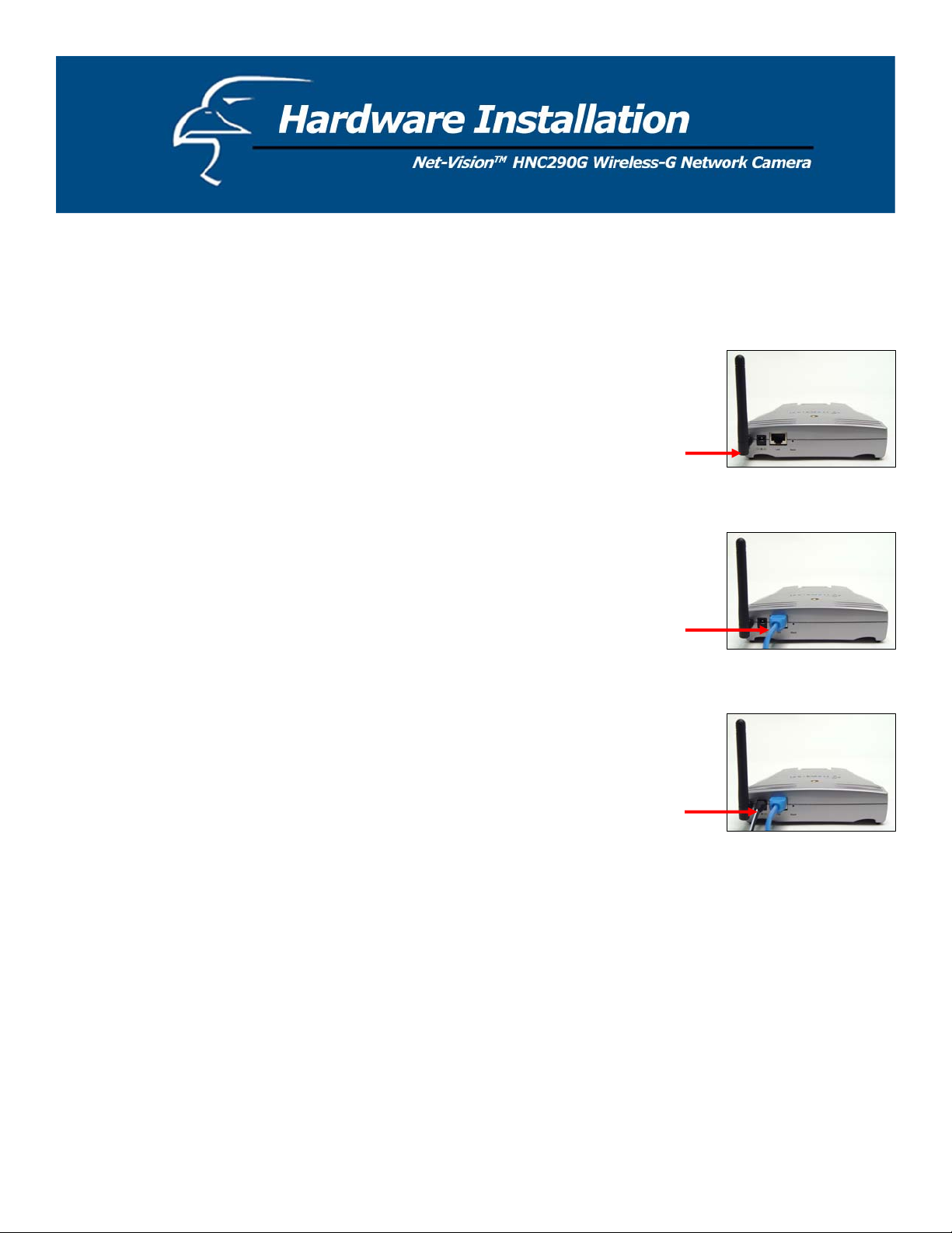
2. Locate the antenna connector on the left side of the camera’s rear panel. Screw the
base of the antenna (included with the HNC290G) into the antenna connector.
2
3. Locate the network cable connector (RJ-45 port) on the camera’s rear panel. Connect
an Ethernet cable to the port. Connect the other end of the cable to the network.
Please Note: For initial setup and configuration, you will need to use a wired
connection. After completing the setup and configuration, you can begin using your
network camera wirelessly.
3
4. Locate the power input connector on the camera’s rear panel, and attach the external
power supply. Then, plug the adapter into an available outlet. Please check to see
that the orange “Power” LED located next to the lens of the camera (front side) is lit
to ensure that the camera is powered on. (To ensure a network connection, please
check to see that the green “Link” LED is lit or flashing.)
4
Please Note: It is strongly recommended that you use the power adapter that was shipped with the network camera. Do
NOT use power adapters from any other source.
10
Page 11
Please follow the steps below to run the Install Wizard, which will guide you through the Administrator utility and
Camera Viewer installation processes. The following installation procedure described here is for Windows XP. The
installation procedures for Windows 98SE/Me/2000/Server 2003 are similar.
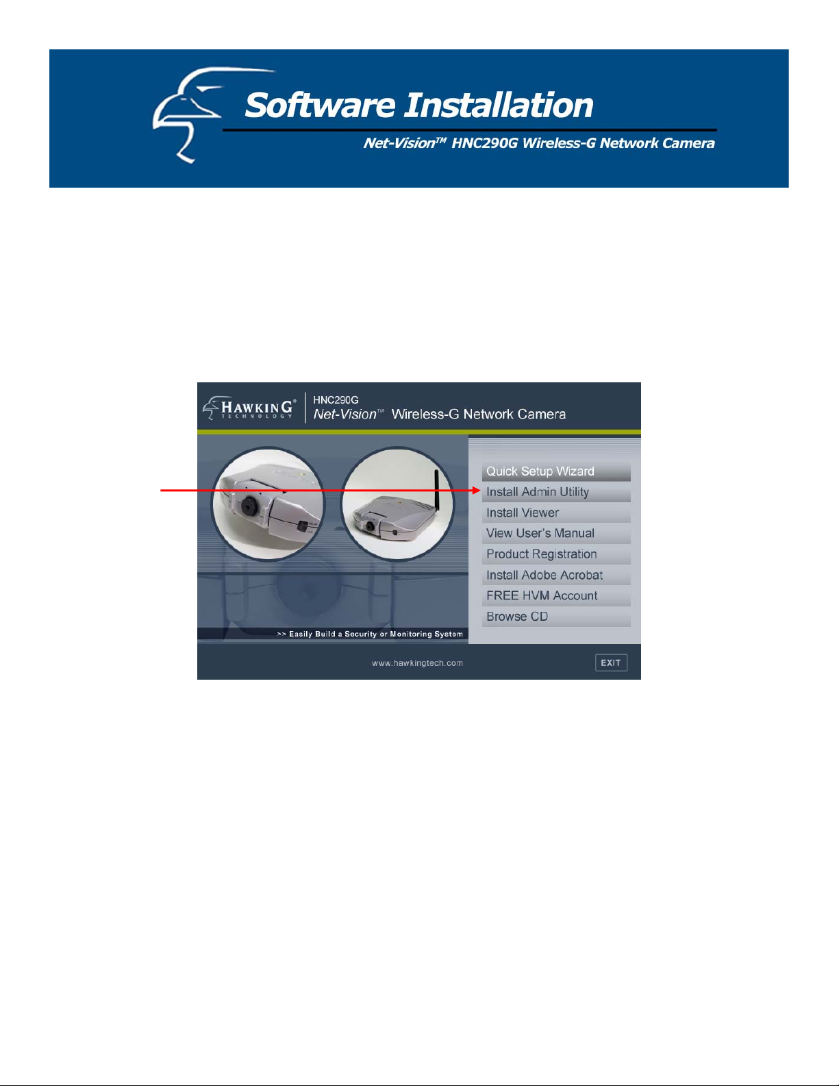
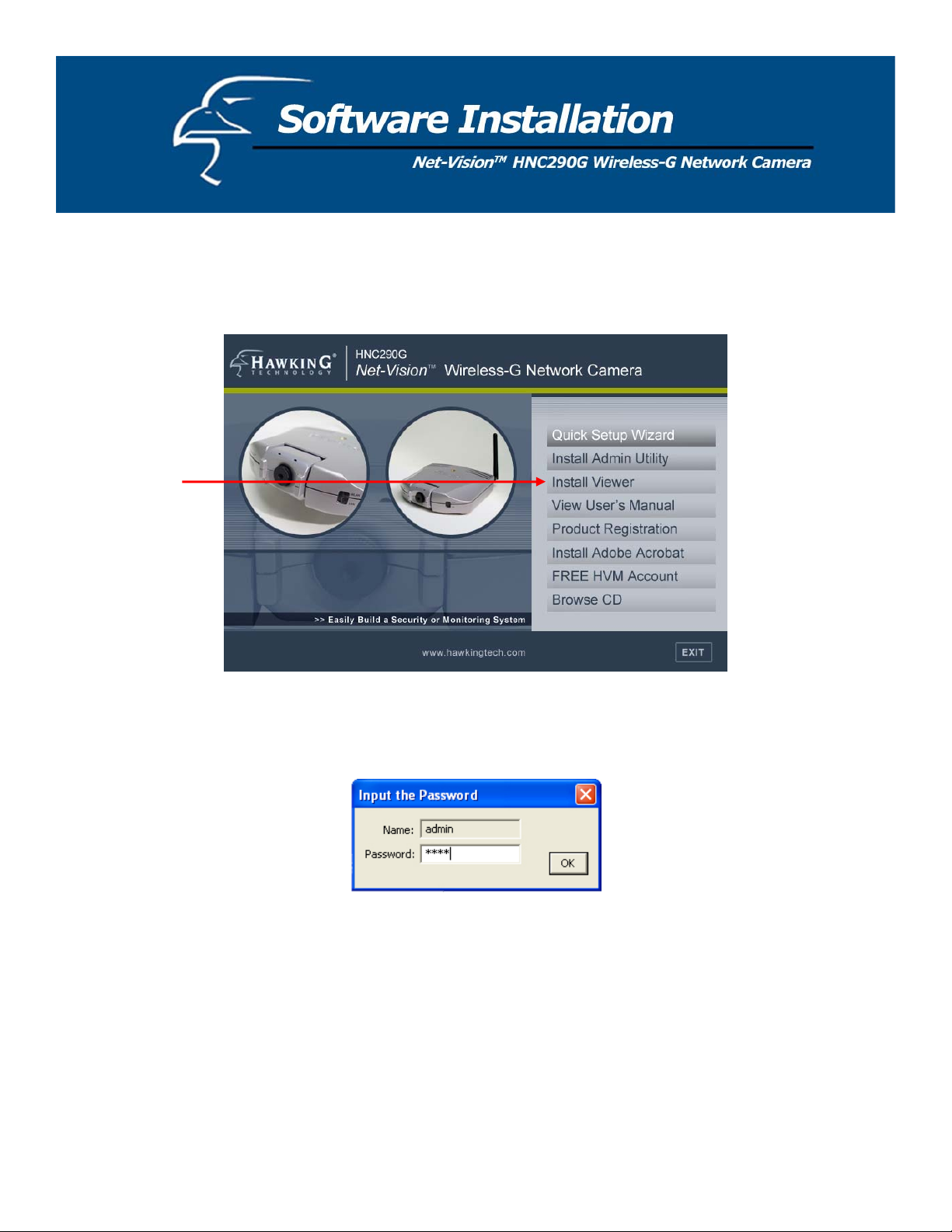
1. Insert the CD that was included in the network camera’s package into your CD-ROM drive. The “Autorun.exe”
program should execute automatically and the following window will appear. If the program does not execute
automatically, you can run the “Autorun.exe” program manually from the “Autorun” folder on the CD.
2. The window will display eight items on the right hand side. Please select the program you would like to install or
click “Exit” to install the program later. The following steps describe the installation process for the Admin Utility.
Click on “Install Admin Utility”. After you have installed the Admin Utility, you can install the Viewer utility in the
same manner by clicking on “Install Viewer”.
11
Page 12
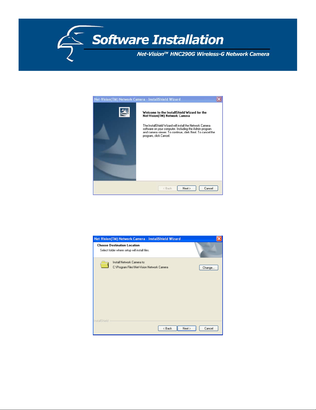
3. The InstallShield Wizard will begin the installation process. Click “Next” to continue with the installation.
4. If you wish to install the software program in an alternate location, click “Change”; otherwise, click “Next” to move
on to the next step.
12
Page 13
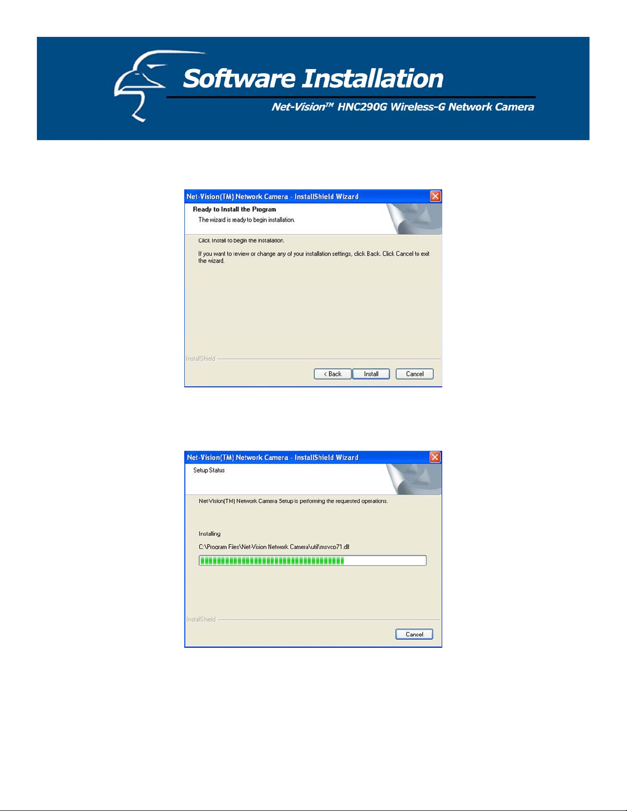
5. Click “Install” to begin installing the program.
6. The system will install the program automatically.
13
Page 14
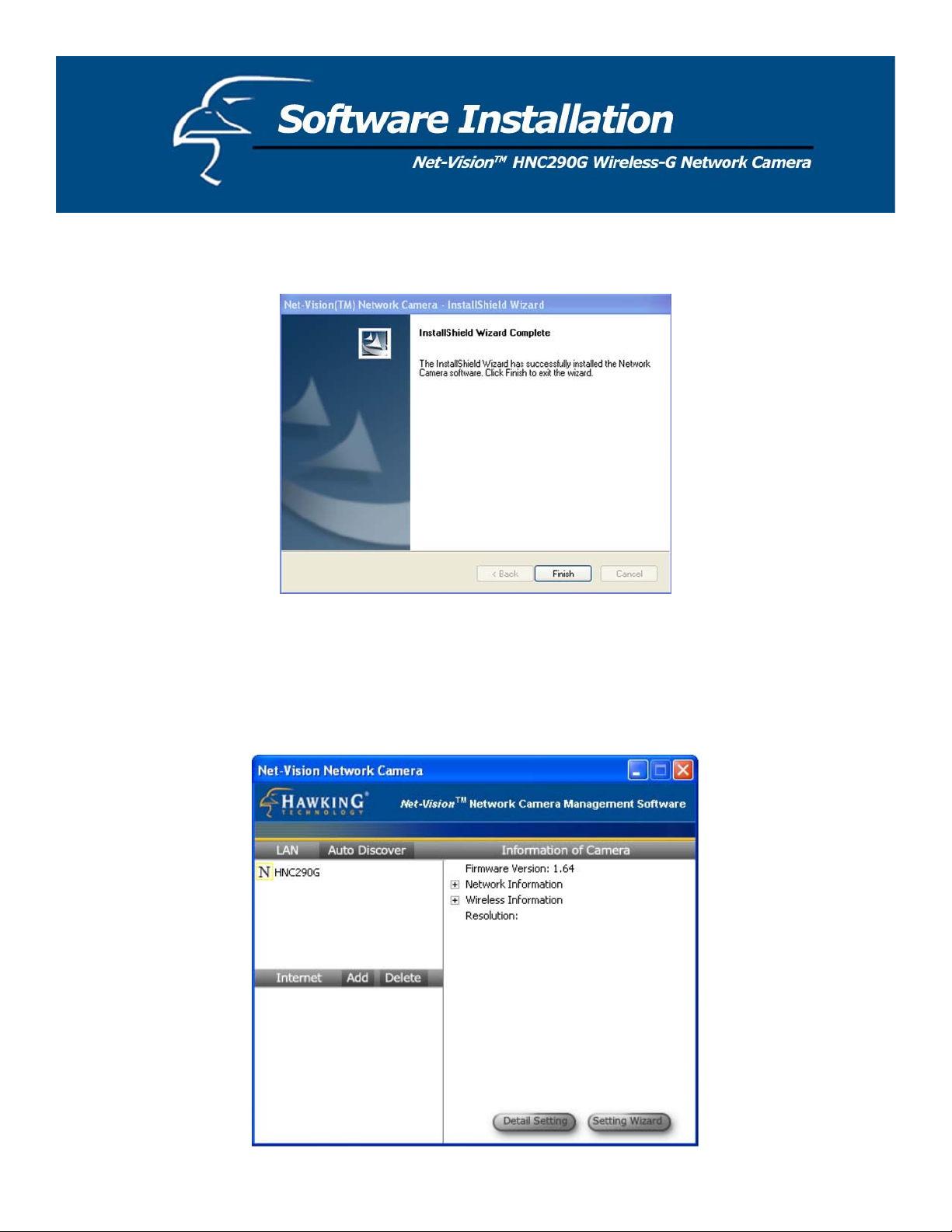
7. Click “Finish” to complete the software installation.
8. When the installation is completed, the system will auto run the “Administrator Utility”. On the first page, the
cameras that can be found on the network are listed on the left side of the window. Select the one you would like to
configure and click “Setting Wizard” to proceed.
14
Page 15
Please Note: To install the Camera Viewer utility, you can follow the same steps you used to install the Admin utility.
But this time, simply click on the “Install Viewer” option.
9. Please enter the default password of “1234”, and click “OK” to log in to the IP setup page.
15
Page 16
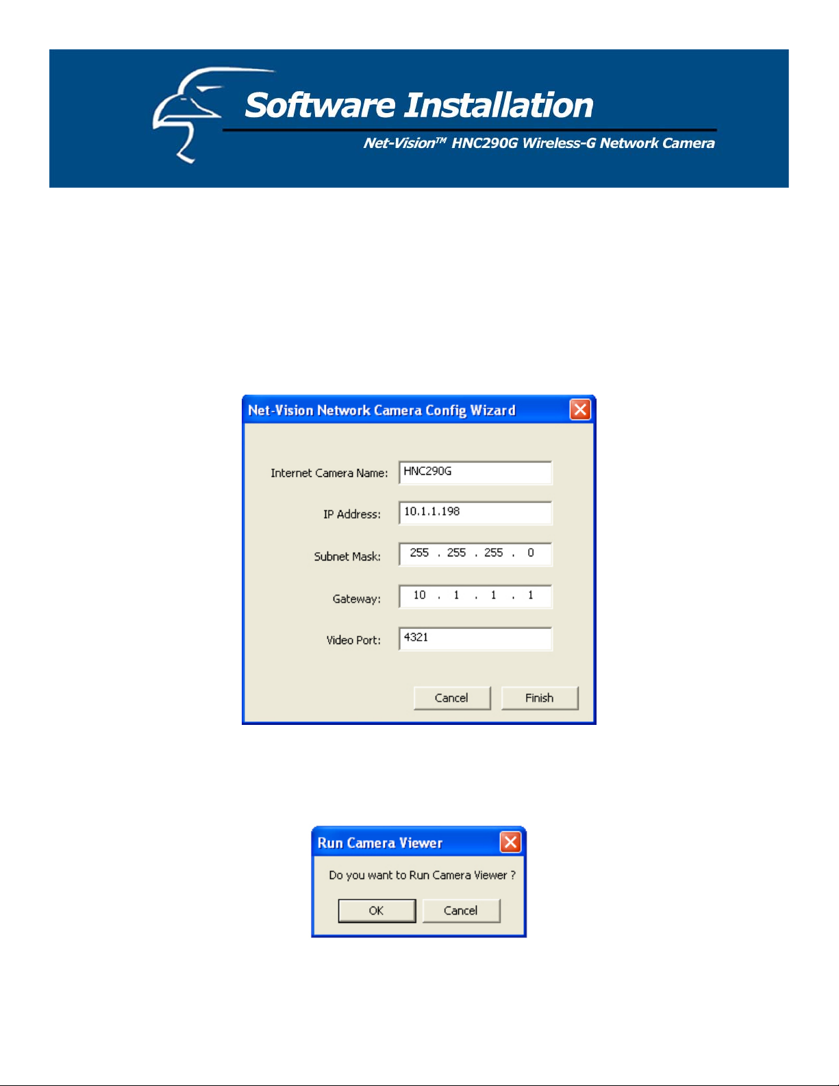
10. As an alternate method to the Quick Setup Wizard, you can set up the network camera using the Admin utility. The
network camera is connects and functions through the network (using the TCP/IP Protocol). Therefore, the camera’s
IP address settings must be consistent with your network settings, or you will be unable to access it. The wizard
program within the Admin utility will automatically detect the IP address status of your network and suggest a free IP
address for the Camera. You can either accept the suggested settings or manually enter the settings in the fields
provided. If you configure the settings manually, please note that the “Subnet Mask” must be the same for both the
camera and your PC. (If you would like to learn more about how to ensure that your network camera’s IP settings are
consistent with those of your network, you can refer to the section in the Quick Installation Guide titled “Example on
How to Set the IP Address Manually”.) Click “Finish” to apply the new settings.
11. This wizard will pop up a window that will ask you if you want to run the Camera Viewer and see the camera video
immediately. Select “OK” to run the Camera Viewer.
16
Page 17
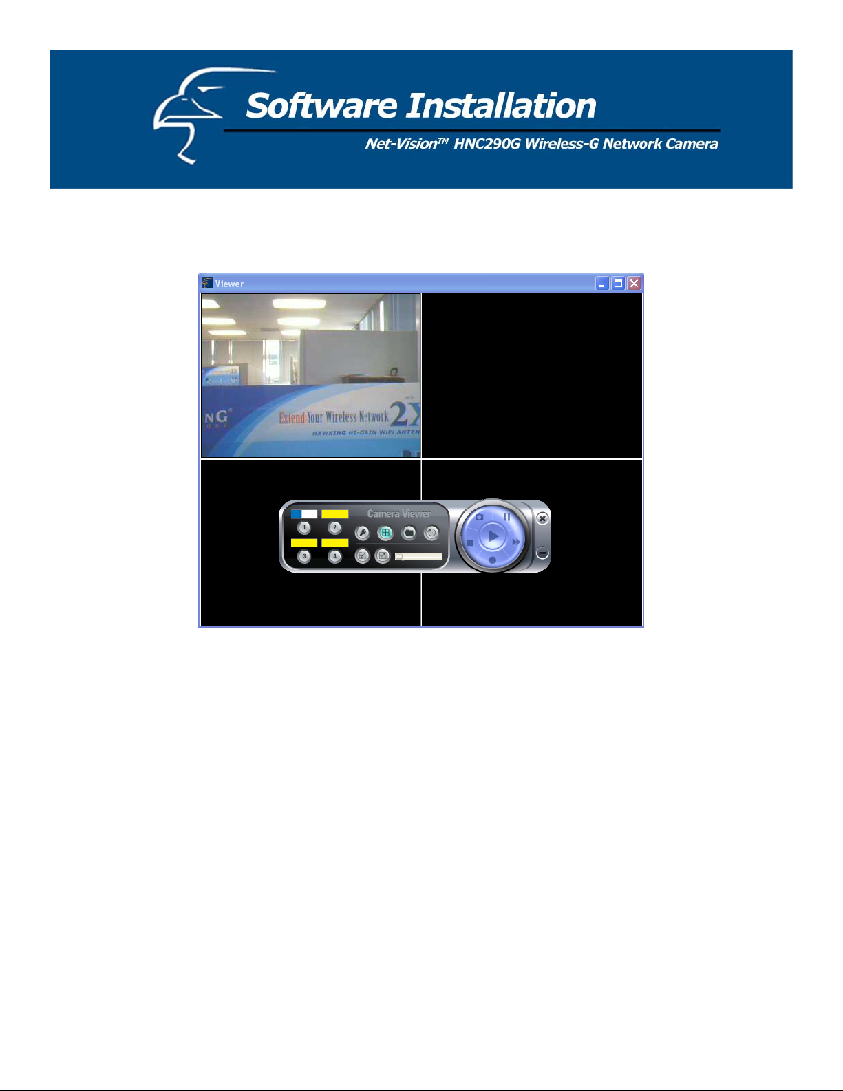
12. The Camera Viewer will show the video automatically. You can now view the camera video through the network
from this point on.
17
Page 18
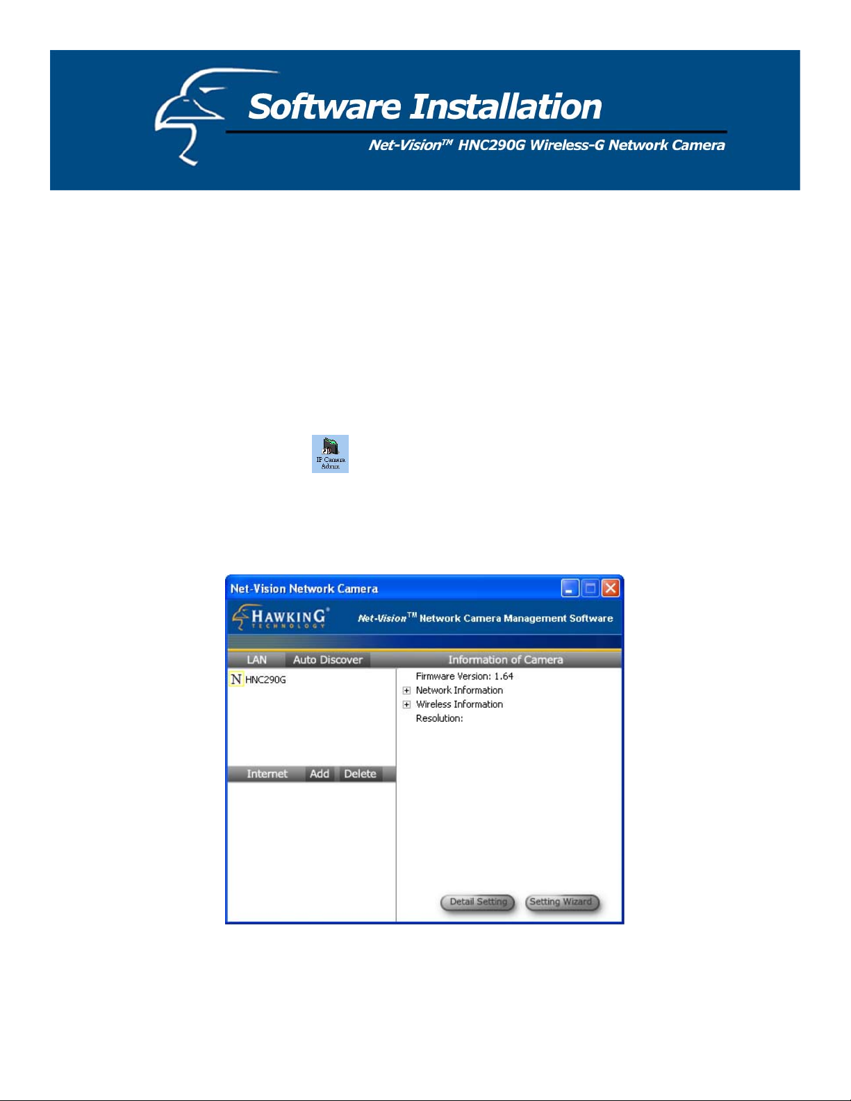
The Admin utility allows users to search for and set up the network cameras located within the Intranet or on the Internet.
From the utility, users can view all of the selected cameras’ information. It also provides a Setting Wizard, which easily
guides users through the process of installing network cameras on the network. (Remember that you can also install
network cameras on the network using the Quick Setup Wizard that is located on the CD.) Please remember that you can
only use the Admin utility that is included with this network camera with similar cameras that are available on your
network. A “similar” camera will have the same code of four letters at the beginning of its serial number. This code is
“HEMT” and can be found on either the right or left panel of the camera packaging, or on the label on the bottom of the
camera.
There are two ways to run the Admin utility:
1. Click “Start”, and then select “Programs\IP Camera\Admin Utility” to run the utility.
2. Click on the “IP Camera Admin” icon
to run the utility.
Once you have initialized the utility, it will search for all similar cameras available on your network. To configure more
detailed settings, please refer to the descriptions in the sections that follow.
18
Page 19
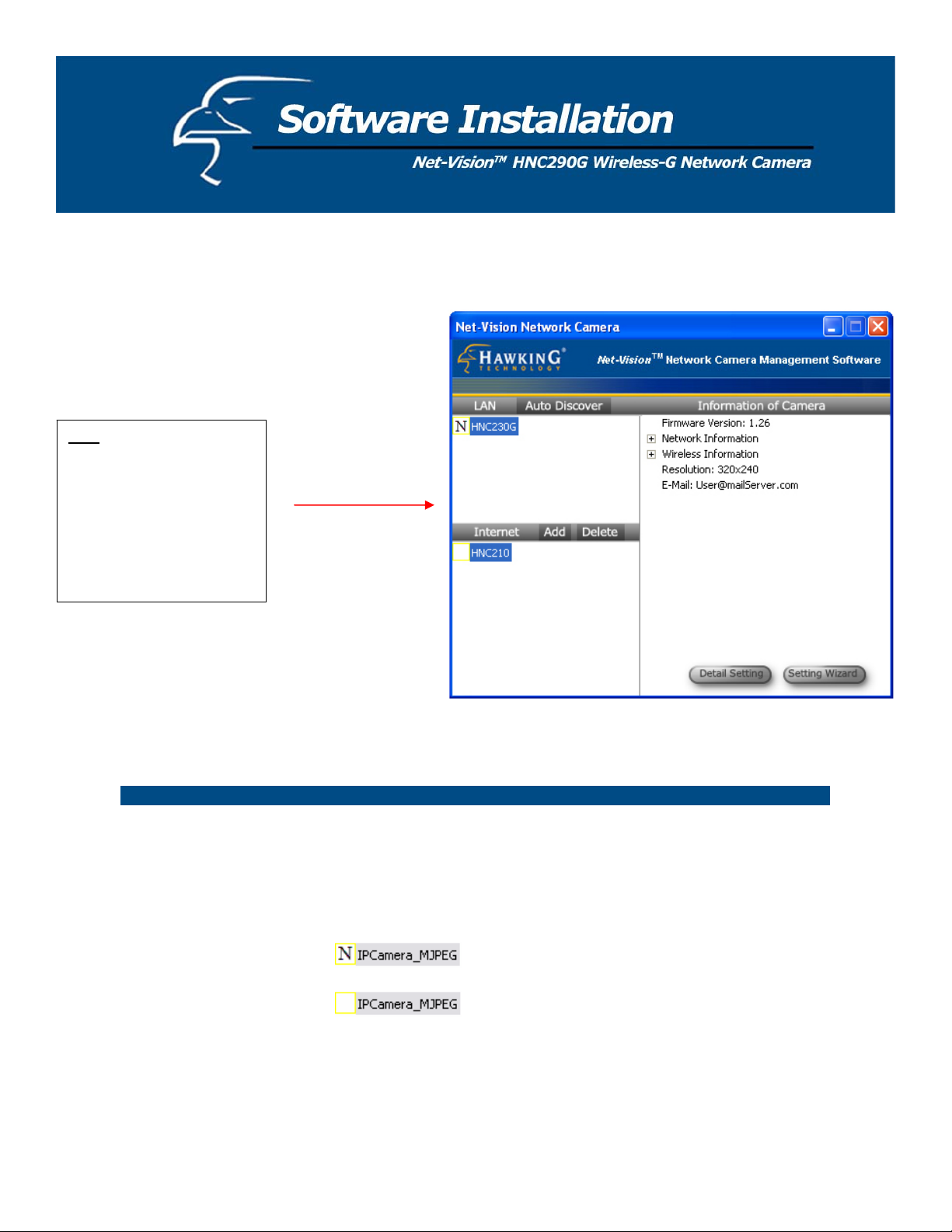
6.1 General Settings
Note: This figure shows older
camera models: the
HNC230G and HNC210.
This figure is meant for
illustrative purposes only and
the setup procedures for the
HNC290G will remain
exactly the same.
LAN
Auto Discover Click this button to have the Admin utility search for and automatically
discover available cameras within the network.
Camera List The camera list displays the camera name and setup status for each
camera.
This means the camera still has its default settings.
This means the camera has been configured.
19
Page 20
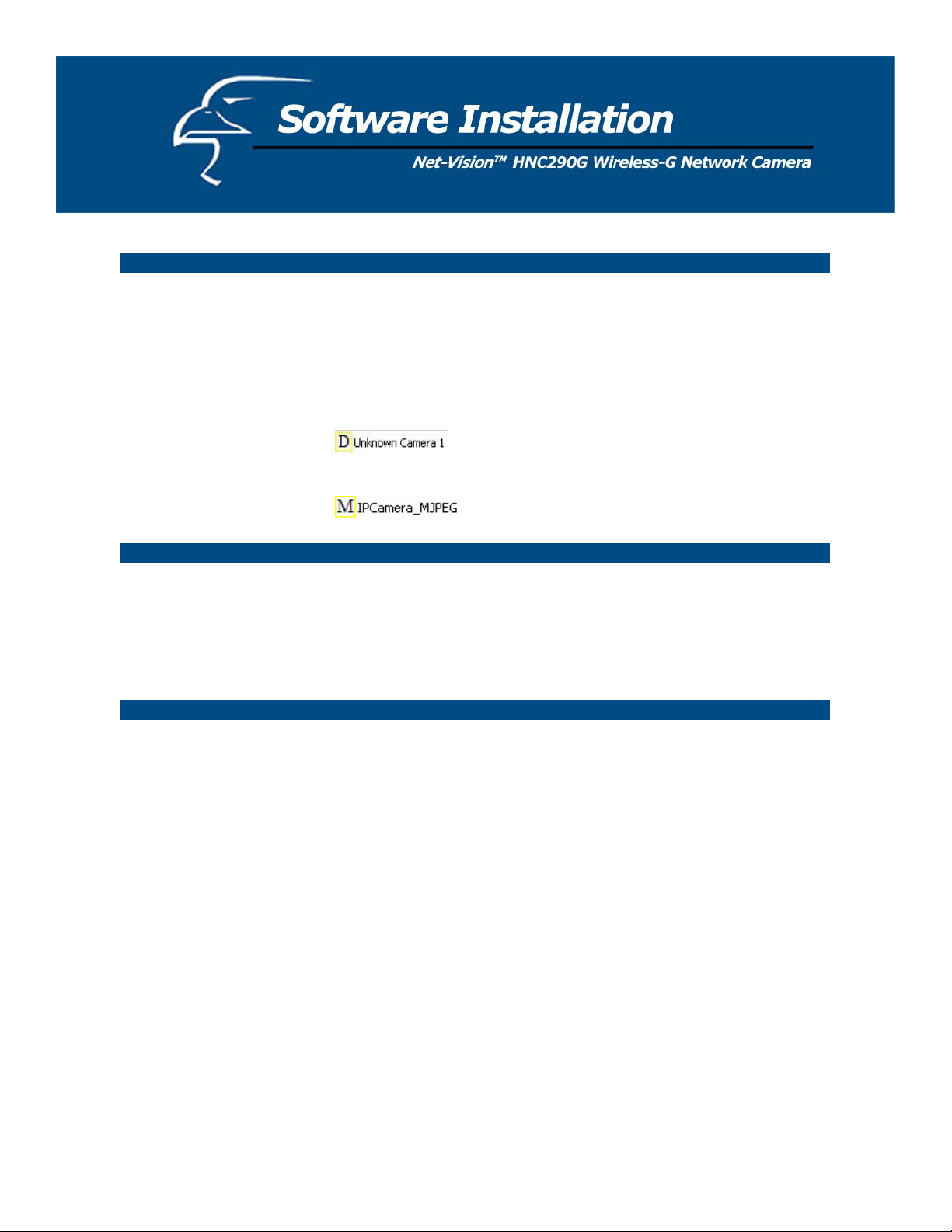
Internet
Add Click “Add” and a window will appear for you to enter the IP Address
of the camera that is available on the Internet.
Delete Click “Delete” to delete the camera from the list.
Camera List This list displays the camera name and its connection status.
This means the camera is disconnected or not
available on the Internet.
This means that the camera is connected.
Information of Camera
Camera Information This portion of the window displays some of the selected camera’s
important information. The information includes: Firmware Version,
Network Information (click to expand and view: IP Address, UPnP
Setting, DDNS Setting, and more), Wireless Settings (click to expand),
Resolution and E-mail settings.
Camera Setting
Detail Setting Click “Detail Setting” to configure additional settings for the selected
camera, such as IP address, Resolution, password, firmware upgrade,
etc.
Setting Wizard Click on “Setting Wizard” to configure the necessary IP settings for the
camera.
20
Page 21
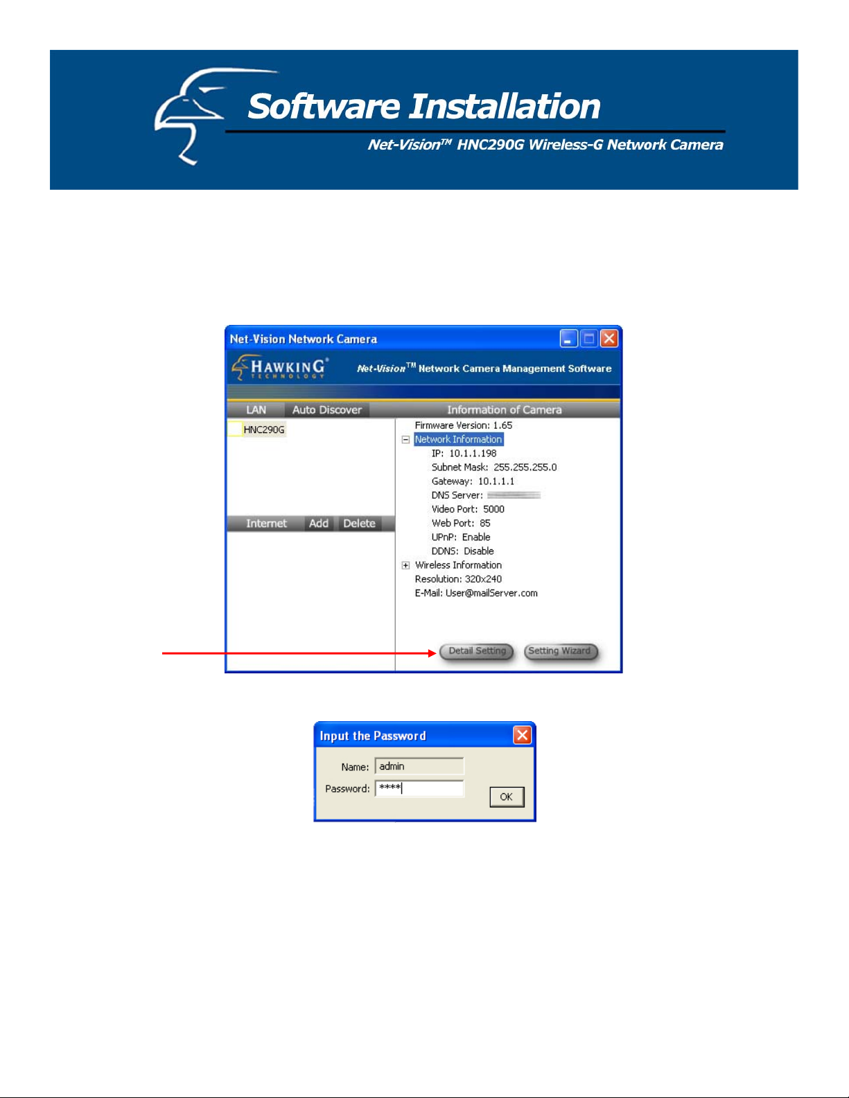
6.2 Detailed Settings
When you click on the “Detail Setting” button, a window will pop up for you to enter the “Admin Name” and
“Password”. The default values are as follows: Name: “Admin”, Password: “1234”. If you have already changed the
password (in the Quick Setup Wizard, for example), then enter the one in the “Password” field.
If the name and password you enter are correct, you can begin setting up the camera.
21
Page 22
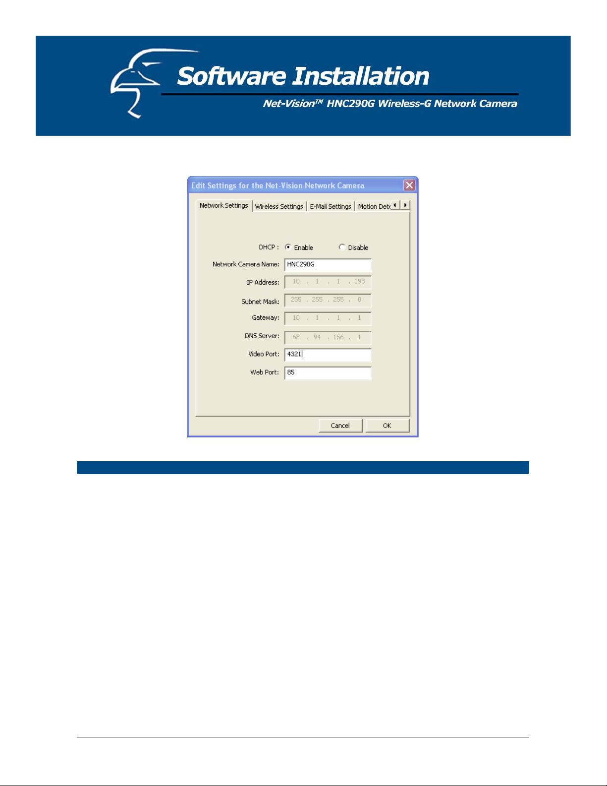
6.2.1 Network Setting
Network Settings
Network Camera Name The default camera name is “HNC290G”. It is recommended that you
give the camera a name that will be easy to remember, such as by
location, application, etc.
IP Address Enter an unused IP Address that is consistent with and inside the IP
address range used on your LAN. If the IP Address range of your LAN
is from 192.168.2.1 to 192.168.2.254, an example of an unused IP
address within this range might be: 192.168.2.250.
Subnet Mask The Subnet Mask field must match the subnet setting on your LAN. For
example: 255.255.255.0.
Gateway The Gateway (usually the router on your LAN) is used to forward frames
to destinations in a different subnet on the Internet. The Gateway setting
must be the same as the gateway used by the PCs on your LAN.
DNS Server The DNS Server (Domain Name Server) translates names to IP
addresses. The DNS Server setting is the same as the setting for the
PCs on your LAN.
22
Page 23

Network Setting
Video Port The Video Port is used to transmit or receive the streaming video over
the network. The default port setting is “5000”. If you want to view
the video from the camera, the port setting must be correct.
Web Port This camera supports web connection. The default web port is 80.
Since the web server may use port 80, you can use a different port for
the camera. If you change the web port from 80 to 85, for example,
you must type http://192.168.2.3:85 in the web address bar to connect
to the camera through the web browser.
PLEASE NOTE: If you have DHCP enabled on your router, the LAN IP address of your network camera may
periodically change, for example when you reboot the camera, power off and power on your camera, etc. To avoid this,
you can set the LAN IP address of the camera as static by disabling the “DHCP Function” (which is enabled by default) in
the “Network Settings” page of the camera’s web UI, once you have finished installing/setting up the camera. Again,
when you initially install the camera, either the Setup Wizard automatically assigns it an IP address or you manually
assign one in the Setup Wizard. Disabling the DHCP function will make this IP Address static. After this, the camera’s
IP address will not change unless you perform a factory default reset on it.
23
Page 24
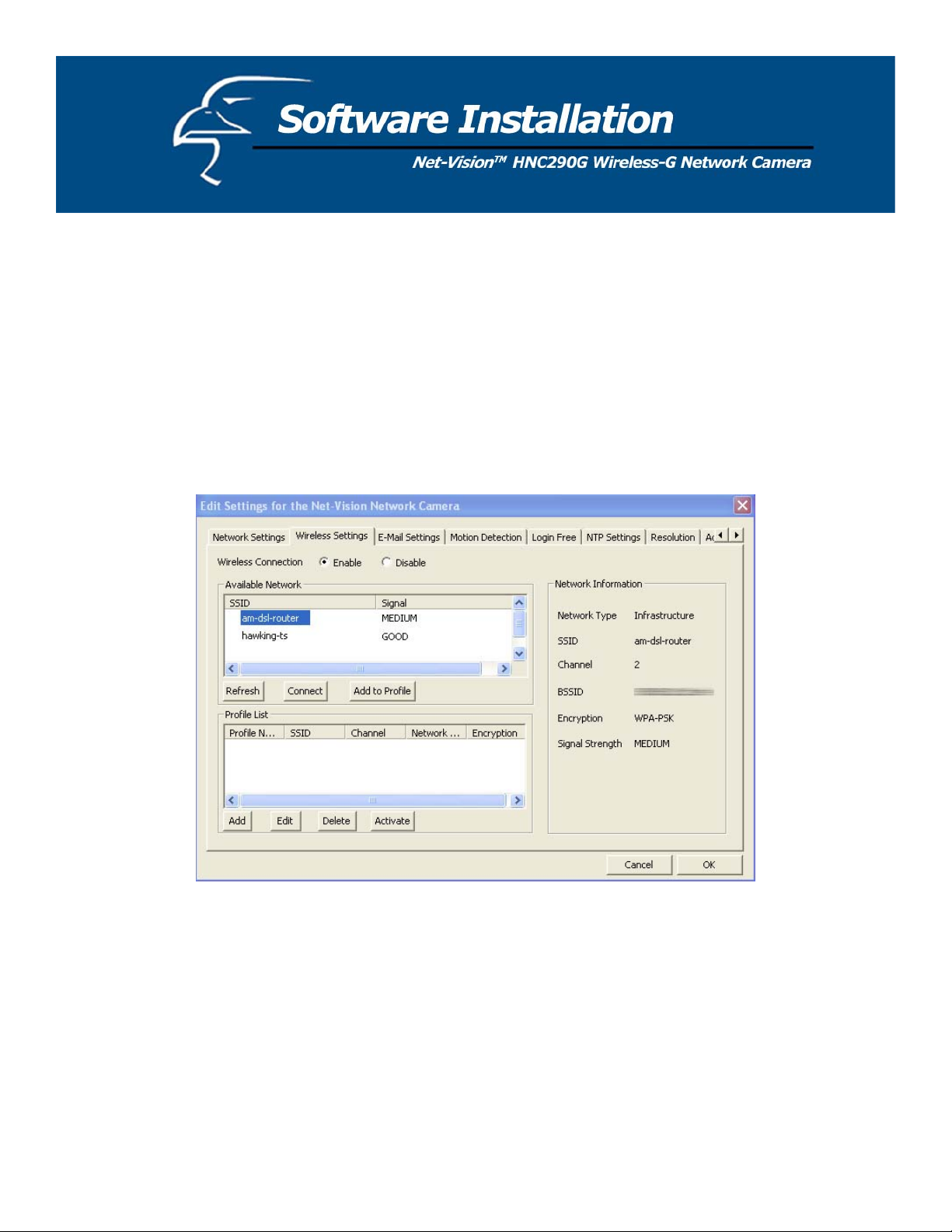
6.2.2 Wireless Settings
If you want to use the network camera via your wireless LAN, please set it up using a wired Ethernet connection first and
make sure your wireless LAN settings are correct. After configuring the wireless LAN settings, you can unplug the
Ethernet cable and begin using the camera via the wireless LAN. (Please Note: If the camera does not directly connect to
the wireless LAN when you unplug the Ethernet cable [in other words, if you do not immediately begin receiving video],
you may need to perform a soft reset on the camera. You can do this simply by unplugging and re-plugging the camera’s
power adapter.)
If the wireless configuration does not work the first time, please plug the Ethernet cable in again, and configure the
camera via the wired Ethernet connection until the wireless LAN settings are correct.
24
Page 25

Wireless Setting
Wireless Setting Enable or disable the network camera’s wireless function. By default,
the function is disabled.
Available Network
Available Network This list shows all available wireless networks within your network
camera’s accessible range. It also displays the important information
from these networks, including the SSID and Signal Strength. If you
want to connect to any of the networks on the list, double-click the item
on the list or select the item and click “Connect”, and the camera will
automatically connect to the selected network.
Refresh Button Click the “Refresh” button to collect new information on all of the
nearby, accessible wireless networks.
Connect Button Click the “Connect” button to connect to the selected network.
Add to Profile Button Add the selected network to the Profile List and save it on your PC.
25
Page 26

Profile List
Profile List The “Profile List” allows you to manage the networks you connect to
frequently. The profile list displays all the profiles and their
corresponding settings, including Profile Name, SSID, Channel, etc. If
you want to connect to any of the profiles on the list, double-click the
profile or select the profile and click “Activate”. The network camera
will then automatically connect to the selected profile.
Add/Delete/Edit Button Click these buttons to add/delete/edit the selected profiles.
Activate Button Click “Activate” to connect to the selected profile. When a profile is
activated, the card will initially be connected to the profile.
Configure the Profile
Profile Name Allows you to define a recognizable profile name so that you can
identify the different profiled networks.
SSID The SSID (up to 32 printable ASCII characters) is the unique name
used to identify a wireless LAN (WLAN). The ID prevents the
unintentional merging of two co-located WLANs.
You may specify an SSID for the card and then only the device with the
same SSID can interconnect to the card. If you want to add one of the
networks nearby to the profile list, pull down the menu, and all of the
networks nearby will be listed. Thus, you can add one of them to the
profile list.
Channel This setting is only available for Ad Hoc mode. Select the number of
the radio channel used for networking. The channel setting should be
the same as the channel of the network you are connecting to.
Network Type Infrastructure: This operation mode requires the presence of a Wireless
LAN Access Point or Router. All communication occurs via the
Access Point or Router.
Ad-Hoc: Select this mode if you want to connect to another wireless
station in the Wireless LAN network without an Access Point or
Router. Select this option if you want the network camera to operate in
peer-to-peer mode.
26
Page 27

Configure the Profile
Authentication Type
Allows you to select between “None”, “Open System”, “Shared Key”,
and “WPA-PSK”.
Encryption Type
Select the type of encryption that your wireless network is using. If
you are unsure about the type of encryption your wireless network is
using, you can refer to your router’s or gateway’s settings for details.
WPA Pre-Shared Key
If your wireless network uses WPA encryption, type in your WPA key
in this field.
Key Length
You may select either the 64-bit or 128-bit option to encrypt
transmitted data. A larger key length will provide a higher level of
security, but the throughput will be lower.
Key Format Hexadecimal: You can only use the following characters to set the
WEP key in this format: “A-F“, “a-f“ and “0-9“.
ASCII: Numerical values, characters or signs are acceptable for this
WEP key format. This is usually the easier option for most users.
Default Key Select one of the keys (1 - 4) as the encryption key.
Key1 - Key4 WEP keys are used to encrypt data transmitted over the wireless
network.
Fill in the text boxes by following rules below.
64-bit: Input a 10-character Hex key (using “A-F”, “a-f” and “0-9”) or
a 5-character ASCII key (using “a-z” and “0-9”). For example:
“0123456aef” (Hex) or “test1” (ASCII).
128-bit: Input a 26-character Hex key (using “A-F”, “a-f” and “0-9”) or
a 13-character ASCII key (using “a-z” and “0-9”). For example:
“01234567890123456789abcdef” (Hex) or “administrator” (ASCII).
Network Information
Network Information List This list shows detailed network information for the selected network in
the Available Network list. The information includes: Network Type,
SSID, Channel, BSSID, Encryption Setting and Signal Strength.
BSSID refers to the MAC Addresses of the wireless devices.
27
Page 28

6.2.3 Email Settings
E-Mail Setting
Recipient Email Address This camera supports the “Snapshot” function. You can snapshot a still
image and send the picture via E-Mail. Enter the E-Mail Account
where you would like to receive the picture.
SMTP Server
Sender E-mail Address
SMTP Authentication
PLEASE NOTE: Some SMTP servers require authentication via an account name (or user name) and password. You can
check this in Microsoft Outlook, for example, by clicking on the “Tools” tab on the top of your Outlook page. Once in the
“Tools” page, click on “Accounts”, then “Properties”, and then finally “Servers”.
Enter the SMTP Server from which you would like to send the E-Mails.
Type the email address of the sender in this field.
If your SMTP server requires authentication, please click on the
“Enable” radio button. Then type in the appropriate “Username” and
“Password”. (Please note that this information applies to the sender’s
SMTP server.) If you are unsure of whether or not your SMTP server
requires authentication, please check your email account settings.
28
Page 29
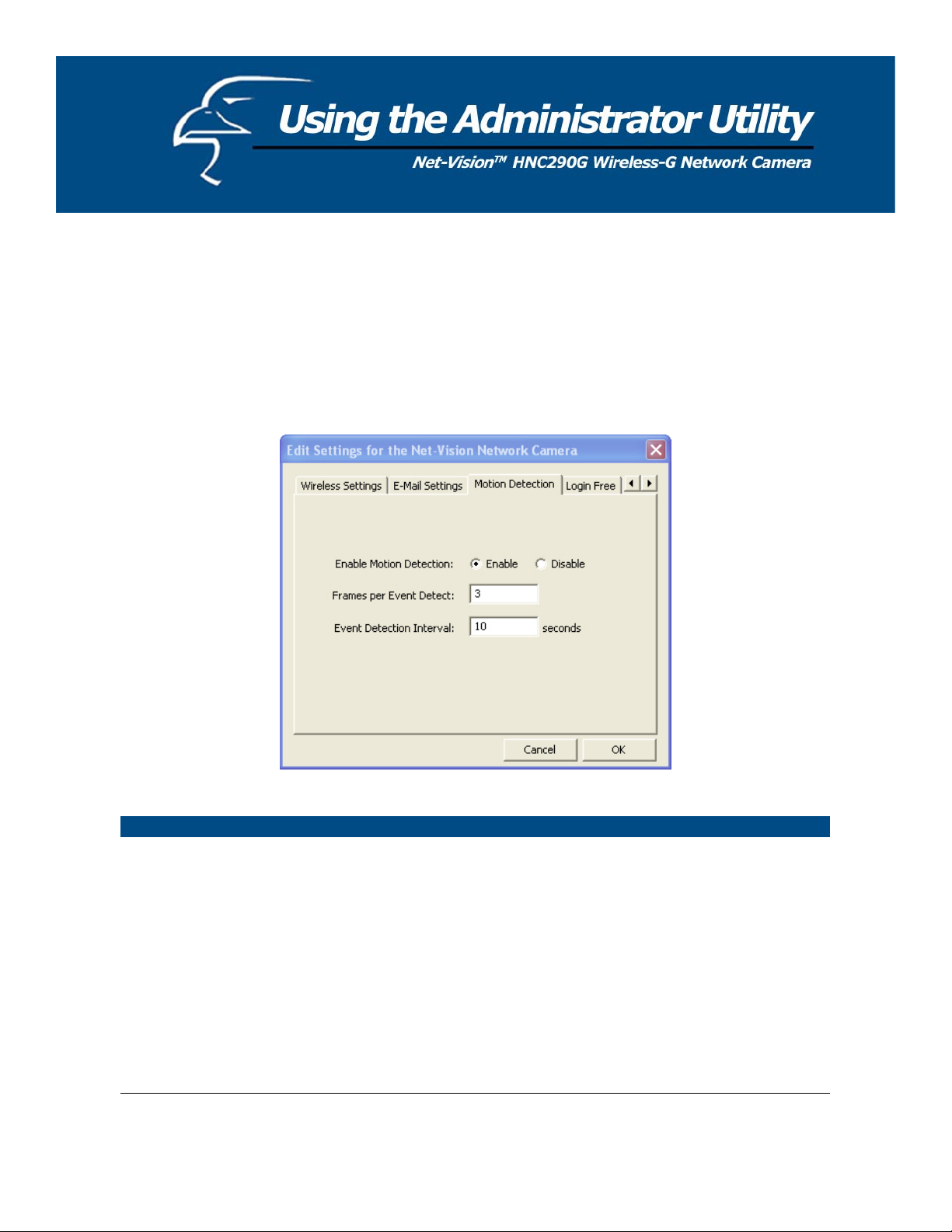
6.2.4 Motion Detection
The HNC290G features built-in motion detection with snapshot emailing. In order to utilize this feature, you will have to
enable it either in the “Network Settings” section of the camera’s web UI, or in the “Motion Detection” section of the
Administrator Utility, as shown in the figure below. Once enabled, the system will email still image snapshots to the
person or party specified in the “Recipient Email Address” field, as detailed in Section 6.2.3 Email Settings from the
previous page in this user’s manual. The user can define the number of snapshots to be emailed for each detected event,
as well as the frequency with which he/she wants events to be detected. Please see the instructions below.
Motion Detection
Enable Motion Detection Motion detection is disabled by default. Click on “Enable” to begin
using the motion detection function.
Frames per Detected
Event
Event Detection Interval
In this field, the user can select the number of still-image snapshots
he/she would like to be emailed per instance of detected motion. The
field is set at “3” by default.
In this field, the user can select the interval of time, in seconds, he/she
would like between consecutive events for motion detection. The field
is set at “10 seconds” by default. Please note that this camera does not
have the capability to detect motion continuously.
29
Page 30
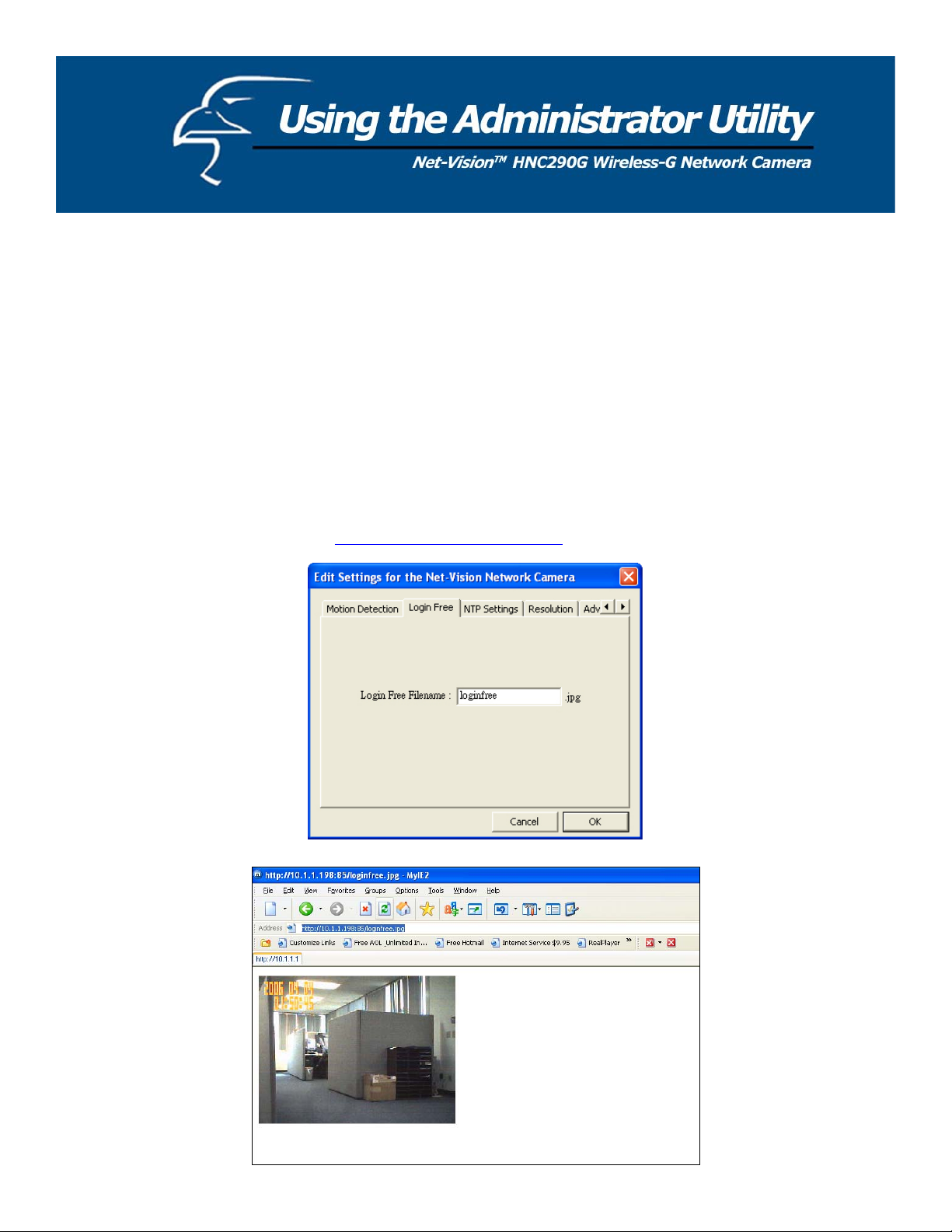
6.25 Login Free
The Login Free feature allows the user to isolate the video frame on its own page. Please note that this page will only
show a still image of the video frame. The user can click on the web browser’s “Refresh” button to update the image.
This can be useful when trying to access quick snapshots from the HNC290G from a cell phone, or when establishing a
free Hosted Video Management account (included with the purchase of this camera). In order to utilize this feature, you
will have to:
1. Type in the desired extension in the “Login Free Filename” field in the “Network Settings” section of the
camera’s web UI, or in the “Login Free” section of the Administrator Utility, as shown in the figure below. If you
do not wish to change the extension, the default extension is “loginfree.jpg”.
2. Type in the camera’s IP address in the “Address” bar of your web browser, followed by a forward slash and the
extension. In the example shown below, the camera’s local IP address is 10.1.1.198. Therefore, to access the
Login Free page, the user would enter the following into the address field: 10.1.1.198/loginfree.jpg. If you have
changed the camera’s web port, as has been done in the example below (web port: 85), the user would enter the
following into the address field: http://10.1.1.198:85/loginfree.jpg
.
30
Page 31
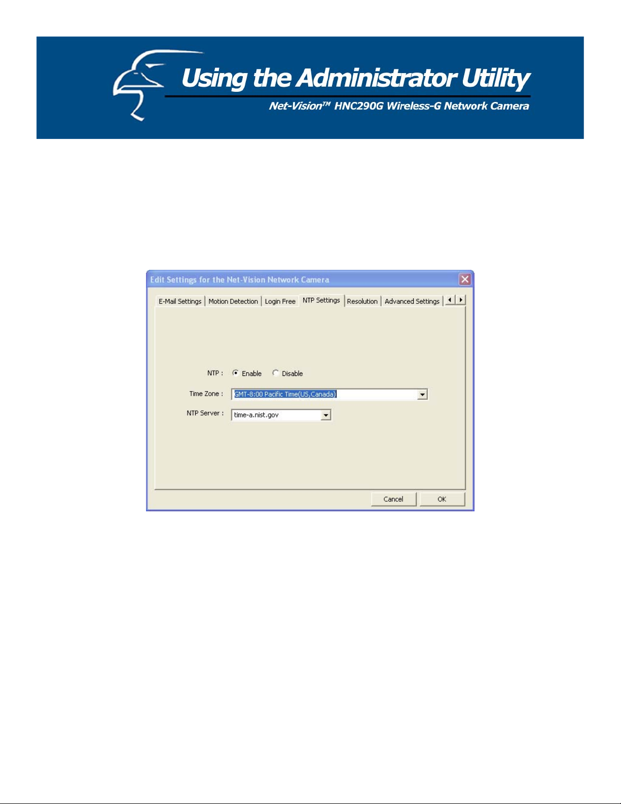
6.2.6 NTP Settings
The user can enable the NTP (Network Time Protocol) function by clicking on the “Enable” radio button. By activating
this function, you can sync the camera’s clock with one of the time servers provided in the “NTP Server” scroll-down
menu. Select the time zone from the “Time Zone” scroll-down menu, and then select the time server in the “NTP Server”
scroll-down menu.
31
Page 32
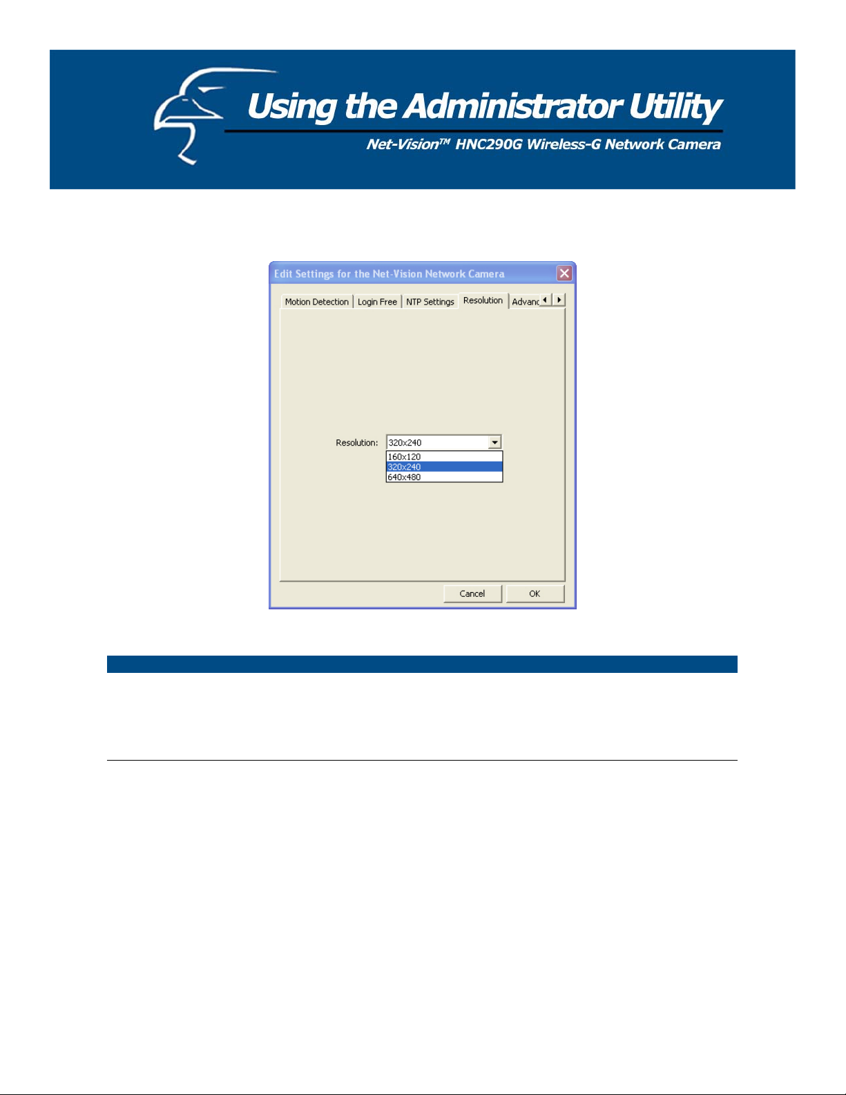
6.2.7 Resolution
Resolution
Resolution Select the desired video resolution format. Keep in mind that larger
resolution requires more bandwidth. 640 x 480 is “VGA” format. 320
x 240 is “CIF” format. 160 x 120 is “QCIF” format.
32
Page 33

6.2.8 Advanced Settings
Advanced Setting
UPnP
What is DDNS?
Enable/Disable Please use the camera’s web UI (see pg. 59 of this user’s manual) or the Quick
Provider The DDNS service for the HNC290G is provided by TZO.com.
Domain Name
Account Please use the camera’s web UI (see pg. 59 of this user’s manual) or the Quick
Password Please use the camera’s web UI (see pg. 59 of this user’s manual) or the Quick
When the UPnP function is enabled, the camera can be detected by a UPnP
compliant system such as Windows XP. The camera will be displayed in
Network Neighborhood, within Windows XP, so you can click on the camera
directly to view the video through the web browser.
DDNS is an acronym for “Dynamic Domain Name Server”. Many Internet
connections use a "Dynamic IP address", where the Internet IP address is allocated
dynamically whenever the Internet connection is established. This means that the
Internet IP address can change periodically. An Internet user would need to know
his/her Internet IP Address every time he/she wanted to connect to the camera
remotely over the Internet (i.e. from outside his/her LAN). DDNS is designed to
solve this problem, by allowing users to connect to their LANs using domain
names, rather than IP addresses. The domain name never changes. For instance,
“yahoo.com” is an example of a domain name that corresponds to an Internet IP
address. Rather than accessing this site by typing its Internet IP address in the web
address bar, users simply type: http://www.yahoo.com
. Similarly, you can use a
DDNS service to assign a domain name for your camera.
Setup Wizard (see pg. 21 of the Quick Installation Guide for instructions) to
set up the DDNS service.
Please use the camera’s web UI (see pg. 59 of this user’s manual) or the Quick
Setup Wizard (see pg. 21 of the Quick Installation Guide for instructions) to
set up the DDNS service.
Setup Wizard (see pg. 21 of the Quick Installation Guide for instructions) to
set up the DDNS service.
Setup Wizard (see pg. 21 of the Quick Installation Guide for instructions) to
set up the DDNS service.
33
Page 34
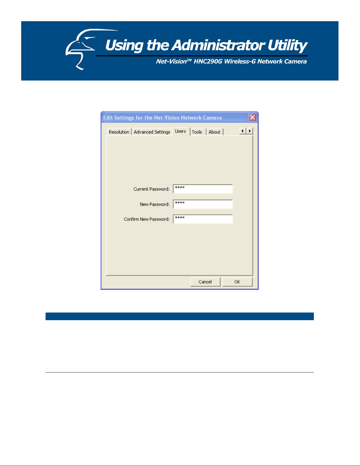
6.2.9 Users
Password
Current Password Enter the camera’s current password.
New Password Enter the new password you want to use for the camera.
Confirm New Password Retype the new password to confirm the setting.
34
Page 35

6.2.10 Tools
Tools
Firmware Version Displays the current version of the firmware.
Firmware Update Users cannot use the Admin utility to upgrade the firmware in this
version of the utility. Please upgrade the firmware via the web user
interface.
Reset to Default
If you want to reset the camera to its default settings, click this button.
The default settings of the camera are as follows:
Camera Name: “WIPCamera_MJPEG”
IP Address: “192.168.2.3”
Subnet Mask: 255.255.255.0
Administrator Name: “Admin”
Password: “1234”
Video Port: “5000”
Web Port: “80”
LED Light Off
Users can click on this button to turn off the camera’s LED lights. This
may help to make the camera less noticeable or to give it the
impression that it is not in use when, in fact, it is.
35
Page 36

6.2.11 About
About
Administrator Utility Version Displays the current version of the Administrator Utility.
36
Page 37

6.3 Setting Wizard
When you click the “Setting Wizard”, a screen will pop up for you to enter the “Administrator Name” and “Password”.
The default value is as follows.
Name: “Admin”
Password: “1234”
If the name and password you enter are correct, you can start to setup the camera.
37
Page 38

Setting Wizard
Internet Camera Name The default camera name is “HNC230G”. It is recommended that you
enter a name for the camera that is easy to remember.
IP Address The wizard will automatically set an available IP Address for the
camera. For example, if the IP address scheme for your network is
192.168.2.x, the wizard will search an unused IP Address between
192.168.2.0 and 192.168.2.250, and assign the camera an available IP
Address.
You may enter another IP Address to change the setting.
Subnet Mask The wizard will auto search the network’s Subnet Mask setting and set
the camera to the same Subnet Mask.
You may enter another Subnet Mask to change the setting.
Gateway The wizard will auto search the network’s Gateway setting and set the
camera to use the same Gateway.
You can enter another Gateway to change the setting.
Video Port This defines the video stream port. The default port number is “5000”.
Cancel Click “Cancel” to quit the Wizard Setting window.
Finish Click “Finish” to complete the camera settings.
When you finish with the camera settings, you can click “Ok” to run the “Camera Viewer” immediately or click “Cancel”
to run the “Camera Viewer” later.
38
Page 39
The Camera Viewer Utility allows users to simultaneously access and view video from up to four cameras. It also allows
users to record video manually or by schedule, and playback recorded files. Certain status items of the selected camera,
such as frame rate, video received, etc. are also recorded in time.
There are three ways to run the Camera Viewer Utility:
1. Click “Start”, select “Programs\IP Camera\Camera Viewer” to run the utility.
2. Click the “IP Camera Viewer” icon
to run the utility.
3. Click “Setting Wizard” from Administrator Utility and follow the instructions in the utility.
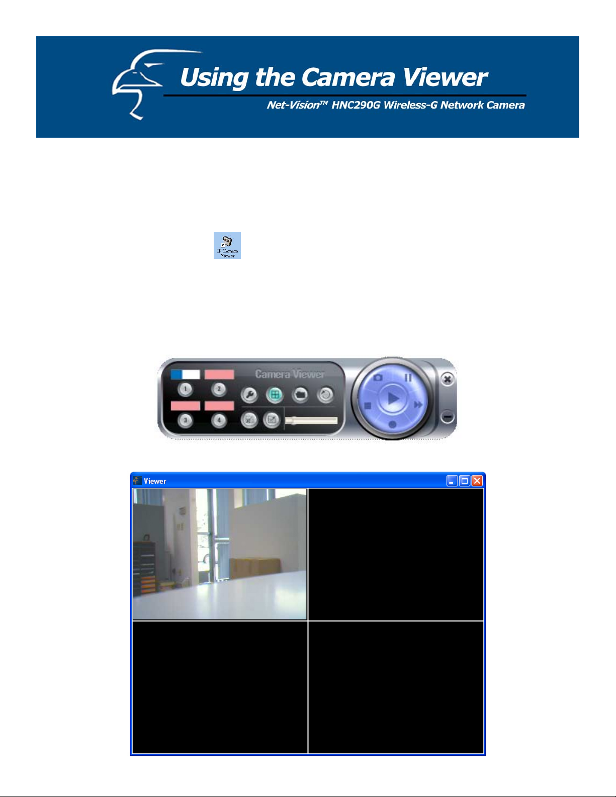
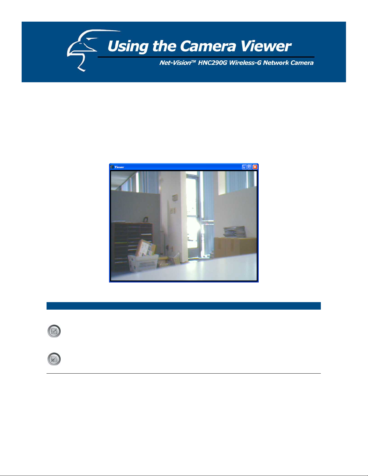
7.1 Panel Introduction
When you start the Camera Viewer, you will see a Control Panel and a Viewer window with four divisions.
39
Page 40

7.2 Camera Buttons
Camera Buttons
Camera
If you click on one of these four camera buttons, the Viewer Utility will
connect to the selected camera that you want to view and configure. If
you want to remove the camera from the viewer, please right click the
icon and select “Reset Camera x
please right click the icon and select “Configure Camera x
”. If you want to configure the camera,
”.
7.3 Camera Status
The status bar will be shown in one of four different colors to indicate the status of each connected camera.
Camera Status
Yellow This means that no camera has been set to connect to.
Blue This means that the camera is connected and playing live video.
Pink This means that the camera is not currently connected.
Red This means that the camera is recording.
40
Page 41
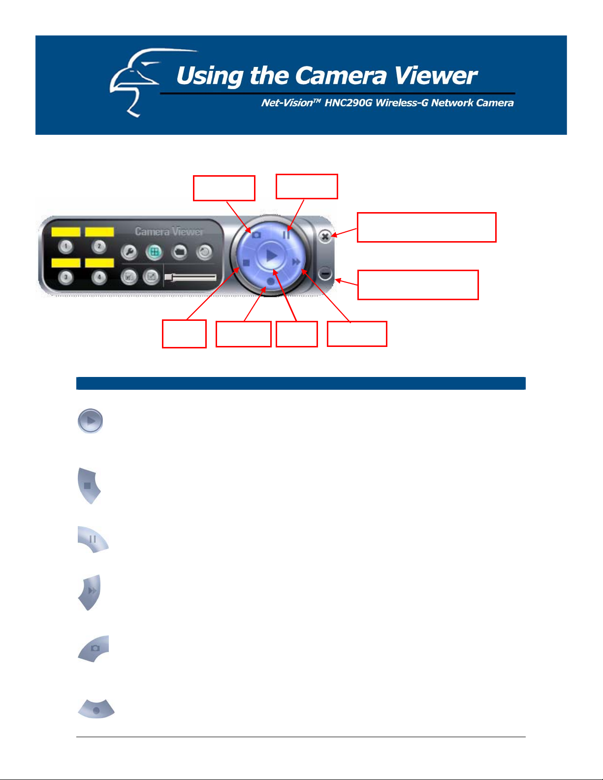
7.4 Control Buttons
Snapshot
Pause
Close the Camera Viewer
Minimize the Window
Stop
Control Buttons
Play
Stop The Stop button is an intelligent play user interface. In the normal
Record Play
The Play button is an intelligent play user interface. In the normal
display mode, if the camera is disconnected, clicking on the Play will
make the viewer connect to the camera. In playback mode, clicking on
the Play button will play the video at normal speed.
display mode, if the camera is connected, clicking on the Stop button
will make the viewer disconnect from the camera. In playback mode,
clicking on the Stop button will stop the video play.
Forward
Pause
Forward
Snapshot
Record
The Pause button provides you with a way to pause the video while it
is playing. When the video is paused, click on the Play button again to
resume the video display.
The Forward button allows the user to forward the speed of playback
when he/she is playing the recorded file. Each click of the button will
increase the playback speed one time.
Clicking the Snapshot button will make the viewer take a still-image
snapshot of the video and save it as a bitmap file in the hard disk. (You
can learn how to set the directory for storing these bitmap files in
Section 7.8.4.)
By clicking on the Record button, you can begin recording video
immediately.
41
Page 42

7.5 Video Recording
This utility allows you to record video files in AVI format. There are two ways to record video: a. Manual Recording, and
b. Schedule Recording.
Manual Recording
You can manually record the video stream into an assigned video file.
Click “Record”, and the “Record to Disk” window will appear. Assign the path and file name that you
want to save to and click “Save”. The viewer utility will then begin to record the video stream. If you
want to stop recording, click “Stop”.
Note: Before manual recording, you will need to click on the camera button (see Section 7.2 Camera
Buttons) to select the camera that you would like to record video from. You will also need to make
sure that the viewer is successfully connecting to the camera.
Schedule Recording
You can assign a schedule and let the viewer automatically record the video stream into video files.
Please refer to Section 7.8 to see how to set up recording schedules. The file name of the recorded
video file is the start time of recording. For example, the file name “IPCamera_MJPEG_2004-10-823-56-40.avi” indicates that the video file began recording on 2004/10/8 23:56:40.
42
Page 43
7.6 Change Resolution
The network camera supports two resolution formats: a. 640 x 480 (VGA), and b. 320 x 240 (CIF). You can change the
resolution of each connected network camera by clicking on the Resolution button.
Note: Before changing the network camera’s resolution, you have to select the camera by first clicking on its
corresponding camera button. If you change the resolution of one of the cameras, other clients that are viewing the same
camera simultaneously will also see the video with the changed resolution.
Resolution
VGA
CIF
Changes the resolution to 640 x 480 (VGA) mode.
Changes the resolution to 320 x 240 (CIF) mode.
43
Page 44

7.7 View Four Cameras Simultaneously
Clicking on the four-division button
window.
will allow you to view up to four cameras simultaneously in a four-division
44
Page 45

7.8 Viewer Utility Setting
Click the Setting button
. The camera’s setting window will then appear.
Note: When you want to change settings such as the IP Address, Video Port, etc. in the “Setting” option, you must first
disconnect the camera by clicking the Stop button.
7.8.1 Setting
Setting
Name It is not required that you fill in a camera name in order to connect to
the camera. It is only for users to identify the camera.
IP Address IP address/Domain name of the network camera.
Video Port The number of the service port used by the network camera.
Model Select “MJPEG Camera”. (This camera only supports Motion JPEG).
Motion Record Check this box to enable motion-triggered recording. Whenever the
camera detects motion, it will trigger a 30-second video recording. The
user is not able to change the duration of this recording. The period is
always 30 seconds.
Username The user name for logging into the network camera. By default, the
user name is “Admin”.
Password The password for logging into the network camera. By default, the
password is “1234”.
Discover Click “Discover” and the camera’s auto-discover window will appear. The
window will show all the discovered cameras on the LAN environment for
you to select.
45
Page 46

7.8.2 Recording
You can set up the schedule for recording here. This utility will automatically record the video stream in the assigned file
folder according to the schedule. The recorded video files will be in AVI format.
Note:
1. The utility will only start to record the video stream when this utility is running and is successfully connecting to the
camera at the beginning of the schedule.
2. The schedule settings for one-time and weekly should not overlap, or the recording will fail.
46
Page 47

One-Time Schedule
Weekly Schedule
Schedule
Cycle Recording Select this item to enable cycle recording. When Cycle Recording is
enabled and the storage usage has already reached the maximum reserve
storage space, the utility will automatically delete the oldest recorded video
file and use the space to store newly recorded video streams.
One-Time Schedule You can assign a range of time and the utility will automatically record
the video stream during the specified period of time only. The default
period of time is two minutes, beginning at the current time.
Weekly Schedule You can assign days of the week and the duration during those days
that you would like to record the video stream. The utility will
automatically record the video stream during the specified periods of
time. It will repeat this recording schedule every week.
New Click “New” to add a new recording schedule.
Edit Select an existing schedule in the schedule list and click “Edit” to edit
the schedule.
Delete Select an existing schedule in the schedule list and click “Delete” to
delete the schedule.
47
Page 48

7.8.3 Status
You can see the current status information of the connection session between the utility and the Internet Camera.
Status
Connected It displays “Yes” when the utility is connected to the network camera
and displays “No” when the utility is not connected to the camera.
Stream Started At This displays the time at which the current connection session between
the utility and the network camera began.
Time Elapsed This displays the elapsed time of the current connection session.
Video Received This displays the total size (units are in KB) of video stream received
during the current connection session.
Frame Rate This displays the frame rate (frames per second) of the current video
download speed from the network camera to the utility.
Data Rate This displays the data rate (KB per second) of the current video
download speed from the network camera to the utility.
Number of Frames This displays the total number of video frames received during the
current connection session.
48
Page 49

7.8.4 General
You can manage storage usage for this Internet Camera here.
General
Snap Shot Directory This lets you assign the directory where bitmap files will be stored
when you click the “Snapshot” button to take pictures. The default
folder is where the software program is installed, for example:
“C:\Program Files\Internet Camera”.
Record Directory This lets you assign the directory where the recorded video files will be
stored. The default folder is where the software program is installed, for
example: “C:\Program Files\Internet Camera”.
Free Disk Space This displays the current free disk space for the hard drive that is
assigned to save recorded files.
Max Recording Space You can reserve a certain amount of disk space to store recorded video
and snapshot files. When the disk space approaches its maximum limit,
a message will pop up to remind you.
Used Disk Space This displays the amount of disk space that is currently being used for
saving recorded files.
Max Video File Size This lets you assign a maximum size for each video file. The upper
bound for this value is 2 GB per file.
49
Page 50
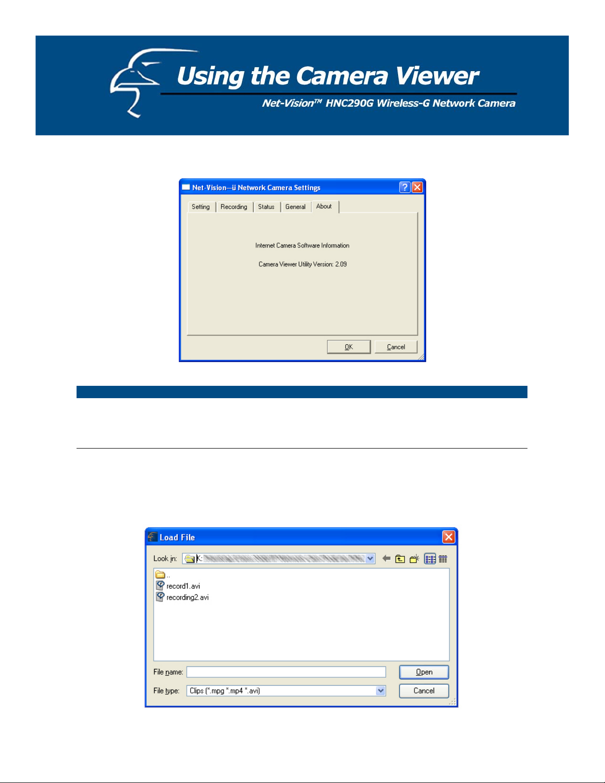
7.8.5 About
About
Camera Viewer Utility
Displays the current version of the Camera Viewer Utility.
Version
7.9 Playback
Click the “Open File” and a “Load File” window will appear. Select the file that you would like to play.
The viewer will begin playing the selected video file.
50
Page 51

Playing Control
Play
Pause
Stop
Forward
When the video playback is in the Stop state, click Play and the viewer
will play the video file from the starting point. When the video
playback is in the Pause state, click Play and the viewer will play the
video file from the current pause point. When the viewer is playing in
fast forward mode, click Play to let the viewer play at normal speed.
When recorded video is playing, you can click Pause to freeze the
playback. If you want the viewer to continue playing from the current
pause point, just click Play.
When the viewer is playing, you can click Stop to stop the playback. If
you want the viewer to play again, click Play and the viewer will play
the video file from the starting point.
If you want the viewer to play the video file at a faster speed when the
viewer is playing the video file, just click Forward and the viewer will
double the playing speed. If you want the viewer to return to playing at
normal speed, just click Play.
51
Page 52

7.10 Rotate Video
The Rotate function allows you to rotate the video frame 90 degrees counterclockwise each time you click the “Rotate”
button
. With this function, you can view live video at normal, 90-degree, 180-degree and 270-degree angles. Below
is a screenshot of video playing at a 90-degree counterclockwise angle.
52
Page 53

You can use the Web browser to connect to the camera for viewing and configuration. Open the web browser and enter
the IP Address of the camera to establish a connection. The camera’s default IP Address is “192.168.2.3”.
When the welcome screen appears, enter the “Admin Name” and “Password”. The default values are:
Admin Name: “admin”
Password: “1234”
When the camera is connected, the video image will display directly on the homepage. The menu options for the web
control screen are as follows:
Camera Settings: View live video and adjust the video format from the menu.
Network Settings: Configure the camera functions from the menu.
Wireless Settings: Configure the camera to connect to a wireless network.
Users: Up to four user-name and password sets can be created here.
53
Page 54

8.1 Camera Settings
Camera Setting
Flip
Click on “Apply” to flip the image. This feature if useful if you decide
to mount the camera upside-down.
Digital Zoom
This allows you to zoom the video size in or out. Click “x2” and the
image size in the display area will be magnified to two times the
original size. In 640 x 480 resolution, only the central area of the
screen will be magnified two times. Click “x1” and the image size in
the display area will be minimized to the original size.
Frequency Select the line frequency (50 or 60MHz) to improve the viewing quality
under fluorescent light.
Resolution Select the desired video resolution format. Please note that larger
resolution requires more bandwidth. 640 x 480 is “VGA” format. 320 x
240 is “CIF” format. The default resolution is CIF format.
OSD Format
“On-Screen Display” format. This refers to the time and date stamp on
the upper left corner of the viewing frame. The OSD will show day
and time by default. The user can select among “Disable”, “Day
Only”, “Time Only”, and “Day and Time”.
Snapshot & Mail
If you want to take a still-image snapshot of the video display, click on
this button. The system will immediately send the snapshot to the EMail account you set up in the “E-Mail Setting”.
Apply Click “Apply” to validate the “Frequency” and “Resolution” settings.
54
Page 55
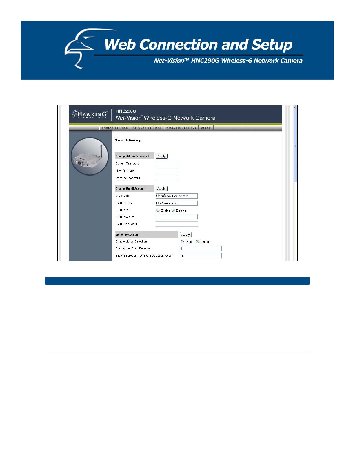
8.2 Network Settings
Change Admin Password
Current Password
Enter the current password.
New Password Type in the new password you would like to use.
Confirm Password Enter the new password again for confirmation.
Apply When you finish in the “Change Admin Password” section, click
“Apply”.
55
Page 56

Change Email Account
Email Address This camera supports the “Snapshot” function. You can snapshot a still
image and send the picture via E-Mail. Enter the E-Mail Account
where you would like to receive the picture.
SMTP Server
Enter the SMTP Server from which you would like to send the E-Mails.
Type the email address of the sender in this field.
Sender E-mail Address
If your SMTP server requires authentication, please click on the
SMTP Authentication
“Enable” radio button. Then type in the appropriate “Username” and
“Password”. (Please note that this information applies to the sender’s
SMTP server.) If you are unsure of whether or not your SMTP server
requires authentication, please check your email account settings.
Recipient Email Address This camera supports the “Snapshot” function. You can snapshot a still
image and send the picture via E-Mail. Enter the E-Mail Account
where you would like to receive the picture.
Apply
When you finish in the “Change Email Account” section, click
“Apply”.
PLEASE NOTE: Some SMTP servers require authentication via an account name (or user name) and password. You can
check this in Microsoft Outlook, for example, by clicking on the “Tools” tab on the top of your Outlook page. Once in the
“Tools” page, click on “Accounts”, then “Properties”, and then finally “Servers”.
56
Page 57

The HNC290G features built-in motion detection with snapshot emailing. In order to utilize this feature, you will have to
enable it either in the “Network Settings” section of the camera’s web UI, or in the “Motion Detection” section of the
Administrator Utility, as shown in the figure below. Once enabled, the system will email still image snapshots to the
person or party specified in the “Email Address” field, as detailed in the “Change Email Account” section from the
previous page in this user’s manual. The user can define the number of snapshots to be emailed for each detected event,
as well as the frequency with which he/she wants events to be detected. Please see the instructions below.
Motion Detection
Enable Motion Detection Motion detection is disabled by default. Click on “Enable” to begin
using the motion detection function.
Frames per Event Detection
Interval Between Next Event
Detection (secs.)
Apply
In this field, the user can select the number of still-image snapshots
he/she would like to be emailed per instance of detected motion. The
field is set at “3” by default.
In this field, the user can select the interval of time, in seconds, he/she
would like between consecutive events for motion detection. The
default setting is “10 seconds”. Please note that this camera does not
have the capability to detect motion continuously.
When you finish in the “Motion Detection” section, click “Apply”.
57
Page 58

Change IP Address
IP Address Enter an unused IP Address within the IP address range used on your
LAN. If the IP Address range of your LAN is between 192.168.2.0 and
192.168.2.250, you can set an unused IP Address from within this
range for the camera. For example: 192.168.2.250.
Subnet Mask The Subnet Mask field must match the subnet setting on your LAN. For
example: 255.255.255.0.
Gateway The Gateway is used to forward frames to destinations in a different
subnet on the Internet. The Gateway setting must be the same as the
gateway used by the PCs on your LAN.
DNS Server A DNS Server (Domain Name Server) translates names to IP addresses.
Set the same DNS Server as the PCs on your LAN.
Video Port The Video Port is used to transmit or receive the streaming video over
the network. The default port setting is “5000”. If you want to view the
video from the camera, the port setting must be correct.
Web Port This camera supports web connection. The default web port is 80.
Since the web server may use port 80, you may need to use a different
port for the camera. If you change the web port from 80 to 85, you must
type http://192.168.2.3:85 to connect to the camera through the web
browser.
Apply When you finish in the “Change IP Address” section, click “Apply”.
PLEASE NOTE: If you have DHCP enabled on your router, the LAN IP address of your network camera may
periodically change, for example when you reboot the camera, power off and power on your camera, etc. To avoid this,
you can set the LAN IP address of the camera as static by disabling the “DHCP Function” (which is enabled by default) in
the “Network Settings” page of the camera’s web UI, once you have finished installing/setting up the camera. (Again,
when you initially install the camera, either the Setup Wizard automatically assigns it an IP address or you manually
assign one in the Setup Wizard). Disabling the DHCP function will make this IP Address static. After this, the camera’s
IP address will not change unless you perform a factory default reset on it.
58
Page 59

Change Camera Name
b
Camera Name The default camera name is “HNC290G”. It is recommended that you
give the camera a name that is easy to remember.
Firmware This displays the current firmware version of the camera.
Apply When you finish in the “Change Camera Name” section, click “Apply”.
Change DDNS Setting
DDNS is an acronym for “Dynamic Domain Name Server”. Many
What is DDNS?
Internet connections use a "Dynamic IP address", where the Internet IP
address is allocated dynamically whenever the Internet connection is
established. This means that the Internet IP address can change
periodically. An Internet user would need to know his/her Internet IP
Address every time he/she wanted to connect to the camera remotely
over the Internet (i.e. from outside his/her LAN). DDNS is designed to
solve this problem, by allowing users to connect to their LANs using
domain names, rather than IP addresses. The domain name never
changes. For instance, “yahoo.com” is an example of a domain name
that corresponds to an Internet IP address. Rather than accessing this
site by typing its Internet IP address in the web address bar, users
simply type: http://www.yahoo.com
. Similarly, you can use a DDNS
service to assign a domain name for your camera.
Enable/Disable Enables or disables the camera’s DDNS function.
Provider The DDNS service for the HNC290G is provided by TZO.com.
Domain Name If you did not select a domain name for your camera in the Quick Setup
Wizard, you can do so in this field. An example of an applicable
domain name would be “homecamera.hawkingcam.com”. The first
part of the domain name, shown in the example as “homecamera”, can
e anything of your choosing. It is recommended that you choose a
word or phrase that is easy to remember. The extension “hawkingcam”
from the example is just one of several acceptable extensions. The
acceptable extensions are: “hawkingcam.com”, “hawkingcam.net”,
“myhawking.com”, “myhawkingcam.com”, and “myhawkingcam.net”.
Email Address Please enter the email address you would like to associate with your
DDNS account. This email address will be used to confirm your DDNS
settings, and to send you updates and other important information.
TZO Key Your free DDNS account will expire after 75 days from the time you
sign-up. For a small annual fee, you can continue using the DDNS
service. If you decide to renew your DDNS service, TZO will extend
your term of service (account expiration date). There is no need to
change your TZO key or account information in the camera.
DDNS Status This display will indicate if your DDNS service has expired, if a DDNS
update has completed, and other important information
Apply When you finish in the “Change DDNS Settings” section, click “Apply”.
59
Page 60

Change NTP Setting
The user can enable the NTP (Network Time Protocol) function by clicking on the “Enable”
radio button. By activating this function, you can sync the camera’s clock with one of the
time servers provided in the “NTP Server” scroll-down menu. Select the time zone from the
“Time Zone” scroll-down menu, and then select the time server in the “NTP Server” scrolldown menu. When you finish in the “Change NTP Setting” section, click “Apply”.
UPnP
Enable/Disable Enables or disables the camera’s UPnP function.
Apply When you finish in the “UPnP” section, click “Apply”.
DHCP Client
Enable/Disable Enables or disables the DHCP Client function. When this function is
enabled, the Internet Camera will automatically get an IP Address from
a DHCP Server within the network.
Apply When you finish in the “DHCP Client” section, click “Apply”.
Login Free
The Login Free feature allows the user to isolate the video frame on its own page. Please note that
this page will only show a still image of the video frame. The user can click on the web browser’s
“Refresh” button to update the image. This can be useful when trying to access quick snapshots from
the HNC290G from a cell phone, or when establishing a free Hosted Video Management account
(included with the purchase of this camera). In order to utilize this feature, you will have to:
a. Type in the desired extension in the “Login Free Filename” field in the “Network Settings”
section of the camera’s web UI, or in the “Login Free” section of the Administrator Utility, as
shown in the figure below. If you do not wish to change the extension, the default extension is
“loginfree.jpg”.
b. Type in the camera’s IP address in the “Address” bar of your web browser, followed by a
forward slash and the extension. In the example shown below, the camera’s local IP address is
10.1.1.198. Therefore, to access the Login Free page, the user would enter the following into
the address field: 10.1.1.198/loginfree.jpg. If you have changed the camera’s web port, as it
has been done in the example below (web port: 85), the user would enter the following into the
address field: http://10.1.1.198:85/loginfree.jpg
.
When you finish in the “Login Free” section, click “Apply”.
60
Page 61

Maintenance
Load Default To reset the camera to its factory default settings, click “Apply”. Then,
follow the instructions on the screen to complete the process. The
factory default settings are as follows.
Camera Name: “HNC290G”
IP Address: “192.168.2.3”
Subnet Mask: 255.255.255.0
Administrator Name: “Admin”; Password: “1234”
Video Port: “5000”; Web Port: “80”
Reboot System To reboot the camera, click “Reboot System” and then click “Apply”.
LED Light OFF/ON There are four LEDs to indicate the status of camera. If you want to
prevent the camera from being noticed, you can turn off the LED lights
by clicking “LED Light OFF” and then clicking “Apply”. To turn on
the LED lights, click “LED Light ON” and then click “Apply”.
Upgrade Firmware Clicking the “Upgrade Firmware” and “Apply” buttons will lead you to
the upgrade page. Select the “*.bin” file and click “Upgrade” to begin
upgrading. Note that the camera will stay in upgrade mode until you
finish upgrading the firmware.
61
Page 62
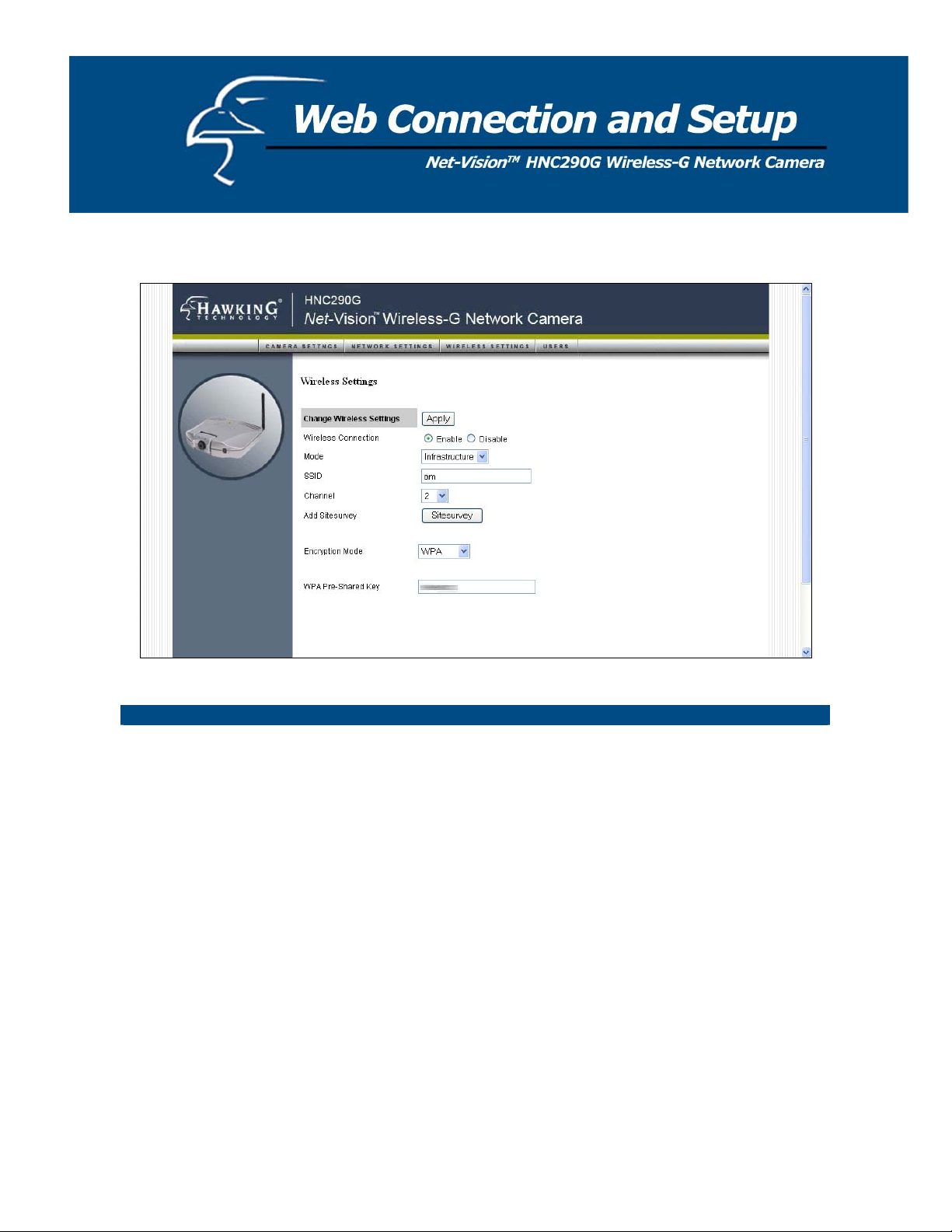
8.3 Wireless Settings
Wireless Setting
Wireless Connection Enables or disables the camera’s wireless function. By default, the
function is disabled.
Mode Infrastructure: This operation mode requires the presence of a Wireless
LAN (WLAN) Access Point or Router. All communication is done via
the Access Point or Router.
Ad-Hoc: Select this mode if you want to connect to another wireless
station in the Wireless LAN network without going through an Access
Point or Router. This is for peer-to-peer connection.
SSID The SSID (up to 32 printable ASCII characters) is the unique identifier
name for a WLAN. The ID prevents the unintentional merging of two
co-located WLANs.
You may specify an SSID for the camera’s wireless card and then only
devices with the same SSID can connect to the camera. If you want to
add an available nearby network to the profile list, pull down the menu.
All the nearby networks will be listed and you can add one of them to
the profile list.
62
Page 63

Channel This setting is only available for Ad Hoc mode. Select the number of
the radio channel used for the networking. The channel setting should
be the same as the network you are connecting to.
Site Survey Click the “Site Survey” button to search all the available wireless LAN
networks in the vicinity of the network camera.
Encryption Settings
Encryption Mode Disable: Disables the encryption function for the wireless data
communications.
WEP64: Enables the 64-bit data encryption function. If you select this
option, a set of WEP64 key fields will appear below the “Encryption
Mode” setting.
WEP128: Enable the 128-bit data encryption function. If you select
this option, a set of WEP128 key fields will appear below the
“Encryption Mode” setting.
WPA: If your wireless network uses WPA encryption, a “WPA PreShared Key” field will appear below the “Encryption Mode” setting.
You can type in your pre-shared key in this field.
Key Type (for WEP64
or WEP128)
HEX: Only the characters “A-F“, “a-f“ and “0-9“ are permitted for
HEX format.
ASCII: Numerical values, characters or signs are permitted for ASCII
format. This format is generally easier for most users.
Default Key Select one of the keys (1 - 4) as the encryption key.
Encryption Setting
Key1 - Key4 (for WEP64
or WEP 128)
The WEP keys are used to encrypt data transmitted over the wireless
network.
Fill in the fields by following the rules below:
64-bit: Input a 10-character Hex key (in the “A-F”, “a-f” and “0-9”
range) or a 5-character ASCII key (including “a-z” and “0-9”) as the
encryption key. For example: “0123456aef“ or “test1”.
128-bit: Input a 26-character Hex key (in the “A-F”, “a-f” and “0-9”
range) or a 13-character ASCII key (including “a-z” and “0-9”) as the
encryption key. For example: “01234567890123456789abcdef“ or
“administrator”.
Apply When you finish in the “Encryption Setting” section, click this button
to validate the setting values.
63
Page 64

Site Survey
Site Survey List The list displays the information of all the available wireless networks
that are in the vicinity of the camera. The information includes
Connect Status, SSID, BSSID, Signal, Channel, Encryption Setting and
Network Type.
Refresh Button Click the “Refresh” button to collect new information of all the nearby
wireless networks.
Connect Button Click “Connect” to connect to the selected network.
Close Button To close the Site Survey list, click this button.
Once you have finished making all the desired changes in the “Wireless Settings” section, be sure to click the “Apply”
button to the right of the “Change Wireless Settings” heading.
64
Page 65

8.4 Password Setting
The “Password Setting” allows users to add four user accounts who are able to view video from Camera Viewer and Web
Management. These users, unlike Administrator, are not allowed to configure the camera.
User 1 / 2 / 3 / 4
User Name Up to four sets of user names and passwords can be added. Enter the
user name to be the login name to the camera.
Password Enter up to 4 digits for the password for the new user account.
Confirm Password Enter the password again to confirm the setting.
Apply Click “Apply” to add the user account.
65
Page 66

Q1: What is an Internet/Network Camera?
A: An Internet/Network Camera is a standalone system that connects directly to an Ethernet or Wireless network. A
network or Internet camera is different from a conventional PC or web camera in that it is an all-in-one system with builtin CPU and web-server, thereby allowing the user to connect directly to the network. The user does not need to connect
the camera directly to a PC. This provides a low cost solution that can transmit high quality video images for monitoring.
An Internet/Network Camera can be managed remotely, accessed and controlled from any PC/Notebook over the Intranet
or Internet via a web browser or camera viewer (within the Intranet only).
Q2: What algorithm is used to compress the digital image?
A: The HNC290G utilizes JPEG image compression technology to provide high quality images. JPEG is a standard for
image compression and can be applied to various web browser and application software.
Q3: Can I capture or record still images from the camera?
A: Yes, you are able to capture or record still images with the snapshot function from the Camera Viewer utility.
Q4: What network cabling is required for the HNC290G?
A: The camera uses Category 5 UTP Twisted-pair cable wired Ethernet or Fast Ethernet networks. No cable is required
for wireless connection.
Q5: Can the HNC290G be setup as a PC-cam on the computer?
A: No, the camera can only be used in Ethernet, Fast Ethernet, or wireless network environments.
Q6: Can the camera be connected to the network if it consists only of private IP Addresses?
A: Yes, the camera can be connected to a LAN with private IP Addresses.
Q7: The camera focus is poor. How can I correct it?
A1: You can adjust the camera’s focus manually by rotating the focus ring (see Section 4.1 LEDs and Focusing).
Q8: There are no images available through the web browser.
A1: The Java Applet might be disabled. This sometimes happens in Windows XP Service Pack 2 and Windows Server
2003. If you are viewing the images from Internet Explorer make sure the Java Applet has been enabled in the Internet
Options menu. (Select the “Advanced” option and then “Microsoft VM”.) To download the free software, please go to
the following link: http://java.com/en/index.jsp
.
66
Page 67

Video Specifications
Max Resolution: 640 x 480 pixels
Sensor: 300,000K pixels, 1/4" color CMOS sensor
Gain control: Automatic
Exposure: Automatic
White Balance: Automatic
Focal Length: 6.0 mm
Aperture: F=1.8
Image (Video Settings)
Image compression: Motion-JPEG Image Video
Color: Digital 24-bit Color
Frame rate: 30+ fps@QCIF, 30fps@CIF, 10fps@VGA
Video resolution: 160 x 120, 320x240, 640x480
System Hardware
LAN Connector: One RJ-45 port to connect to 10/100Mbps Ethernet
Antenna Connector: One RP-SMA port to connect to antenna
LED Indicator: Power LED (Green), Link LED (Orange), LAN LED (Green), WLAN LED (Green)
Power Supply: 12VDC, 0.5A
HTTP/Utility
Includes easy-to-use Viewer & Recorder utility
Provides Admin utility & Web browser Management
View multiple cameras simultaneously - Up to 4 cameras at a time
Manual/Schedule Recording, Video Playback/Stop/Forward/Pause
Supports four additional user accounts for viewing camera
Auto Send Snapshots by E-mail
Supports DDNS and UPnP functions
Supports Windows 98SE/ME/NT/2000/XP/2003
Firmware Upgradeable
EMI & Safety
FCC, CE
67
Page 68

The steps outlined below will help you install your camera behind a router:
1. Camera Identification
Open the camera’s web page by typing its IP address in your web browser, and click on “Network Setting”. If
you intend to install multiple cameras, it is recommended that you give each camera a unique “Camera Name” in
the field provided.
2. Ensure that the Camera Has a Local IP Address
You will need a local IP address to install the camera and to be able to view it within the local area network
(LAN). If you have already installed the camera, then you will have already obtained a local IP address via the
IP Setup program or web browser. You can go back to the Quick Setup Wizard, Admin utility, or the camera’s
web page (in the “Network Settings” section) at any time to change the camera’s IP address. On the camera’s
web page, you can set the IP address under the heading “IP Address” in the “Network Settings” section. The
camera settings must correspond with your network’s existing settings. Please note that the “Gateway” is your
router’s local IP Address.
68
Page 69

3. Opening Ports
You will need to open unique ports for each camera in order to be able to view them remotely over the Internet.
You will need to open these ports in the “Network Settings” section of the camera’s homepage for two reasons:
a. if you need to use ports other than the default Web Port 80, and Video Port 5000, and b. when more than one
camera is being installed on the network. Please note that if you are using only one camera, you can use the
default ports without having to open a second port. Please also note that when installing the camera behind a
router, you will need to open the corresponding ports (same as the open camera ports) on the router for remote
viewing (i.e., over the Internet). In some instances when installing behind a router, Port 80 may not be
available; please check your network settings or with your ISP to confirm. In the “IP Setting” section within the
“Network Settings” section of the network camera’s homepage, the “Video Port” and “Web Port” fields allow
for the opening of ports for the network camera. This will permit users’ routers to support multiple network
cameras. By default, Port 80 (on the router) is always open for network camera web server access. For each
additional camera that you intend to install, to enable remote viewing, you will need to assign unique Web and
Video ports.
69
Page 70

For example, assume that you have five network cameras that need to be installed and they have the following IP
addresses:
10.1.1.125
10.1.1.126
10.1.1.127
10.1.1.128
10.1.1.129
You can open the Web port for each network camera, from port 81 to Port 85, as illustrated below:
Internet Camera 1 – IP 10.1.1.125, second “Web Server” port 81
Internet Camera 2 – IP 10.1.1.126, second “Web Server” port 82
Internet Camera 3 – IP 10.1.1.127, second “Web Server” port 83
Internet Camera 4 – IP 10.1.1.128, second “Web Server” port 84
Internet Camera 5 – IP 10.1.1.129, second “Web Server” port 85
Use a similar method to assign ports for the “Video Port”. The default, Port 5000, is open for the “Video Port”
and you can define additional ports similar to the above. If you have five cameras, you will also need to open a
unique video port for each camera. The example below illustrates how you might open the “Video Port” for five
cameras:
Internet Camera 1 – IP 10.1.1.125, “Control channel port” 5000
Internet Camera 2 – IP 10.1.1.126, “Control channel port” 5001
Internet Camera 3 – IP 10.1.1.127, “Control channel port” 5002
Internet Camera 4 – IP 10.1.1.128, “Control channel port” 5003
Internet Camera 5 – IP 10.1.1.129, “Control channel port” 5004
To view the camera over the Internet, you will need to configure your router for Port Mapping. The router’s
user manual will include instructions on how to do this. The remainder of this section will also include basic
setup instructions on how to view the camera via the Internet. Please remember that for multiple cameras, you
will need to open multiple ports per camera on your router: a. the Web port, and b. the video port.
Save/Cancel:
After making sure that all settings in the “Network Settings” sections of the network cameras’ web pages are
correct, click on the “Apply” button to store the settings for the network camera.
Steps 4 and 5 are applicable to any router you may have installed on your network.
70
Page 71

4. Locate, Make a Note of Your Router’s WAN (Public) IP Address
You will need to go to the router’s web page (by typing in its local IP address in the web address bar) and find
the “Status” (or similar) page. On this page, you should be able to locate the router’s IP address. This IP
address is the router’s public IP address and will be different from its local IP address. You will use this IP
address when enabling your camera to be viewed over the Internet. To view your camera remotely via the
Internet, it is recommended (but not required) that you assign a static IP address to your router. You will need to
contact your ISP to obtain a static IP address. When the camera is attached to the router, the static IP address
will allow you to view the camera over the Internet. If you intend to view your camera from a remote location, it
is recommended that, in a secure location, you make a note of this IP address for future reference. It is still
possible to view your camera over the Internet with a dynamic IP address (using DHCP) for your router, but this
is not the preferred method. With the dynamic option, your router’s IP address will change periodically.
Therefore, when the router’s IP address changes, unless you intend to check the router’s “Status” page regularly
or you (and all authorized viewers) know the router’s IP address at all times, you will not be able to view the
camera over the Internet. (With the dynamic option, only the router’s public IP address will change. The local
IP address will remain the same. Therefore, you will still be able to access the camera and all other clients on
the local area network from within the network.) You can also resolve the problem of a dynamic IP address by
utilizing a Dynamic DNS service.
71
Page 72

5. Use Port Mapping to Assign Virtual Server Ports
Typically, there is an “Advanced Setup” (or similar) section on the router’s web page where you can find a
“Virtual Server” or “Port Mapping” sub-section. To enable remote viewing over the Internet for your camera,
you will need to open virtual server ports on your router. The steps outlined below should be similar for most
routers:
i. Once you have located the “Virtual Server” (or similar) section, select the “By Port” method if
this option is available.
ii. Select “TCP” in the “Port Type” field.
iii. Next, select “Single” if a “Single/Range” option is available. This is so that you can open
individual ports rather than a range of them.
iv. In the “Port Number” field, enter “Port 80 to Port 80” if you intend to you use the camera’s
default port settings (discussed earlier in this Appendix). If you do not intend to use the default
settings, or if you will be using multiple cameras, you will need to enter a different port number
(i.e., 83, 84, etc.). The “Port Number” field, for example, will then read “Port 83 to Port 83”, etc.
In this case, the private Port 83 will now be opened as a public port. Please make sure that the
public and private ports match (i.e., Port 83 to Port 83). Please also remember that for multiple
cameras, you will need to open multiple ports for each camera (as discussed earlier in this
Appendix). Therefore, for the camera for which you just opened Port 83, you will also need to
open ports such as Port 5003 (Video Port). For example, in the “Port Number” field, enter “Port
5003 to Port 5003”.
v. After opening each port, click on “Add” (see figure on previous page).
72
Page 73

6. Viewing the Camera from Outside the Network
Once the settings have been correctly entered and saved, authorized users can access the camera from outside the
local area network as well as from within. To access the camera from outside the local area network in a remote
location via the Internet, type (in sequence) the router’s public IP address, a colon, and the port number assigned
to the camera, in the address bar of your web browser. For example, if your router has a public IP address of
“64.82.99.33”, you would type the following into the address bar (assuming you assigned Port 85 to the camera):
“http://64.82.99.33:85”. From within the network, you would still use the camera’s local IP address to access
the camera. For example, if you were using the local IP address “10.1.1.129” for the camera, from within the
network you would simply type: “http:// 10.1.1.129”. If you are using a web port other than the default, Port 80,
then you would type: “http://10.1.1.129:85”. (Although, typing in the router’s public IP address, followed by a
colon and port number, would work as well.)
73
Page 74
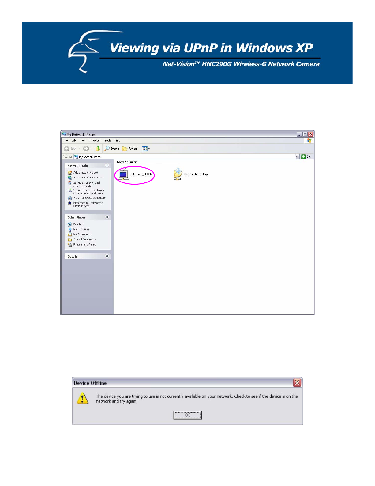
When the UPnP function is enabled, the camera can be detected by a UPnP compliant system such as Windows XP. The
camera will be displayed in “My Network Places” in Windows XP, and you can double-click on the camera directly or
right-click the camera and select “Invoke” to view the video through the web browser.
Enable UPnP in Windows XP SP2
If you cannot find the camera in “My Network Places” in Windows XP SP2 or you have seen the following message when
you double-click the camera, you will need to check if the UPnP function is blocked by a firewall. Please follow the steps
below to enable it.
1. Go to “Start\Settings\Network Connections”.
2. Right click the “Local Area Connection” and select “Properties”.
3. In the “Local Area Connection Properties”, select the “Advanced” option menu and click “Settings”.
74
Page 75
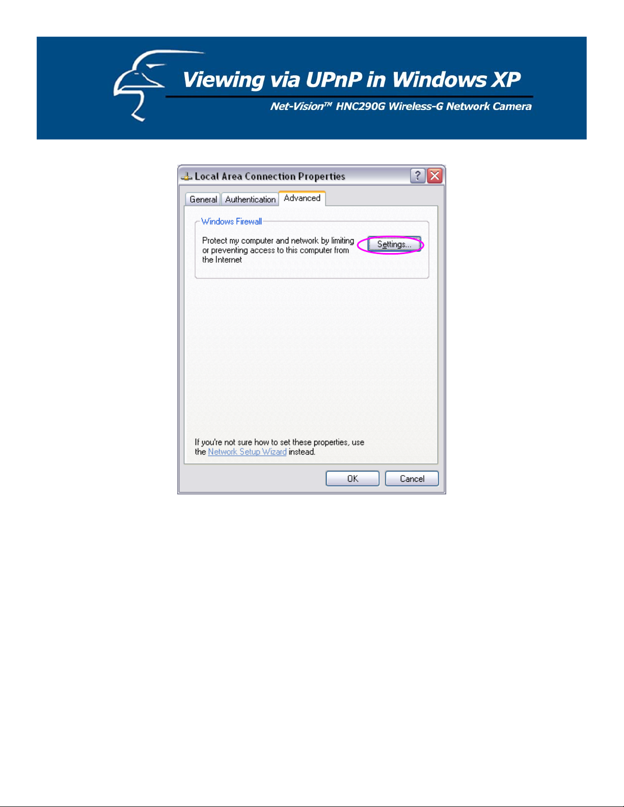
75
Page 76

4. The “Windows Firewall” screen will appear. Select the “Exceptions” option menu.
76
Page 77
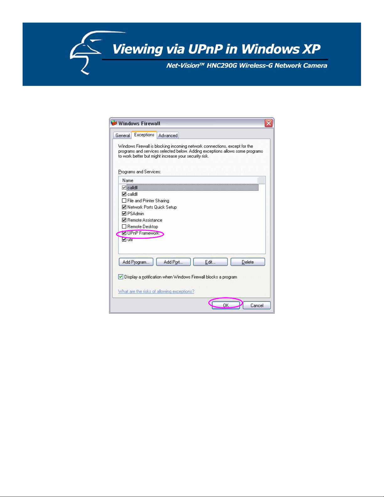
5. Enable the “UPnP Framework” from the “Programs and Services list” and click “Ok”.
77
 Loading...