

Page 1
1
Page 2

FCC Warning
This equipment has been tested and found to comply with the limits for a Class A digital device,
pursuant to Part 15 of the FCC Rules. These limitations are designed to provide reasonable
protection against harmful interference in a residential installation. This equipment generates,
uses and can radiate radio frequency energy and, if not installed and used in accordance with the
instructions, may cause harmful interference to radio communications. However, there is no
guarantee that interference will not occur in a particular installation. If this equipment does cause
harmful interference to radio or television reception, which can be determined by turning the
equipment off and on, the user is encouraged to try to correct the interference by one or more of
the following measures:
x Reorient or relocate the receiving antenna.
x Increase the separation between the equipment and receiver.
x Connect the equipment into a different outlet from the one that the receiver is connected
to.
x Consult your local distributors or an experienced radio/TV technician for help.
x Shielded interface cables must be used in order to comply with emission limits.
Changes or modifications to the equipment, which are not approved by the party responsible for
compliance, could affect the user’s authority to operate the equipment.
CE Mark Warning
This equipment complies with the requirements relating to electromagnetic compatibility, EN
55022 class A for ITE, the essential protection requirement of Council Directive 89/336/EEC on
the approximation of the laws of the Member States relating to electromagnetic compatibility.
LIMITED WARRANTY
Hawking Technology guarantees that every HGMS224 24-Port 10/100M Layer 2 Managed
Switch (Intelligent) + 2-Port Gigabit Module Slot is free from physical defects in material and
workmanship under normal use for two (2) years from the date of purchase. If the product
proves defective during this two-year warranty period, call Hawking Customer Service in order
to obtain a Return Authorization number. The warranty is for repair or replacement only.
Hawking Technology does not issue any refunds. BE SURE TO HAVE YOUR PROOF OF
PURCHASE. RETURN REQUESTS CANNOT BE PROCESSED WITHOUT PROOF OF
PURCHASE. When returning a product, mark the Return Authorization number clearly on the
outside of the package and include your original proof of purchase.
IN NO EVENT SHALL HAWKING TECHNOLOGY’S LIABILITY EXCEED THE PRICE
PAID FOR THE PRODUCT FROM DIRECT, INDIRECT, SPECIAL, INCIDENTAL OR
CONSEQUENTIAL DAMAGES RESULTING FROM THE USE OF THE PRODUCT, ITS
ACCOMPANYING SOFTWARE OR ITS DOCUMENTATION. Hawking Technology makes
2
Page 3

no warranty or representation, expressed, implied or statutory, with respect to its products or the
contents or use of this documentation and all accompanying software, and specifically disclaims
its quality, performance, merchantability, or fitness for any particular purpose. Hawking
Technology reserves the right to revise or update its products, software, or documentation without
obligation to notify any individual or entity. Please direct all inquiries to:
techsupport@hawkingtech.com
.
3
Page 4

1. Introduction 7
2. Package Contents 8
3. Hardware Installation 9
4. Initial Setup for Management 11
4.1 Out-of-band Terminal Mode Configuration 11
4.2 In-band Management through Ethernet 12
4.3 Telnet Management 14
5. Web Management 16
5.1 Web Management Home Page Overview 16
5.2 Port Status 17
5.3 Port Statistics 19
5.4 Administrator 20
5.4.1 IP Address/Subnet Mask/Gateway 20
5.4.2 Switch Settings 21
5.4.2.1 Basic 21
5.4.2.2 Module Info 22
5.4.2.3 Advanced 22
5.4.3 Console Port Information 25
5.4.4 Port Controls 26
5.4.5 Trunking 28
5.4.5.1 Aggregator Setting 28
5.4.5.2 Aggregator Information 29
5.4.5.3 State Activity 31
5.4.6 Filter Database 32
5.4.6.1 IGMP Snooping 32
5.4.6.2 Static MAC Address 34
5.4.6.3 MAC Filtering 35
5.4.7 VLAN Configuration 36
5.4.7.1 Port-based VLAN 38
5.4.7.2 802.1Q VLAN 39
5.4.8 Spanning Tree 43
5.4.9 Port Sniffer 46
4
Page 5

5.4.10 SNMP/Trap Manager 48
5.4.11 Security Manager 49
5.4.12 802.1x Configuration 50
5.4.13 Web Cluster 53
5.5 TFTP Firmware Update 55
5.6 Configuration Backup 56
5.6.1 TFTP Restore Configuration 56
5.6.2 TFTP Backup Configuration 56
5.7 Reset System 57
5.8 Reboot 57
6. Console – Firmware Update 58
7. Out-of-band Management 61
7.1 Main Menu 62
7.2 Switch Static Configuration 63
7.2.1 Port Configuration 64
7.2.2 Trunk Configuration 66
7.2.3 VLAN Configuration 68
7.2.3.1 Create a VLAN Group 70
7.2.3.2 Edit/Delete a VLAN Group 72
7.2.3.3 Group Sorted Mode 73
7.2.4 Miscellaneous Configuration 75
7.2.4.1 MAC Age Interval 76
7.2.4.2 Broadcast Storm Filtering 77
7.2.4.3 Max Bridge Transmit Delay Bound 77
7.2.4.4 Port Security 78
7.2.4.5 Collisions Retry Forever 79
7.2.5 Administration Configuration 81
7.2.5.1 Change Username 82
7.2.5.2 Change Password 82
7.2.5.3 Device Information 83
7.2.5.4 IP Configuration 83
7.2.6 Port Mirroring Configuration 84
7.2.7 Priority Configuration 85
7.2.7.1 Port Static Priority 85
7.2.7.2 802.1p Priority Configuration 86
5
Page 6

7.2.8 MAC Address Configuration 87
7.2.8.1 Static MAC Address 87
7.2.8.2 Filtering MAC Address 91
7.3 Protocol Related Configuration 95
7.3.1 Spanning-Tree Protocol 95
7.3.1.1 Enabling STP 96
7.3.1.2 STP System Configuration 97
7.3.1.3 Per Port Configuration 98
7.3.2 SNMP 99
7.3.2.1 System Options 100
7.3.2.2 Community Strings 101
7.3.2.3 Trap Managers 104
7.3.3 GVRP 107
7.3.4 IGMP 108
7.3.4.1 LACP (Link Aggregation Control Protocol) 109
7.3.4.2 Working Port Setting 109
7.3.4.3 State Activity 110
7.3.4.4 LACP Status 111
7.3.5 802.1x Protocol 112
7.3.5.1 Enable 802.1x 113
7.3.5.2 802.1x System Configuration 113
7.3.5.3 802.1x Miscellaneous Configuration 114
7.4 Status and Counters 115
7.4.1 Port Status 116
7.4.2 Port Counters 117
7.4.3 System Information 118
7.5 Reboot Switch 119
7.5.1 Default 119
7.5.2 Restart 119
7.6 TFTP Firmware Update 120
7.6.1 TFTP Firmware Update 121
7.6.2 Restore Configure File 121
7.6.3 Backup Configure File 123
8. Application Examples 125
8.1 VLAN Application Used with Switch 125
8.2 Trunking Application Used with Switch 128
6
Page 7

Hawking Technologies’ HGMS224 24-Port 10/100 Layer 2 Managed Switch (Intelligent) + 2Port Gigabit Module Slot is a high performance, web-managed SNMP (simple network
management protocol) Layer 2 switch that provides users with (24) 10/100Mbps Ethernet ports
and (2) 1000Mbps gigabit ports. The switch features SNMP management and remote control
capabilities such as “Web Cluster”. The gigabit module (available in copper media or fiber media
by special order) supports the 1000BASE-SX, 1000BASE-LX or 1000BASE-T standards, thus
allowing you to increase your network response times to gigabit speeds, as well as improve
flexibility. In addition, an RS-232 serial port provides an easy medium for installation and initial
set-up.
All ports are capable of non-blocking and maximum wire speed performance. The HGMS224
supports auto-negotiation and auto-MDIX technology on all 24 switched RJ-45 ports and both
gigabit copper ports in both half and full duplex modes. The auto-MDIX function enables the use
of either standard or crossover cables for connection with other devices.
The switch provides a convenient way to control Layer 2 management via a web browser. The
user-friendly drop-down menu allows you to easily learn, control and monitor the switch. It
supports not only traditional SNMP function, but also RMON (remote monitoring) 1,2,3,9 groups
for advanced network analysis. A new tool called “Web Cluster” can also be used to manage the
switch easily and efficiently. Using this tool, all switches can be managed via a single master
switch.
The HGMS224 also supports both port-based and tag-based VLANs. To increase bandwidth, the
switch supports 7 groups with up to 4-port trunking capabilities. These trunk ports utilize the
fair-over function to provide back up when one or more ports malfunction.
Complete front access design and a full LED status display simplify your installation, inspection,
and maintenance efforts within rack mount environments. Two extra LEDs display fan status for
quick diagnosis of over-heating issues.
7
Page 8

The complete HGMS224 package consists of:
x One HGMS224 24-Port 10/100 Layer 2 Managed Switch (Intelligent) + 2-Port Gigabit
Module Slot
x Rack mount kit: 2 mounting brackets and screws
x Four rubber feet with adhesive backing
x One AC power cord
x One RS-232 cable
x One user’s manual
x One CD
Check to make sure that the unit was not damaged during shipping and that no items are missing.
If you encounter a problem, please contact your dealer.
Please read this user’s manual thoroughly, and follow the installation and operation procedures in
the following pages.
8
Page 9

Please follow the guidelines below when choosing a location to install the switch:
x The surface must support at least 3 kg. Do not place heavy objects on the switch.
x Visually inspect the power cord and AC power connector.
x Make sure that there is proper heat dissipation from and adequate ventilation around the
switch.
Desktop or Shelf Installation:
When installing the switch on a desktop or shelf, it is recommended that you secure to the unit the
four rubber feet that are included with the package. Attach these cushioning feet to each of the
four corners at the bottom of the device. Allow adequate space for ventilation between the device
and the objects around it.
Rack Installation:
The switch can be mounted on a standard-sized, 19-inch rack that can be placed in a wiring closet
with other equipment. To install, attach the mounting brackets to the side panels of the switch and
secure them with the screws provided. Then, use the screws provided with the equipment rack to
mount the switch on the rack.
Power on:
The switch features a built-in AC power supply and operates within the following range: 90-260V
AC, 50-60Hz. The AC power connector is located at the rear of the unit. The switch’s power
supply will adjust to the local power source automatically and may be turned on without having
any or all LAN segment cables connected.
After the power switch is turned on, the LED indicators should respond as follows:
x All LED indicators will blink for a few moments. The blinking LEDs indicate a reset of
the system.
x The “Power” LED indicator will blink while the switch loads its onboard software and
performs a self-test. After approximately 20 seconds, the LED will light up again to
indicate that the switch is ready for use.
x The “100M” and “Link/Activity” LED indicators will remain lit or unlit depending on the
status of connection and activity of each port.
9
Page 10

x If the fans are working properly, the “Fan” LEDs will remain unlit. If either or both of
the fans stop or fail, the corresponding “Fan” LED(s) will be lit red.
LED Indicators
LED Color
Power
Diagnostic
Cooling
Fans
FAN1
FAN2
Green The device is powered on N/A
Green Self diagnostic successful
Red Left cooling fan failed N/A
Red Right cooling fan failed N/A
Solid Blinking
Status
Green 100Mbps Fast Ethernet connection speed N/A
100M
(Port 1-24)
Off 10Mbps connection speed N/A
10/100/1000Mbps Copper Gigabit Port (Optional Module)
Top LED
Middle LED
Bottom LED
Top + Middle
LEDs
Orange
Green
Green N/A
Orange+
Green
100Mbps Fast Ethernet connection speed
(with Middle LED off)
10Mbps Ethernet connection.
(with Top LED off)
1000Mbps Gigabit connection speed N/A
Performing self
diagnostic (after power
on)
N/A
N/A
TX/RX activity or
collision
10
Page 11

There are two ways to perform the initial setup for the Switch:
a. “Out-of-Band Configuration” - connect your PC’s serial port to the switch’s console
port with the included RS-232 serial cable and run the terminal communication
program
b. “In-Band Configuration”- network a PC to the switch and run a web browser or telnet.
The sections below show the instructions on how to perform both operations.
4.1 Out-of-band Terminal-mode Configuration
If you are using Microsoft Windows: boot up the computer, go to “Start”, “Programs”,
“Accessories”, “Communications”, and open the “HyperTerminal”. After that follow the
instructions below to set up a new terminal connection for the switch. If you are using other
communication software, please select the correct COM port and set up the connection properties
according to step #3 below.
1. Type in a name for the connection (e.g. SNMP Switch), select an icon for the connection,
and click “OK”.
2. Select the COM port that you are using for this connection and click “OK”.
3. Set up the COM port properties by using the information below and click “OK”.
Bits Rate per Second = 9600
Data Bits = 8
Parity = None
Stop Bit = 1
Flow Control = None
4. Connect the included serial cable from the computer’s COM port to the switch’s console
port.
5. Power on the switch and you will see messages displayed on the “HyperTerminal”. The
switch’s Power On Self Diagnostic (POSD) takes about 90 seconds. After that, you will see
the login screen. If the switch is already powered on and has finished its self-diagnostic, run
the terminal communication program and then hit “Enter” to get to the login screen.
6. In the User name field, type in “admin” and hit Enter.
7. In the Password field, type in “123” and hit Enter. You are now logged in to the switch’s
configuration program.
8. In the lower portion of the screen, you will see descriptions of the navigation keys (e.g.,
Tab, Spacebar, and Enter). Use these keys to navigate through the configuration program.
11
Page 12
4.2 In-band Configuration through Ethernet
In addition to terminal mode configuration, the switch also supports in-band configuration via a
web browser. Web browser configuration is easier than terminal mode configuration because the
user can simply connect the network-ready PC to the switch, open the web browser, go to the
switch’s configuration page (by typing the switch’s IP address), and configure the switch by
clicking on the subject on the menu.
Before you can access the switch via in-band tools, you must make sure the computer that is
connected to the switch has a web browser and the TCP/IP protocol (with valid IP address) is
bound to the network adapter. After that, you can either change your computer’s IP address to the
same class as the switch’s IP address, or you can log into the Switch with the “out-of-band”
method described in the previous section and configure the Switch’s IP address to the same class
as your computer’s IP address.
Below, is the Switch’s default IP information:
IP Address: 192.168.223.100
Subnet Mask: 255.255.248.0
Gateway: 192.168.223.254
12
Page 13

Modify the Switch’s IP Address via the Out-of-Band Method
1.
Log into the console (default username: admin, default password: 123).
2.
Use the Tab key to select (highlight) “Switch Static Configuration” and hit Enter.
Use the Tab key to select “Administration Configuration” and hit Enter.
3.
4.
Use the Tab key to select “IP Configuration” and hit Enter.
5.
Use the Tab key to select “Edit” and hit Enter.
6.
Use the Tab key to highlight “IP Address”, enter the desired IP address (e.g., 192.168.1.100),
and hit Enter.
7.
The “Subnet Mask” is now highlighted. Enter the correct subnet mask, and hit Enter.
8.
Input the gateway address and hit Enter.
9.
Press and hold the Ctrl key and then hit “A” to go to the “Action Menu”.
10.
Use the Tab key to select “Save” and hit Enter.
11.
The screen will prompt you to “Restart the system…” Turn off the switch, wait for 10
seconds, and then turn the switch’s power back on.
After the switch finishes the self-diagnostic, open your computer’s web browser and enter the
switch’s IP address (e.g. http://192.168.1.100) in the “Address” field. Then hit Enter or click on
Go, and the switch’s configuration page will prompt you to enter a “User Name” and Password”
to login.
(Note that the default user name is “admin” and the default password is “123”.)
Modify the Network Adapter’s IP Address
You can change the network adapter’s IP address in the “Properties” section for this device. We
suggest that you change the network adapter’s IP settings to the following:
IP Address: 192.168.223.101
Subnet Mask: 255.255.248.0
(Note: You do not need to enter the “Gateway” address at this time.)
If necessary, reboot the computer. After the computer finishes rebooting, open the web browser
and in the “Address” field, enter http://192.168.223.100. Then hit Enter or click on Go, and the
switch’s configuration page will prompt you to enter a “User Name” and Password” to log in.
(Note that the default user name is “admin”, and the default password is “123”.)
13
Page 14

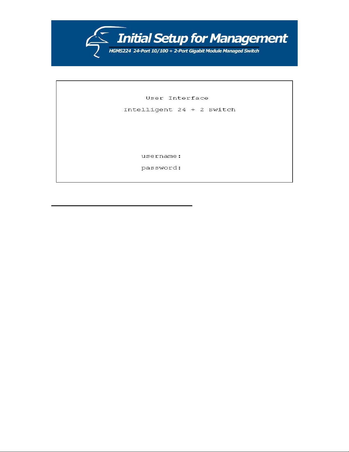
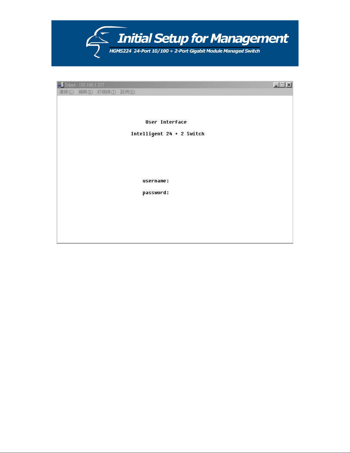
4.3 Telnet Management
In addition to local terminal mode operation, the switch supports remote management through
Telnet over the network or even over the Internet for browser-less environments. In this mode,
before executing the Telnet program, you will again be asked to modify the IP Configuration
settings as required for management via a web browser. Again, after changing the settings, save
them and connect your Ethernet cable from your PC to any port on the switch. Then, to access
the switch, simply follow the prompts in the command lines:
Telnet: IP Address for the Switch
The following dialogue below appears. Input the user name and password to proceed. Please
refer to chapter 3 of this manual to for instructions on operation in this mode.
14
Page 15
15
Page 16
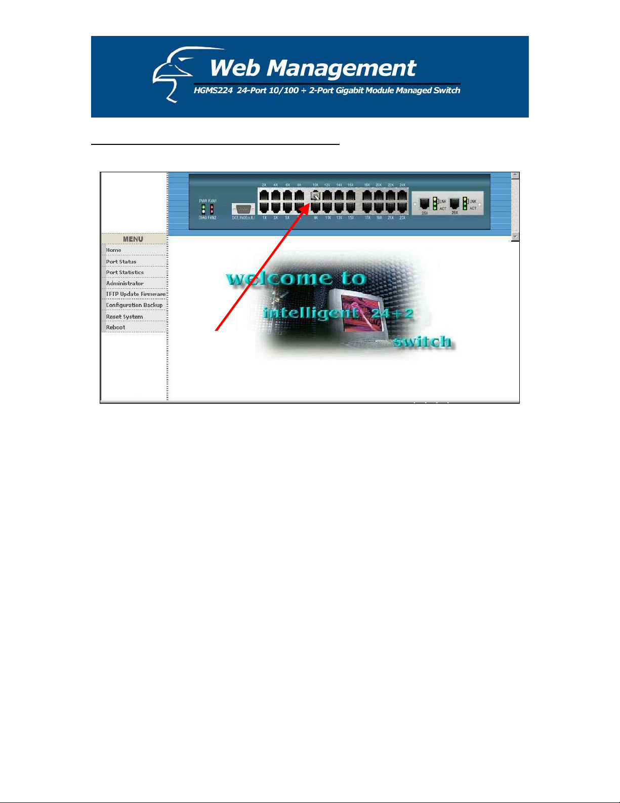
5.1 Web Management Home Page Overview
Connection
Icon
From this page, you can view the link status of every port on the switch. If a given port is linked,
it will be represented by a connection icon (see figure above) within the switch
diagram/diagnostic at the top of the page. In the column on the left side of the page, you can
click on the function names to monitor and manage the switch. The functions are listed below
and their corresponding overviews are provided in the sections immediately following the list:
1.
Port status
2.
Port Statistics
3. Administrator
TFTP Update Firmware
4.
Configuration Backup
5.
Reset System
6.
Reboot
7.
16
Page 17
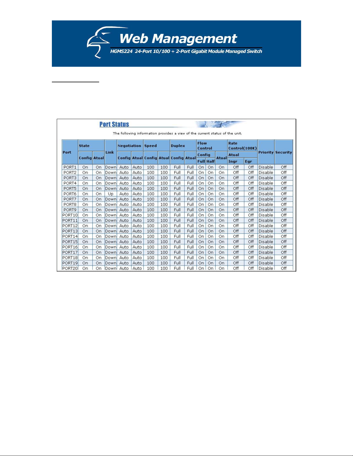
5.2 Port Status
This page provides a display of the current status of every port on the switch. The status depends
on the user settings and the negotiation results.
1. State: Displays port status: either disabled or enabled. “Unlink” will be treated as “off ”.
2. Link Status: “Down” indicates that the port is not linked, “Up” indicates that the port is
linked. (In the figure above, refer to the “Link” column for “PORT6”.)
3. [Auto]-Negotiation: Displays the auto-negotiation mode: auto/force/n-way force.
4. Speed [Status]: Displays “1000”, “100”, or “10” as corresponding to the speed. Ports 1- 24
are 10/100Mbps; ports 25-26 are 10/100/1000Mbps.
5. Duplex [Status]: Displays full-duplex or half-duplex mode.
6. Flow Control: “Full”: Displays whether flow control is enabled in full-duplex mode.
“Half”: Displays whether back pressure is enabled in half-duplex mode.
17
Page 18
7. Rate Control (100K): Displays the rate control setting.
“Ingr”: Displays the port’s effective ingress rate.
“Egr”: Display the port’s effective egress rate.
8. Port Security: Display the port security is enabled or disabled.
9. Config (located beneath the “Flow Control” category) : Displays the state of the user
settings.
10. Actual: Displays the negotiation results.
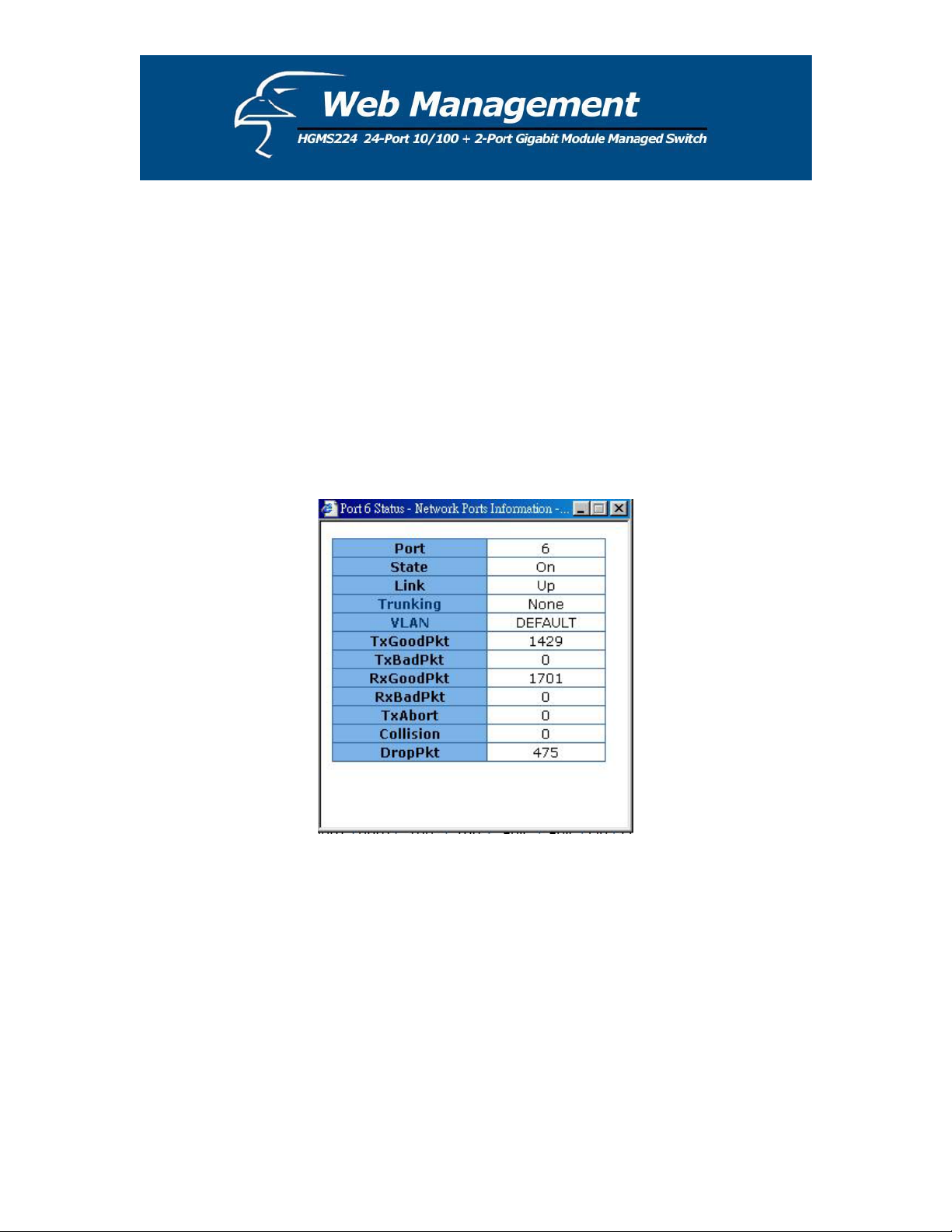
Single Port Counter and Status as Flows
You can also click on any port directly using the diagnostic of the unit’s front panel, located at
the top of the page. By doing this, you can view the status of each port individually (see figure
below).
18
Page 19
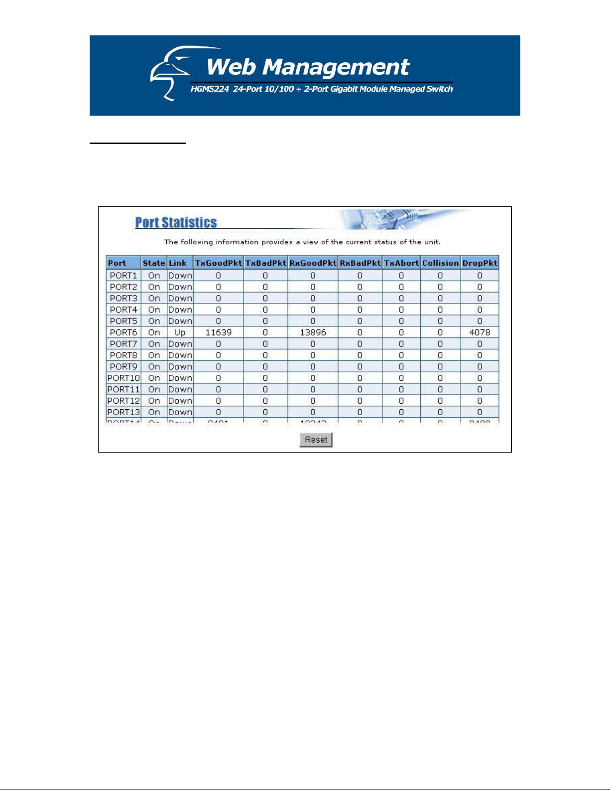
5.3 Port Statistics
This page provides a display of the current status of the entire unit. Press the Reset button to
clear all counters on this page.
19
Page 20
5.4 Administrator
Many of the management functions can be set or performed by clicking on Administrator in the
left column of the page. Once you have clicked on Administrator, you will see a menu that
includes the following categories:
IP Address
Switch Settings
Console Port Info
Port Controls
Trunking
Filter Database
VLAN Configuration
Spanning Tree
Port Sniffer
SNMP
Security Manager
802.1x Configuration
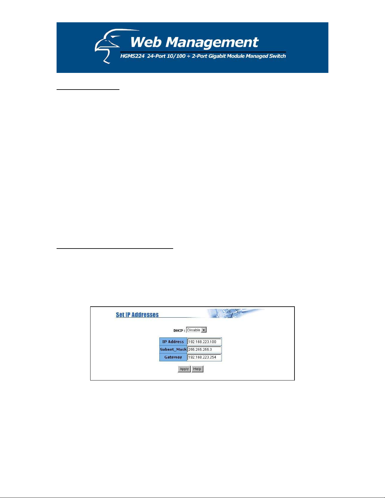
5.4.1 IP Address/Subnet Mask/Gateway
You can modify the IP settings by filling in a new value, and then clicking Apply to confirm
(save) the new settings. You must reboot the switch in order for the new IP settings to be
activated. (Please note that if any of the value are changed in this field, you must reboot the
switch.)
20
Page 21
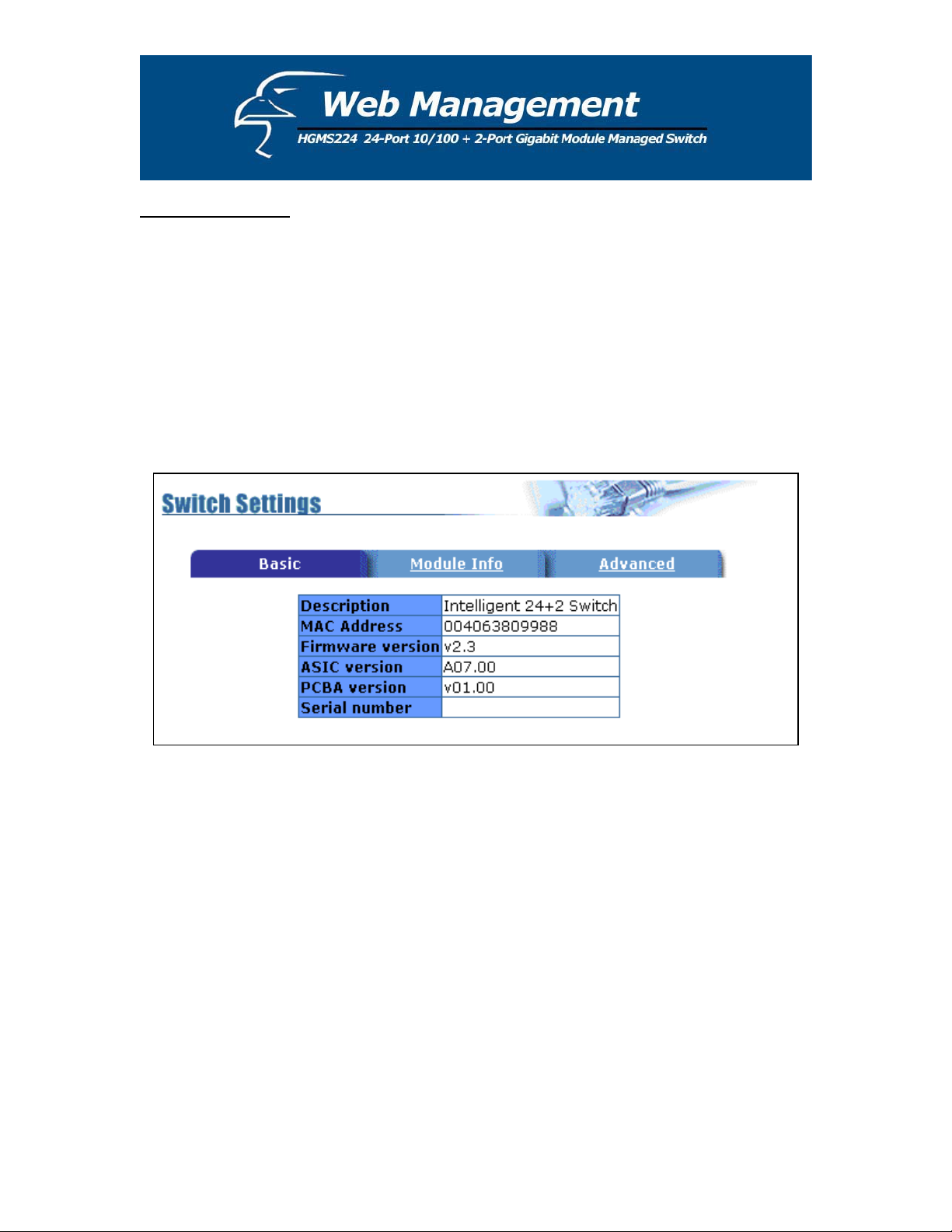
5.4.2 Switch Settings
5.4.2.1 Basic
All information in the Basic section is read-only. Therefore, you will not be able to modify its
contents.
Description: Displays what type of device you are using.
MAC Address: The unique hardware address assigned by the manufacturer (default).
Firmware Version: Displays the firmware version of the switch.
Hardware Version: Displays the hardware version of the switch.
Default Configuration Value Version: Displays the default EEPROM (Electrically Erasable
Programmable Read-Only Memory) value version.
21
Page 22
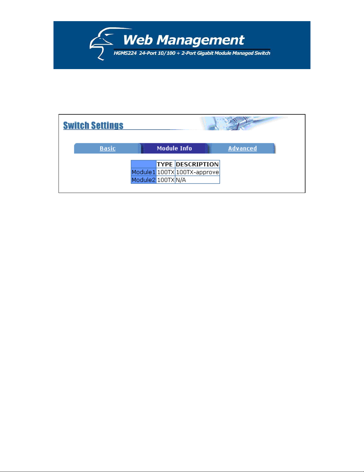
5.4.2.2 Module Info
All information in the Module Info section is read only. Therefore, you will not be able to
modify its contents. Its purpose is to display the module card information.
5.4.2.3 Advanced
Miscellaneous Settings:
MAC Table Address Entry: Age-out Time: Type in the number of seconds that an inactive
MAC address remains in the switch's address table. The valid range is 300-765 seconds. The
default is 300 seconds.
Max bridge transit delay bound control: You can limit the queuing time of the packets in
the switch. If enabled, and the packets queued exceed the time value that has been set, they
will be dropped. The valid values are 1sec, 2 sec, 4 sec and “Off”. The default value is 1
second.
NOTE: Make sure that Max bridge transit delay bound control is enabled before enabling
Low Queue Delay Bound because this function is only operable when Max bridge transit
delay bound control is enabled.
22
Page 23
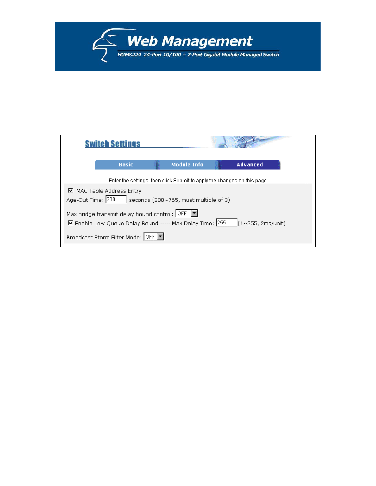
Broadcast Storm Filter Mode: To configure broadcast storm control, enable it and set the
upper threshold for individual ports. The threshold is the percentage of the port's total
bandwidth used by broadcast traffic. When broadcast traffic for a port rises above the
threshold you set, broadcast storm control becomes active. The valid threshold value are 5%,
10%, 15%, 20%, 25% and “Off”.
Priority Queue Service Settings:
First Come First Serve: The sequence of packets sent depends on the order in which they
are received.
All High before Low: The high priority packets are sent before low priority packets.
WRR: (Weighted Round Robin). Select the preference given to packets in the switch's high-
priority queue. These options represent the number of high-priority packets sent before one
low-priority packet is sent. For example, 5 High/2 Low means that the switch sends 5 high
priority packets before sending 2 low-priority packets.
23
Page 24
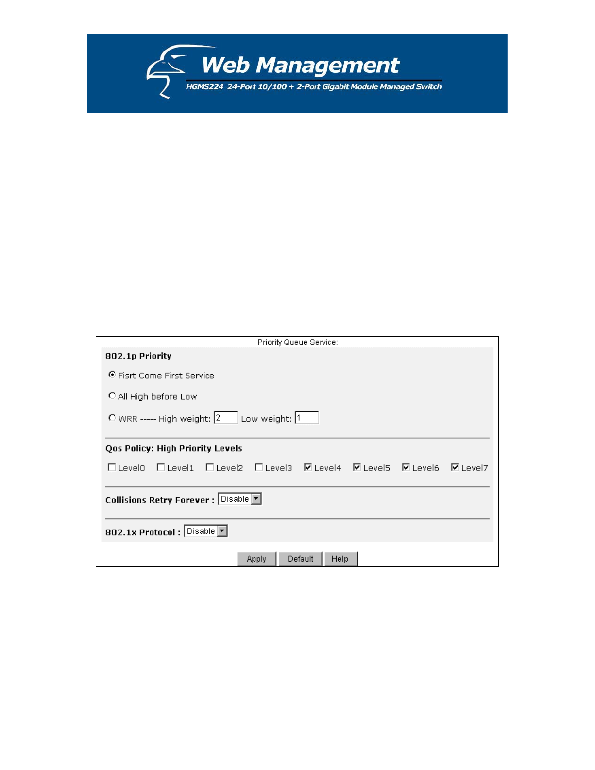
Enable Delay Bound: Limit the queuing time of low priority packets in the switch. The
default “Max Delay Time” is 255ms. If the low priority packet stays in the switch longer
than the “Max Delay Time”, it will be sent. The valid range is 1-255ms.
QoS Policy: High Priority Levels – Priority levels from 0-7 can be mapped to high or low
queues.
Collisions Retry Forever:
Disable – In half-duplex, the collision-retry maximum is 48 times, after which the packet
will be dropped if collisions continue.
Enable – In half-duplex, collisions will retry forever.
802.1x Protocol: You can enable or disable the 802.1x protocol.
24
Page 25
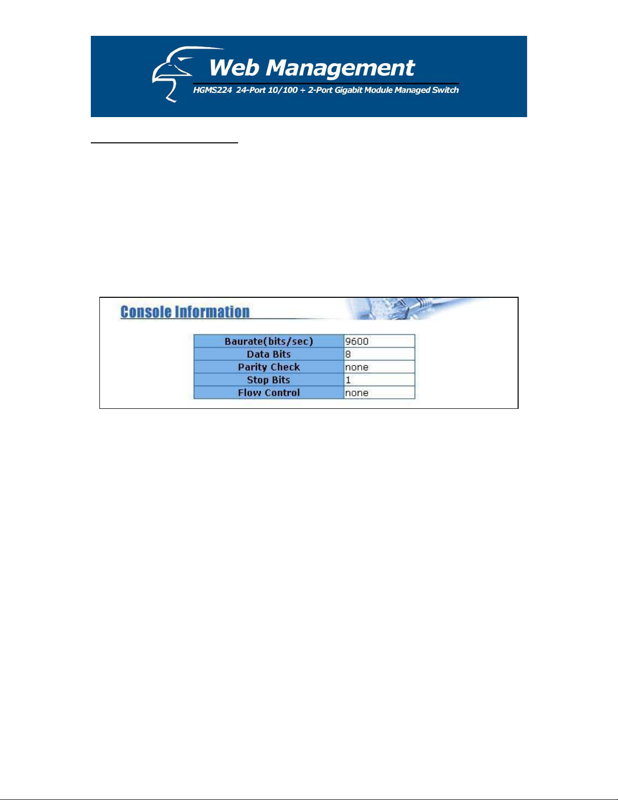
5.4.3 Console Port Information
The Console has a standard UART interface to communicate with the serial port.
You can use the Windows HyperTerminal program to establish a link to the switch.
Connect To -> Configure:
Bits per seconds: 9600
Data bits: 8
Parity: none
Stop Bits: 1
Flow control: none
25
Page 26
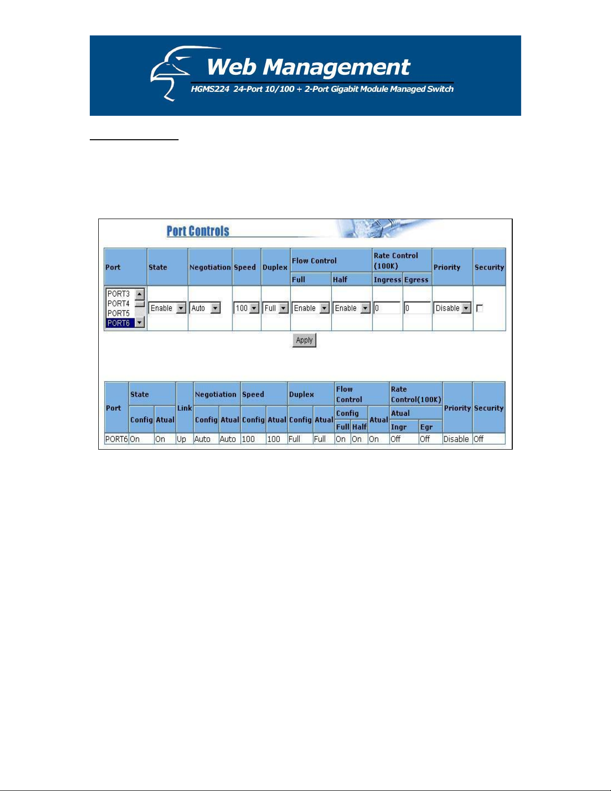
5.4.4 Port Controls
User may modify or change mode operation in this page.
1. State: You can enable or disable the port control for each port.
2. Auto Negotiation: You can set the auto negotiation mode to Auto, N-way (specify the
speed/duplex on a specific port and enable auto-negotiation), or Force for each port.
3. Speed: You can set the speed at 100Mbps or 10Mbps for Ports 1-24. You can set the speed
at 1000Mbps, 100Mbps or 10Mbps for Ports 25& 26 (depending on the module card mode).
4. Duplex: You can set each port to either full-duplex or half-duplex mode.
5. Flow control:
Full: You can enable or disable the flow control function in full-duplex mode.
Half: You can enable or disable the backpressure function in half-duplex mode.
26
Page 27

6. Rate Control: Ports 1-24 support ingress and egress rate control for each port. For example,
assume that Port 1 is set at 10Mbps. You can set its effective egress rate at 1Mbps and
ingress rate at 500Kbps. The device will perform flow control or backpressure to confine
the ingress rate to the specified rate.
Ingress: Type the effective ingress rate for a specific port. The valid range is 0 - 1000.
The units are 100K.
i. 0: disables rate control.
ii. 1 - 1000: valid rate value
Egress: Type the effective egress rate for a specific port. The valid range is 0 - 1000. The
units are 100K.
iii. 0: disable rate control.
iv. 1 - 1000: valid rate value.
7. Port Priority: This field is set at “Disable”, by default. You can set the priority of a
specific port to either “High” or “Low”.
8. Port Security: A port in security mode will be “locked” without permission of the address
learning. Only the incoming packets with SMAC already existing in the address table can be
forwarded normally. You can disable the port from learning any new MAC addresses, then
use the static MAC addresses screen to define a list of MAC addresses that can use the
secure port. Enter the settings, and then click the Apply button.
27
Page 28
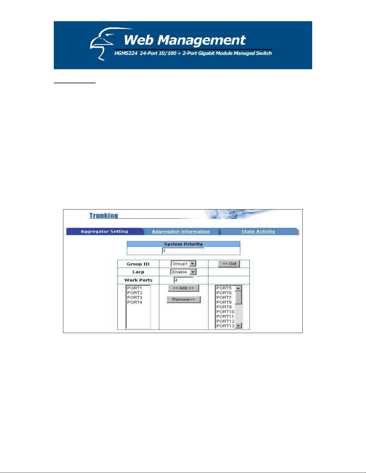
5.4.5 Trunking
The Link Aggregation Control Protocol (LACP) provides a standardized means for:
a. exchanging information between partner systems on a link, to allow their Link
Aggregation Control instances to reach agreement on the identity of the Link
Aggregation Group to which the link belongs,
b. moving the link to that Link Aggregation Group, and
c. enabling its transmission and reception functions in an orderly manner.
Link aggregation allows you to group up to eight consecutive ports into a single dedicated
connection. This feature can expand bandwidth for other devices on the network. LACP
operation requires full-duplex mode. Please refer to the IEEE 802.3ad specifications for more
details.
5.4.5.1 Aggregator Setting
1. System Priority: A value used to identify the active LACP. The switch with the lowest value
has the highest priority and is selected as the active LACP.
28
Page 29
2. Group ID: You can configure up to seven trunk groups. Choose the "Group ID" and click
"Get".
3. LACP: If enabled, the group is an LACP static trunking group. If disabled, the group is a
local static trunking group. All ports support LACP dynamic trunking groups. If connecting
to a device that also supports LACP, the LACP dynamic trunking group will be created
automatically.
4. Work ports: Allows a maximum of four ports to be aggregated into each group. If the
group is LACP static trunking, the excess ports are standby and able to aggregate if work
ports fail. If the group is local static trunking, the number of ports must be the same as the
group member ports.
5. Select the desired ports for the trunking group. (Again, the maximum number of ports per
group is four.)
6. If LACP is enabled, you can configure LACP Active/Passive status for each port. This can
be done in the “State Activity” section.
7. Click Apply.
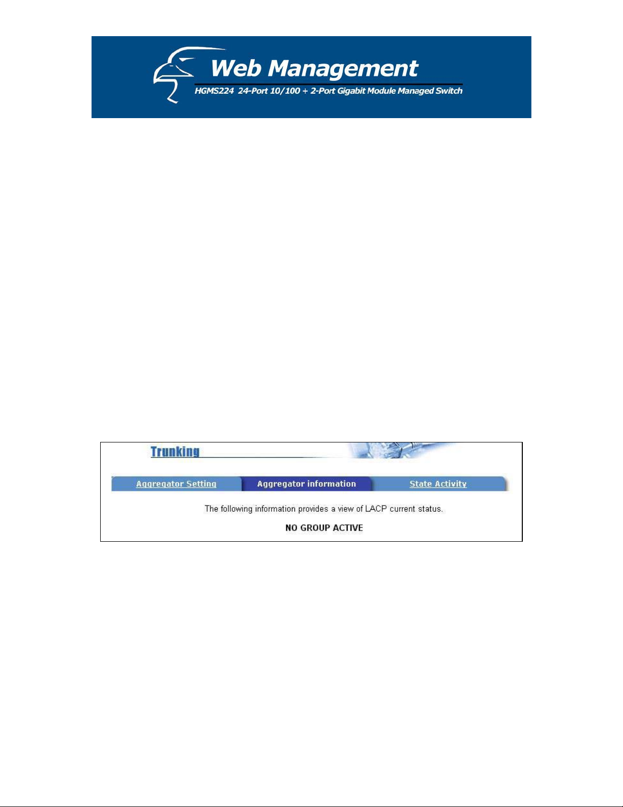
5.4.5.2 Aggregator Information
When you are configuring LACP aggregator, you can view the vital, corresponding information
in this section.
1. The page shown below is displayed when there are no active groups.
29
Page 30
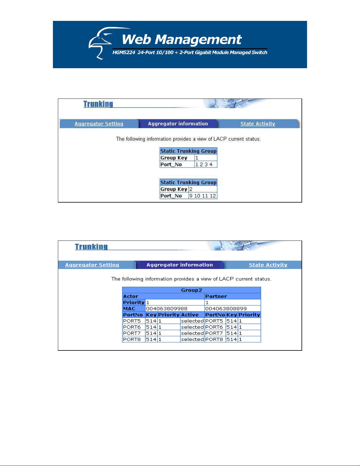
2. The page shown below displays the static trunking groups.
3. The page shown below displays “Actor” and “Partner” trunking.
30
Page 31

5.4.5.3 State Activity
Active (select): The port automatically sends LACP protocol packets.
N/A (not selected): The port does not automatically sends LACP protocol packets, and responds
only if it receives LACP protocol packets from the opposite device.
1. A link that either has two active LACP ports, or one active port can perform dynamic LACP
trunking. A link that has two ϘN/Aϙ LACP ports will not perform dynamic LACP
trunking because both ports are waiting for an LACP protocol packet from the opposite
device.
2. If the port is an active LACP actor, the active status will be created automatically when you
select port trunking.
31
Page 32

5.4.6 Filter Database
5.4.6.1 IGMP Snooping
The switch supports IP multicasting. You can enable the IGMP protocol in the “IGMP
Snooping” section. IGMP snooping information is displayed on this page. You can view
different multicast groups, VIDs and member ports in this section. IP multicast addresses range
from 224.0.0.0 to 239.255.255.255.
32
Page 33

The Internet Group Management Protocol (IGMP) is an internal protocol within the Internet
Protocol (IP) suite. The IP suite manages multicast traffic by using switches, routers, and hosts
that support IGMP. Enabling IGMP allows the ports to detect IGMP queries and report packets,
and manage IP multicast traffic through the switch. IGMP has three fundamental types of
messages, shown below:
Message Description
Query
A message sent from the queries (IGMP router or switch) asking for a response
from each host belonging to the multicast group.
Report
A message sent by a host to the queries to indicate that the host wants to be or
already is a member of a given group cited in the report message.
Leave Group
A message sent by a host to the queries to indicate that the host is no longer a
member of a specific multicast group.
33
Page 34

5.4.6.2 Static MAC Address
When you add a static MAC address, it remains in the switch's address table, regardless of
whether or not the device is physically connected to the switch. This saves the switch from
having to re-learn a device's MAC address when the disconnected or powered-off device is active
on the network again.
1. Click on the “Static MAC Addresses” tab.
2. In the MAC address box, enter the MAC address to and from which the port should
permanently forward traffic, regardless of the device’s network activity.
3. In the “Port num” box, enter a port number.
34
Page 35

4. If tag-based (IEEE 802.1Q) VLANs are set up on the switch, static addresses are associated
with individual VLANs. Type in the VID (tag-based VLAN ID) to associate with the MAC
address.
5. Click the Add button.
5.4.6.3 MAC Filtering
MAC address filtering allows the switch to drop unwanted traffic. Traffic is filtered based on the
destination addresses.
1. In the MAC Address box, enter the MAC address that you want to filter.
2. If a tag-based (802.1Q) VLAN is set up on the switch, type the VID in the VLAN ID box to
associate with the MAC address.
3. Click the Add button.
4. Choose any MAC addresses that you want to delete and then click the Delete button.
35
Page 36

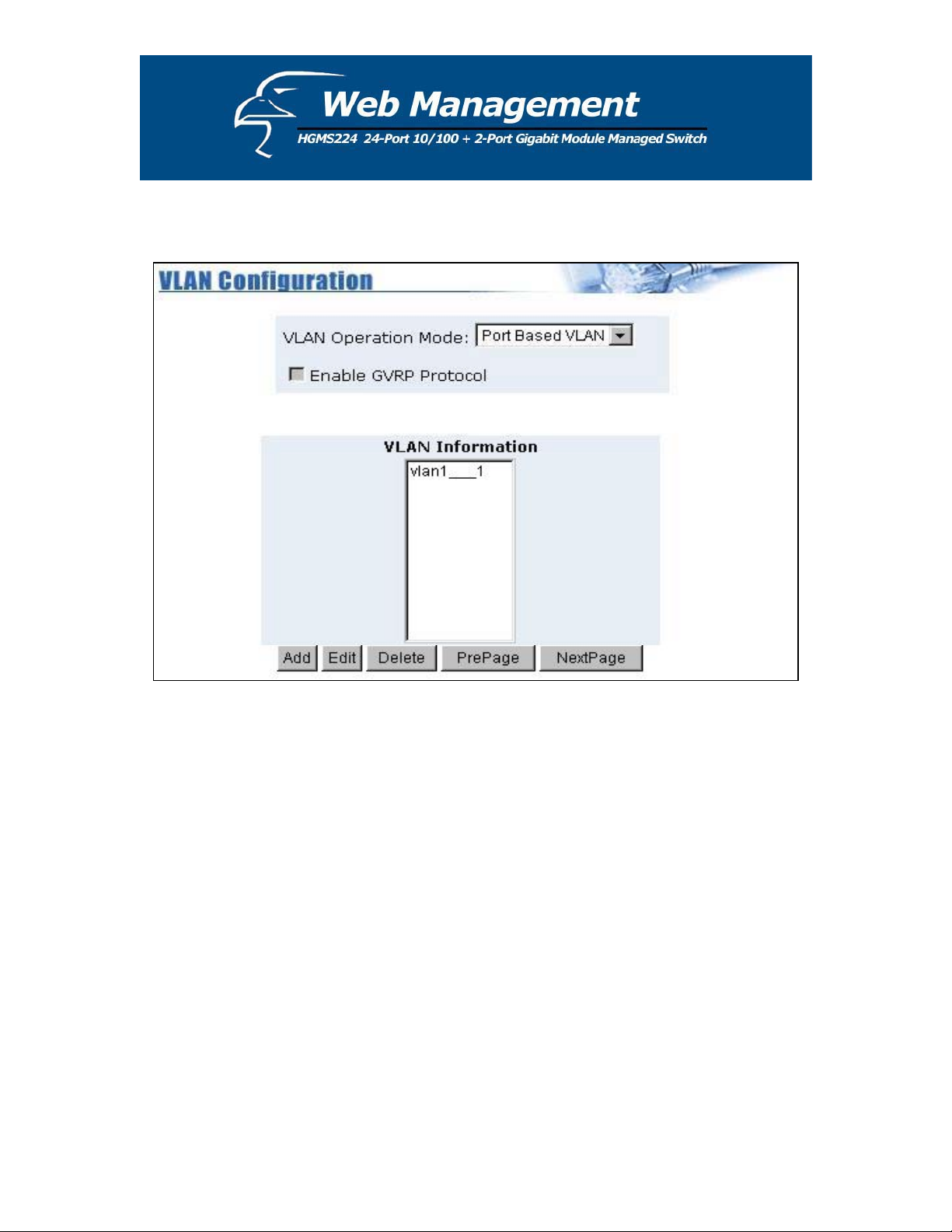
5.4.7 VLAN Configuration
A Virtual LAN (VLAN) is a logical network grouping that limits the broadcast domain. It allows
you to isolate network traffic so only members of the VLAN receive traffic from the same VLAN
members. Basically, creating a VLAN from a switch is logically equivalent to reconnecting a
group of network devices to another Layer 2 switch. However, all the network devices are still
physically plugged into the same switch.
The switch supports port-based, 802.1Q (tag-based) and protocol-based VLAN through web
management. In the default configuration, VLAN support is disabled.
36
Page 37
Port-based VLAN
Packets can only be broadcast among members of the same VLAN group. Note that all
unselected ports are treated as belonging to another single VLAN. If the port-based VLAN is
enabled, the VLAN-tagging is ignored.
37
Page 38

Tag-based VLAN (IEEE 802.1Q VLAN)
Tag-based VLAN is an IEEE 802.1Q specification standard. Therefore, it is possible to
create a VLAN across devices from different switch vendors. IEEE 802.1Q VLAN uses a
technique to insert a “tag” into the Ethernet frames. Tags contain a VLAN Identifier (VID)
that indicates the VLAN numbers.
Protocol-based VLAN
In order for an end station to send packets to different VLANs, it must either itself be
capable of tagging packets it sends with VLAN tags or be attached to a VLAN-aware bridge
that is capable of classifying and tagging the packet with different VLAN IDs based not only
on default PVID but also on other information about the packet, such as the protocol. The
switch will support protocol-based VLAN classification by means of both, built-in
knowledge of Layer 2 packet formats used by selected popular protocols, such as Novell IPX
and AppleTalk’s EtherTalk, and some degree of programmable protocol matching capability.
38
Page 39
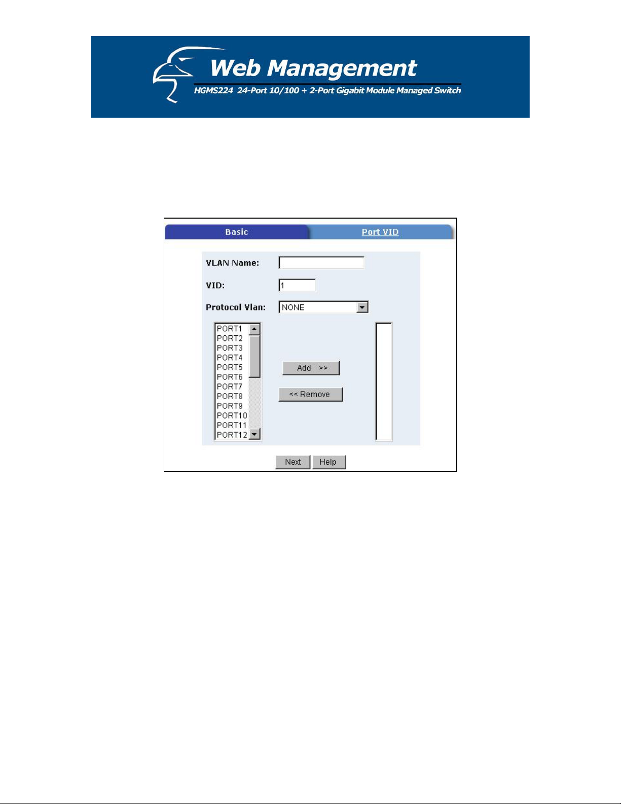
5.4.7.1 Port-Based VLAN
1. Click Add to create a new VLAN group.
2. Enter the VLAN name and group ID, and select the members for the new VLAN.
3. Click Apply.
4. If there are more groups than the viewable box can display, you can click Next Page to view
other VLAN groups.
NOTE:
If the trunk groups already exist, you can view them (ex: TRK1, TRK2…) in the menu of ports
(see the section titled, “Basic” in the pages that follow), and you can configure them as the
members of a VLAN.
39
Page 40

5.4.7.2 Tag-based (IEEE 802.1Q) VLAN
This page, user can create Tag-based VLAN, and enable or disable GVRP protocol.
There are 256 VLAN groups to provide configure. Enable 802.1Q VLAN, the all ports on the
switch belong to default VLAN, VID is 1. The default VLAN can’t be delete.
GVRP (GARP [Generic Attribute Registration Protocol] VLAN Registration
Protocol)
GVRP allows automatic VLAN configuration between the switch and corresponding
nodes. If the switch is connected to a device with GVRP enabled, you can send a GVRP
request using the VID of a VLAN defined on the switch. The switch will automatically
add the device to the existing VLAN.
40
Page 41
Basic
Create a VLAN and add tagged member ports to it.
1. Click on the “Basic” tab, and then click Add to reach the page shown below.
2. Type a name for the new VLAN.
3. Type a VID (between 2-4094). The default is 1.
4. Choose the protocol type.
5. From the column box on the left that displays the available ports, select the ports you
would like to add click Add >>. If the trunk groups already exist, you can view them here
(ex: TRK1, TRK2…) and configure them as the members of a VLAN.
41
Page 42

6. Click Next. Then you can view the page as follows:
7. Use this page to set the outgoing frames as VLAN-tagged frames, if necessary. Then
click Apply.
Tag: outgoing frames that are VLAN-tagged.
Untag: outgoing frames that are not VLAN-tagged.
42
Page 43

Port VID
Configure Port VID Settings
From the main tag-based (IEEE 802.1Q) VLAN page, click the “Port VID” tab.
Port VID (PVID)
Set the port VLAN ID that will be assigned to untagged traffic on a given port. This feature
is useful for accommodating devices that you want to participate in the VLAN but that don’t
support tagging. Each port allows you to set one PVID; the range is 1-255 and the default
PVID is 1. The PVID must be the same as the VLAN ID of the port that belongs to the
VLAN group, or the untagged traffic will be dropped.
43
Page 44
Ingress Filtering
Ingress filtering allows frames that belong to a specific VLAN to be forwarded if the port
belongs to that VLAN. The switch has two ingress filtering rules. They are as follows:
Ingress Filtering Rule 1: Only forward packets with VIDs matching this port’s configured
VID.
Ingress Filtering Rule 2: Drop untagged frames.
5.4.8 Spanning Tree
The spanning-tree protocol (STP) is a standardized method (IEEE 802.1D) for avoiding loops in
switched networks. Enabling STP will ensure that only one path at a time is active between any
two nodes on the network. You can enable the spanning-tree protocol on the “Switch Settings”
page in the “Advanced” section. Select “Enable Spanning-Tree protocol”. We recommend that
you enable STP on all switches to ensure a single active path on the network.
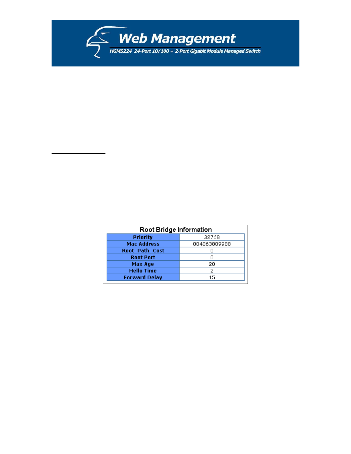
1. You can view spanning tree information about the Root Bridge. A sample is shown below.
44
Page 45
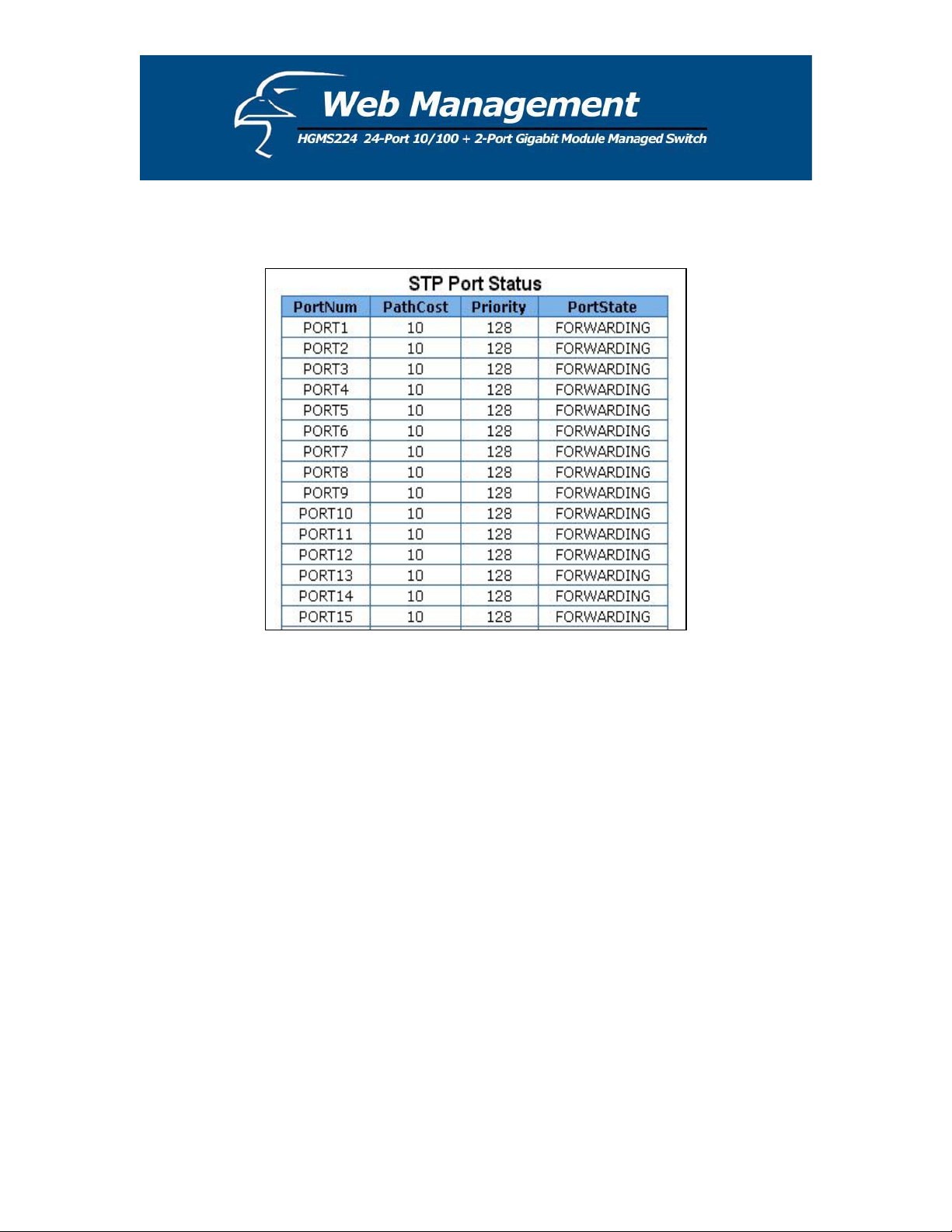
2. You can also view the spanning tree status of the switch. A sample is shown below.
45
Page 46
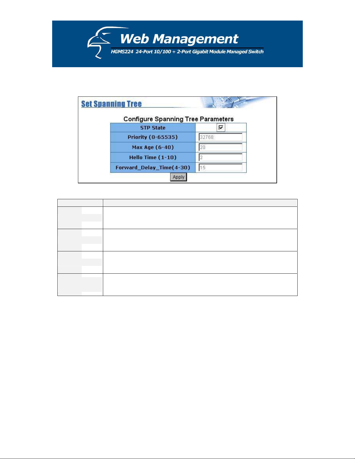
3. You can change the settings for the STP parameters. Then click Apply.
Parameter Description
You can change the priority value, which is a value used to identify the
Priority
root bridge. The bridge with the lowest value has the highest priority and is
selected as the root. Enter a number between 1 and 65535.
You can change the max age value, which is the number of second bridge
Max Age
waits without receiving spanning-tree protocol configuration messages
before attempting a reconfiguration. Enter a number between 6 and 40.
You can change the Hello Time value, which is the number of seconds
Hello Time
between the transmissions of spanning-tree protocol configuration
messages. Enter a number between 1 and 10.
Forward Delay
Time
You can change the forward delay time, which is the number of seconds a
port waits before changing from its spanning-tree protocol learning and
listening states to the forwarding state. Enter a number between 4 and 30.
46
Page 47

4. The following parameters can be configured on each port. Click Apply after you have made
the appropriate changes.
Parameter Description
Port Priority
You can increase the priority level for a port to become the root port. The
range is 0-255, and the default setting is 128. The lowest number has the
highest priority.
This parameter specifies the path costs of the ports that the switch uses to
Path Cost
determine which ports are the forwarding ports. The ports with the lowest
numbers are the forwarding ports. The range is 1-65535, and the default
value is bases on the IEEE 802.1D specifications: 10Mb/s = 50-600,
100Mb/s = 10-60, 1000Mb/s = 3-10
5.4.9 Port Sniffer
The port sniffer is a tool for monitoring traffic in switched networks. Traffic through ports can be
monitored via one designated port. Traffic going in or out of monitored ports will be duplicated
into a sniffer port.
1. Sniffer Mode: Press Spacebar to set the sniffer mode to: Disable \Rx \Tx \Both.
2. Monitoring Port: The sniffer port can be used to monitor port traffic. You can connect the
sniffer port to a LAN analyzer or NetXRay.
47
Page 48

3. Monitored Port: The ports you want to monitor. All monitor port traffic will be copied to
sniffer port. You can select max 25 monitor ports in the switch. User can choose which port
that they want to monitor in only one sniffer mode.
If you want to disable the function, you must select “None” in the “Analysis Port” category.
48
Page 49

5.4.10 SNMP/Trap Manager
Any network management platform that is running the Simple Network Management Protocol
(SNMP) can manage the switch, provided the Management Information Base (MIB) is installed
correctly on the management station. SNMP is a protocol that governs the transfer of information
between management station and agent.
1. System Options: You can define a name, location, and contact person for the switch. Fill in
the system options data, and then click Apply to update the changes on this page.
Name: Enter a name to be used for the switch.
Location: Enter the location of the switch.
Contact: Enter the name of a person or organization.
2. Community sSrings: serve as passwords and can be entered as one of the following:
RO: Read-only - enables requests accompanied by this string to display MIB-object
information.
RW: Read-write - enables requests accompanied by this string to display MIB-object
information and to set MIB objects.
49
Page 50

3. Trap Managers: A trap manager is a management station that receives traps, which are the
system alerts generated by the switch. If no trap manager is defined, no traps are issued.
Create a trap manager by entering the IP address of the station and a community string.
5.4.11 Security Manager
On this page, you can change the user name and password as follows:
1. User name: Type the new user name.
2. Password: Type the new password.
3. Reconfirm password: Retype the new password.
4. Click Apply.
50
Page 51

5.4.12 802.1x Configuration
System Configuration
802.1x makes use of the physical access characteristics of IEEE 802 LAN infrastructures in order
to provide a means of authenticating and authorizing devices attached to a LAN port that has
point-to-point connection characteristics, and of preventing access to that port in cases in which
the authentication and authorization process fails.
To enable 802.1x, go to Administrator > Switch Settings > Advanced. You can enable 802.1x
at the bottom of the page. After enabling 802.1x, proceed to the “802.1x Configuration” section
to fill in the authentication server information.
Radius Server IP Address: The IP address of the authentication server.
Server Port: The UDP port number used by the authentication server to authenticate.
Accounting Port: The UDP port number used by the authentication server to retrieve accounting
information.
Shared Key: A key shared between this switch and the authentication server.
NAS, Identifier: A string used to identify this switch.
51
Page 52
Per Port Configuration
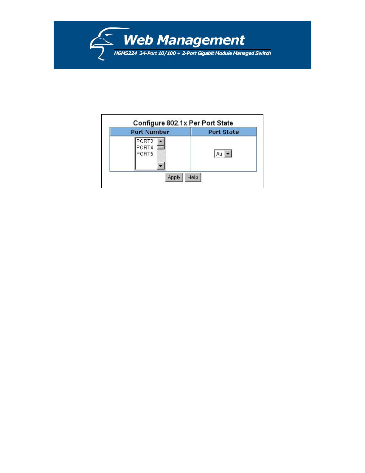
In this page, you can select a specific port and configure the authorization state.
You can select from a list of four authorization states for each port:
Fu: Forces a specific port to be unauthorized.
Fa: Forces a specific port to be authorized.
Au: The state of a specific port is determined by the outcome of the authentication.
No: The selected port is not 802.1x enabled.
52
Page 53

Misc Configuration
In this page, you can change the default configuration for the 802.1x standard:
Quiet Period: Used to define periods of time during which it will not attempt to acquire a
supplicant (default time is 60 seconds).
Tx Period: Used to determine when an EAPOL PDU is to be transmitted (default value is 30
seconds).
Supplicant Timeout: Used to determine timeout conditions in the exchanges between the
supplicant and authentication server (default value is 30 seconds).
Server Timeout: Used to determine timeout conditions in the exchanges between the authenticator
and authentication server (default value is 30 seconds).
Re-Auth Max: Used to determine the number of re-authentication attempts that are permitted
before a specific port becomes unauthorized (default value is 2 times).
Re-Auth Period: Used to determine a non-zero number of seconds between periodic reauthentication of the supplications (default value is 3600 seconds).
53
Page 54

5.4.13 Web Cluster
This switch provides a new management tool for you to manage a group of LAN switches
through a master switch. It is called the “Web Cluster” function. This function allows the
manager switch (also called “master switch”) to fetch the web pages from the managed switches
to the user ‘s browser. The MIS can store information about up to 16 sets of other switches in
one master switch, and easily switch to the web page of the desired Ethernet switch without
remembering the IP of the host. Moreover, the switch has no exclusiveness, meaning that the
MIS can group switches of any brand and the web cluster switch will not reject any other switch
from any other brand.
Web Cluster Menu
A pop-up menu will be displayed after clicking the “Web Cluster” item in the main menu.
54
Page 55

There are 16+1 rows in the web cluster menu. The top row, with the deep blue background,
indicates the master switch IP and cannot be modified. The other 16 rows, in a lighter blue
background, can be added with managed switches by clicking Add/Del Switches.
In the row, there is specific information about the managed switch: host names and their IPs. If
the host is a Web Cluster-supported switch, an asterisk (*) will appear before the host name. The
current managed switch will be highlighted in red on the menu. You can switch to another host
by clicking on it and the browser window will jump to its homepage.
Web Cluster setting
In this page, you can add or delete web cluster group members. There is a list in the “Web
Cluster Status” section, indicating the current group setting. Hosts in blue font are Web Clustersupported.
A
dd: Enter the IP and name of the switch to be added. If the switch is Web Cluster-supported,
c
lick the checkbox “Web Cluster Support”. The default setting is “Off”. After clicking Add, the
in
put host will be added to the “Web Cluster Status” list.
D
elete: In the “Web Cluster Status” list, click the Del checkbox for items to be removed. After
th
at, click Delete to refresh the list.
A
pply: When the list is confirmed, click Apply to submit. The web cluster menu list will be
u
pdated. The group information will be stored in the master switch.
N
ote:
“
Web Cluster-supported” indicates that, if the managed host is also a Web Cluster switch, the
m
aster switch will bypass the password authentication and suppress the “Web Cluster” item in the
m
anaged host’s main menu.
55
Page 56

5.5 TFTP Firmware Update
The following menu options provide some system control functions to allow you to update the
rmware and remote boot switch system:
fi
x Install the TFTP program (such as Turbo98, or Cisco TFTP) and then execute.
x Copy updated firmware image. bin into the TFTP server’s directory.
x Using the web management tool, select “TFTP Update Firmw
x new image.bin file by clicking Apply.
Download the
x After the upda
te is completed, click Reboot to restart the switch.
are”.
56 56
Page 57

5.6 Configuration Backup
5.6.1 TFTP Restore Configuration
Use this page to set the FTP server address. You can restore the EEPROM value from here, but
you u image.
m st put the image back in the FTP server; the switch will download back the flash
.6.2 TFTP Backup Configuration
5
se this page to set the TFTP server IP address. You can save the current EEPROM value from
U
ere, and then go to the “TFTP Restore Configuration” page to restore the EEPROM value.
h
57
Page 58

5.7 Reset System
In this page, you can reset the switch to its default configuration. The default value is shown
elow.b
.8 Reboot5
this page, you can reboot the switch in software reset.In
58
Page 59

Console - 1K Xmodem Firmware Update
We provide a 1k Xmodem to update the firmware via the console. The X modem only works in
57600bp
here are two situations in which to use the 1K X modem to update the firmware:
T
. You can enter "1K X modem receiver mode" by pressing any key within 5 seconds of the
1
. The system automatically enters "1K X modem receiver mode" if it detects the firmware
2
. Press the “Disconnect” button when you start 1K X modem modes.
1
s mode. So you must change the baud rate to 57600bps to download the firmware.
system power being turned on.
checksum failed while booting.
Go to File -> Properties, change the baud rate to 57600bps, and then click OK.
59
Page 60

2. Press the “Connect” button and you will see “CCCC…”displayed on the console.
Then go to Transfer > Send File.
3. Select 1K Xmodem under the Protocol item, and list the directory for the image file folder.
Then click Send.
60
Page 61

4. Start downloading the image file.
5. Finish downloading the file and the switch system will update the firmware automatically. If
the message “Update firmware…ok…” appears, the switch will reboot. Please change the
baud rate to 9600bps.
61
Page 62

Out-of-band Terminal Mode Management
. The switch also provides a serial interface to manage and monitor the switch. You can follow
1
the steps outlined in the “Console Port Info” section of the web interface for using the
Windows HyperTerminal program to link the switch.
2
. You can type a user name and password to login. The default user name is “admin” and the
default password is “123 ”.
62
Page 63

7.1 Main Menu
The
re are six selectable items, as shown below:
Switch Static Configuration: Allows you to configure the switch.
Protocol Related Configuration: Allows you to configure the protocol function.
Status and Counters: Displays the status of the switch.
Reboot Switch: Allows you to restart the system or reset switch to its default configuration.
TFTP Update Firmware: Uses TFTP to download the updated firmware.
Logout: Exits the menu line program.
The control key can be used as follows for this mode of operation:
Tab: Moves to the next item.
Backspace: Moves to the previous item.
Enter: Selects the item.
Spacebar: Toggles between the selectable items.
63 63
Page 64

7.2 Switch Static Configuration
ou can press the Tab or Backspace keys to choose an item, and then press Enter to select the
Y
item. The action menu, shown below, applies for configuration in t
<Quit>: Allows you to exit the current page and return
to previous menu.
his section.
<Edit>: Configures all of the items. Once you have completed making the appropriate chang
press Ctrl + A to return to the action menu line.
<Save>: Saves all of the configured val
Previous Page>: Allows you to return to the previous page.
<
ues.
<Next page>: Allows you to proceed to the next page.
es,
64
Page 65

7.2.1 Port Configuration
From this page, you can manipulate the status of every port.
ress Spacebar to toggle between items.
P
1. InRate (100K/unit):
You can adjust the input rate (100K per unit). The valid range is 0-1000.
0: disables rate control.
1-1000: valid range of rate values.
2. OutRate (100K/unit):
You can adjust the input rate (100K per unit). The valid ran
0: disables rate control.
1-1000: valid range of rate values.
ge is 0-1000.
65
Page 66

3. Enabled:
You can enable or disable the ports.
“Yes” indicates that the port is enables.
“No” indicates that the port is disabled.
. Auto:
4
You can set the auto-negotiation mode to either “Auto”, “N-way Force” or “Force” for each
port.
5
. Spd/Dpx:
You can set the speed of ports 1-24 to either 100Mbps or 10Mbps. You can set the speed of
ports 25 & 26 at either 1000Mbps, 100Mbps or 10Mbps (depending on the module card
mode). You can set all of the ports at either full-duplex or half-duplex mode.
6
. Flow Control:
Full: You can enable the flow control (pause) function for full-duplex mode.
Half: You can enable the flow control (backpressure) function for half-duplex mode.
OTE:
N
ressing <Save> only can save one page configuration. If the static trunk groups exist, you can
P
ee them listed (ex: TRK1, TRK2…) after port 26, and you can configure all of the items as
s
bove.
a
66
Page 67

7.2.2 Trunk Configuration
s page will allow you to create a maximu
Thi m of seven trunk groups. You can arbitrarily select
o four ports from ports 1-26 to build a tru
up t nk group.
1. Select <Edit> on the “actions” menu
2. Press the spacebar to configure the member ports of a trunk group. You will also have to set
the corresponding trunk groups between TRK1 and TRK7 to “Static” or “LACP”.
“Static” – the standard/normal method of trunking.
“LACP” – this method of trunking utilized the link aggregation control protocol (LACP).
3. Press Ctrl + A to go back to the action menu line.
4. Select <Save> to save all configured values.
5. If the items of TRK1-TRK7 are set to “Disable”, then the corresponding the trunk group will
be deleted.
67
Page 68

6. All ports in the same static trunk group will be treated as a single port. So when you set the
VLAN members and port configuration, they will be toggled on or off simultaneously.
NOTE:
VLAN groups exist, all of the members of a static trunk group must be in the same VLAN
If
roup.
g
68
Page 69

7.2.3 VLAN Configuration
The page below allows you to set the VLAN mode to port-based VLAN, 802.1Q VLAN, or
“Disable”.
69
Page 70

NOTE: Whenever you change the VLAN settings, you will need to restart the switch.
If
the VLAN mode is set to 802.1Q VLAN, you can set PVIDs, as well as ingress filtering 1 and
in
gress filtering 2 in this section.
. PVID (Port VID: 1-255): Type in the PVID.
1
. Non-Member Drop:
2
Same as Ingress Filtering Rule #1 on the web interface.
Only forwards packets with a VID that matches a corresponding port’s configured VID.
Press Spacebar to choose to “forward” or “drop” a frame whose VID does not match the
port’s configured VID.
. Untagged Drop:
3
Same as Ingress Filtering Rule #2 on the web interface.
Drops untagged frames.
Press Spacebar to choose to “forward” or “drop” the untagged frame.
70
Page 71

7.2.3.1 Create a VLAN Group
Ϭʳ Create a Port-Based VLAN
Create a port-based VLAN and add member/nonmember ports to it.
1. Select <Edit>.
2. VLAN Name: Type in a name for the new VLAN.
3. Grp ID: Type in the VLAN group ID. The group ID range is 1-4094.
4. Member: Press Spacebar to choose the VLAN members. There are two options:
i. Member: the port is a member port.
ii. No: the port is NOT a member port.
5. Press Ctrl + A go back to the action menu.
6. Select <Save> to save all configured values.
NOT
E:
If the fter port 26 in the menu
trunk groups already exist, you can view them (ex: TRK1, TRK2…) a
of ports and configure them as the members of a VLAN.
71
Page 72

Ϭʳ Create an 802.1Q VLAN
Create an 802.1Q VLAN and add tagged /untagged member ports to it.
1. Select <Edit>.
2. VLAN Name: Type in a name for the new VLAN.
3. VLAN ID: Type
in a VID between 1-4094. The default is 1. You can configure up to
256 VLAN groups.
4. Protocol VLAN: Press Spacebar to choose protocol types.
5. Member: Press Spacebar to choose VLAN members. There are three options:
a. UnT AN group and outgoing frames are
b. Tagged: the port is a member of this
agged: the port is a member of this VL
T VLAN-tagged frames.
NO
VLAN group and outgoing frames are
VLAN-tagged frames.
c. NO: The port is NOT a member of this VLAN group.
6. Press Ctrl + A to go back to the action menu.
7. Select <Save> to save all configured values.
72
Page 73

NOTE:
If the trunk groups already exist, you can view them (ex: TRK1, TRK2…) after port 26 in the menu
o
f ports and configure them as the members of a VLAN.
.2 E it/Delete a VLAN Group
7.2.3 d
is pa e, you can edit or delete a VLAN group.
In th g
1. Press <E
2. Choose the edit or delete and then press Enter.
3. You can
member por .
4. After ed g .
dit> or <Delete>.
VLAN group that you want to
modify the VLAN items - the member ports are tagged or un-tagged - and remove
ts from the VLAN group
itin the VLAN, press <Save> to save all configured values
73
Page 74

NOTE:
. Pressing <Enter> once will complete deletion when in delete mode.
1
. The VLAN Name and VLAN ID cannot be modified.
2
. The default VLAN cannot be deleted.
3
.2.3.3 Groups Sorted Mode
7
this page, you can sort the VLAN groups by:
In
.Name
1
.VID
2
74
Page 75
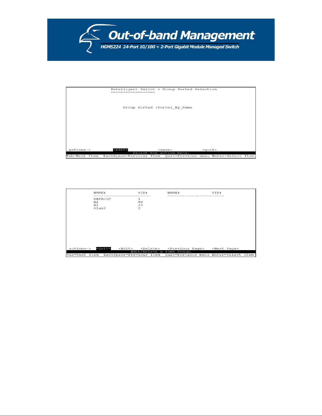
The Edit/Delete a VLAN group page will display the result.
Shown below is the page if sorted by name.
75
Page 76
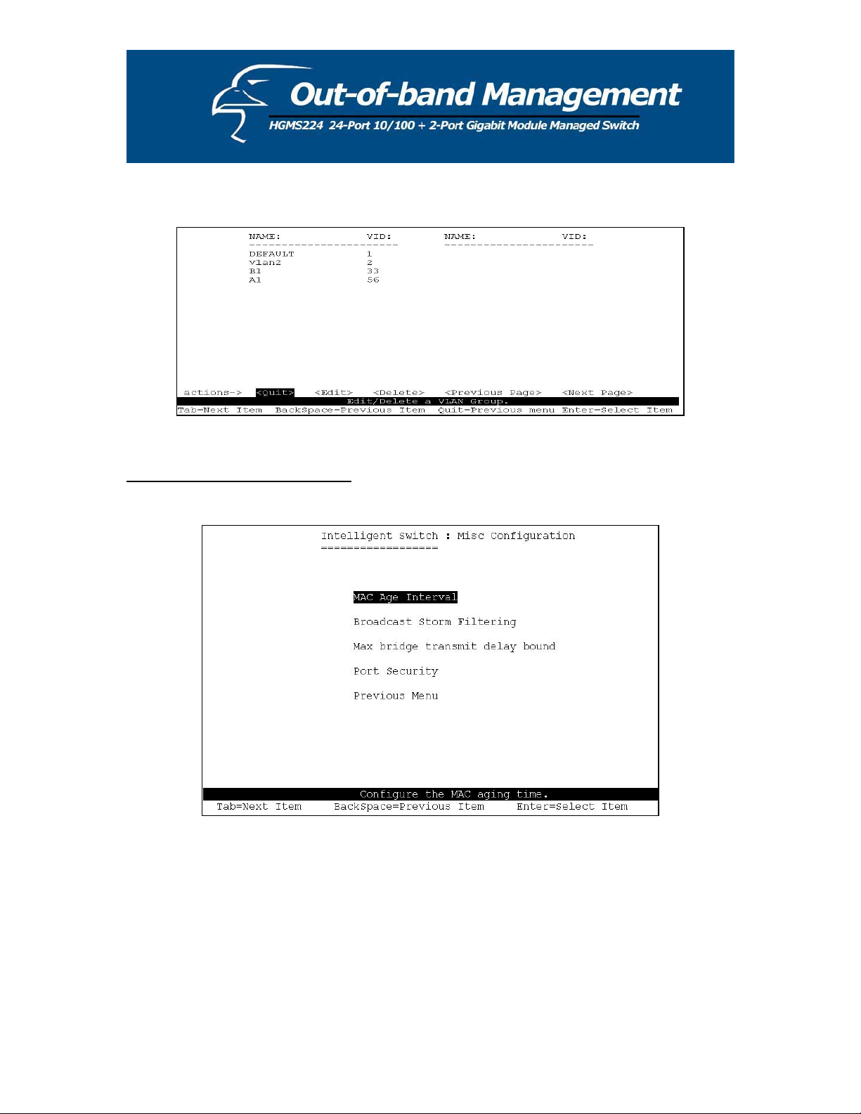
Shown below is the page if sorted by VID.
7.2.4 Miscellaneous Configuration
76
Page 77

7.2.4.1 MAC Age Interval
Type the number of seconds that an inactive MAC address remains in the switch’s address table.
he valid range is 300-765 seconds. The default value is 300 seconds.
T
77
Page 78

7.2.4.2 Broadcast Storm Filtering
This page will allow you to configure broadcast storm control.
1. Press <Edit> to configure the broadcast storm filter mode.
2
.PressSpacebar to choose the threshold value.
T
he valid threshold values are 5%, 10%, 15%, 20%, 25% and NO. The default value is 5%.
7.2.4.3 Max Bridge Transmit Delay Bound
1. Max bridge transmit delay bound: Limits the queuing time of the packets in the switch. If
enabled, the queued packets that exceed the limit will be dropped. Press Spacebar to set the
time. The valid values are 1sec, 2sec, 4sec and “Off”. The default setting is “Off”.
2. Low Queue Delay Bound: Limits the queuing time of the low priority packets in the switch.
If enabled, the low priority packets that exceed the “Low Queue Max Delay Time” will be
sent. Press Spacebar to enable or disable this function. The default setting is “Disabled”.
3. Low Queue Max Delay Time: Allows you to set the time that low priority packets can
queue in the switch. The valid range is 1-255ms. The default “Max Delay Time” is 255ms.
78
Page 79

NOTE: Make sure “Max bridge transit delay bound control” is enabled before enabling “Low
Queue Delay Bound” because “Low Queue Delay Bound” can only work when “Max bridge
tr
ansit delay bound control” is enabled.
7
.2.4.4 Port Security
A
port in security mode will be “locked” without permission of the address learning. Normally
only the incoming packets with SMAC already existing in the address table can be forwarded.
can disable the port from learning any new MAC addresses, then use the static MAC
You
resses screen to define a list of MAC addresses that can use the secure port.
add
79
Page 80

1. Select <Edit>.
.PressSpacebar to choose whether to enable or disable the item.
2
.PressCtrl + A to go back to the action menu.
3
. Select <Save> to save all configured values.
4
5. You can press <Next Page> to configure the remaining ports; you can press <Previous
Page> to return to the last page.
.2.4.5 Collision s Retry Forever
7
ollisions Retry Forever: Disable – In half-duplex, if collisions occur, the system will retry
C
48 times before dropping the frame.
Enable – In half-duplex, if collisions occur, the system will retry
forever (default).
80
Page 81

81
Page 82

7.2.5 Administration Configuration
82
Page 83

7.2.5.1 Change Username
From this page, you can change the web management username. Type in the new username, and
en press <Save>.
th
.2.5.2 Change Password
7
se this page; user can change web management login password.
U
83
Page 84

7.2.5.3 Device Information
From this page, you can configure the device information.
.2.5.4 IP Configuration
7
From this page, you can configure the IP settings
.
84
Page 85

uration7.2.6 Port Mirroring Config
Port mirroring is a method of monitoring traffic in switche
d networks. Traffic through ports can
be monitored via one designated port. Traffic through ports can be monitored by one specific
p
ort. That is, traffic going in or out of monitored ports will be duplicated into the monitoring port.
Press Spacebar to change the configuration of each item.
1. Select <Edit>.
2. Sniffer Mode: Press Spacebar to set the Sniffer mode to: Disable \Rx \Tx \Both.
. Monitoring Port: This means that the sniffer port can be used to see traffic of all monitored
3
ports. Press Spacebar to select it.
4. Monitored Ports: The ports you want to monitor. All monitored port traffic will be copied
to the sniffer port. You can select up to 25 ports to monitor on the switch. You can choose
which port to monitor in only one sniffer mode. Press Spacebar to choose a member port,
“V” – is the member, “—“ – not the member.
5. Press Ctrl + A go back to the action menu.
. Select <Save> to save all configured values.
6
. On the action menu line you can press <Next Page> to configure ports 9-26, and <Previous
7
Page> to return to the last page.
OTE: You can only operate in one sniffer mode at any given time.
N
85
Page 86

7.2.7 Priority Configuration
7.2.7
.1 Port Static Priority
he static priority is based on the port: if you set the port priority to high, incoming frames from
T
is port will always be high priority frames.
th
86
Page 87

7.2.7.2 802.1p Priority Configuration
ueues are assigned high/low priority levels from 0-7.
Q
. Select <Edit>.
1
2. Press Spacebar to select the priority level mapping to high or low queue.
3. High/Low Queue Service Ratio H/L: You can select the ratio of high priority packets and
low priority packets.
4. Press Ctrl + A to go back to the action menu.
5. Select <Save> to save all configured values.
87
Page 88

7.2.8 MAC Address Configuration
7.2.8.1 Static MAC Address
W
hen you add a static MAC address, it remains in the switch's address table, regardless of
w
hether the device is physically connected to the switch. This saves the switch from having to re-
le
arn a device's MAC address when the disconnected or powered-off device is active on the
network again. In this page, you can add/modify/delete a static MAC address.
88 88
Page 89

Add static MAC address
ʳ
ʳ
1. Press the <Add>, <Edit> keys to add static MAC addresses. ʳ
2. MAC Address: Enter the MAC address to and from which the port should
permanently forward traffic, regardless of the device’s network activity. ʳ
3. Port num: Press Spacebar to select the port number.
4. VLAN ID: If tag-based (802.1Q) VLANs are set up on the switch, static addresses
are associated with individual VLANs. Type the VID to associate with the MAC
address. ʳ
5. Press Ctrl + A to g
6. Then press <Save>
obacktotheactionmenu.
to save all configured values.
ʳ
89
Page 90

Edit Static MAC Addresses
1. Press the <Edit> key.
2. Choose the MAC address that you want to modify and then press enter.
ʳ
ʳ
ʳ
ʳ
ʳ
ʳ
ʳ
ʳ
ʳ
ʳ
ʳ
ʳ
ʳ
3.
Press the <Edit> key to modify all the items. ʳ
4. +Ato go back to the action menu, and then select <Save> to save all
Press Ctrl
configured values.
90
Page 91
Delete Static MAC Address
ʳ
1. Press <Delete> key to d
elete a filter MAC address. ʳ
2. Choose the MAC address that you want to delete and then press enter. ʳ
3. When pressing <Enter> once will complete deletion on delete mode.
91
Page 92
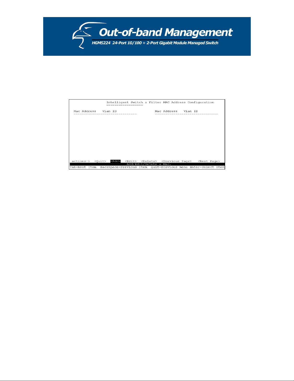
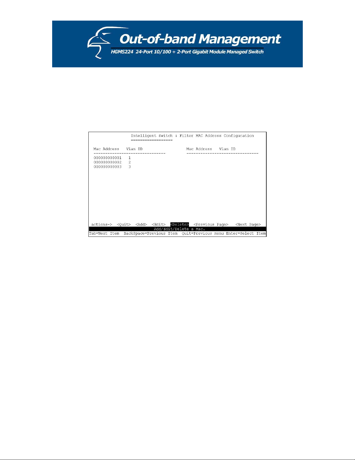
7.2.8.2 Filtering MAC Address
MAC ad . Traffic is filtered based on the
destinat s.
dress filtering allows the switch to drop unwanted traffic
ion addresses. In this page, you can add /modify /delete filter MAC addresse
Add filter MAC address
1. Press <Add>, <Edit> to add a filter MAC address.
2. MAC Address: Type the MAC address to filter.
3. VLAN ID: If tag-based (802.1Q) VLANs are set up on the switch, type the VID to
associate with the MAC address.
4. Press Ctrl + A to go back to the action menu, and then select <Save> to save all
configured values.
92
Page 93

ʳ
ʳ
ʳ
ʳ
ʳ
ʳ
ʳ
ʳ
ʳ
Edit filter MAC address ʳ
1. Press the <Edit> key.
2. Choose the MAC address that you want to modify and then press enter.
93
Page 94

ʳ
3. Press <Edit> to modify all the items. ʳ
4. Press Ctrl + A to go back to the action menu, and then select <Save> to save all
configured values.
ʳ
Delete filter MAC address
ʳ
ʳ
1. Press <Delete> to delete a filter MAC address. ʳ
2. Choose the MAC address that you want to delete and then press enter. ʳ
3. Pressing <Enter> once will complete the deletion.
94
Page 95

95
Page 96

.3 Protocol Related Configuration7
.3.1 Spanning-Tree Protocol7
The Spanning-Tree Protocol (STP) is a standardized method (IEEE 802.1D) for avoiding loops in
switched networks. When STP is enabled, it ensures that only one path at a time is active between
any two nodes on the network.
96
Page 97

7.3.1.1 Enabling STP
This page allows you to enable or disable the Spanning Tree function. Press Spacebar to select
Enabled” or “Disabled”.“
97
Page 98

7.3.1.2 STP System Configuration
1
. You can view the spanning tree information about the Root Bridge on the left.
2
. On the right, you can set new values for the STP parameters.
N
OTE: For parameter descriptions, please see Section 2-4-8.
98
Page 99

7.3.1.3 Per Port Configuration
1. PortState: Displays the spanning tree status for each port – whether the port is forwarding or
blocking.
2. Select <Edit>.
3
. PathCost: Specifies the path cost of the port that the switch uses to determine which ports
are the forwarding ports.
4. Priority: This specifies the priority of port; you can make it more or less likely to become the
root port.
5. Press Ctrl +A to go back to the action menu.
6. Select <Save> to save all configured values.
7. On the action menu line you can press <Next Page> to configure ports 9-26; press <Previous
Page> to return to the last page.
NOTE: For parameter descriptions, please see Section 2-4-8.
99
Page 100

7.3.2 SNMP
Any network management running the Simple Network Management Protocol (SNMP) can be
sed to manage the switch. Use this page to define management stations as trap managers and to
u
nter SNMP community strings. You can also define a name, location, and contact person for the
e
witch.
s
100 100
 Loading...