

Page 1
Hi-Gain™ Wireless-300N Wall Plug Multi-Function Extender HWREN25
website www.hawkingtech.com
e-mail techsupport@hawkingtech.com
© COPYRIGHT 2012 HAWKING TECHNOLOGIES,INC. ALL RIGHTS RESERVED.
USER’S MANUAL
Page 2

COPYRIGHT
Copyright ©2012 by Hawki ng Technologi es. All rights reserved. No part of
this public ation may be re produced, tran smitted, transc ribed, stored in a
retrieval system, or trans lated into any language or computer language, in
any form or by any means, electronic, me chanical, magnetic, optical,
chemical, manual or otherwise, without the prior written permission of this
company
Hawking Technologies makes no representations or warranties, either
expressed o r implied, with respect to the contents hereof and specifica lly
disclaims any warranties, merchantability or fitness for any partic ular
purpose. Any software described in this manual is sold or license d "as is".
Should the programs prove defective following their purchase, the buyer
(and not Hawking Technologies, its distributor, or its dealer) assumes the
entire cost of all necessary servicing, repair, and any incidental or
consequential damages re sulting from a ny defect in the software. Further,
this company reserves the right to revise this publication and to make
changes from time to time in the contents thereof without obligation to
notify any person of such r evision or cha nges.
Page 3

Federal Communication Commission
Interference Sta t ement
FCC Part 15
This equipment has been te sted and found to comply with the limits for a
Class B digital device, pur suant to Part 15 of FCC Rules. These limits are
designed to provide reasonable protection against harmful interfe rence in a
residential installation. This equipment generates, uses, an d can radiate radio
frequency energy and, if not installed and used in ac cordance with the
instructions, may cause ha rmful interfer ence to radio c ommunicatio ns.
However, there is no guarantee that interference will not occur in a particular
installation. If this equi pment does cause harmful interference to radio or
television reception, which can be determined by turning the equipment off
and on, the user is encoura ged to try to cor rect the interference by one or
more of the f ollowing measures:
1. Reorient or relocate the receiving antenna.
2. Increase the separation betw een the equip ment and receiver.
3. Connect the equipment into an outlet on a circ uit different from
that to whic h the receiver is connected.
4. Consult the dealer or an experienced radio tec hn ic ia n for he lp.
FCC Caution
This equipment must be in stalled and operated in accordance with pro vided
instructions and a minimum 20 cm spacing must be provid ed between
computer mounted antenna and person’s body (excluding extremities of
hands, wrist and feet) during wireless modes of operati on.
Page 4

This device complies with P art 15 of the FCC R ules. Operation is subject to
the following two conditions: (1) this device may not cause harmful
interfere nce, and (2) this d evice must acce pt any interference received,
including interference that may cause u ndesired operation.
Any changes or modifications not expressly approved by the party
responsible for compliance could void the authority to operate equipment.
Federal Communication Commission (FC C) Radiation Exp osure
Statement
This equipment complies with FCC radiation exposure set forth for an
uncontrolled environment. In order to avoid the possibility of exceeding the
FCC radio frequency exposure limits, human proximity to the antenna shall
not be less than 20cm (8 inc hes) during nor mal operation.
The antenna (s) used for this transmitter must not be co-located or operating
in conjunction with any other antenna or transmitter.
Page 5

R&TTE Compliance Statement
This equipment complies with all the requirements of DI RECTIVE
1999/5/EC OF THE EUROPEAN PARLIAMENT AND THE COUNCIL of
March 9, 1999 on radio equipment and telecommunication terminal
Equipment and the mutual r ecognition of their conformity (R&TTE).
The R&TTE Directive repeals and replaces in the directive 98/13/EEC
(Telecommunications Terminal Equipment and S atellite Earth Station
Equipment) A s of April 8, 2000.
Safety
This equipment is designed with the utmost care for the safety of those who
install and use it. However, special attenti on must be paid to the dangers of
electric shock and static e lectricity when working with electrical equ ipment.
All guidelines of this and of the computer manufacture must therefor e be
allowed at a ll times to ensure the safe use of the equipment.
EU Countries Intended for Use
The ETSI version of this de vice is intende d for home and office use in
Austria, Belgium, D enmark, Finland, France, Germany, Greece, Ireland,
Italy, Luxembourg, t he Netherlands, Portugal, Spain, Sweden, and the
United Kingdom.
Page 6

The ETSI version of this de vice is also aut horized for use in EFTA mem ber
states: Iceland, Liecht enstein, Norway, and Switzerland.
EU Countries Not intended for use
None.
Table of Contents
Chapter I: Product Information ...................................................................... 1
1-1 Introduction and safety information ................................................................ 1
1-2 Safety Information ........................................................................................... 4
1-3 System Requirements ....................................................................................... 5
1-4 Package Contents ............................................................................................ 6
1-5 Product Overview ............................................................................................ 7
CHAPTER II: Repeater Mode ...................................................................... 10
2-1 Repeater Quick Installation Guide ................................................................ 10
2-1-1 Hardware WPS button setup .............................................................. 12
2-2 Repeater Quick Setup .................................................................................... 15
2-3 General Setup ................................................................................................ 20
2-3-1 System ................................................................................................ 20
2-3-2 Local Network .................................................................................... 22
2-3-3 Wireless Network ............................................................................... 27
3-3-3-1 Basic Wireless Settings ........................................................... 28
3-3-3-2 Advanced Wireless Settings .................................................... 30
3-3-3-3 Security Settings ..................................................................... 33
3-3-3-4 Wireless Access Control ......................................................... 39
3-3-3-5 Wi-Fi Protected Setup (WPS) ................................................. 42
2-4 Status ............................................................................................................. 45
2-5 Configuration Tools ....................................................................................... 48
2-6 Firmware Upgrade ......................................................................................... 50
2-7 System Reset.................................................................................................. 52
CHAPTER III: Bridge Mode ...................................................................... 53
Page 7

3-1 Bridge Quick Installation Guide .................................................................... 53
3-1-1 Hardware WPS button setup .............................................................. 55
3-2 Bridge Mode Quick Setup ............................................................................. 58
3-3 General Setup ................................................................................................ 62
3-3-1 System ................................................................................................ 62
3-3-2 Local Network .................................................................................... 64
3-3-3 Wireless Network ............................................................................... 68
3-3-3-1 Basic Wireless Settings ........................................................... 69
3-3-3-2 Advanced Wireless Settings .................................................... 71
3-3-3-3 Security Settings ..................................................................... 74
3-3-3-4 Wireless Access Control ......................................................... 80
3-3-3-5 Wi-Fi Protected Setup (WPS) ................................................. 83
3-4 Status ............................................................................................................. 86
3-5 Configuration Tools ....................................................................................... 89
3-6 Firmware Upgrade ......................................................................................... 91
3-7 System Reset.................................................................................................. 93
CHAPTER IV: Access Point Mode ............................................................ 94
4-1 AP mode Quick Installation Guide ................................................................ 94
4-1-1 Hardware WPS button setup .............................................................. 95
4-2 Access Mode Quick Setup ............................................................................. 97
4-3 General Setup .............................................................................................. 102
4-3-1 System .............................................................................................. 103
4-3-2 Local Network .................................................................................. 106
4-3-3 Wireless Network ............................................................................. 110
4-3-3-1 Basic Wireless Settings ......................................................... 111
4-3-3-2 Advanced Wireless Settings .................................................. 114
4-3-3-3 Security Settings ................................................................... 117
4-3-3-4 Wireless Access Control ....................................................... 123
4-3-3-5 Wi-Fi Protected Setup (WPS) ............................................... 126
4-3-3-6 Security Tips for Wireless Network ...................................... 129
4-4 Status ........................................................................................................... 133
4-5 Configuration Tools ..................................................................................... 136
4-6 Firmware Upgrade ....................................................................................... 138
4-7 System Reset................................................................................................ 140
Chapter V: Appendix ................................................................................. 141
Page 8

5-1 Configuring TCP/IP on PC .......................................................................... 141
5-1-1 Windows XP IP address setup .......................................................... 141
5-1-2 Windows Vista/7 IP address setup .................................................... 143
5-1-3 Mac OS X IP Address Setup ............................................................ 145
5-2 Specification ................................................................................................ 146
5-3 Glossary ....................................................................................................... 147
Page 9

Chapter I: Produ ct Inf or m ati on
1-1 Introduction and safety information
Thank you for purchasing the HWREN25 Hi-Gain™ Wireless-300N Wall
Plug Multi-Function HWREN25!
The ultra-c ompact design and built-in power ada p ter allows you to install
this HWREN25 everywhere, and still provide excellent network
performance to extend the Wi-Fi signal and wireless coverage.
Other features of this Multi-Function HWREN25:
Extend the w ireless signal inside your home or offic e.
Ultra-com pact design while maintaining excellent network
performance.
LED signal indicator to easily recognize the best location
placement to extend W ir eless signal an d s ec ure be tte r wireless
performance.
The device supports Repeater mode, Access Point mode and
Bridge mode
Hardware switch button lets user change opera tio n m ode s
without logging into web firmware.
WPS (Wi-Fi Protected Setup) hardware button for easy
installation and secure wireless security.
1
Page 10
1-2 Definition of Su p po rte d Mod e s
Modes
The HWREN25 supports 3 different modes.
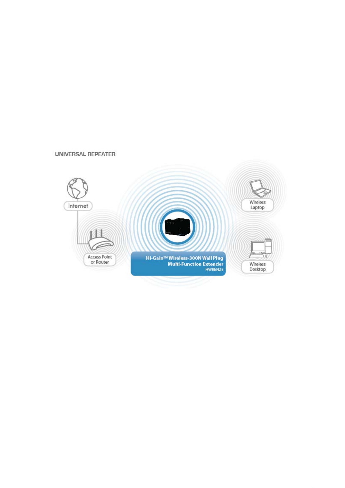
Repeater: Also known as range extender, this mode will allow you to repeat a
selected wireless signal so you can extend the coverage of the existing wireless
network. After setup, the device is standalone. Computers or other networked
devices can also be wired into the network port on the unit.
Bridge Mode: The HWREN25 will allow you to connect wired devices wirelessly to
an existing wireless router or access point. It will “bridge” these devices wirelessly
with your network. It will not broadcast any Wireless signal. It will only make a
wireless connection between the Access Point and the HWREN25 and allow devices
that are only wired to connect to the wireless network.
2
Page 11
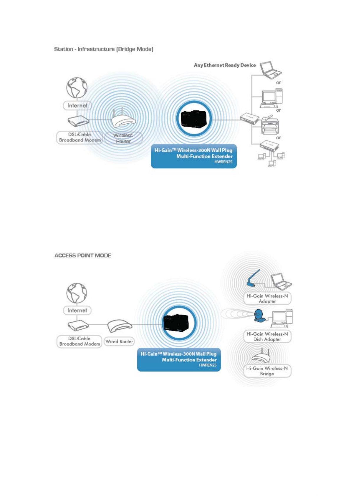
Access Point: The HWREN25 will broadcast a Wireless signal for other computers
and devices to connect to. Must be plugged into the router or network after setup.
3
Page 12

1-3 Safety Information
In order to keep the safety of users and property, please follow the
following safety instruction s :
1. This wireless HWREN25 is designed for indoor use only. DO NOT
expose this device to direct sun ligh t, rain, or snow.
2. DO NOT put this at or near hot or hum id places, like kitchen or
bathroom. Also, do not leave this Wireless HWREN25 in the car in
summer.
3. Do not allow children to put any parts of this wireless HWREN25 in
their mouths. It could cause serious injury or could be fatal. If they
throw this wireless HWREN25, it will be damaged. PLEASE KEEP
THIS WIRELESS HWREN25 OUT OF THE REACH OF CHILDREN!
4. This Wireless HWREN25 will become hot when being used for long
time (This is normal and is not a malfunction). DO NOT put the
Wireless HWREN25 on paper, cloth, or other flammable objects.
5. There’s no user-serviceable part inside the Wireless HWREN25. If you
find that the Wireless HWREN25 is not working properly, please contact
your place of purchase and ask for help. DO NOT disassemble the
Wireless HWREN25 by yourself, warranty will be vo id.
6. If the Wireless HWREN25 falls into water, DO NOT USE IT. Please
contact your place of purch ase and ask for help or for Warranty Return.
4
Page 13

1-4 System Requirements
Computer or network device(s) with wired or wireless network
interface card.
Web browser (Microsoft Interne t Ex plo rer 4.0 or above, Ne tscape
Navigator 4.7 or above, Opera web browser, Mozilla Firefox web
browser or Safari w eb browser).
An available AC power socket (100 – 240 V, 50/60Hz)
5
Page 14

1-5 Package Contents
Before you start to use this Wireless HWREN25, please check i f there’s
anything missing in the package. If so, please contact your place of
purchase to claim missing item s:
1x - Hi-Gain™ Wireless-300N Wall Plug Multi-Function HWREN25
1x - Quick Installation Guide
1x - Etherne t cord
1x – CD containing user manual and product registration.
6
Page 15
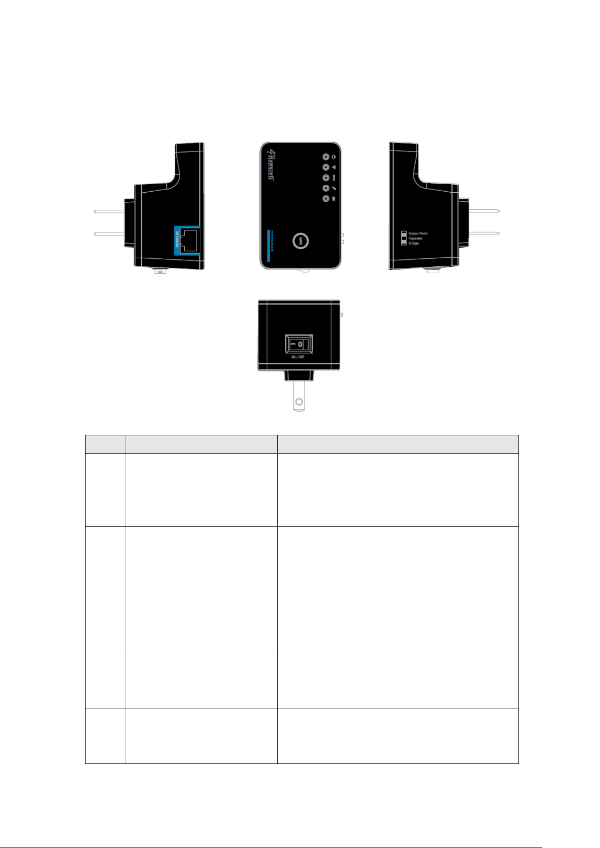
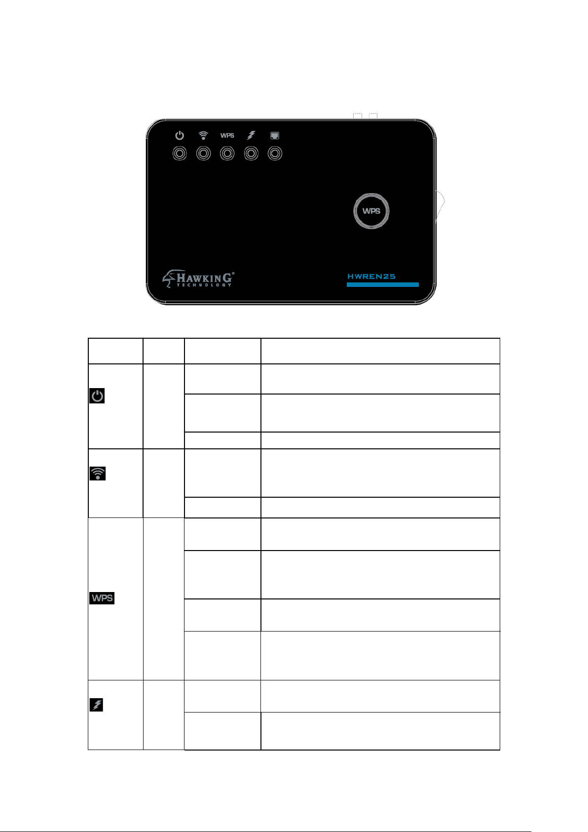
1-6 Product Overvie w
Item
Item Name
Description
A
Network
10/100M Ethernet LAN Port with
network sharing.
B
Reset / WPS
Reset the HWREN25 to factory default
WPS functio n.
C
Access
Switch the button to chang e operating
HWREN25 or Bridge mode.
D
ON/OFF
This is power on/off sw itch. If you want
to Off mode.
Interface Descriptions
A
B
C
D
Auto-MDI/MDI-X. Connecting to
computer, switch or hub for local
Point/HWREN25/Bridge
settings (clear all settings) or start WPS
function. Pr ess this button and hold for
10 seconds to restor e a ll se ttin g s to
factory defaults. For WPS, press this
button for less than 5 seconds to start
mode to Acces s Point or Range
to switch off th e HWREN25, switc h it
7
Page 16
Power is turned on.
Ready for “Reset to fact ory default”,
Off
Power is turned off.
Connected to wireless network. Wireless
receiving data)
Wireless network is not connected or on.
When WP S conne ct i on is suc ce ssf u l, turn
on for 5 minutes.
WPS is in progress of waiting for WPS
on, 0.1 second off) for 2 minutes.
Quick
Blinking
WPS error, blinking (0.1 second on, 0.1
second off )
NO WPS is in progress/ LED off mode
Excellent signal reception (signal strength
100%~67%).
Good signal reception
LED Definitions
LED Color LED Status Description
Power
Wireless
WPS
Green
Green
Green
Steady ON
Slow
Blinking
Blinking
Off
Steady ON
Blinking
Off
power LED is blinking.
function is act ive (transferring or
device’s connection, blinking (0.2 second
Steady ON
Signal
Amber
Blinking
Quick Blinking (66%~33%)
8
Page 17

Poor signal r eception
Slow blink ing (<33%)
Off
No Signal
Steady ON
LAN port is c onnected.
LAN port is active (transferring or
receiving data)
LAN port is not conne cte d
Green
Blinking
LAN
Off
9
Page 18

CHAPTER II: Repeater Mode
The HWREN25 is designed with the wireless repeater mode. This mode
allows you to repeat your wireless signal and coverage a nd help you to
solve wireless dead zones.
This chapter will show you how to quickly install this device by using
quick setup and define the settings on the web based interface.
2-1 Repeater Quick Installation Guide
For first time setup and easy installation, you can move t h is dev ice close
to the Wireless Broadband R outer or Access point you wish to c onnect to.
After the installation is done and wire les s co nne c tio n is made, you can
move this HWREN25 to the place you wish to use.
On the Top of the product, change the Switch mode se lec tor to
‘Repeater’.
Insert this device into a power outlet in the wall, and sw i tc h the W ireless
HWREN25’s power switch to ‘ON’. You should see ‘Power’ LED light
up in a few seconds. If not, please che ck if the power outlet you’re using
is working.
There are tw o ways to set this up:
You can build wireless connecti on via ‘Hardware WPS button’ or
‘Software web br ow s er’.
If your wireless router or access point supports ‘WPS’ , we recommend
you use the WPS button to establish connection. It is the fast and secure
10
Page 19

way without computer.
Using WPS button - please go to sectio n 2-1-1
Using Web browser - please go to sect io n 2-2
11
Page 20
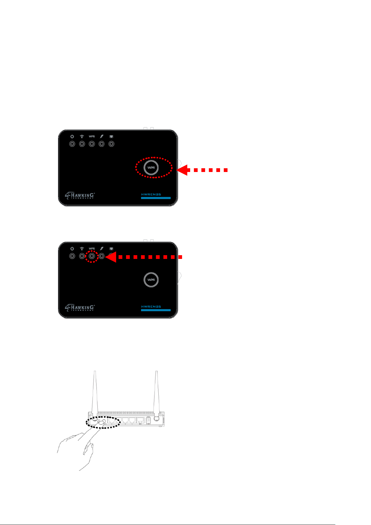
2-1-1 Hardware WPS button setup
WPS LED
WPS button
(1) Press and hold WPS button on HWREN25 for 2 seconds, ‘WPS’ LED
will start flashi ng.
(2) Press WPS button on the wireless br oa d ban d rou ter or acc e ss po int
you wish to connect within 2 minutes.
12
Page 21
WPS LED
Signal LED
NOTE: this WPS button position on access point is an example.
Different devices may have different WPS button position.
TIP: If the access point you wish to connect does not have hardware WPS button,
you can also use its web configuration menu’s WPS function to establish
connection. You can also login to this HWREN25’s web UI and do the setup
there. (Refer to 2-1-2)
(3) If W PS connection is successfully established, ‘WPS’ LED will light
for 5 minute s; if ‘WPS’ LED flashes f ast, there’s something wrong.
Please wait for 2 minutes until ‘WPS’ LED off , and try from step 1 again.
When WPS installation is successful, ‘WLAN” LED will turn on.
13
Page 22

(4) Please move the W ir eless HWREN25 to the place you wish to use it
(the best plac e would be a m idpoint between your router and your
wireless de vices so the HWREN25 can relay the signal).
You can check the ‘Signal’ LED status to understand signal reception
level.
Steady light: Excellent, signal > 67%
Quick Flash: Good, signal < 66%
Slow Flash: Fair, signal < 33%
No Flash: no signal.
NOTE: If the Signal LED is off, i t means the location is out of range of
your wireless broadband router or access point. Please move this
HWREN25 closer to the broadband router until the HWREN2 5 can
receive signal from broadband router and repeat its signal.
14
Page 23
2-2 Repeater Quick Setup
Before you c an connect to t he HWREN25 and start configuration
procedures, your computer must be able to get an IP address
automatically (use dynamic IP address). If it’s set to use a static IP
address, please refer to ‘Cha pte r V: Appendix, 5-1 Configuring TCP/IP
on PC’ to set your compute r to use dynamic IP addr ess.
(1)Use Ethe rnet cable to connect your computer’s Ethernet port an d
wireless HWREN25’s Ethern et port.
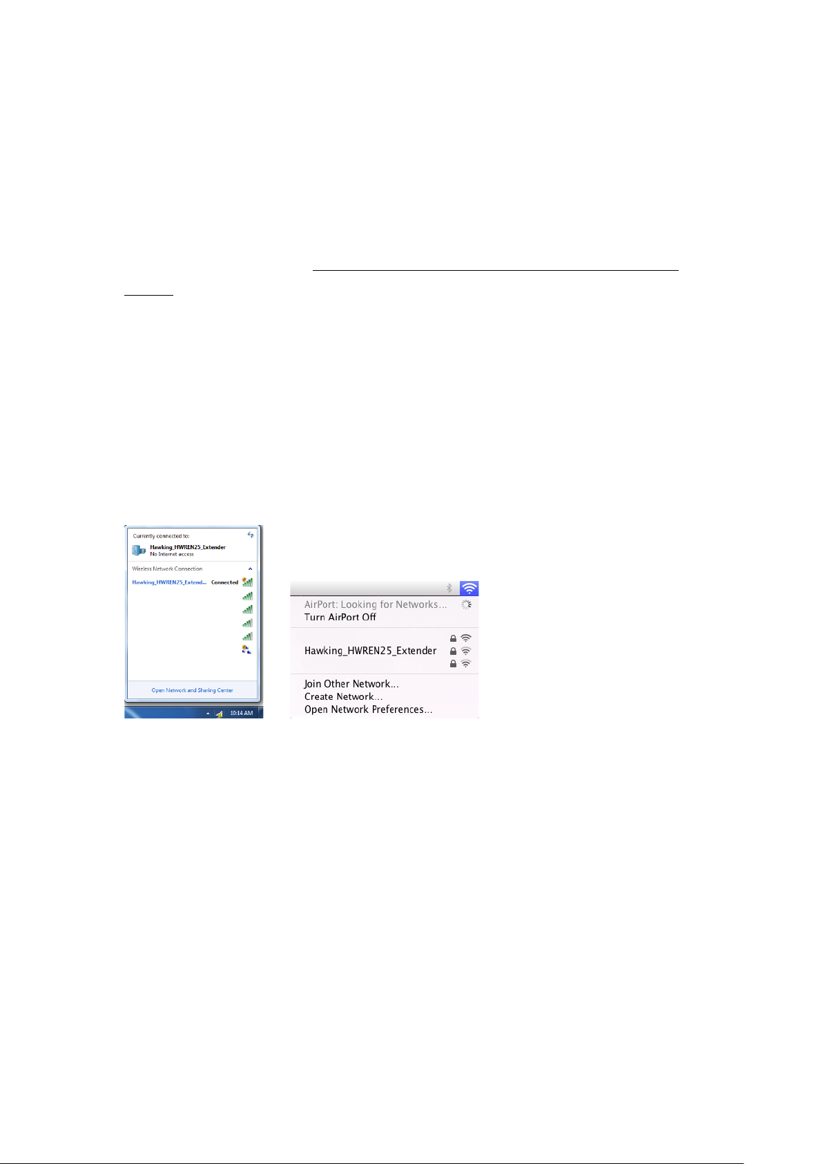
Or use your c omputer’s wireless configuration utility to search for a
wireless network called ‘Hawking_HWREN25_Extender’ and get
connected. (The default wire less name of this HWREN25 device is:
‘Hawking_HWREN25_Extender’)
(2) Open we b browser and input ‘http:// 192.168.1.240’ in addre ss bar. A
window will prompt you to input username and password. Default
username is ‘admin’ and password is ‘1234’. Click ‘OK’ button to
continue.
15
Page 24
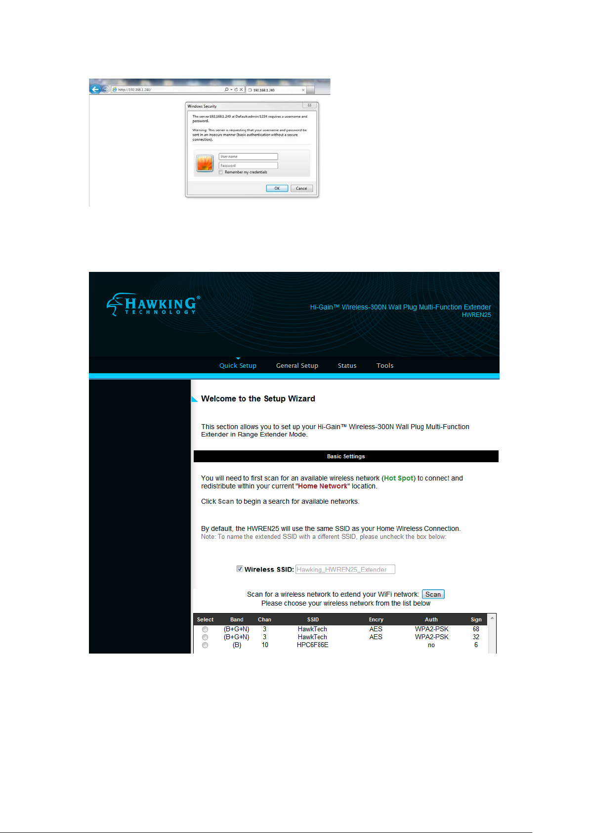
(3) Once y ou are logged in, the HWREN25 setup page will appear.
4) By default, the HWREN25 will use the same Wireless Name as the
network you are trying to ex tend. However, if you want to use your
own unique name to identify the HWREN25, you can u ncheck this box
and type in your own name.
16
Page 25
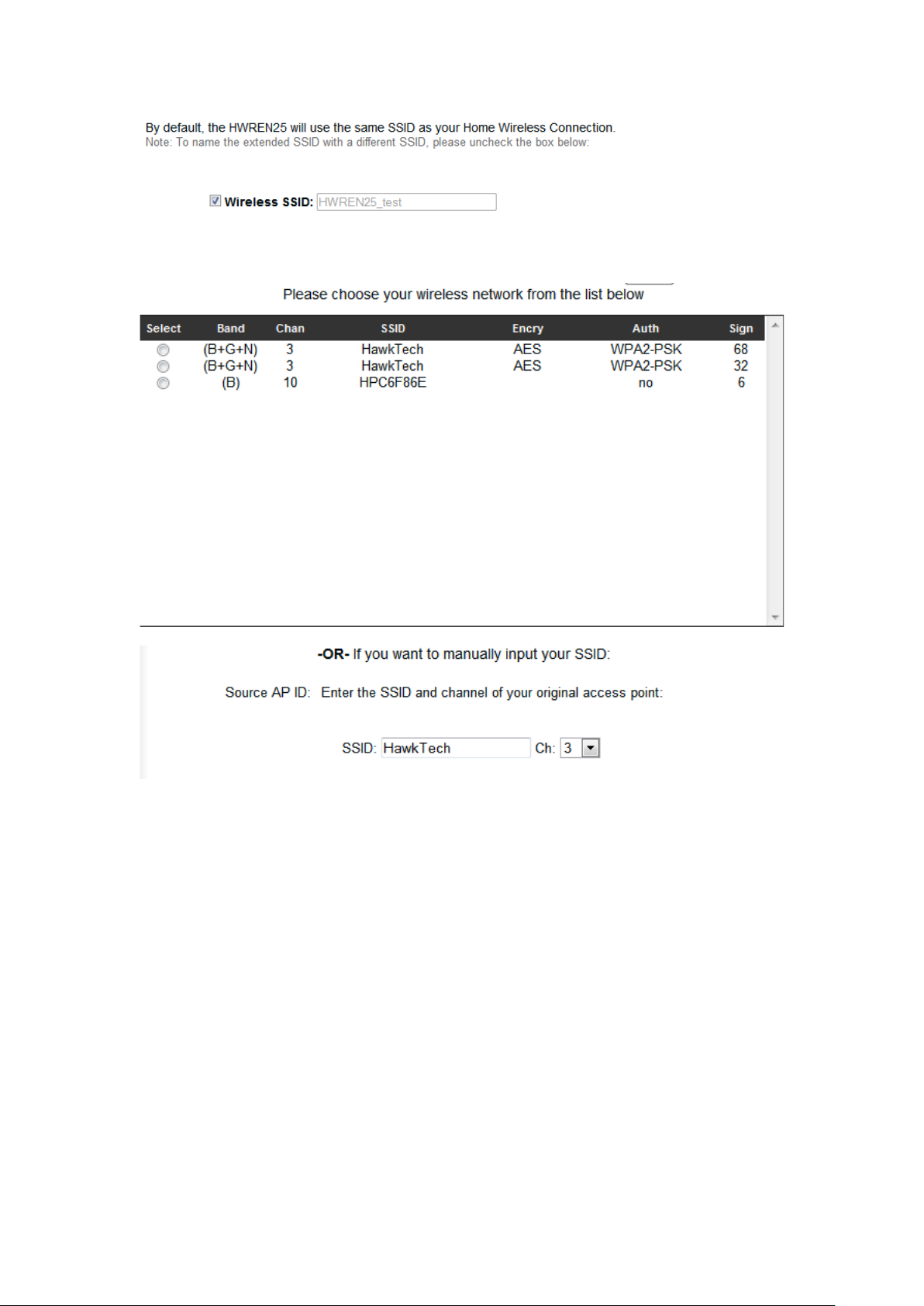
5) The wireless ne tworks availa ble in your area will appear in this
window
Please sele ct your network that you wish to r epeat. You may also
manually enter in your wire less network’s SSID and channel.
(6) Advanced IP address settings: This section allows you to set an IP
Address and subnet mask to fit your network if needed. Uncheck the
box to input. Otherwise, the default IP Address is 192.168.1.240
Note: It is re commended you give it an IP address in the same range of
your network. Otherwise, once it is configured it will not be in the same
range and y ou will not be ab le to access the setup page to view th e
general settings.
17
Page 26
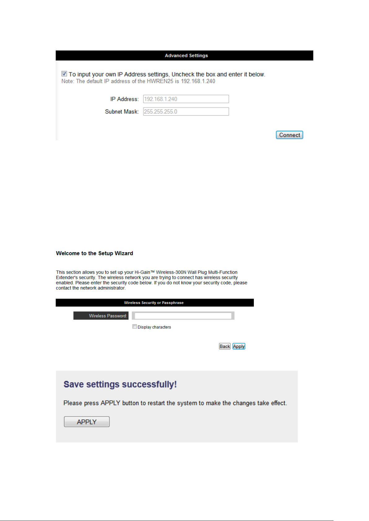
7) Click “Connect”
8) If your wireless network you hope to extend has wireless secuirty, the
next page will prompt you to enter in your secur ity key. Please make
sure you type in the exact key as the wireless network. If you are unsure
what your key is, please contact the wireless router/access point’s
manufacturer or your network adminsi trator. Click Apply when you’re
done.
18
Page 27

(8) After reboot is complete, you can close the web browser to finish this
quick setup. The HWREN25 will now be in extender mode. Please
place the extender in an op timal location.
19
Page 28

2-3 General Setup
In this chapter, you’ll know how to change the major settings of the
HWREN25. Log onto the device and click on ‘Ge neral Setup’.
2-3-1 System
Change password
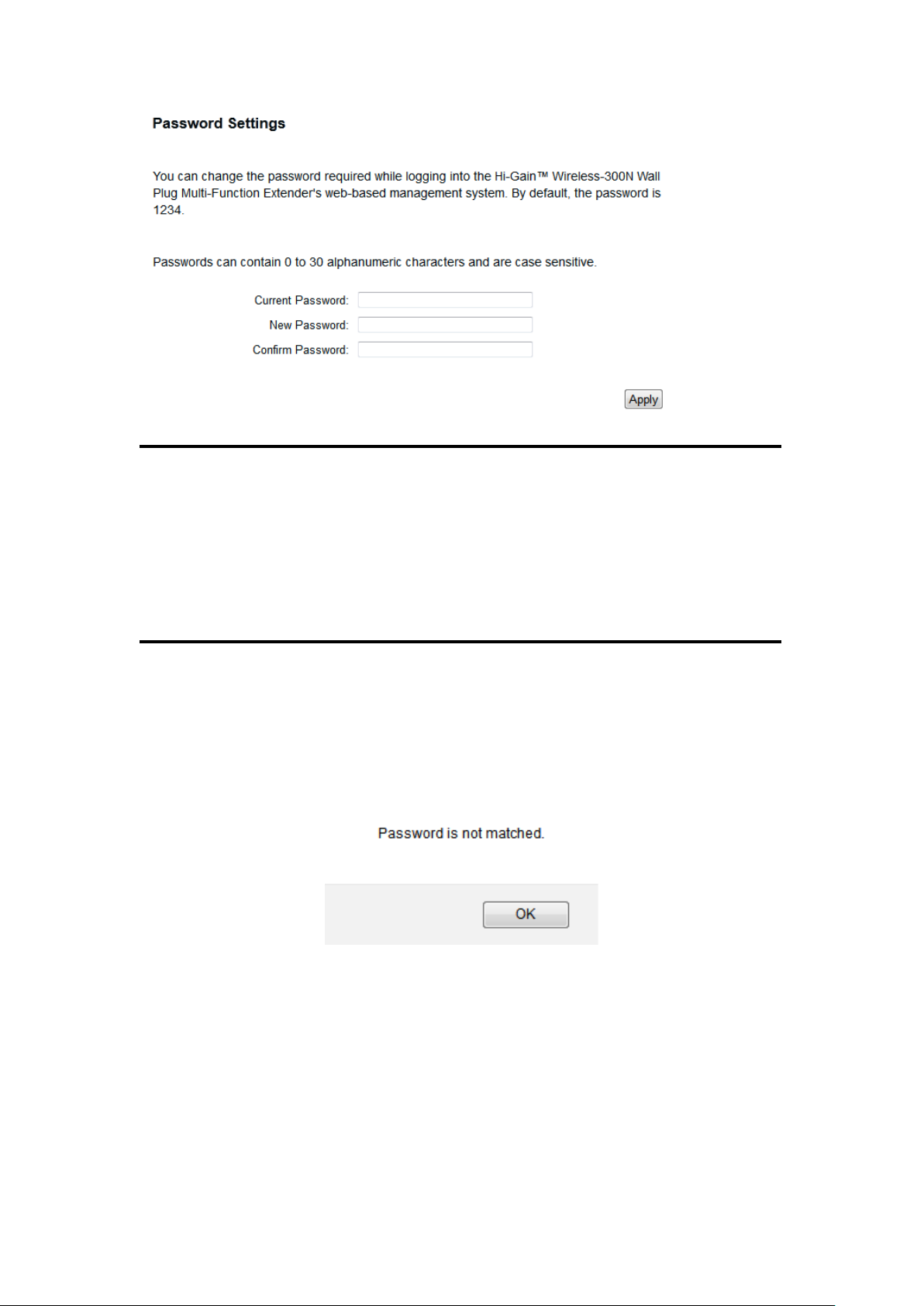
Default pas sword of the HWREN25 is ‘1234’ , and it’s displayed on the
login prompt when accessed from the web browser. There’s a security
risk if you don’t change the default password, since everyone can see it at
the prompt. Thi s is very important when you have wireless function
enabled.
To change p assword, please follow the instructions:
Please clic k ‘General Setup’ at top of w eb management interface, se lect
‘System’ tab on the left hand column, and then click ‘P assword Settings’,
and the following message will be displayed on your web browser:
20
Page 29
1
2
3
Current Please input current password here.
Password (1):
New Password (2): Please input new password here.
Confirm Please input new password her e again.
Password (3):
If the passw ord you typed in ‘New Passwor d’ (2) and ‘Confirm Password’
(3) field are not the same , you’ll see the following message:
Please retype the new password again when you see above message.
If you see the following m essage:
21
Page 30
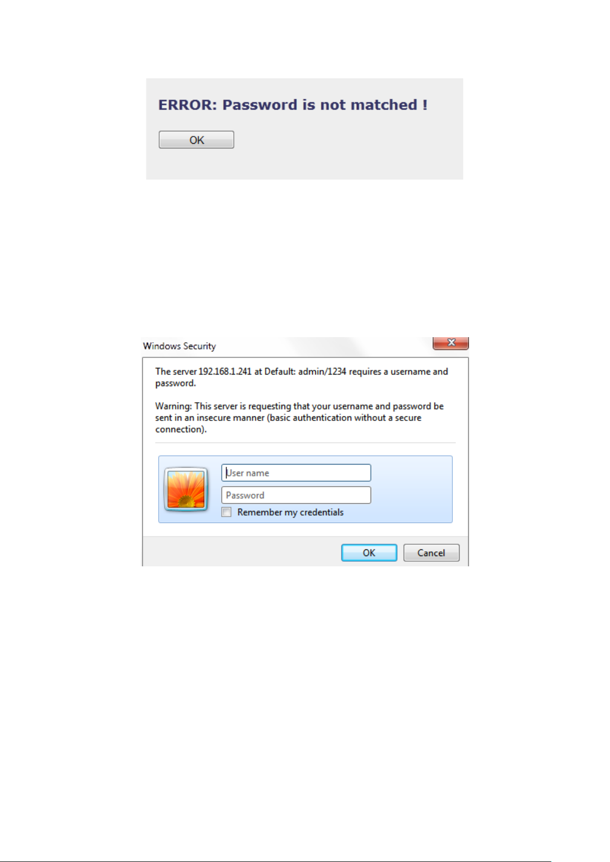
It means the c ontent in ‘Cur rent Password’ field is wron g, please click
‘OK’ to go back to previous menu, and try to input curren t password
again.
If the current and new passw ords are correctly entered, a fter you click
‘Apply’, you’ll be prompted to input your new password:
Please use ne w password to enter web management interface again, and
you should be able to login w ith new passw ord.
2-3-2 Local Net work
Before all computers using wired Etherne t connection ( i.e. those
computers con nec te d to th i s ac cess point’s LAN port 1 to 5 by Ethernet
cable) can communicate with each other and access Inter net, they must
have a valid IP address.
There are tw o ways to assign IP ad dresses to computers: static IP address
22
Page 31

(set the IP address for every computer manually), and dynamic IP addr ess
(IP address of computers will be assigned by acce ss point automatically.
It’s recommended for most computers to use dynamic IP address, it will
save a lot of time on setting IP addresses for every computer, especially
when there are a lot of computers in your netw ork; for servers and
network devices which will provide services to other computers and users
that come from the Internet, a static IP address should be used.
23
Page 32

Suggestions on IP Address numbering plan:
1
3
2
4
If you have no idea on how to define an IP address plan for your
network, here are some suggestions.
1. A valid IP address has 4 fields: a.b.c.d, for most of home and
company users, it’s suggested to use 192.168.c.d, where c is
an integer between 0 and 254, and d is an integer between 1
and 254. This router is capable to work with up to 253 clients,
so you can set ‘d’ field of IP address of router as 1 or 254 (or
any number bet ween 1 and 254) , and p ic k a n um ber between 0
and 254 for field ‘c’.
2. In most cases, y ou should use ‘ 255. 255.2 55.0’ as subnet mask,
which allows up to 253 clients (this also meets router’s
capability of working with up to 253 clients).
3. For all servers and network devices which will provide
services to other people (like Internet service, print service,
and file service), they should use static IP address. Give each
of them a unique number between 1 and 253, and maintain a
list, so everyone can locate those servers easily.
4. For computers which are not dedicated to provide specific
service to others, they should use dynamic IP address.
Please clic k ‘General Setup’ at the to p of web management interface and
click ‘Local Network’ on the left hand co lumn.
There are two setup groups here: ‘LAN IP’ and ‘DHCP Server’
IP address (1): Please input the IP add ress of this access point.
Subnet Mask (2): P lea se in pu t subn et m ask fo r th is net wo rk .
Gateway Add ress (3): Please input your gateway address for the
network.
DHCP Server (4): If you want to activate DHC P server func tion of this
access point, se le c t ‘E nabl e d’, or se t it t o
24
Page 33

‘Disabled’.
Recommended Value if you don’t know what to fill:
IP Address: 192.168.1.241 DNS Server: (leave it blank)
Subnet Mask: 255.255.255.0 DHCP Server: Disabled
Gateway Address: (leave it blank)
25
Page 34

1
3 4 2 5 6
These settings are only a vailable when ‘DHCP Se rver’ in ‘LAN IP’
section is ‘Enabled’.
Lease Time (1): Please choose a lease time (the dur ation that
every computer can keep a specific IP address) of
every IP add ress assi gne d by th is access point fr om
dropdown menu.
DHCP C lient Start IP (2): Please i nput the start IP address of the IP
range.
DHCP C lient End IP (3):Please input the end IP address of the IP range.
DHCP C lient Gateway (4) : Please input your default gateway address
DHCP Client DNS (5): Please input your DNS server address
Domain Name (6): If you wish, you can also optionally input the
domain name for your network. This is optional.
Recommended Value if you don’t know what to fill:
Lease Time: Two Weeks (or ‘Forever’, if you have less than 20 computers)
Default Gateway: (leave it blank)
Domain Server IP: (leave it blank)
Start IP: 192.168.1.100
End IP: 192.168.1.200
Domain Name: (leave it blank)
26
Page 35

NOTE:
1. The number of the last field (mentioned ‘d’ field) of ‘End IP’ must be
greater than ‘Start IP’, and cannot be the same as router’s IP address.
2. The former three fields of IP address of ‘Start IP’, ‘End IP’, and ‘IP
Address of ‘LAN IP’ section (mentioned ‘a’, ‘b’, and ‘c’ field) should be the same.
3. These settings will affect wireless clients too.
2-3-3 Wireles s Network
Please clic k ‘General Setup’ tab at the top of web management interface,
and then click ‘Wireless Configuration’ tab on the left hand col umn. The
following message will be displayed on y our web browser:
27
Page 36

3-3-3-1 Basic Wire less Settings
2
3
4
5
6
7
Please clic k ‘General Setup’ menu at the top of web management
interface, then click ‘Wireless Configuration’ on the left ha nd column.
Choose ‘Basic Settings’.
The HWREN25 will allow you connect wired devices wirelessly to an existing
wireless router or access point. It will “bridge” these devices wirelessly with your
network. It will not broadcast any WiFi signal. It will only make a wireless
connection between the Access Point and the HWREN25.
Band (2): Select the band you want to use. These should match the
settings of your wireless network you are attempting to
bridge.
SSID (3): This is the name of wireless network that the HWREN25 will
broadcast.
Channel (4): This is the wireless channel that the HWREN25 will
broadcast at. Please make sure it is the same channel of
the existing network you hope to repeat.
28
Page 37

Associated Clients (5): This button will show what wireless devices are currently
connected to the HWREN25.
Root AP SSID (6): The network you are trying to repeat.
Select Wireless Network (7): Selecting this will allow you to choose a wireless
network to extend. Select your network and click close.
Click scan if your network does not appear.
After you finish these wir eless settings, please click ‘Apply’ button,
button, and the following message will be displayed on your web
browser:
Please clic k ‘Go Back’ to go back to previ ous setup menu; to continue on
access poin t setup, or click ‘Apply’ to reboot the access point so the
settings will take effect. Please wait 30-60 seconds for the access point to
reboot.
NOTE: If you don’t have special reason to limit the type of allowed
wireless clients, it’s recommended to choose ‘2.4 GHz (B+G+N) to
maximize wireless cli ent comp ati bi lit y.
29
Page 38

3-3-3-2 Advance d Wi reless Settings
1
2
3
4
5
7
8
6
9
10
11
12
This bridge provi des some advanced control of wireless param eters, if
you want to configure these settings, please click ‘Ge neral Setup’ at the
top of web management interface and clic k ‘Wireless Configuration’ on
the left han d column. Choose “Advanced Se ttings’.
Fragment Threshold(1): Set the Fragme nt t hreshold of w i reless radio.
Do not modify the default value if you do not
understand the function, default value is ‘2346’.
RTS Threshold(2): Set the RTS threshold of wireless radio. Do not
modify the de fault value if you do not understand
the function, default val ue is ‘2347’.
Beacon Interval(3): Set the beacon interval of wireless ra dio. Do not
modify the de fault value if you do not understand
30
Page 39

the function, default val ue is ‘100’.
DTIM Period(4): Set the DTIM peri od of wireless radio. Do n ot
modify the
the function
default value if you do
, default value is ‘3’.
not understand
Data Rate(5): Set the wireless d ata transfer rate to a certain value.
Since most of wireless devices will negotiate with
each other and pick a proper data transfer rate
automatically. It is not necessary to change this
value unless you know what w ill happen after
modification.
N Data Rate(6): Same as above, but o nly f or 80 2.11n clients.
Channel Width(7): Set channel width of wireless radio. Do not modify
the default value if you do not understan d the
function, de fault setting is ‘Auto 20/40 MHz’.
Preamble Type(8): Set the type of pre amble , do not modify the default
value if you do not know wh at it is, de f au lt set t ing
is ‘Short Preamble’.
Broadcast ESSID(9): Decide if the wirele ss access point will
broadcast its own ESSID or not. You can hide the
ESSID of your wireless access point (set the option
to ‘Disable’), so only those people who kno w the
ESSID of you r wireless access point can connect to
the unit.
CTS Protect(10): Enabling this sett i ng wil l reduce the cha nc e of rad io
signal collisi o ns be tw e en 80 2.11b and 802.11g/n
wireless access points. It is recommen ded to set this
option to ‘Auto’ or ‘Always’. However, if you set to
‘None’, your wireless access point should be a ble to
function properly.
Transmit Power(11): You can set the output power of wireless radio.
31
Page 40

Unless you are using this wireless acce ss p oi nt i n a
large open space, you may not have to set output
power to 100%. Th i s wil l enh anc e sec u r ity
(malicious / unauthorize d users in distance will
not be able to reach you r wi re les s acc e ss point).
WMM(12): Wi-Fi MultiMedia (WMM) will enhance the data
transfer pe rformance of mu ltimedia contents when
they are being transferred over a wireless n etwork.
If you do not understand the function, the n it is
safe to set th is option to ‘Enable’, however, default
value is ‘Disable’.
After you finish these wir eless settings, please click ‘Apply’ button,
button, and the following message will be displayed on your web
browser:
Please clic k ‘Go Back’ to go back to previ ous setup menu; to continue on
access point setup, or click ‘Apply’ to reboot the access point so the
settings will take effect. Please wait 30-60 seconds for the access point to
reboot.
32
Page 41

3-3-3-3 Security Settings
It is important to set your wireless security settings properly! In bridge
mode, the security settings must match the wirele ss network you are
planning to connect to, otherwise, a connection cannot be established.
To set wire less security settings, please click ‘Gene ral Setup’ tab at the
top of web management interface, then click ‘Wireless Config uration’ on
the left han d column. Choose ‘Security Settings’.
Please sele ct an encryption method from the ‘Encryption’ dropdown
menu, there a re four optio ns:
Disable
WEP
WPA
WPA Radius
Disable wir e le ss se c urity
When you select this mode, data e ncryption is dis abled.
Use this option only when th ere is no secu rity set up on the original
Wireless Signal.
WEP - Wired Equivalent Privacy
When you select this mode, the wireless a ccess point will use WEP
encryption, and the followin g set u p m enu will be sh ow n on y our web
browser:
33
Page 42

2
3
7
8
9 6 10
4
5
Key Length (2): There ar e two types of WEP key length: 64-bit and
128-bit. Using ‘128-bit’ is safer than ’64-bit’, but
will reduce some data trans fer pe rf ormance.
Key Format ( 3): There are two types of key format: ASCII and Hex.
When you sele ct a key format, the number of
characters of key will be displayed. For ex ample, if
you select ’64-bit’ as key lengt h, and ‘Hex’ as key
format, you’ll see the me ssage at the right of ‘K ey
Format’ is ‘Hex (10 characters), which means the length of
WEP key is 10 characters.
Default Tx Key (4): This device only su p po r ts one WE P Key ‘Key 1’.
Encryptio n Key (5) Input WEP key characters here, t he number of
characters mu st be th e same as the numbe r
displayed at ‘Key Format’ field. You can use any
alphanumerical characters (0-9, a-z, and A-Z) if you
select ‘ASCII’ key format, and if you select ‘H ex’ as
key format, you can use characters 0-9, a-f, and A-F.
You must enter at least one encryption key here, and
if you entered multiple WEP keys, they should not be
34
Page 43

same with each other.
Enable 802.1x IEEE 802.1x is an authentication protocol. Every
Authentication (6): user must use a valid account to login to this
wireless access point before accessing the wireless
LAN. The aut hentication i s proce ssed by a RADIUS
server. This mode only authenticates user by IEEE
802.1x, but it does no t encryption the data dur ing
communica tion. If there is a RADI US server in you
environment, ple ase enable this function. Check this
box and another sub-menu will appear:
RADIUS Server Please input the IP address of RADIUS server here.
IP address (7):
RADIUS Server Please input the port number of RADIUS server
here.
Port (8):
RADIUS Server Please input the password here.
Password (9):
TIPS: Examples of WEP key
ASCII (5 characters): pilot phone 23561 2Hyux #@xmL
ASCII (13 characters): digitalFAMILY 82Jh26xHy3m&n
Hex (10 characters): 287d2aa732 1152dabc85
Hex (26 characters): 9284bcda8427c9e036f7abcd84
To i mprove security level, do not use words that can be found in a dictionary or are
easy to remember! Wireless clients will automatically remember the WEP key, so you
only have to input the WEP key on wireless client once, and it is suggested that to use a
complex WEP key to improve security level. Once you have chosen a password, write
it down and keep it in a secure place.
After you finish WEP setting, please click ‘Apply’ (10) button and the
following message will be dis played on your web browser:
35
Page 44

2
3
5
4
Please clic k ‘Go Back’ to go back to previ ous setup menu, or click
‘Apply’ to reboot the access point so the se tt ing s wil l take effect. Please
wait 30-60 seconds for the acce ss point to reb oot.
Wi-Fi Protected Access (WPA):
When you select this mode, the wireless a ccess point will use WPA
encryption, and the following setup menu will be shown on your web
browser:
WPA U nicast Please select a type o f WPA cipher suite.
Cipher Suite ( 2): Available options are: WPA (TKIP), WPA2
(AES), and WPA2 Mixed. You can select one of them,
but you have to make sure your wireless client
support the cip her yo u sele c te d.
Pre-shared Select the type of pre-shared key, you
Key Format ( 3) : can select Passphrase (8 or more alphanumerical
characters, up to 63), or Hex (64 characters of 0-9,
and a-f).
Pre-shared Please input the WPA passphrase here.
Key (4): It’s not recommended to use a word that can
be found in a diction ary du e to security reason.
After you finish WPA Pre-shared ke y setting, please click ‘Apply’ button
36
Page 45

(5) and the following me ssage will be displayed on your web browser:
would be needed for those clients to use WPA and WPA2 encryption.
3
4 2 5
6
Please clic k ‘Go Back’ to go back to previ ous setup menu, or click
‘Apply’ to reboot the acces s po in t so the se tt in gs wil l take effect. Please
wait 30-60 seconds for the acce ss point to reb oot.
NOTE: Some wireless clients (especially those manufactured before
year 2003) only support WEP or WPA (TKIP) cipher. A driver upgrade
WPA RADIUS:
If you have a R ADIUS server, this ac cess point can work with it and
provide safer wireless authentication.
WPA U nicast Please select a type o f WPA cipher suite.
Cipher Suite: Available options are: WPA (TKIP), WPA2
(AES), and WPA2 Mixed. You can select one of them,
but you have to make sure your wireless client
support the cip her yo u sele c te d.
RADIUS Server Please input the IP addre ss of your
IP address (3): Radius authentication server here.
37
Page 46

RADIUS Server Please input the port number of your
Port (4): Radius authentication server here.
Default setti ng is 18 1 2.
RADIUS Server Please input the password of your Radius
Password (5): authentication server here.
After you finish with all settings, please click ‘Apply’ (6) button and the
following message will be displayed on y our web browser:
Please clic k ‘Go Back’ to go back to previ ous setup menu, or click
‘Apply’ to reboot the access point so the se ttin g s wil l take e ffect. Please
wait 30-60 seconds for the acce ss point to reb oot.
38
Page 47

3-3-3-4 Wire less Acc ess Control
1
2
3
6 7 8
4
This functi on will help you prevent unaut horized users f rom connecting
to your wireless access point; only those wireless devices who have a
MAC address you assigned can gain access to your wireless access point.
Use this function with oth er security measures describe d in previous
section, to create a safer wireless environment.
You can add up to 20 M AC addresses by using this funct ion. Please click
‘General Setup’ at the top of web management interface and click
‘Wireless Configuration’ on the left hand c olumn. Select ‘Access
Control’.
All allowed MAC addresses w ill be displayed in ‘MAC Addres s Filtering
Table.
Enable Wireless To enforce MAC addr ess filtering, you have to check
39
Page 48

Access Control (1): ‘Enable Wireless Access Control’ . When this item is
unchecked, wireless access point will not enforce
MAC address filte ring of wireless clie nts.
MAC Address (2): Input the MAC address of your wireless devices here,
dash ( - ) or colon ( : ) are not required. (i.e. If the
MAC address label of your wireless devic e indicates
‘aa-bb-cc-dd-ee-ff’ or ‘aa:bb:cc:dd:e e: f f’, just input
‘aabbccddeeff’.
Comment (3): You can input any text here as the comment of this
MAC address, like ‘ROOM 2A Computer’ or
anything. You can input up to 16
alphanumerical
characters he re. This is optio na l and you can leave
it blank, how ever, it’s recommended to use this fie ld
to write a comment for every MAC addresses as a
memory aid.
Add (4): Click ‘Apply’ button to add the MAC address
and associated comment to the MAC address
filtering table.
Clear (5): Click ‘Clear’ to remove the value you inputted
in MAC address and comment field.
Delete Selected (6): If you want to delete a specific MAC ad dress
entry, check the ‘select’ box of the MAC address you
want to delete, the n clic k ‘Dele te Sel ec te d’ button.
(You can select more than one MAC addresses).
Delete All (7): If you want to delete all MAC a ddresse s listed
here, please click ‘Delete All’ button.
After you finish with all settings, please click ‘Apply’ (8) button and the
following message will be displayed on your web browser:
40
Page 49

Please clic k ‘Go Back’ to go back to previ ous setup menu, or click
‘Apply’ to reboot the access point so the se tt ing s wil l take effect. Please
wait 30-60 seconds for the acce ss point to reb oot.
41
Page 50

3-3-3-5 Wi-Fi Protected Setup (WPS)
Wi-Fi Protected Setup (WPS) is the simplest way to build conne ction
between wir eless network clients and th is wireless access point. You
don’t ha ve to select an e ncryption mode and input a long encryption
passphrase every time whe n you need to set up a wireless client, you only
have to press a button on the wireless client and this wireless access point,
and the WPS will automatically configure for you.
This wireless ac ce ss po i nt su ppor t s two ty pes of WPS: Push-Button
Configuration (PBC), and PIN code. If you w ant to use PBC, you have to
push a specif ic button on the wireless client to start WPS mode, and
switch this wireless access point to WPS mode too. You can push
Reset/WPS button of this wireless acces s point, or click ‘Start PBC’
button in the web configuration interfac e to do this; if you want to use
PIN code, you have to know th e PIN code of wireless client and switch it
to WPS mode, then provide the PIN code of the wireless client you wish
to connect to this wir e le ss acc es s poin t. The detailed instructio ns are
listed follow:
Please clic k ‘General Setup’ at the to p of web management interface and
click ‘Wireless Configuration’ on the left h and column. Select ‘WPS’.
42
Page 51

1 3 4 2 5
Enable WPS (1) Check this box to enable WPS function, uncheck
it to disable WPS.
WPS Information (2) WPS Status: If the wireless sec urity (encryption)
function of this wireless access point is properly set,
you’ll see ‘Configured’ message here. If wireless
security func tio n ha s no t been set, you’ll see ‘Not
configured’.
Self PIN cod e: This is the WP S PIN code of this
wireless access point. This code is useful when you
need to build wireless connection by WPS with
other WPS-enabled wireless devices.
SSID: The SSID of this w ireless acc ess point will be
displayed here.
Authentication Mode: The wireless security
43
Page 52

authentica t ion mo de of th i s wireless acce s s poi n t
will be disp layed here. If you do no t enable securit y
function of the wireless acces s point before WPS is
activated, th e acc es s po int will auto set the security
to WPA (AES) and generate a set passphrase key for
WPS connection.
Passphrase Key: The wireless security key of the
access point wi ll be dis played here .
Config Mode (3) There are ‘Registrar’ and ‘Enrollee’ modes for the
WPS connection. When ‘Reg istrar’ is enabled, the
wireless clients will follow the a ccess point’s
wireless settings for WPS conne ction. When
‘Enrolle’ mode is enabled, the access point will
follow the wireless sett in gs of wi reless clie nt fo r
WPS connection.
Configure Click ‘St art PBC’ to start Push-Button style WPS
by Push Button (4) setup procedure. This wireless access point will wait
for WPS requests from wireless clients for 2 minutes.
The ‘WLAN’ LED light on the wirele ss ac c ess p oi nt
will be steady for 2 minutes when this wireless
access point is waiting for incoming WPS reque st.
Input client Please input the PIN code of the wireless client you
PinCode (5) wish to connect, and click ‘Start PIN’ button.
The ‘WLAN’ LED light on the wi reless acce ss p oint
will be steady when this wireless access point is
waiting for incoming WPS request.
44
Page 53

2-4 Status
The status and information of the HWREN25 will be displayed here.
Click on the status tab on the top of web page.
You should see the screen looks li ke this ( the con te nt s will va ry
depending o n your current firmware):
On the right hand column und er status, click “Local Network”
45
Page 54

Wireless Network Configurati on: This sec tion describe s the current
wireless settings of the HWREN25.
Mode: Curre nt mode
ESSSID: The broadcast name of the HWREN25
Channel: Cu rrent Wireless C hannel
Security: The type of security the HWREN25 is using.
Local Network Configuration: This se ction descri bes the current network
settings of the HW RE N 25
IP Address: Current I P address
Subnet Mask : Current subnet mask
DHCP Server: current status of th e DHCP, enabled or d isabled
Mac A d dre s s: the Mac address of the HWRE N 25
On the right hand column, click Active DHCP Client
46
Page 55

The Active DHCP Client describes clients tha t are current c onnected and
receiving an IP address from the HWREN25. Only enabl ed if DHCP
Server is enabled in the local network settings.
On the right hand column, click on Statisti cs
This section describes the amount of data sent/r e cei ve on bot h th e wir ed
and wireles s connections.
47
Page 56

2-5 Configurati on Tools
1 2 3
You can back up all configurations of this access point to a fil e, so you
can make se veral cops of the HWREN25’s configuration for security
reason.
To backup or restore the HWREN25’s configuration, please follow the
instructions:
Please clic k ‘Tools’ menu at the top of web managem ent interface, and
then click ‘ Configuration Tools’ on the left hand column.
Backup Press ‘Save...’ button, and y ou’ll be prom pt e d to
Settings (1): download the configuration as a file, default
filename is ‘de fau lt. bi n’, you c an ple ase sa ve it as
another filename for different v ersions, and keep it
in a safe place.
Restore Press ‘Browse …’ to pick a previously-saved
Settings (2): configuration file from your computer, and then
click ‘Upload’ to transfer the configuration file to
48
Page 57

access point. After the configuration is uploaded,
the access p oint’s configuration will be replaced by
the file you just uploaded.
Restore to Click this butt on to remove all se tt i ng s you m ade,
and
Factory Default (3): rest ore the configuratio n of this access point back to
factory defau lt se tt in gs.
49
Page 58

2-6 Firmware Upgrade
The system software used by this access point is known as ‘firmware’,
just like any applications on your com puter, when you replace the old
application with a new one; your computer will be equipped with new
function. You can also use this firmware upgrade function to add new
functions to your access p oint, even fix the bugs of this access point.
To upgrade firmware, please follow the instructions:
Please clic k ‘Tools’ menu at the top of web managem ent interface, and
then click ‘ Firmware Upgra de’ on the lef t hand column.
Click ‘Next’ button if you w i sh to up gra de your firmware.
50
Page 59

Click ‘Browse’ button, and you’ll be prompted to prov ide the filename of
the firmw are upgrade file. Please downl oad the latest fir mware file fr om
the Hawking Technol ogies website a t www.hawkingte ch.com, and use it
to upgrade your access point.
After a firmware upgrade file is se lected, click ‘Apply’ button, and the
access poin t will start firmware upgrade procedure aut omatically. The
procedure may take several minutes, please be patient.
NOTE: Never interrupt the upgrade procedure by closing the web
browser or physically disconnect your computer from router. If the
firmware you uploaded is corrupt, the firmware upgrade will fail, and
you may have to return this router to the dealer of purchase to ask for
help. Warranty is void if you interrupt the upgrade procedure.
51
Page 60

2-7 System Reset
If you think you network performance is bad, or you find the behavior of
the access point is str a nge , y ou can per f or m a access po i nt reset.
Sometimes it will solve the problem.
Please clic k ‘Tools’ menu at the top of web managem ent interface, and
then click ‘ Reset on the left hand colum n.
Please clic k ‘Apply’ to reset your access point, and it will be available
again after a few minutes, please be patient.
52
Page 61

CHAPTER III: Bridge Mode
Client mode can let your networking device have wireless capability; it
will become your device’s wireless network card. You can connect this
device to an Et hernet port on a TV or DVD player or game console
device with Ethernet cable.
This chapter will show you how to quickly install this device by using
quick setup and show you the e ach detailed setting on web UI page of
client mode.
3-1 Bridge Quick Installation Guide
Switch mode selector to ‘Bridge’.
Insert this device into power out let o n the wa ll, and sw i tc h wire le s s
HWREN25’s power switch to ‘ON’. You should see ‘Power’ LED light
up in few sec onds. If not, please check if the power outlet you’ re using is
working.
Connect your wired networking device(wired PC, or internet TV, or game
console..etc.) and this device by Ethernet cable.
NOTE: You must set your networking de vice as DHCP client (obtain IP
automatically from DHCP server)
You can build wireless connecti on via ‘Hardware WPS button’ or
‘Software web br ow s er’.
If your wireless router or access point supports ‘WPS’, we recommend
53
Page 62

you use the WPS button to establish conne ction. It is the fast and secure
way without computer.
Using WPS button - please go to sectio n 3-1-1
Using Web browser - please go to sect io n 3-2
54
Page 63

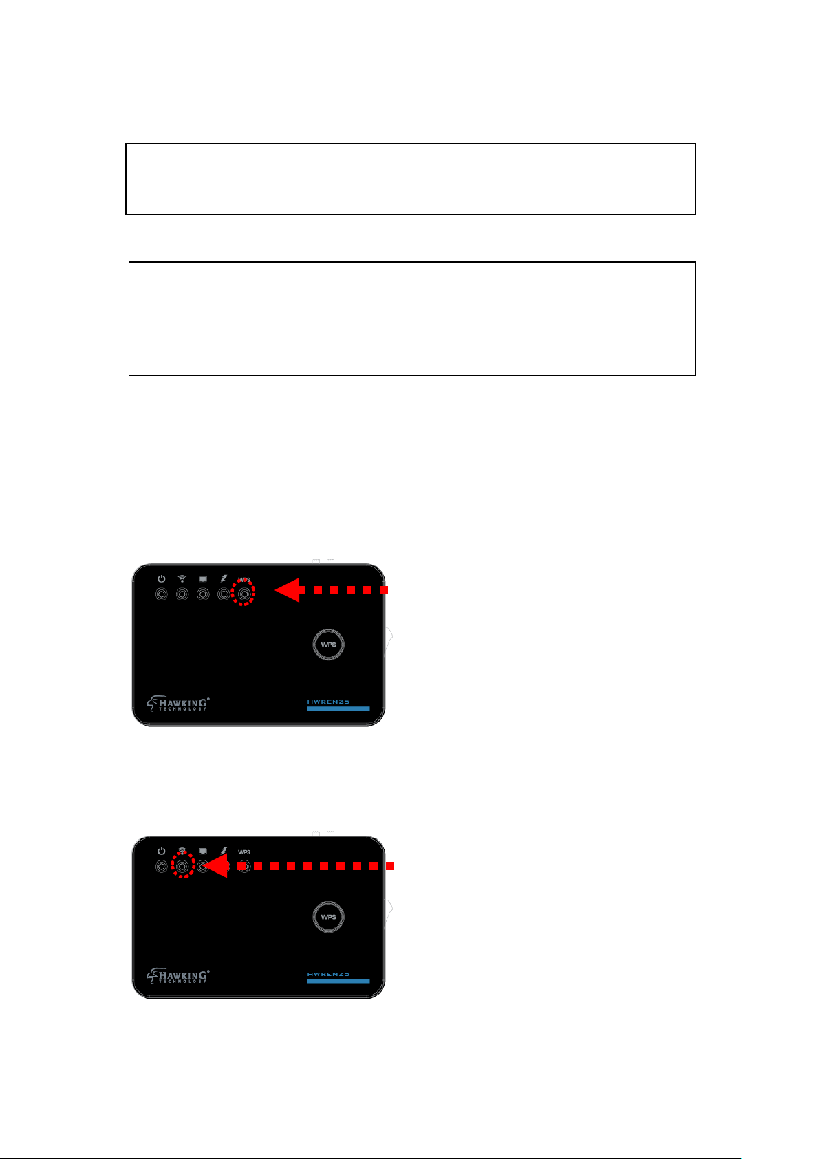
3-1-1 Hardware WPS button setup
WPS LED
WPS button
(1) Press an d hold WPS button on the HWREN25 for 2 seconds. The
‘WPS’ LED will start flashing.
(2) Press the WPS button on the wir eless broadband router or access
point you wish to connect w ithin 2 minutes.
55
Page 64

WPS LED
NOTE: Different devices will have different WPS button positions.
TIP: If the access point you wish to connect does not have hardware WPS button,
you can also use its web configuration menu’s WPS function to establish
connection. You can also log into the HWREN25’s web UI to do a quick setup.
(refer. to section 3-2)
(3) If W PS connection is successfully established, the ‘WPS’ LED will
light for 5 minutes; if the ‘ WPS’ LED flashes fast, there’s something
wrong. Please wait for 2 minutes until ‘WPS’ LED is off and try from
step 1 again.
When WPS installation is successful, ‘ WLAN” LED will turn on.
56
Page 65

Signal LED
You can check the ‘Signal’ LED status to understand signal reception
level.
Steady light: Excellent, signal > 67%
Quick Flash: Good, signal < 66%
Slow Flash: Fair, signal < 33%
No Flash: no signal.
NOTE: If the Signal LED is off, it means the location is out of range of
your wireless broadband router or access point. Please move this
HWREN25 closer to the wireless signal until the HWREN25 can
receive signal from broadband router and bridge the signal.
57
Page 66

3-2 Bridge Mode Quick S et up
Before you connect to the HWREN25 and start configuration procedures,
your computer must be able to get an IP address automatically (use
dynamic IP address). If it’s set to use static IP address, or you’re unsure,
please refer to ‘Chapter 5-1 Configuring TCP/IP on PC’ to set your
computer to use dynam ic IP address.
(1)Use an Ethernet cable to connect your computer’s Ethernet port and
HWREN25’s Ethernet port.
(2) Open we b browser and input ‘http:// 192.168.1. 241’ in addr ess bar. A
window will prompt you to input username and password. Default
username is ‘admin’ and password is ‘1234’. Click ‘OK’ button to
continue.
(3) Once y ou are logged in, the HWREN25 setup page will appear.
58
Page 67

4) Click on “Select Site Survey” to choose the wireless network you wish
to bridge to.
Select your network and click “Done”
The SSID fie ld should be filled in with the network nam e you selected.
(5) Advanced IP address settings: This section allows you to set an IP
Address and subnet mask to fit your network if needed. Uncheck the
box to input. Otherwise, the de fault IP Address is 192.168.1.241
Note: It is re commended you give it an IP address in the same range of
your network. Otherwise, once it is configured it will not be in the same
range and y ou will not be ab le to access the setup page to view the
general settings.
59
Page 68

6) After you ha ve selected your wireless network and clicked apply, if
your wirele ss network you h ope to bridge has wireless security, the next
page will prompt you to ent er in your secur ity key. Please make sure
you type in the exact key a s the wireless network. If you are unsure
what your key is, please contact the wireless router/access point’s
manufacturer or your network adminsi trator. Click Apply when you’re
done.
7) Click app ly for your setti ngs to take effect
60
Page 69

(8) After reb oot complete, you can close the web browser to finish this
quick setup. Connect the HWR EN25 via Ethernet cable to the devic e
you wish to bridge.
61
Page 70

3-3 General Setup
In this chapter, you’ll know how to change the major settings of the
HWREN25. Log onto the device and click on ‘Ge neral Setup’.
3-3-1 System
Change password
Default pas sword of the HWREN25 is ‘1234’ , and it’s displayed on the
login prompt when accessed from the web browser. There’s a security
risk if you don’t change the default password, sinc e everyone can see it at
the prompt. This is very important whe n you have wireless function
enabled.
To change p assword, please follow the instructions:
Please clic k ‘General Setup’ at top of w eb management interface, select
‘System’ tab on the left hand column, and then click ‘P assword Settings’,
and the following message will be displayed on your web browser:
62
Page 71

1
2
3
Current Please input current password here.
Password (1):
New Password (2): Please input new password here.
Confirm Please input new password her e again.
Password (3):
If the passw ord you typed in ‘New Passwor d’ (2) and ‘Confirm Password’
(3) field are not the same , you’ll see the following message:
Please retype the new password again when you see above message.
If you see the following m essage:
63
Page 72

It means the c ontent in ‘Cur rent Password’ field is wron g, please click
‘OK’ to go back to previous menu, and try to input curren t password
again.
If the current and new passwords are correctly entered, after you click
‘Apply’, you’ll be prompted to input your new password:
Please use ne w password to enter web management interface again, and
you should be able to login w ith new passw ord.
3-3-2 Local Net work
Before all computers using wired Ethernet connection (i.e. those
computers connected to this access point’s LAN port 1 to 5 by Ethernet
cable) can communicate with each other and access Inter net, they must
have a valid IP address.
64
Page 73

There are tw o ways to assign IP ad dresses to computers: static IP address
(set the IP address for every computer manually), and dynamic IP addr ess
(IP address of computers will be assigned by acce ss point automatically.
It’s recommended for most computers to use dynamic IP address, it will
save a lot of time on setting IP addresses for every computer, especially
when there ar e a lot of computers in your ne twork; for serve rs and
network devices which will provide services to other computers and users
that come from the Internet, a static IP a ddr e ss sho ul d be use d.
Suggestions on IP Address numbering plan:
If you have no idea on how to define an IP address plan for your
network, here are some suggestions.
5. A valid IP address has 4 fields: a.b.c.d, for most of home and
company users, it’s suggested to use 192.168.c.d, where c is
an integer between 0 and 254, and d is an integer between 1
and 254. This router is capable to work with up to 253 clients,
so you can set ‘d’ field of IP address of router as 1 or 254 (or
any number between 1 and 254), and pick a number between 0
and 254 for field ‘c’.
6. In most cases, y ou should use ‘ 255. 255.2 55.0’ as subnet mask,
which allows up to 253 clients (this also meets router’s
capability of working with up to 253 clients).
7. For all servers and network devices which will provide
services to other people (like Internet service, print service,
and file service), they should use static IP address. Give each
of them a unique number between 1 and 253, and maintain a
list, so everyone can locate those servers easily.
8. For computers which are not dedicated to provide specific
service to others, they should use dynamic IP address.
65
Page 74

Please clic k ‘General Setup’ at the to p of web management interface and
1
3
2
4
click ‘Local Network’ on the left hand co lumn.
There are two setup groups here: ‘LAN IP’ and ‘DHCP Server’
IP address (1): Please input the IP add ress of this access point.
Subnet Mask (2): Please input subnet mask for th is net w ork .
Gateway Add ress (3): Please input your gateway address for the
network.
DHCP Server (4): If you want to activate DHC P server func tion of this
access point, se le c t ‘E nabl e d’, or se t it t o
‘Disabled’.
Recommended Value if you don’t know what to fill:
IP Address: 192.168.1.241 DNS Server: (leave it blank)
Subnet Mask: 255.255.255.0 DHCP Server: Disabled
Gateway Address: (leave it blank)
66
Page 75

1
3 4 2 5 6
These settings are only a vailable when ‘DHCP Se rver’ in ‘LAN IP’
section is ‘Enabled’.
Lease Time (1): Please choose a lease time ( the d ur ati on th at
every computer can keep a specific IP addr ess) of
every IP add ress assi gne d by th is access point fr om
dropdown menu.
DHCP C lient Start IP (2): Please i nput the start IP address of the IP
range.
DHCP C lient End IP (3):Please input the end IP address of the IP range.
DHCP C lient Gateway (4) : Please input your default gateway address
DHCP Client DNS (5): Please input your DNS server address
Domain Name (6): If you wish, you can also optionally input the
domain name for your network. This is optional.
Recommended Value if you don’t know what to fill:
Lease Time: Two Weeks (or ‘Forever’, if you have less than 20 computers)
Default Gateway: (leave it blank)
Domain Server IP: (leave it blank)
Start IP: 192.168.1.100
End IP: 192.168.1.200
Domain Name: (leave it blank)
67
Page 76

NOTE:
1. The number of the last field (mentioned ‘d’ field) of ‘End IP’ must be
greater than ‘Start IP’, and can not be the same as router’s IP address.
2. The former three fields of IP address of ‘Start IP’, ‘End IP’, and ‘IP
Address of ‘LAN IP’ section (mentioned ‘a’, ‘b’, and ‘c’ field) should be the same.
3. These settings will affect wireless clients too.
3-3-3 Wireles s Network
Please clic k ‘General Setup’ tab at the top of web manage ment interface,
and then click ‘Wireless Configuration’ tab on the left hand column. The
following message will be displayed on y our web browser:
68
Page 77

3-3-3-1 Basic Wire less Settings
2
3
4
Please clic k ‘General Setup’ menu at the top of web management
interface, then click ‘Wireless Configuration’ on the left h and column.
Choose ‘Basic Settings’.
The HWREN25 will allow you connect wired devices wirelessly to an existing
wireless router or access point. It will “bridge” these devices wirelessly with your
network. It will not broadcast any WiFi signal. It will only make a wireless
connection between the Access Point and the HWREN25.
Band (2): Select the band you want to use. These should match the
settings of your wireless network you are attempting to
bridge.
SSID (3): This is the name of wireless network you are attempting to
connect to. Make sure it matches exactly with the wireless
network you are attempting to connect to.
Site Survey (4): This allows you to select a wireless network to bridge to.
‘Select Site Survey’ button, then a “Wireless Site Survey
Table” will pop up. It will list all available access points
nearby. Please select the wireless network and click “Done”
Click “Refresh” if you do not see your network.
69
Page 78

After you finish these wir eless settings, please click ‘Apply’ button,
button, and the following message will be displayed on your web
browser:
Please clic k ‘Go Back’ to go back to previ ous setup menu; to continue on
access point setup, or click ‘Apply’ to reboot the access point so the
settings will take effect. Please wait 30-60 seconds for the access point to
reboot.
70
Page 79

3-3-3-2 Advance d Wi reless Settings
1
2
3
4
5
7
8
6
9
10
11
12
This bridge provi des some advanced control of wireless param eters, if
you want to configure these settings, please click ‘Ge neral Setup’ at the
top of web management interface and clic k ‘Wireless Configuration’ on
the left han d column. Choose “Advanced Se ttings’.
Fragment Threshold(1): Set the Fragme nt t hreshold of w i reless radio.
Do not modify the default value if you do not
understand the function, default value is ‘2346’.
RTS Threshold(2): Set the RTS threshold of wireless radio. Do not
modify the de fault value if you do not understand
the function, default val ue is ‘2347’.
Beacon Interval(3): Set the beacon interval of wireless ra dio. Do not
modify the de fault value if you do not understand
71
Page 80

the function, default val ue is ‘100’.
DTIM Period(4): Set the DTIM peri od of wireless radio. Do n ot
modify the
the function
default value if you do
, default value is ‘3’.
not understand
Data Rate(5): Set the wireless data tra nsfer rate to a ce rtain value.
Since most of wireless devices will negotiate with
each other and pick a proper data transfer rate
automatically. It is not necessary to change this
value unless you know what w ill happen after
modification.
N Data Rate(6): Same as above, but o nly f or 80 2.11n clients.
Channel Width(7): Set channel width of wireless radio. Do not modify
the default value if you do not understan d the
function, de fault setting is ‘Auto 20/40 MHz’.
Preamble Type(8): Set the type of preamble, do not modify the default
value if you do not know wh at it is, de f au lt set t ing
is ‘Short Preamble’.
Broadcast ESSID(9): Decide if the wirele ss access point will
broadcast its own ESSID or not. You can hide the
ESSID of you r wireless access point (set the option
to ‘Disable’), so only those people who know the
ESSID of you r wireless access point can connect to
the unit.
CTS Protect(10): Enabling this sett i ng wil l reduce the cha nc e of rad io
signal collisi o ns be tw e en 80 2.11b and 802.11g/n
wireless access points. It is recommended to set this
option to ‘Auto’ or ‘Always’. However, if you set to
‘None’, your wireless access point should be a ble to
function properly.
Transmit Power(11): You can set the output power of wireless radio.
72
Page 81

Unless you a re using this wireless access p oi nt in a
large open space, you may not have to set output
power to 100%. Th i s wil l enh anc e sec u r ity
(malicious / unauthorize d users in distance will
not be able to reach you r wi re les s acc e ss point).
WMM(12): Wi-Fi MultiMedia (WMM) will enhance the data
transfer pe rformance of mu ltimedia contents when
they are being transferred over a wireless n etwork.
If you do not understand the function, the n it is
safe to set th is option to ‘Enable’, however, default
value is ‘Disable’.
After you finish these wir eless settings, please click ‘Apply’ button,
button, and the following message will be displayed on your web
browser:
Please clic k ‘Go Back’ to go back to previ ous setup menu; to continue on
access poin t setup, or click ‘Apply’ to reboot the access p oi nt so the
settings will take effect. Please wait 30-60 seconds for the access point to
reboot.
73
Page 82

3-3-3-3 Security Settings
It is important to set your wireless security settings properly! In bridge
mode, the security settings must match the wireless network you are
planning to connect to, otherwise, a connection cannot be established.
To set wire less security settings, please click ‘Gene ral Setup’ tab at the
top of web management interface, then click ‘Wireless Configuration’ on
the left hand column. Choose ‘Security Settings’.
Please sele ct an encryption method from the ‘Encryption’ dropdown
menu, there a re four optio ns:
Disable
WEP
WPA
WPA Radius
Disable wir e le ss se c urity
When you select this mode, data encryption is disabled.
Use this option only when th ere is no secu rity set up on the original
Wireless Signal.
WEP - Wired Equivalent Privacy
When you select this mode, the wireless a ccess point will use WEP
encryption, and th e f ollowing setup menu will be sh ow n o n your web
browser:
74
Page 83

2
3
7
8
9 6 10
4
5
Key Length (2): There ar e two types of WEP key length: 64-bit and
128-bit. Using ‘128-bit’ is safer than ’64-bit’, but
will reduce some d ata transfer pe rformance.
Key Format ( 3): There are two types of key format: ASCII and Hex.
When you sele ct a key format, the number of
characters of key will be displayed. For ex ample, if
you select ’64-bit’ as key lengt h, and ‘Hex’ as key
format, you’ll see the me ssage at the right of ‘Key
Format’ is ‘Hex (10 characters), which means the length of
WEP key is 10 characters.
Default Tx Key (4): This device only su p po r ts one WE P Key ‘Key 1’.
Encryptio n Key (5) Input WEP key characters here, the number of
characters mu st be th e same as the numbe r
displayed at ‘Key Format’ field. You can use any
alphanumerical characters (0-9, a-z, and A-Z) if you
select ‘ASCII’ key format, and if you select ‘H ex’ as
key format, you can use characte rs 0-9, a-f, and A-F.
You must enter at least one encryption key here, and
if you entered multiple WEP keys, they should not be
75
Page 84

same with each other.
Enable 802.1x IEEE 802.1x is an authentication protocol. Every
Authentication (6): user must use a valid account to login to this
wireless access point before accessing the wireless
LAN. The aut hentication i s proce ssed by a RADIUS
server. This mode only authenticates user by IEEE
802.1x, but it does no t encryption the data dur ing
communication. If there is a RADIUS server in you
environment, ple ase enable this function. Check this
box and another sub-menu will appear:
RADIUS Server Please input the IP address of RADIUS server here.
IP address (7):
RADIUS Server Please input the port number of RADIUS server
here.
Port (8):
RADIUS Server Please input the password here.
Password (9):
TIPS: Examples of WEP key
ASCII (5 characters): pilot phone 23561 2Hyux #@xmL
ASCII (13 characters): digitalFAMILY 82Jh26xHy3m&n
Hex (10 characters): 287d2aa732 1152dabc85
Hex (26 characters): 9284bcda8427c9e036f7abcd84
To i mprove security level, do not use words that can be found in a dictionary or are
easy to remember! Wireless clients will automatically remember the WEP key, so you
only have to input the WEP key on wireless client once, and it is suggested that to use a
complex WEP key to improve security level. Once you have chosen a password, write
it down and keep it in a secure place.
After you finish WEP setting, please click ‘Apply’ (10) button and the
following message will be displayed on y our web browser:
76
Page 85

2
3
5
4
Please clic k ‘Go Back’ to go back to previ ous setup menu, or click
‘Apply’ to reboot the access point so the se tt ing s wil l take effect. Please
wait 30-60 seconds for the ac cess point to re boot.
Wi-Fi Protected Access (WPA):
When you select this mode, the wireless a ccess point will use WPA
encryption, and the following setup menu will be shown on your web
browser:
WPA U nicast Please select a type of WPA cipher suite.
Cipher Suite (2): Available options are: WPA (TKIP), WPA2
(AES), and WPA2 Mixed. You can select one of them,
but you have to make sure your wireless client
support the cip her yo u sele c te d.
Pre-shared Select the type of pre-shared key, you
Key Format ( 3): can select Passphrase (8 or more alphanumerical
characters, up to 63), or Hex (64 characters of 0-9,
and a-f).
Pre-shared Please input the WPA passphrase here.
Key (4): It’s not recommended to use a word that can
be found in a diction ary du e to se cu r ity re as on.
After you finish WPA Pre-shared ke y setting, please click ‘Apply’ button
77
Page 86

(5) and the following me ssage will be displayed on your web browser:
would be needed for those clients to use WPA and WPA2 encryption.
3
4 2 5
6
Please clic k ‘Go Back’ to go back to previ ous setup menu, or click
‘Apply’ to reboot the access point so the se tt ing s wil l take effect. Please
wait 30-60 seconds for the acce ss point to reb oot.
NOTE: Some wireless clients (especially those manufactured before
year 2003) only support WEP or WPA (TKIP) cipher. A driver upgrade
WPA RADIUS:
If you have a R ADIUS server, this ac cess point can work with it and
provide safer wireless authentication.
WPA U nicast Please select a type o f WPA cipher suite.
Cipher Suite: Available options are: WPA (TKIP), WPA2
(AES), and WPA2 Mixed. You can select one of them,
but you have to make sure your wireless client
support the cip her yo u sele c te d.
RADIUS Server Please input the IP address of your
IP address (3): Radius authentication server here.
78
Page 87

RADIUS Server Please input the port number of your
Port (4): Radius authentication server here.
Default setti ng is 18 1 2.
RADIUS Server Please input the password of your Radi us
Password (5): authentication server here.
After you finish with all settings, please click ‘Apply’ (6) button and the
following message will be displayed on y our web browser:
Please clic k ‘Go Back’ to go back to previ ous setup menu, or click
‘Apply’ to reboot the access point so the se tt ing s wil l take effect. Please
wait 30-60 seconds for the acce ss point to reb oot.
79
Page 88

3-3-3-4 Wire less Acc ess Control
1
2
3
6 7 8
4
This functi on will help you prevent unaut horized users f rom connecting
to your wireless access point; only those wireless devices who have a
MAC address you assigned can gain access to your wireless access point.
Use this function with oth er security measures describe d in previous
section, to create a safer wireless environment.
You can add up to 20 MAC addresses by using this function. Please click
‘General Setup’ at the top of web management interface and click
‘Wireless Configuration’ on the left hand c olumn. Select ‘Access
Control’.
All allowed MAC addresses w ill be displayed in ‘MAC Addres s Filtering
Table.
Enable Wireless To enforce MAC addr ess filtering, you have to check
80
Page 89

Access Control (1): ‘Enable Wireless Access Control’ . When this item is
unchecked, wireless access point will not enforce
MAC address filte ring of wireless clie nts.
MAC Address (2): Input the MAC address of your wireless devices here,
dash ( - ) or colon ( : ) are not required. (i.e. If the
MAC address label of your wireless devic e indicates
‘aa-bb-cc-dd-ee-ff’ or ‘aa:bb:cc:dd:e e: f f’, just input
‘aabbccddeeff’.
Comment (3): You can input any text here as the comment of this
MAC address, like ‘ROOM 2A Computer’ or
anything. You can input up to 16
alphanumerical
characters he re. This is optio na l and you can leave
it blank, how ever, it’s recommended to use this fie ld
to write a comment for every MAC addresses as a
memory aid.
Add (4): Click ‘Apply’ button to add the MAC address
and associated comment to the MAC address
filtering table.
Clear (5): Click ‘Clear’ to remove the value you inputted
in MAC address and comment field.
Delete Selected (6): If you want to delete a specific MAC ad dress
entry, check the ‘select’ box of the MAC address you
want to delete, the n clic k ‘Dele te Sel ec te d’ button.
(You can select more than one MAC addresses).
Delete All (7): If you want to delete all MAC a ddresse s listed
here, please click ‘Delete All’ button.
After you finish with all settings, please click ‘Apply’ (8) button and the
following message will be displayed on y our web browser:
81
Page 90

Please clic k ‘Go Back’ to go back to previ ous setup menu, or click
‘Apply’ to reboot the access point so the se tt ing s wil l take effect. Please
wait 30-60 seconds for the acce ss point to reb oot.
82
Page 91

3-3-3-5 Wi-Fi Protected Setup (WPS)
Wi-Fi Protected Setup (WPS) is the simplest way to build conne ction
between wir eless network clients and th is wireless access point. You
don’t ha ve to select an e ncryption mode and input a long encryption
passphrase every time whe n you need to set up a wireless cl ient, you only
have to press a button on the wireless client and this wireless access point,
and the WPS will automatically configure for you.
This wireless ac ce ss po i nt su ppor t s two ty pes of WPS: Push-Button
Configuration (PBC), and PIN code. If y ou want to use PBC, you have to
push a specif ic button on the wireless client to start WPS mode, and
switch this wireless access point to WPS mode too. You can push
Reset/WPS button of this wireless acces s point, or click ‘Start PBC’
button in the web configuration interfac e to do this; if you want to use
PIN code, you have to know th e PIN code of wireless client and switch it
to WPS mode, then provide the PIN code of the wireless client you wish
to connect to this wir e le ss acc es s point. The detailed instructions are
listed follow:
Please clic k ‘General Setup’ at the to p of web management interface and
click ‘Wireless Configuration’ on the left h and column. Select ‘WPS’.
83
Page 92

1 3 4 2 5
Enable WPS (1) Check this box to enable WPS function, uncheck
it to disable WPS.
WPS Information (2) WPS Status: If the wireless sec urity (encryption)
function of this wireless access point is properly set,
you’ll see ‘Configured’ message here. If wireless
security func tio n ha s no t been se t, you’ ll se e ‘No t
configured’.
Self PIN cod e: This is the WP S PIN code of this
wireless access point. This code is useful when you
need to build wireless connection by WPS with
other WPS-enabled wireless devices.
SSID: The SSID of this w ireless access point will be
displayed here.
Authentication Mode: The wireless security
84
Page 93

authentica t ion mo de of th i s wireless acce s s poi n t
will be disp layed here. If you do no t enable securit y
function of the wireless acces s point before WPS is
activated, th e acc es s po int will auto set the security
to WPA (AES) and generate a set passphrase key for
WPS connection.
Passphrase Key: The wireless security key of the
access point wi ll be dis played here .
Config Mode (3) There are ‘Registrar’ and ‘Enrollee’ modes for the
WPS connect ion. When ‘Registrar’ is enabled, the
wireless clients will follow the a ccess point’s
wireless settings for WPS conne ction. When
‘Enrolle’ mode is enabled, the access point will
follow the wireless sett in gs of wi reless clie nt fo r
WPS connection.
Configure Click ‘St art PBC’ to start Push-Button style WPS
by Push Button (4) setup procedure. This wireless access point will wait
for WPS requests from wireless clients for 2 minutes.
The ‘WLAN’ LED light on the wi reless acce ss p oint
will be steady for 2 minutes when this wireless
access point is waiting for incoming WPS reque st.
Input client Please input the PIN code of the wireless client you
PinCode (5) wish to connect, and click ‘Start PIN’ button.
The ‘WLAN’ LED light on the wireless access point
will be steady when this wireless access point is
waiting for incoming WPS request.
85
Page 94

3-4 Status
The status and information of the HWREN25 will be displayed here.
Click on the status tab on the top of web page.
You should see the screen looks like this (the contents will var y
depending o n your current firmware):
On the right hand column und er status, click “Local Network”
86
Page 95

Wireless Network Configurati on: This sec tion describe s the current
wireless settings of the HWREN25.
Mode: Curre nt mode
ESSSID: The broadcast name of the HWREN25
Channel: Cu rrent Wireless C hannel
Security: The type of security the HWREN25 is using.
Local Network Configuration: This se ction descri bes the current network
settings of the HW RE N 25
IP Address: Current I P address
Subnet Mask : Current subnet mask
DHCP Server: current status of th e DHCP, enabled or d isabled
Mac A d dre s s: the Mac address of the HWRE N 25
On the right hand column, click Active DHCP Client
87
Page 96

The Active DH CP Client describes c lients that are current connected and
receiving an IP address from the HWREN25. Only enabl ed if DHCP
Server is enabled in the local n etwork settings.
On the right hand column, click on Statisti cs
This section describes the amount of data sent/receive on both the wired
and wireles s connections.
88
Page 97

3-5 Configurati on Tools
1 2 3
You can back up all configurations of this access point to a fil e, so you
can make se veral cops of the HWREN25’s configuration for security
reason.
To backup or restore the HWREN25’s configuration, please follow the
instructions:
Please clic k ‘Tools’ menu at the top of web managem ent interface, and
then click ‘ Configuration Tools’ on the left hand column.
Backup Press ‘Save...’ button, and you’ll be prompted to
Settings (1): download the configuration as a file, default
filename is ‘de fau lt. bi n’, you c an ple ase sa ve it as
another filename for different v ersions, and keep it
in a safe place.
Restore Press ‘Browse…’ to pick a previously-saved
Settings (2): configuration file from your computer, and then
click ‘Upload’ to transfer the configuration file to
89
Page 98

access point. After the configuration is uploaded,
the access p oint’s configuration will be replaced by
the file you just uploaded.
Restore to Click this button to re m ove all se tti ng s you m ade,
and
Factory Default (3): rest ore the configuratio n of this access point back to
factory defau lt se tt in gs.
90
Page 99

3-6 Firmware Upgrade
The system software used by this access point is known as ‘firmware’ ,
just like any applications on your computer, when you replace the old
application with a new one; your computer will be equipped with new
function. You can also use this firmware upgrade function to add new
functions to your access p oint, even fix the bugs of this acce ss p oint.
To upgrade firmware, please follow the instructions:
Please clic k ‘Tools’ menu at the top of web managem ent interface, and
then click ‘ Firmware Upgra de’ on the lef t hand column.
Click ‘Next’ button if you wish to upgrade your firmw are.
91
Page 100

Click ‘Browse’ button, and you’ll be prompted to prov ide the filename of
the firmw are upgrade file. Please downl oad the latest fir mware file fr om
the Hawking Technol ogies website a t www.hawkingte ch.com, and use it
to upgrade your access point.
After a firmware upgrade file i s selected, click ‘Apply’ button, and the
access poin t will start firmware upgrade procedure aut omatically. The
procedure may take several minutes, please be patient.
NOTE: Never interrupt the upgrade procedure by closing the web
browser or physically disconnect your computer from router. If the
firmware you uploaded is corrupt, the firmware upgrade will fail, and
you may have to return this router to the dealer of purchase to ask for
help. Warranty is void if you interrupt the upgrade procedure.
92
 Loading...