

Page 1

High Power Outdoor Wireless Access Point with Built-in AP Controller HPOW5CM
website www.hawkingtech.com
e-mail techsupport@hawkingtech.com
© COPYRIGHT 2017 HAWKING TECHNOLOGIES,INC. ALL RIGHTS RESERVED.
USER’S MANUAL
Page 2

COPYRIGHT
Copyright ©2017 by Hawking Technologies, Inc. All rights reserved. No part of this publication may be
reproduced, transmitted, transcribed, stored in a retrieval system, or translated into any language or
computer language, in any form or by any means, electronic, mechanical, magnetic, optical, chemical,
manual or otherwise, without the prior written permission of this company
LIMITED WARRANTY
Hawking Technology guarantees that every HPOW5CM High Power Outdoor Wireless Access Point with
Built-in AP Controller is free from physical defects in material and workmanship under normal use for
one (1) year from the date of purchase. If the product proves defective during this one-year warranty
period, call Hawking Customer Service in order to obtain a Return Authorization number. Warranty is
for repair or replacement only. Hawking Technology does not issue any refunds. BE SURE TO HAVE
YOUR PROOF OF PURCHASE. RETURN REQUESTS CAN NOT BE PROCESSED WITHOUT PROOF OF
PURCHASE. When returning a product, mark the Return Authorization number clearly on the outside of
the package and include your original proof of purchase.
IN NO EVENT SHALL HAWKING TECHNOLOGY’S LIABILTY EXCEED THE PRICE PAID FOR THE PRODUCT
FROM DIRECT, INDIRECT, SPECIAL, INCIDENTAL OR CONSEQUENTIAL DAMAGES RESULTING FROM THE
USE OF THE PRODUCT, ITS ACCOMPANYING SOFTWARE OR ITS DOCUMENTATION. Hawking Technology
makes no warranty or representation, expressed, implied or statutory, with respect to its products or
the contents or use of this documentation and all accompanying software, and specifically disclaims its
quality, performance, merchantability, or fitness for any particular purpose. Hawking Technology
reserves the right to revise or updates its products, software, or documentation without obligation to
notify any individual or entity. Please direct all inquiries to: techsupport@hawkingtech.com
1
Federal Communication Commission
Interference Statement
FCC Part 15
This equipment has been tested and found to comply with the limits for a Class B digital device,
pursuant to Part 15 of FCC Rules. These limits are designed to provide reasonable protection against
harmful interference in a residential installation. This equipment generates, uses, and can radiate radio
frequency energy and, if not installed and used in accordance with the instructions, may cause harmful
interference to radio communications. However, there is no guarantee that interference will not occur
in a particular installation. If this equipment does cause harmful interference to radio or television
reception, which can be determined by turning the equipment off and on, the user is encouraged to try
to correct the interference by one or more of the following measures:
1. Reorient or relocate the receiving antenna.
2. Increase the separation between the equipment and receiver.
3. Connect the equipment into an outlet on a circuit different from that to which the receiver
is connected.
Page 3

4. Consult the dealer or an experienced radio technician for help.
FCC Caution
This equipment must be installed and operated in accordance with provided instructions and a
minimum 20 cm spacing must be provided between computer mounted antenna and person’s body
(excluding extremities of hands, wrist and feet) during wireless modes of operation.
This device complies with Part 15 of the FCC Rules. Operation is subject to the following two conditions:
(1) this device may not cause harmful interference, and (2) this device must accept any interference
received, including interference that may cause undesired operation.
Any changes or modifications not expressly approved by the party responsible for compliance could
void the authority to operate equipment.
Federal Communication Commission (FCC) Radiation Exposure Statement
2
This equipment complies with FCC radiation exposure set forth for an uncontrolled environment. In
order to avoid the possibility of exceeding the FCC radio frequency exposure limits, human proximity to
the antenna shall not be less than 20cm (8 inches) during normal operation.
The antenna(s) used for this transmitter must not be co-located or operating in conjunction with any
other antenna or transmitter.
CE Mark Warning
This is a Class A product. In a domestic environment, this product may cause radio interference in which
case the user may be required to take adequate measures.
Page 4

Table of Contents
Chapter I: Product Information ..................................................................................................................... 7
1-1 Introduction ........................................................................................................................................ 7
1-2 Safety Information ............................................................................................................................ 10
1-3 System Requirements ....................................................................................................................... 10
1-4 Package Contents.............................................................................................................................. 11
1-5 Product Overview ............................................................................................................................. 11
Chapter II: System and Network Setup ....................................................................................................... 13
2-1 Build Network Connection ................................................................................................................ 13
2-2 Definitions of HPOW5CM Supported Modes ................................................................................... 14
2-3 Connecting to the HPOW5CM via Web Browser .............................................................................. 18
2-3-1 Windows 7/8/10 IP address setup ............................................................................................. 18
2-3-2 Mac OS X IP Address Setup ........................................................................................................ 21
2-3-3 Accessing the Web Page User Interface .................................................................................... 21
3
Chapter III: Setup Wizard ............................................................................................................................ 23
3-1 Controller AP Mode .......................................................................................................................... 23
3-1-1 Setup Wizard.............................................................................................................................. 24
3-1-2 Scan AP Device ........................................................................................................................... 26
3-2 AP Mode ........................................................................................................................................... 30
3-2-1 LAN setup ................................................................................................................................... 31
3-2-2 Wireless Setup ........................................................................................................................... 31
3-3 Client Bridge – Repeater Mode ........................................................................................................ 33
3-3-1 LAN setup ................................................................................................................................... 34
3-3-2 AP Station List Setup .................................................................................................................. 35
3-3-3 Repeater AP Setup ..................................................................................................................... 36
3-4 WISP Mode ....................................................................................................................................... 38
3-4-1 WAN Settings and DNS Setings.................................................................................................. 40
3-4-2 LAN setup ................................................................................................................................... 40
3-4-3 AP Station List Setup .................................................................................................................. 41
3-4-4 Repeater AP Setup ..................................................................................................................... 42
3-5 Router Mode ..................................................................................................................................... 44
3-5-1 WAN Settings and DNS Settings ................................................................................................ 46
3-5-2 LAN setup ................................................................................................................................... 46
Page 5

3-5-3 Wireless Setup ........................................................................................................................... 47
Chapter IV: System Settings ........................................................................................................................ 50
4-1 WAN Setup ........................................................................................................................................ 50
4-1-1 Internet Connection Type: Static IP ........................................................................................... 50
4-1-2 Internet Connection Type: Dynamic IP (Default) ....................................................................... 50
4-1-3 Internet Connection Type: PPPoE .............................................................................................. 51
4-1-4 Internet Connection Type: PPTP ................................................................................................ 52
4-1-5 DNS ............................................................................................................................................ 53
4-1-6 MAC Clone ................................................................................................................................. 53
4-2 LAN Setup ......................................................................................................................................... 54
4-2-1 LAN IP Setup............................................................................................................................... 54
4-2-2 DNS ............................................................................................................................................ 55
4-2-3 802.1d Spinning Tree ................................................................................................................. 55
4-3 VLAN Setup ....................................................................................................................................... 56
4
4-3-1 VLAN Network Settings .............................................................................................................. 56
4-3-2 VLAN DHCP Service .................................................................................................................... 58
4-3-3 VLAN Access Point ..................................................................................................................... 61
4-3-4 VLAN Mac Filter ......................................................................................................................... 64
4-3-5 VLAN 802.11r Fast Roaming ...................................................................................................... 65
4-4 Authentication .................................................................................................................................. 68
4-4-1 Authentication ........................................................................................................................... 69
4-4-2 Guest .......................................................................................................................................... 70
4-4-3 Local User .................................................................................................................................. 71
4-4-4 OAuth2.0 .................................................................................................................................... 71
4-4-5 POP3 Server ............................................................................................................................... 71
4-4-6 Customize Page.......................................................................................................................... 72
4-4-7 Customize Language .................................................................................................................. 73
4-4-8 Walled Garden ........................................................................................................................... 74
4-4-9 Privilege Address ........................................................................................................................ 74
4-4-10 Profile ....................................................................................................................................... 74
4-5 DHCP Setup ....................................................................................................................................... 75
4-6 Management Setup .......................................................................................................................... 78
4-6-1 System Information System ....................................................................................................... 78
Page 6

4-6-2 Root Password ........................................................................................................................... 78
4-6-3 Admin Login Methods: ............................................................................................................... 78
4-6-4 System Log Setup ....................................................................................................................... 79
4-6-5 Auto Reboot ............................................................................................................................... 80
4-7 Time Server Setup ............................................................................................................................. 80
4-8 PoE PassThrough ............................................................................................................................... 81
4-9 SNMP Setup ...................................................................................................................................... 82
Chapter V: Wireless Setup .......................................................................................................................... 84
5-1 General Setup ................................................................................................................................... 84
5-1-1 Radio Basic Setup ....................................................................................................................... 84
5-1-2 HT Physical Mode ...................................................................................................................... 85
5-2 Advanced Settings ............................................................................................................................ 87
5-3 WMM QoS ........................................................................................................................................ 88
5-4 Station Setup..................................................................................................................................... 90
5
5-4-1 AP Station Security Settings ....................................................................................................... 90
5-5 Repeater AP Setup ............................................................................................................................ 92
5-6 Repeater AP MAC Filter .................................................................................................................... 97
5-7 WDS Setup ........................................................................................................................................ 97
5-8 WDS Status ....................................................................................................................................... 99
Chapter VI: Advanced Settings .................................................................................................................. 100
6-1 DMZ ................................................................................................................................................. 100
6-2 IP Filter ............................................................................................................................................ 100
6-3 MAC Filter ....................................................................................................................................... 103
6-4 Virtual Server .................................................................................................................................. 103
6-5 Access Control................................................................................................................................. 105
6-6 Time Policy ...................................................................................................................................... 108
Chapter VII: AP Control ............................................................................................................................. 109
7-1 Scan Device ..................................................................................................................................... 109
7-1-1 Filter Device ............................................................................................................................. 109
7-1-2 Update IP Address & Netmask ................................................................................................. 110
7-1-3 Scan Result ............................................................................................................................... 110
7-2 Batch Setup ..................................................................................................................................... 111
7-2-1 VLAN List .................................................................................................................................. 111
Page 7

7-2-2 Device List ................................................................................................................................ 111
7-2-3 Batch Setup .............................................................................................................................. 111
7-3 AP Setup .......................................................................................................................................... 114
7-4 Group Setup .................................................................................................................................... 114
7-5 Map Setup ....................................................................................................................................... 114
7-6 Authentication Profile ..................................................................................................................... 116
7-7 Status .............................................................................................................................................. 117
Chapter VIII: Utilities ................................................................................................................................. 118
8-1 Profile Setting ................................................................................................................................. 118
8-2 System Upgrade .............................................................................................................................. 118
8-3 Network Utility ................................................................................................................................ 119
8-4 Reboot ............................................................................................................................................ 120
Chapter IX: Status ..................................................................................................................................... 121
9-1 Overview ......................................................................................................................................... 121
6
9-2 Wireless Client ................................................................................................................................ 121
9-3 Online Users .................................................................................................................................... 121
9-4 Authentication Log by Captive Portal ............................................................................................. 122
9-5 System Log ...................................................................................................................................... 122
Chapter X: Hardware Install ...................................................................................................................... 123
10-1 Pole Mount ................................................................................................................................... 123
10-2 Wall Mount ................................................................................................................................... 124
10-3 Antenna Orientation ..................................................................................................................... 126
Chapter XI: Appendix ................................................................................................................................ 127
11-1 Specifications ................................................................................................................................ 127
Page 8

Chapter I: Product Information
1-1 Introduction
Thank you for purchasing the HPOW5CM Hawking High Power Outdoor Wireless Access Point with Builtin AP Controller. This highly efficient access point is the best choice for Small office / Home office users.
With the AP controller mode, it allows one unit to control all your HPOW5CMs Access Points on the
network. It also allows computers and network devices to gain wireless access in several modes
throughout their network. Easy install procedures allow any computer user to setup a network
environment in a very short time.
This access point supports IEEE 802.11b/g/n. Using its internal 5dBi Omnidirectional Antennas, all
computers and wireless-enabled network devices (including PDA, cellular phone, game console, etc.) can
connect to this outdoor wireless access point without additional cabling. 802.11N wireless capability
also gives you the highest wireless speeds and compatibility and the 800mW high power gives you the
greatest range and flexibility.
Other features of the HPOW5CM include:
7
Supports 2.4GHz wireless standard
Provides IEEE 802.11b/g/n wireless
800mW max 2.4GHz wireless transmission power
2x 5dBi Omnidirectional Antennas (HPOW5CM)
6 different Wireless Modes: AP Controller, Access Point, Router, Wireless Client, Repeater,
WISP Client Router
IEEE 802.11N 2T/2R, Bandwidth up to 300Mbps (Tx and Rx)
Supports 802.1X, 64/128-bit WEP, WPA, and WPA2 wireless data encryption.
QoS & WMM
Integrated Dual Ethernet – 2x 10/100Mbps Ethernet Ports - Power over Ethernet (PoE) & PoE
Passthrough
Multiple Virtual AP
Business Class WLAN Security and Client Authentication
Web Management and SNMP MIB II
Client Isolation through Layer 2 VLAN
Bandwidth traffic Shaping
802.11r Fast Roaming
Networking
Support Static IP, Dynamic IP(DHCP Client) and PPPoE on WiFi WAN Connection
Support MPPE-64 and MPPE-128 Encryption on PPTP Connection
PPPoE and PPTP Reconnect – Always On , On demand, Manual
Support PPTP/L2TP Pass Through
MAC Cloning
DHCP Server
802.3 Bridging
Page 9

NAT
Proxy DNS
Dynamic DNS
NTP Client
DMZ
Virtual Server (Port Forwarding)
Support MAC Filter
Support IP Filter
Support Layer-7 Protocol Filter and Content Filter
Support Static Routing
Support RIP and OSPF Dynamic Routing
Bandwidth traffic Shaping
Wireless Feature
Transmission power control : 3%, 6%, 12.5%, 25%, 50%, 100%
Channel selection : Manual or Auto
Associated clients limitation : 64
No. of ESSID (Virtual AP ): 8
No. of Max. WDS setting: 8
Preamble setting: Short/ Long
Setting for 802.11b only, 802.11b/g mix, 802.11b/g/n mix or 802.11n only
Setting for transmission speed
Dynamic Wireless re-transmission
IEEE802.11f IAPP (Inter Access Point Protocol), hand over users to another AP
IEEE 802.11i Preauth (PMKSA Cache )
IEEE 802.11d -Multi country roaming
Wireless Site Survey
Channel Bandwidth setting : 20MHz or 20/40MHz
HT Tx/Rx Stream selection : 1 or 2
A-MSDU and A-MPDU support
Maximal MPDU density for TX aggregation setting
Short Slot support
RTS Threshold and Fragment Threshold support
IGMP Snooping v1, v2 and v3
802.11r Fast Roaming
Authentication/ Encryption (Wireless Security)
8
Layer2 User Isolation
Blocks client to client discovery within a specified VLAN
WEP 64/ 128 /152 Bits
EAP-TLS + Dynamic WEP
EAP-TTLS + Dynamic WEP
PEAP/ MS-PEAP+Dynamic WEP
WPA (PSK +TKIP)
WPA (802.1x certification + TKIP)
Page 10

802.11i WPA2 (PSK + CCMP/ AES)
802.11i WPA2 (802.1x certification + CCMP/ AES)
Setting for TKIP/ CCMP/ AES key’s refreshing period
Hidden ESSID support
Setting for “Deny ANY “ connection request
MAC ACL
No. of registered RADIUS servers : 2
VLAN assignment on ESSID
VLAN tag over WDS
Support WEP and AES data encryption over WDS link
Quality of Service
Download and Upload traffic control
IEEE802.11e WMM
System Administration
Intuitive Web Management Interface
Password Protected Access
Firmware upgrade via Web
Reset to Factory Defaults
Profiles Configuration Backup and Restore
One-button-click to reset factory default
Two administrator accounts
Remote Link Test – Display connect statistics
Full Statistics and Status Reporting
NTP Time Synchronization
Even Log
Support SNMP v1, v2c, v3
SNMP Traps to a list of IP Address
Support MIB II
Ping Watchdog
CLI access via Telnet and SSH
Administrative Access : HTTP and HTTPS
UPnP (Universal Plug and Play)
9
Page 11

10
1-2 Safety Information
In order to keep the safety of users and property, please follow these safety instructions:
1. This access point is designed for outdoor use and is weather resistant.
2. DO NOT put this access point at or near hot or humid places, like kitchens or bathrooms. Also, do not
leave this access point in the car in summer.
3. DO NOT pull any connected cable with force; disconnect them from the access point first.
4. If you want to place this access point in a high place or hang on the wall, please make sure the access
point is firmly secured. Falling can damage the access point and its accessories and the warranty will be
void.
5. Accessories of this access point, like antennas and power supply, are a danger to small children under
3 years old. KEEP THIS ACCESS POINT OUT OF THE REACH OF CHILDREN!
6. The access point will become warm when used for a long period of time (This is normal and is not a
malfunction). DO NOT put this access point on paper, cloth, or other flammable materials.
7. There are no user-serviceable parts inside the access point. If you have found that the access point is
not working properly, please contact technical support or your place of purchase and ask for help. DO
NOT disassemble the access point, or warranty will be void.
8. If the access point falls into water when it’s powered on, DO NOT use your hands to pick it up. Switch
the electrical power off before you do anything, or contact an experienced technician for help.
9. If you smell something strange, or see smoke coming out from the access point or power supply,
remove the power supply or switch the electrical power off immediately, and call techsupport or your
place of purchase for help.
1-3 System Requirements
One computer (Mac or PC).
Internet Web Browser (Internet Explorer, Safari, etc.)
A Wired or Wireless network adapter (e.g. Airport card, built-in Ethernet adapter, etc.)
Page 12
1
2
3
5
6
7
8
9
1-4 Package Contents
Before you start to use this access point, please check if there’s anything missing in the package, and
contact your place of purchase or contact Hawking Technologies.
• 1x HPOW5CM
• 1x RJ45 Cable
• 1x Power Adapter (Power Supply)
• 1x Power Over Ethernet (PoE) Adapter
• 1x Wall Mounting Kit
• 2x Cable Ties for Stand/Pole mounting
• 1x Setup CD (includes Manual/QIG)
• 1x Quick Installation Guide (QIG)
11
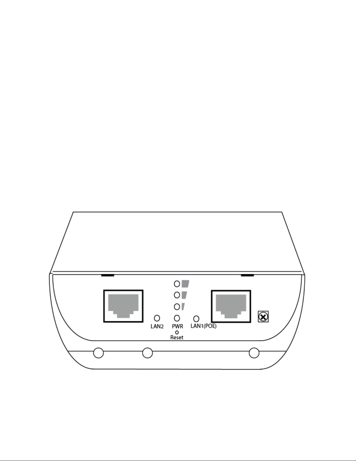
1-5 Product Overview
(1) LAN2’s Ethernet port
(2) LED Indicator for LAN2
(3) Reset Button. Press and hold the reset button for at least 15 seconds to factory reset the
device.
Page 13

(4) LAN1 (PoE) Ethernet port
(5) LED indicator for LAN1
(6) Power LED
(7) Grounding Connection: Grounding cable can protect this device from lightning strikes and
buildup of static electricity. Grounding cable not included in the package. We suggest 16-18
AWG grounding cable.
(8) LED for strong/weak WiFi Signal Indicator for Client Bridge, Repeater, WISP
(9) Ethernet cable guide ports. These can be popped out to guide your Ethernet cables out of the
device. Guide your Ethernet cables through here so you can close the outside latch.
12
Page 14
Chapter II: System and Network Setup
2-1 Build Network Connection
Please follow the following instructions to build the network connection between your new HPOW5CM
access point and your computers and other network devices:
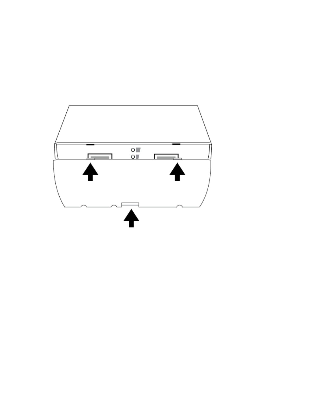
1. Remove cover from device. Press the center tab (you may need a flathead screwdriver) and the
cover should be able to be removed with a small amount of force.
13
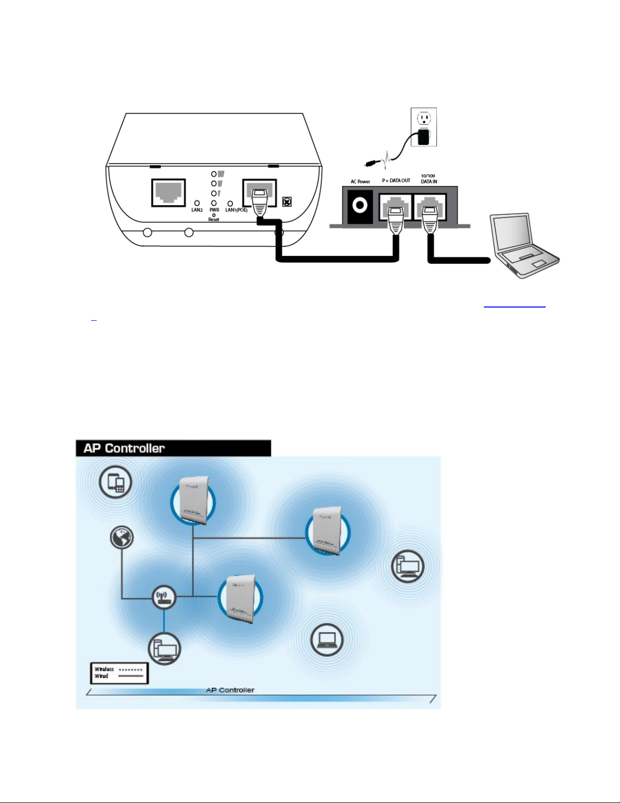
2. Connect the A/C power adapter to the wall socket, and then connect it to the ‘Power’ socket of the
PoE injector. Connect a Ethernet cable from the “P + Data Out” port on the PoE injector into the
HPOW5CM LAN1(POE) Port.
3. Connect a Ethernet cable from the “10/100 Data in” on the PoE injector to your computer/network.
Page 15
14
4. Configure the IP Address of your computer to be in the same range as the HPOW5CM (see section 2-
3)
Log into the setup page to configure the HPOW5CM
2-2 Definitions of HPOW5CM Supported Modes
The HPOW5CM supports 6 different modes.
Page 16
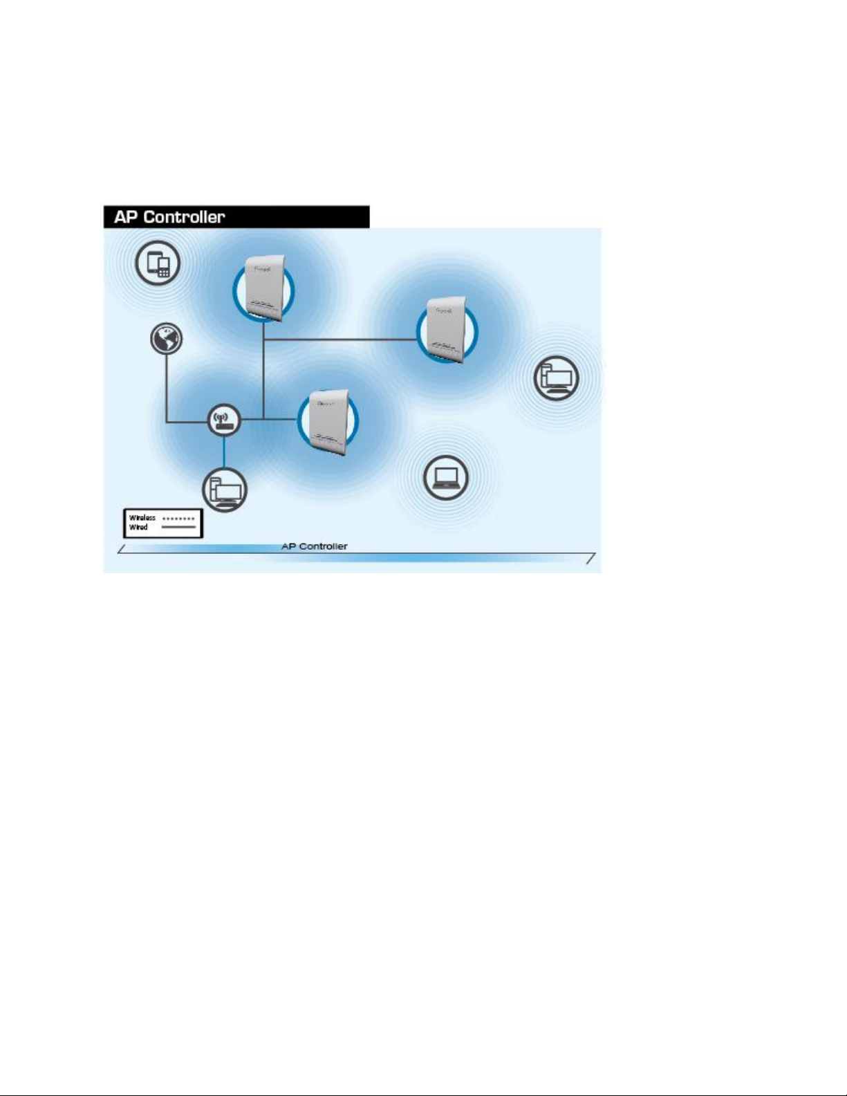
When AP Controller mode is setup, one HPOW5CM is setup to control multiple HPOW5CM’s on the
network. The HPOW5CM in AP controller mode can set IPs, configure wireless settings, monitor
wireless status, upgrade firmware and remotely controll multiple HPOW5CMs. The other HPOW5CMs
must be in AP mode. Go to section 3-1
15
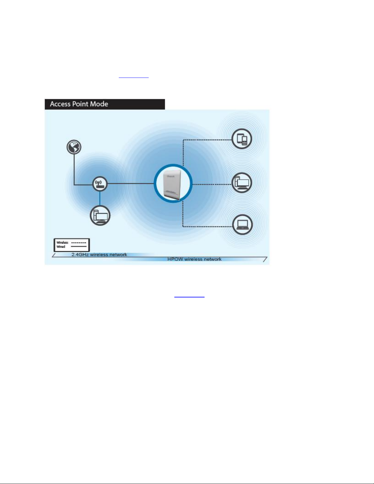
When AP mode is chosen, the system can be configured as a standard wireless access point. In this
mode, the device can be used as an Access Point for wireless client connection. All Ethernet ports wand
wireless interfaces are bridged together. Go to section 3-2
Page 17
16
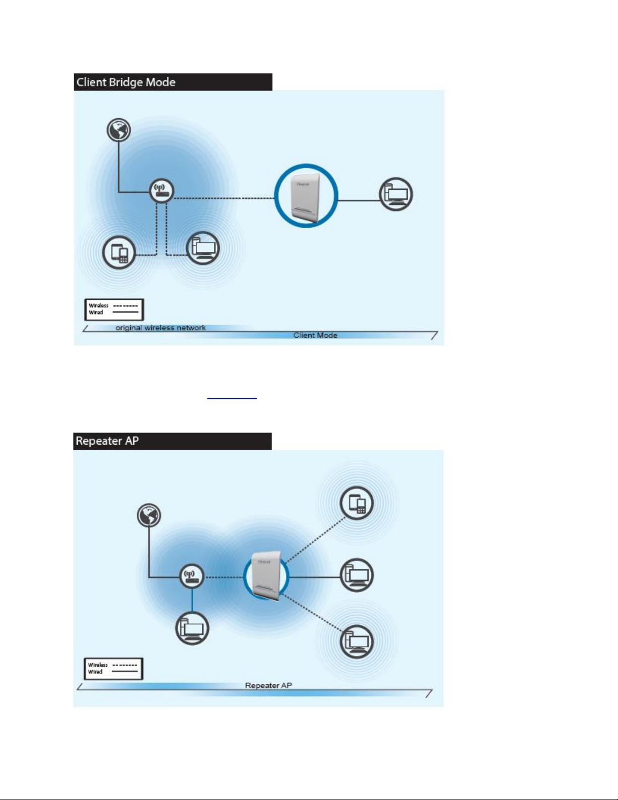
When Client Bridge + Repeater AP Mode is chosen, the system can be configured in bridged mode. In
this mode, the device can connect to other Access Points via a wireless link and be used to bridge wired
clients to the network. Go to section 3-3
Page 18
17
In this mode, the device can connect to other Access Points via a wireless link and be used to bridge
wired clients to the network and work as a wireless repeater for wireless devices. All Ethernet ports and
repeater access points are bridged together. Go to section 3-3
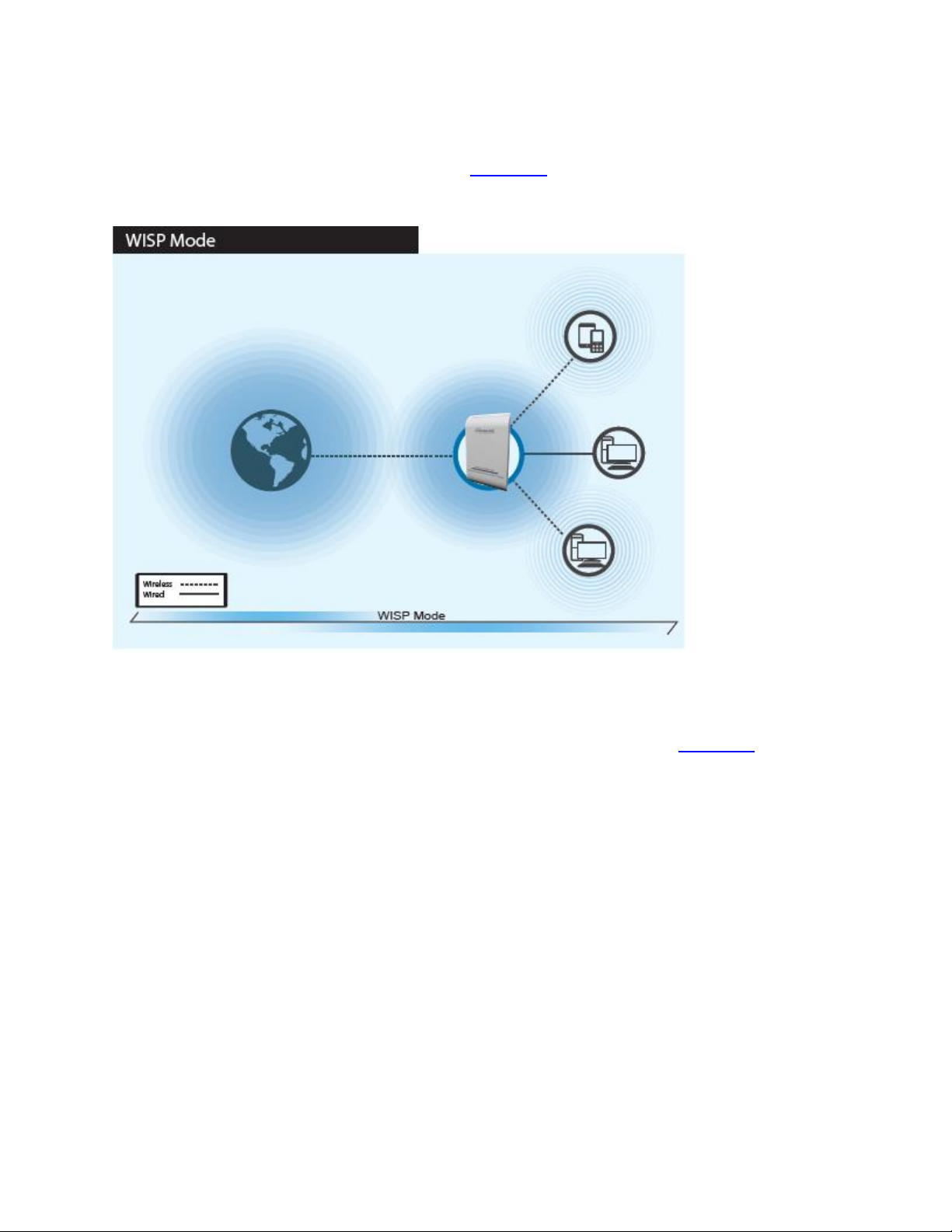
When WISP mode is chosen, the system can be configured in Wireless repeater mode. In this mode, the
device can wirelessly connect to a WISP (wireless internet service provider), ie. Another wireless AP,
HotSpot, etc. It can then wirelessly repeat the signal and can even act as a router for these signals. NAT
is enabled and wired and wireless computers can share the same IP range. Go to section 3-4
Page 19
18
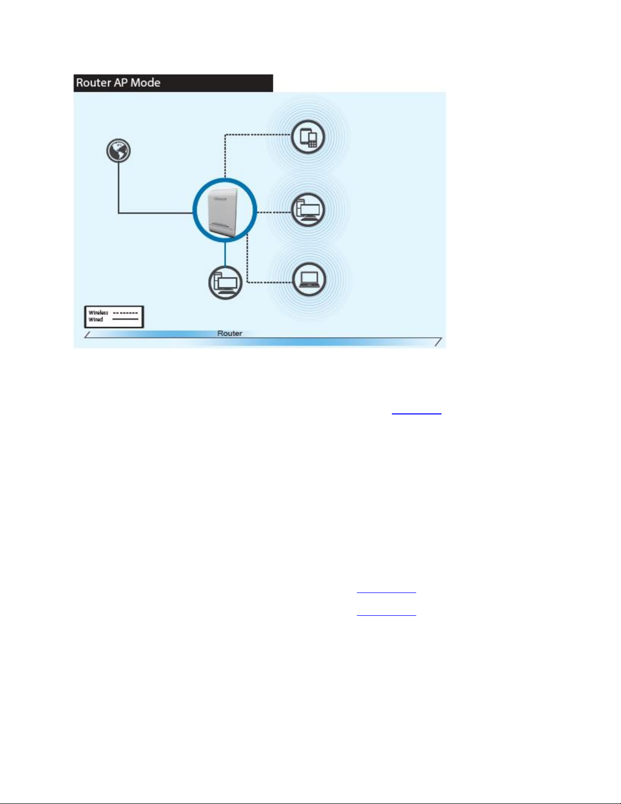
When Router AP mode is chosen, the system can be configured as a Wireless Router. In this mode, the
device is supposed to be connected to internet via ADSL/Cable Modem. The NAT is enabled and PCs in
LAN/WLAN port share the same IP to ISP through the WAN port. The connection type can be setup in
WAN page by using static IP, Dynamic IP, PPPoE or PPTP client. Go to section 3-5
2-3 Connecting to the HPOW5CM via Web Browser
After the network connection is built, the next step you should do is setup the access point with proper
network parameters, so it can work properly in your network environment.
Before you can connect to the access point and start configuration procedures, your computer must be
set to static IP. Please follow the following instructions to configure your computer to use a static IP
address:
If the operating system of your computer is….
Windows 7/8/10 - please go to section 2-3-1
Mac OS - please go to section 2-3-2
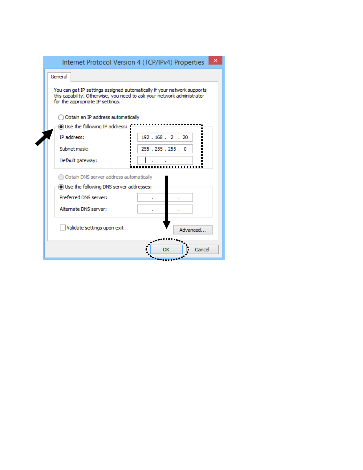
2-3-1 Windows 7/8/10 IP address setup
1. You will have to assign your computer an IP address temporarily. Note, once this is done, please
remember to change it back to ‘obtain an IP address automatically’.
Page 20
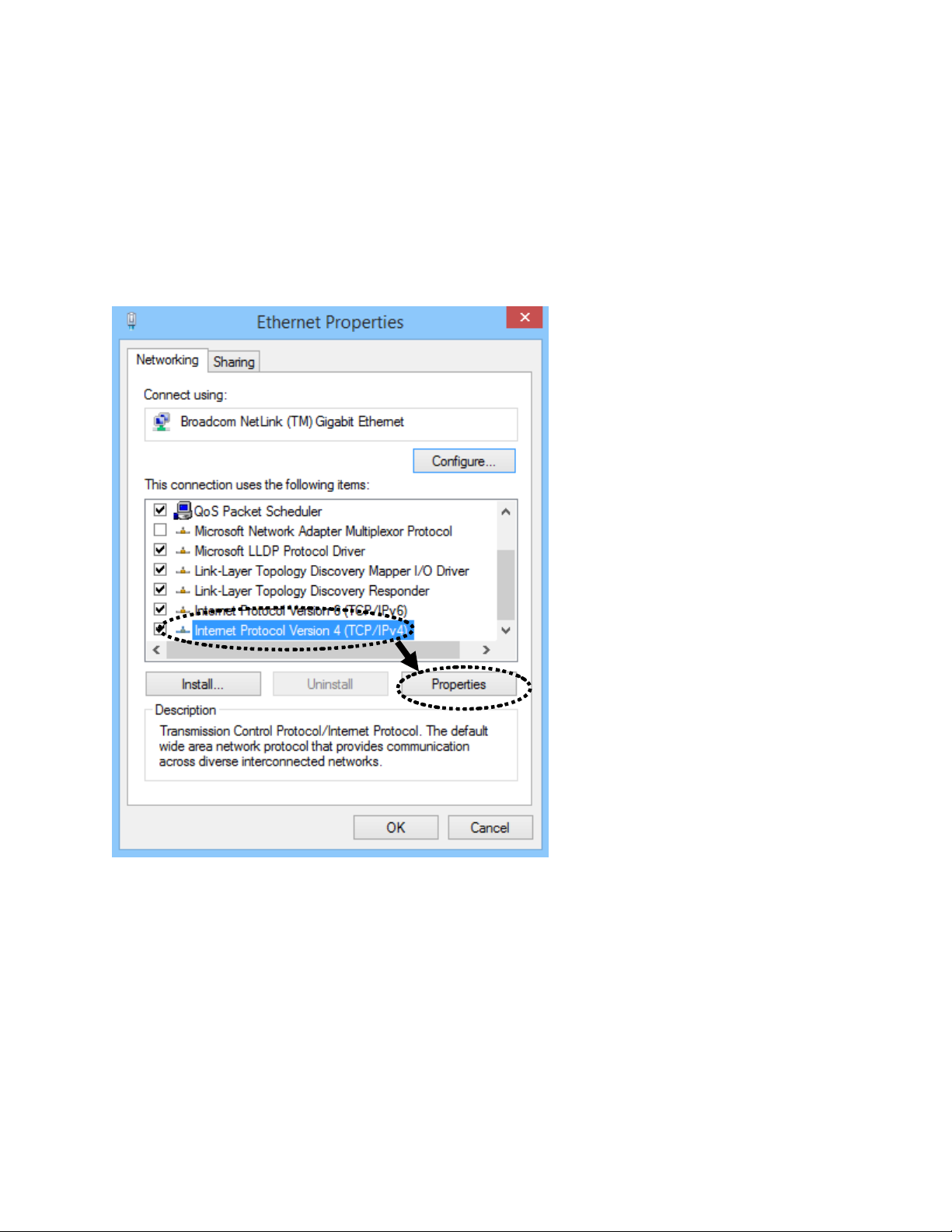
First, right click on ‘Start’ button (or left click if this is Windows 7 or below), then choose Control Panel.
Under Network and Internet, choose View Network Status and Tasks, then choose Change Adapter
Settings on the left hand column. Right-click Ethernet (or Local Area Connection), then select
‘Properties’. Ethernet (Local Area Connection) Properties window will appear, select ‘Internet Protocol
Version 4 (TCP / IPv4), and then click ‘Properties’
19
2. Select ‘Use the following IP address’, then input the following settings in respective field:
IP address: 192.168.2.20
Subnet Mask: 255.255.255.0
click ‘OK’ when finish.
Page 21
20
Page 22
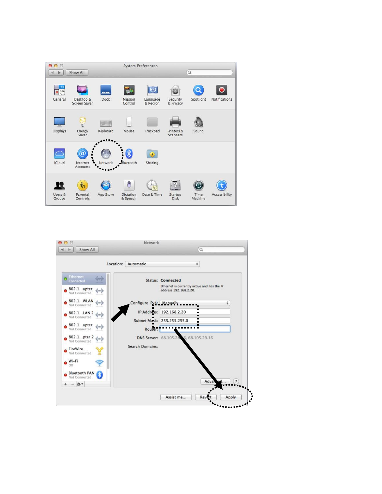
2-3-2 Mac OS X IP Address Setup
Go to your System Preferences, go to Network.
Select your Ethernet adapter. Make sure next to “Configure IPv4”, you have it set under “Manually”
IP Address 192.168.2.20
Subnet Mask: 255.255.255.0
Click ‘Apply’ when finished
21
2-3-3 Accessing the Web Page User Interface
Page 23
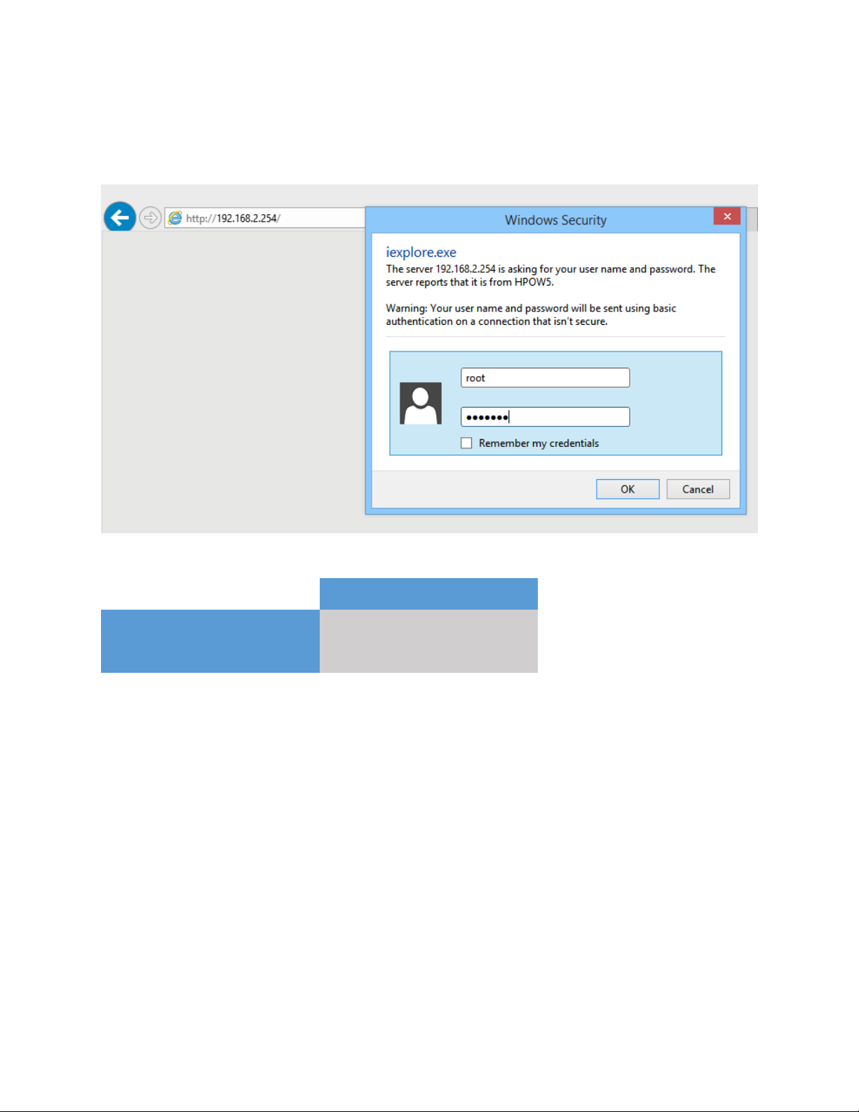
Root Account
Username:
root
Password:
default
After the IP address setup is complete, please open your web browser.
In the address field, please type: ‘192.168.2.254’ and press enter.
The following message should be shown:
22
For username and passwords, see the table below:
Page 24
Chapter III: Setup Wizard
This section will outline how to access the setup wizard and configure each of the modes in the
HPOW5CM
3-1 Controller AP Mode
23
When AP Controller mode is selected, one HPOW5CM is setup to control multiple HPOW5CM’s in AP
mode on the network. The HPOW5CM in AP controller mode can set IPs, configure wireless settings,
monitor wireless status, upgrade firmware and remotely controll multiple HPOW5CMs. Note: the other
HPOW5CMs can only be in AP Mode.
Log into the settings page, go to system and select “Mode Setup”. Choose CAP Mode. Click Save &
Reboot.
Page 25
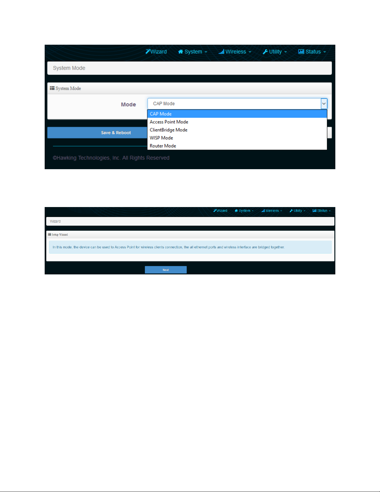
The device will now reboot.
Now, open your browser and go to 192.168.2.254. It should take you back into the settings page. Click
on “Wizard”. Click “Next”
24
3-1-1 Setup Wizard
This section is optional and will only setup the IP settings and the AP settings in CAP mode.
You can change the default IP of the device here if required. By default, the IP is 192.168.2.254
Choose your DNS type. By default, it will be received automatically but if you have a preferred DNS or
you have to specify one, please choose “specify” and enter in your values.
Page 26
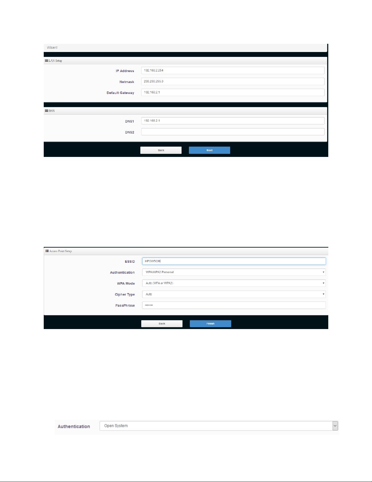
3-1-1-1 Wireless Setup
This page is used to define the parameters for the wireless for the CAP Mode. In CAP Mode, the
HPOW5CM can also act as an access point.
25
ESSID: This is the wireless broadcast name. By default, it is ‘Hawking_HPOW5CM’ but
you can change it to whatever you want.
Authentication: Choose your type of security (Hawking recommends AUTO (WPA or WPA-2PSK))
3-1-1-2 Authentication (Wireless Security) This section allows you to set up wireless security to prevent any unauthorized access to your wireless
network.
Open System (security disabled)
When you select this mode, data encryption is disabled, and every wireless device in proximity will
be able to connect your wireless access point if no other security measure is enabled
Page 27
Use this option only when you want to allow any user to use your wireless access point, and you
are not concerned about unauthorized access to your files and/or transfers over your network.
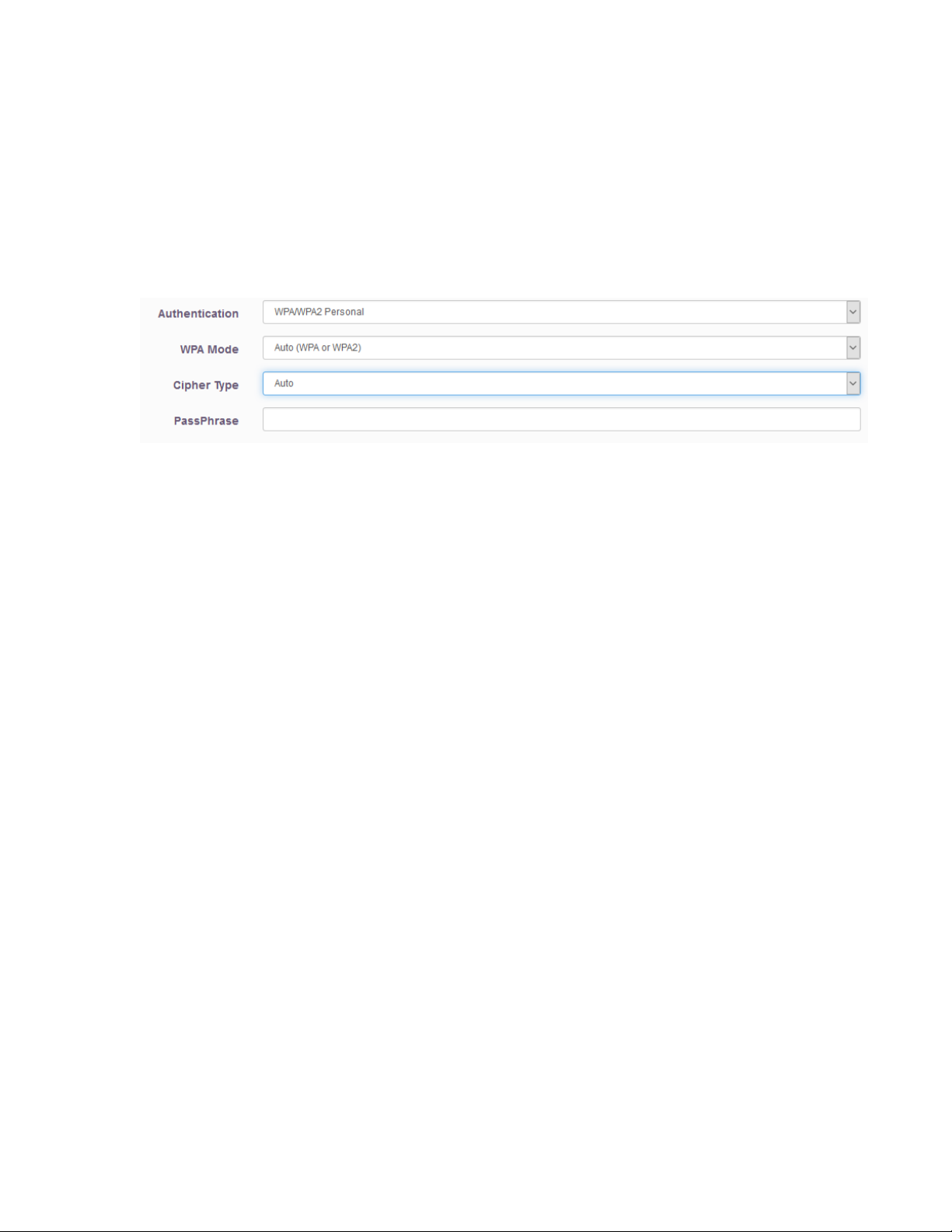
Wi-Fi Protected Access (WPA-PSK or WPA2-PSK):
When you select this mode, the wireless access point will use WPA encryption, and the following
setup menu will be shown on your web browser:
Cipher Type: AES is short for Advanced Encryption Standard, The AES cipher is specified as a
number of repetitions of transformation rounds that convert the input plain text
into the final output of ciphertext. Each round consists of several processing
steps, including one that depends on the encryption key. A set of reverse rounds
are applied to transform ciphertext back into the original plaintext using the
same encryption key. TKIP is short for Temporal Key Integrity Protocol, TKIP
scrambles the keys using a hashing algorithm and, by adding an integrity-
checking feature, ensures that the keys haven’t been tampered with.
26
Pre-shared: Enter the information for pre-shared key; the format of the information shall
according to the key type selected. Pre-shared key can be either entered as a
256-bit secret in 64 HEX digits format, or 8 to 63 ASCII characters
Hawking recommends using WPA2-PSK w/ AES cipher type as your default level of security.
Click Finish and the device will automatically restart and save your settings. After you have finished, a
network device must be connected to your network via the 10/100 Data In port on the PoE adapter or
the LAN2 port to add this device to your network. Please change your computer IP address back to
“Obtain an IP automatically”.
3-1-2 Scan AP Device
In this section, you will add other HPOW5CM’s to the Controller list.
Go to AP Control and click Scan Device. Any HPOW5CMs in AP mode will be detected.
Page 28
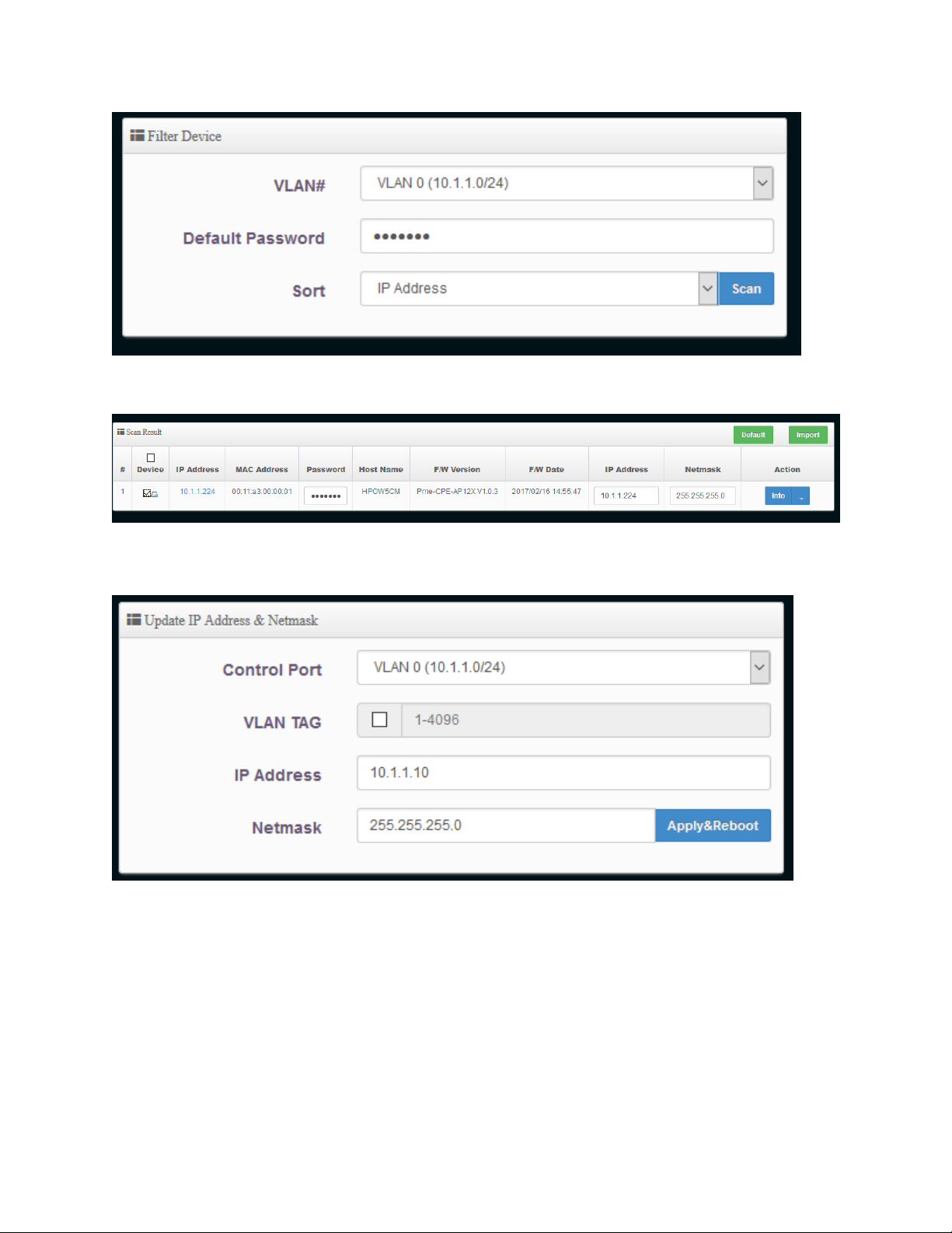
Check the device you want to import and click “Import”. This will add the AP you selected to your
Controller. You can also change the IP address settings of the devices
27
Check the device and then go to the Update IP address and Netmask and make your changes. Click
‘Apply and Reboot’
3-1-2-1 Batch setup
Go to AP Control-Batch Setup.
Page 29
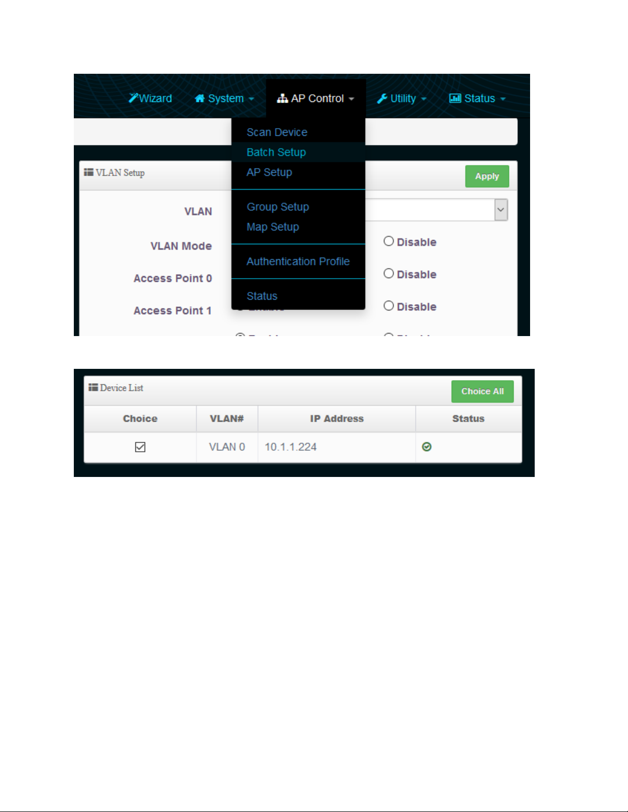
28
Check the devices you want to Batch Setup under “Device List”
Under VLAN List, you should see options to configure VLAN, Authentication Profile, Gateway & DNS,
time Server, Management, Wireless Basic Setup, Wireless Advanced Setup, VAP setup, Upgrade and
Page 30
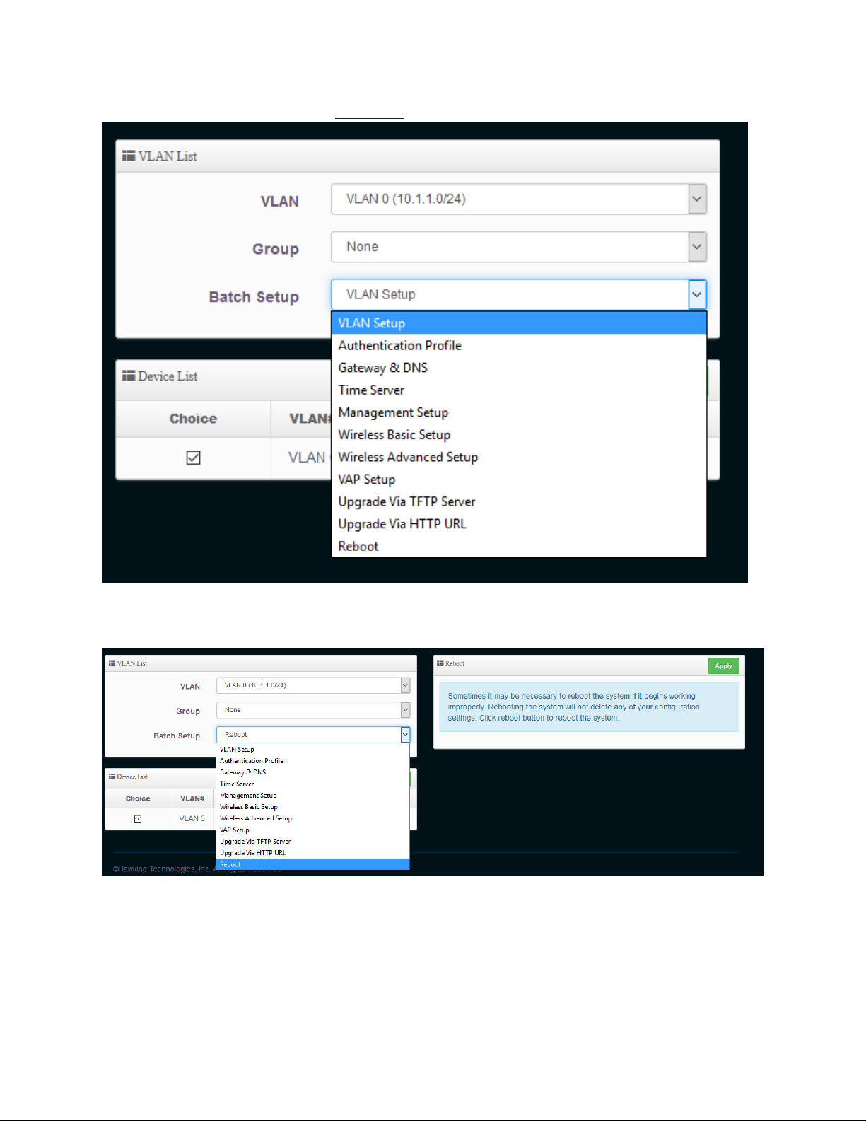
Reboot. For more information go to section 7-2
29
After you make your changes, be sure to choose “Reboot” and Apply so the changes take effect.
Page 31

3-2 AP Mode
30
When AP mode is chosen, the system can be configured as a standard wireless access point. In this
mode, the device can be used as an Access Point for wireless client connection. All Ethernet ports wand
wireless interfaces are bridged together. This section provides a detailed explanation for users on how
to configure AP mode.
Log into the settings page, go to system and select “Operating Mode”
Choose AP Mode and click save & reboot. The device will now reboot.
Now, open your browser and go to 192.168.2.254. It should take you back into the settings page. Click
on “Wizard”. Click “Next”
Page 32

3-2-1 LAN setup
You can change the default IP of the device here if required. By default, the IP is 192.168.2.254
Choose your DNS type. By default, it will be received automatically but if you have a preferred DNS or
you have to specify one, please choose “specify” and enter in your values.
31
3-2-2 Wireless Setup
This page is used to define the parameters for the wireless LAN clients
ESSID: This is the wireless broadcast name. By default, it is ‘Hawking_HPOW5CM’ but
you can change it to whatever you want.
Authentication: Choose your type of security (Hawking recommends AUTO (WPA or WPA-2PSK))
Page 33

3-2-2-1 Authentication (Wireless Security) This section allows you to set up wireless security to prevent any unauthorized access to your wireless
network
Open System (security disabled)
When you select this mode, data encryption is disabled, and every wireless device in proximity will
be able to connect your wireless access point if no other security measure is enabled
32
Use this option only when you want to allow any user to use your wireless access point, and you
are not concerned about unauthorized access to your files and/or transfers over your network.
Wi-Fi Protected Access (WPA-PSK or WPA2-PSK):
When you select this mode, the wireless access point will use WPA encryption, and the following
setup menu will be shown on your web browser:
Cipher Type: AES is short for Advanced Encryption Standard, The AES cipher is specified as a
number of repetitions of transformation rounds that convert the input plain text
into the final output of ciphertext. Each round consists of several processing
steps, including one that depends on the encryption key. A set of reverse rounds
are applied to transform ciphertext back into the original plaintext using the
same encryption key. TKIP is short for Temporal Key Integrity Protocol, TKIP
scrambles the keys using a hashing algorithm and, by adding an integrity-
checking feature, ensures that the keys haven’t been tampered with.
Page 34

33
Pre-shared Enter the information for pre-shared key; the format of the information shall
according to the key type selected. Pre-shared key can be either entered as a
256-bit secret in 64 HEX digits format, or 8 to 63 ASCII characters
Hawking recommends using WPA2-PSK w/ AES cipher type as your default level of security.
Click Finish and the device will automatically restart and save your settings. After you have finished, you
can connect the device to your network via the 10/100 Data IN port on the PoE adapter or the LAN2 port
to add this access point to your network. Please change your computer IP address back to “Obtain an IP
automatically”.
You can manually configure these settings by going to section 4-3-3
3-3 Client Bridge – Repeater Mode
When Client Bridge + Repeater Mode is chosen, the system can be configured in bridged mode. In this
mode, the device can connect to other Access Points via a wireless link and be used to bridge wired
clients to the network. It can also act as a wireless repeater. All Ethernet ports and repeater access
points are bridged together. This section provides a detailed explanation for users on how to configure
this mode.
Log into the settings page, go to system and select “Mode Setup”
Page 35

34
Choose ClientBridge Mode and click save & reboot. The device will now reboot.
Now, open your browser and go to 192.168.2.254. It should take you back into the settings page. Go to
“Wizard”. Click “Next”
3-3-1 LAN setup
You can change the default IP of the device here if required. By default, the IP is 192.168.2.254
Choose your DNS type. By default, it will be received automatically but if you have a preferred DNS or
you have to specify one, please choose “specify” and enter in your values.
Page 36

3-3-2 AP Station List Setup
This page allows you to search for an available Access Point to Connect. Click “Site Survey” for it to
automatically scan for a network to connect to.
35
Site Survey: Press this button for the device to automatically scan for wireless networks.
After it scans, a list of wireless networks in the area will appear. Click “Setup” to
connect to this network.
Page 37

ESSID: After you click setup, the name of the wireless network you wish to connect to
will appear here. You can also manually enter the name or click on “Site Survey”
for the device to scan for wireless networks.
Authentication After you click setup, the security type of the wireless network you wish to
connect to will appear here. Type in your key to connect.
36
Click Next
3-3-3 Repeater AP Setup
Page 38

37
This allows you to create a repeater AP and set SSID to your wireless network. Enable this if you want
the device to act as a wireless repeater. If your choose disable, the device will be configured ONLY as a
client bridge. If you click enable, you can set the settings for the repeater.
This page is used to define the parameters for the wireless LAN clients
ESSID: This is the wireless broadcast name in repeater mode. By default, it is ‘Default’
but you can change it to whatever you want.
Authentication: Choose your type of security (Hawking recommends AUTO (WPA or WPA-2PSK))
3-3-3-1 Authentication (Wireless Security) This section allows you to set up wireless security to prevent any unauthorized access to your wireless
network
Open System (security disabled)
When you select this mode, data encryption is disabled, and every wireless device in proximity will
be able to connect your wireless access point if no other security measure is enabled
Use this option only when you want to allow any user to use your wireless access point, and you
are not concerned about unauthorized access to your files and/or transfers over your network.
Wi-Fi Protected Access (WPA-PSK or WPA2-PSK):
When you select this mode, the wireless access point will use WPA encryption, and the following
setup menu will be shown on your web browser:
Page 39

Cipher Type: AES is short for Advanced Encryption Standard, The AES cipher is specified as a
number of repetitions of transformation rounds that convert the input plain text
into the final output of ciphertext. Each round consists of several processing
steps, including one that depends on the encryption key. A set of reverse rounds
are applied to transform ciphertext back into the original plaintext using the
same encryption key. TKIP is short for Temporal Key Integrity Protocol, TKIP
scrambles the keys using a hashing algorithm and, by adding an integrity-
checking feature, ensures that the keys haven’t been tampered with.
Pre-shared Enter the information for pre-shared key; the format of the information shall
according to the key type selected. Pre-shared key can be either entered as a
256-bit secret in 64 HEX digits format, or 8 to 63 ASCII characters
38
Hawking recommends using WPA2-PSK w/ AES cipher type as your default level of security.
Click Finish and the device will automatically restart and save your settings. After you have finished, a
network device must be connected to your network via the 10/100 Data In port on the PoE adapter or
the LAN2 port to add this client device to your network. It should not be plugged back into the main
network (should be remote). If using as a Repeater, the device just needs to be powered on via the PData Out port on the PoE adapter and can be standalone (you can also connect any wired client
computers to the 10/100 Data In Port or LAN2). Please change your computer IP address back to
“Obtain an IP automatically”.
3-4 WISP Mode
Page 40

39
When WISP Mode is chosen, the system can be configured in Wireless Internet repeater mode. In this
mode, the device can wirelessly connect to a WISP (wireless internet service provider), ie. Another
wireless AP, HotSpot, etc. It can then wirelessly repeat the signal and can even act as a router for these
signals. NAT is enabled and wired and wireless computers can share the same IP range. This section
provides a detailed explanation for users on how to configure this mode.
Choose WISP Mode
Log into the settings page, go to system and select “Mode Setup”
Choose WISP Mode and click save & reboot.
Now, open your browser and go to 192.168.2.254. It should take you back into the settings page. Go to
“Wizard”. Click “Next”
Page 41

3-4-1 WAN Settings and DNS Setings
Choose your mode. Most ISPs use “Dynamic IP”. If you are unsure, please contact your ISP. Refer to
Section 4-1 for a more in-depth explanation of these settings. Enter your hostname settings if you have
one. You may leave it blank if it is not required.
Choose your DNS type. By default, it will be received automatically but if you have a preferred DNS or
you have to specify one, please choose “specify” and enter in your values.
40
3-4-2 LAN setup
You can change the default IP of the device here if required. By default, the IP is 192.168.2.254
In router mode, by default, IP addresses will be assigned to any LAN/WLAN clients that are connected to
the device. You can disable this feature. By default, DHCP is enabled and the IP range is 192.168.2.10 –
192.168.2.70
Page 42

41
3-4-3 AP Station List Setup
This page allows you to search for an available Access Point to Connect. Click “Site Survey” for it to
automatically scan for a network to connect to.
Page 43

Site Survey: Press this button for the device to automatically scan for wireless networks.
After it scans, a list of wireless networks in the area will appear. Click “Setup” to
connect to this network.
ESSID: After you click setup, the name of the wireless network you wish to connect to
will appear here. You can also manually enter the name or click on “Site Survey”
for the device to scan for wireless networks.
42
Authentication After you click setup, the security type of the wireless network you wish to
connect to will appear here. Type in your key to connect.
Click Next
3-4-4 Repeater AP Setup
This allows you to create a repeater AP and set SSID to your wireless network.
This page is used to define the parameters for the wireless LAN clients
ESSID: This is the wireless broadcast name. By default, it is ‘Hawking_HPOW5CM’ but
you can change it to whatever you want.
Authentication: Choose your type of security (Hawking recommends AUTO (WPA or WPA-2PSK))
Page 44

3-4-4-1 Authentication (Wireless Security) This section allows you to set up wireless security to prevent any unauthorized access to your wireless
network
Open System (security disabled)
When you select this mode, data encryption is disabled, and every wireless device in proximity will
be able to connect your wireless access point if no other security measure is enabled
Use this option only when you want to allow any user to use your wireless access point, and you
are not concerned about unauthorized access to your files and/or transfers over your network.
43
Wi-Fi Protected Access (WPA-PSK or WPA2-PSK):
When you select this mode, the wireless access point will use WPA encryption, and the following
setup menu will be shown on your web browser:
Cipher Type: AES is short for Advanced Encryption Standard, The AES cipher is specified as a
number of repetitions of transformation rounds that convert the input plain text
into the final output of ciphertext. Each round consists of several processing
steps, including one that depends on the encryption key. A set of reverse rounds
are applied to transform ciphertext back into the original plaintext using the
same encryption key. TKIP is short for Temporal Key Integrity Protocol, TKIP
scrambles the keys using a hashing algorithm and, by adding an integrity-
checking feature, ensures that the keys haven’t been tampered with.
Pre-shared Enter the information for pre-shared key; the format of the information shall
according to the key type selected. Pre-shared key can be either entered as a
256-bit secret in 64 HEX digits format, or 8 to 63 ASCII characters
Hawking recommends using WPA2-PSK w/ AES cipher type as your default level of security.
Page 45

44
Click Finish and the device will automatically restart and save your settings. After you have finished, this
device will act as a Wireless Internet Service Provider. The device just needs be powered on via the PData Out port on the PoE adapter and can be standalone (you can also connect any wired clients to the
10/100 Data in Port on LAN2). Please change your computer IP address back to “Obtain an IP
automatically.
3-5 Router Mode
When Router mode is chosen, the system can be configured as a Wireless Router. In this mode, the
device is supposed to be connected to internet via ADSL/Cable Modem. The NAT is enabled and PCs in
LAN/WLAN port share the same IP to ISP through the WAN port. The connection type can be setup in
WAN page by using static IP, Dynamic IP, PPPoE or PPTP client. This section provides a detailed
explanation for users on how to configure Router AP mode.
Log into the settings page, go to system and select “Mode Setup”
Page 46

45
Choose Router Mode and click save & reboot. The device will now reboot. After the device has finished
rebooting, you will have to make changes to your computer’s physical connection. See below.
The physical setup is slightly different than the standard setup. Plug your computer into LAN2 on the
access point. Plug your ISP’s modem into the PoE ‘10/100 data in’ port.
Now, open your browser and go to 192.168.2.254. It should take you back into the settings page. Go to
system and select “Setup Wizard”. Click “Next”
Page 47

3-5-1 WAN Settings and DNS Settings
Choose your mode. Most ISPs use “Dynamic IP”. If you are unsure, please contact your ISP. Refer to
Section 4-1 for a more in-depth explanation of these settings. Enter your hostname settings if you have
one. You may leave it blank if it is not required.
Choose your DNS type. By default, it will be received automatically but if you have a preferred DNS or
you have to specify one, please choose “specify” and enter in your values.
46
3-5-2 LAN setup
You can change the default IP of the device here if required. By default, the IP is 192.168.2.254
In router mode, by default, IP addresses will be assigned to any LAN/WLAN clients that are connected to
the device. You can disable this feature. By default, DHCP is enabled and the IP range is 192.168.2.10 –
192.168.2.70
Page 48

47
3-5-3 Wireless Setup
This page is used to define the parameters for the wireless LAN clients
ESSID: This is the wireless broadcast name. By default, it is ‘Hawking_HPOW5CM’ but
you can change it to whatever you want.
Authentication Choose your type of security (Hawking recommends AUTO (WPA or WPA-2PSK))
Page 49

3-5-3-1 Authentication (Wireless Security) This section allows you to set up wireless security to prevent any unauthorized access to your wireless
network
Open System (security disabled)
When you select this mode, data encryption is disabled, and every wireless device in proximity will
be able to connect your wireless access point if no other security measure is enabled
Use this option only when you want to allow any user to use your wireless access point, and you
are not concerned about unauthorized access to your files and/or transfers over your network.
Wi-Fi Protected Access (WPA-PSK or WPA2-PSK):
When you select this mode, the wireless access point will use WPA encryption, and the following
setup menu will be shown on your web browser:
48
Cipher Type: AES is short for Advanced Encryption Standard, The AES cipher is specified as a
number of repetitions of transformation rounds that convert the input plain text
into the final output of ciphertext. Each round consists of several processing
steps, including one that depends on the encryption key. A set of reverse rounds
are applied to transform ciphertext back into the original plaintext using the
same encryption key. TKIP is short for Temporal Key Integrity Protocol, TKIP
scrambles the keys using a hashing algorithm and, by adding an integrity-
checking feature, ensures that the keys haven’t been tampered with.
Pre-shared Enter the information for pre-shared key; the format of the information shall
according to the key type selected. Pre-shared key can be either entered as a
256-bit secret in 64 HEX digits format, or 8 to 63 ASCII characters
Hawking recommends using WPA2-PSK w/ AES cipher type as your default level of security.
Click Finish and the device will automatically restart and save your settings. After you have finished, you
can connect the device to your network via LAN2 to use this as a Router AP. You can add a network
switch to LAN2 if you need more Ethernet ports. Please change your computer IP address back to
“Obtain an IP automatically”.
Page 50

Settings can be modified via the VLAN setup after configuration is complete. See section 4-3.
49
Page 51

Chapter IV: System Settings
Under this heading, several settings can be changed to configure this device
4-1 WAN Setup
Click under system, WAN setup. (This feature is only available under Router and WISP mode)
4-1-1 Internet Connection Type: Static IP
Static IP users can manually setup the WAN IP w/ a static IP provided by the Internet Service Provider
(ISP).
IP Address, IP Netmask (subnet mask), IP Gateway are all provided by the ISP. Contact them if you are
not sure.
50
4-1-2 Internet Connection Type: Dynamic IP (Default)
Dynamic IP users receive all their IP, Subnet, Gateway and DNS settings from their ISP. This is the most
common setting used.
Page 52

51
Hostname: (optional). If your ISP uses dynamic IP addresses, you may need to enter
a hostname provided by the ISP.
4-1-3 Internet Connection Type: PPPoE
PPPoE users need to manually enter their ISP provided username/password. Please contact them if you
are not sure.
Username: Enter user name for PPPoE connection
Password: Enter user name for PPPoE connection.
MTU: By default, it is 1492 bytes. Consult with your ISP for correct MTU
setting.
Page 53

Reconnect Mode: Always on – A connection to internet is always maintained
On Demand – A connection to internet is made as needed
Manual – Click on the “Connect” button on “WAN information” in the
overview page to connect to the internet.
4-1-4 Internet Connection Type: PPTP
The Point-to-Point Tunneling Protocol (PPTP) mode enables the implementation of secure multiprotocol Virtual Private Networks (VPN) through public networks.
52
Username: Username of the PPTP connection
Password: Password of the PPTP connection
Page 54

PPTP Server IP Address: The IP address of the PPTP Server
WAN IP: IP Address of the WAN port
IP Netmask (Subnet): The subnet mask of the WAN port
PPTP Server IP address: The IP address of the PPTP server
MTU: By default, it is 1492 bytes. Consult with your ISP for correct MTU
setting.
MPPE Encryption: Microsoft Point-to-Point Encryption (MPPE) encrypts data in Point-to-
Point Protocol (PPP)-based dial-up connections or Point-to-Point
Tunneling Protocol (PPTP) virtual private network (VPN) connections.
128-bit key (strong) and 40-bit key (standard) MPPE encryption schemes
are supported. MPPE provides data security for the PPTP connection
that is between the VPN client and the VPN server.
Reconnect Mode: Always on – A connection to internet is always maintained
On Demand – A connection to internet is made as needed
53
Manual – Click on the “Connect” button on “WAN information” in the
overview page to connect to the internet.
4-1-5 DNS
“No default DNS server” (default) or “Specify a DNS server IP” to setup a system DNS.
Primary: The IP Address of the Primary DNS server
Secondary: The IP address of the secondary DNS server
4-1-6 MAC Clone
The MAC address is a 12-digit HEX code uniquely assigned to hardware as identification. Some ISPs
require you to register a MAC address in order to access to Internet. If not, you could use default MAC
or clone MAC from a PC.
Page 55

Default MAC Address: Keep the default MAC address of WAN port on the system.
Manual MAC Address: Enter the MAC address registered with your ISP.
4-2 LAN Setup
Setup local IP Address/Netmask/Gateway/DNS and management. (This feature is only available under
Router and WISP mode)
54
4-2-1 LAN IP Setup
The administrator can set it to obtain (Dynamic IP) an IP automatically or manually setup (Static IP) the
LAN IP address of the device.
If you select Dynamic IP, you can input your host name (if required)
If you Static IP, you can enter in your settings here:
Page 56

IP Address: The IP address of the LAN port; default IP address is 192.168.2.254
Netmask: The Subnet mask of the LAN port; default Netmask is 255.255.255.0
4-2-2 DNS
Check “No default DNS server” (default) or “Specify a DNS server IP” to setup a system DNS.
55
Primary: The IP Address of the Primary DNS server
Secondary: The IP address of the secondary DNS server
4-2-3 802.1d Spinning Tree
The spanning tree network protocol provides a loop free topology for a bridged LAN between LAN
interface and 8 WDS interfaces from wds0 to wds7. The Spanning Tree Protocol, which is also referred
to as STP, is defined in the IEEE Standard 802.1d.
Page 57

4-3 VLAN Setup
The VLAN setup is used to configure VLANs. Click under System, VLAN Setup.
56
VLAN Mode: Number of VLANs (6 supported)
VLAN Flag: Modes that are supported
IP Address: IP address assigned to VLAN
Netmask: Subnet Mask assigned to VLAN
RADIO: WiFi frequency supported
Action: Click “Network” button for configuring VLAN settings
4-3-1 VLAN Network Settings
Click the Network button next to the VLAN you want to configure.
Page 58

VLAN Mode: Enable/Disable to enable VLAN
57
IP/Netmask Setup: Assign an IP address for specific VLAN
Access Point: Enable/Disable the Wireless Radio
802.1d Spanning Tree: The spanning tree network protocol provides a loop free topology for a bridged
LAN between LAN interface and 8 WDS interfaces from wds0 to wds7. The
Spanning Tree Protocol, also referred to as STP, is defined in the IEEE 802.1d
standard.
Page 59

Control Port: Select one of the VLANs to be managed AP.
58
ETH VLAN Tag Setup: Enable/Disable and create your tags
4-3-2 VLAN DHCP Service
Devices connected to the system can obtain an IP address automatically when this service is enabled.
(This feature is only available in Router, ClientBridge + Repeater and WISP Modes)
Page 60

59
DHCP: Check Enable button to activate this function or Disable to deactivate this
service.
Start IP / End IP: Specify the range of IP addresses to be used by the DHCP server when assigning
IP address to clients. The default range IP address is 192.168.2.10 to
192.168.2.70.
Netmask: Set IP Netmask, Default 255.255.255.0
DNS1 IP: Enter IP address of the first DNS server; this field is required.
DNS2 IP: Enter IP address of the second DNS server; this is optional.
Page 61

60
WINS IP: Enter IP address of the Windows Internet Name Service (WINS) server; this is
optional.
Domain: Enter the domain name for this network.
Lease Time: The IP addresses given out by the DHCP server will only be valid for the duration
specified by the lease time. Increasing the time ensure client operation without
interruptions, but could introduce potential conflicts. Lowering the lease time
will avoid potential address conflicts, but might cause more interruptions to the
client while it will acquire new IP addresses from the DHCP server. Default is
86400 seconds
Static Lease IP List
This function allows you to assign a static IP address to a specific computer forever, so you don’t have
to set the IP address for a computer, and still enjoy the benefit of using DHCP server. (This feature is
only available in Router AP and WISP AP Modes)
Comment: You can enter a comment, for reference to the IP address you assigned. Ie “work
computer, Living Room, etc.
IP Address: Input the IP address you want to assign to this computer or network device
Mac Address: Input the MAC address of the computer or network device (total 12 characters,
with character from 0 to 9, and from a to f, like ‘001122aabbcc’) Click “Add” to
add the IP list to the table below.
Page 62

61
4-3-3 VLAN Access Point
For each Virtual AP, users can configure general settings and security. Click “edit” on the Virtual AP you
wish to edit.
ESSID: Extended Service Set ID indicates the SSID which the clients used to connect to
the VAP. ESSID will determine the service type of a client which is assigned to the
specified VAP.
SSID Visibility: Select this option to enable the SSID to broadcast in your network. When
configuring the network, it is suggested to enable this function but disable it
when the configuration is complete. With this enabled, someone could easily
obtain the SSID information with the site survey software and get unauthorized
access to a private network. With this disabled, network security is enhanced
and can prevent the SSID from begin seen on networked.
Client Isolation: Select Enable, all clients will be isolated from each other. That means all clients
cannot reach to other clients.
Connection/User Limit: Enable if you want to have a user limit. Enter maximum number of clients to a
desired number. For example, while the number of client is set to 32, only 32
clients are allowed to connect with this VAP.
IAPP: Inter Access-Point Protocol is designed for the enforcement of unique association
throughout a ESS(Extended Service Set) and for secure exchange of station's
security context between current access point (AP) and new AP during hand off
Page 63

period. Notice: IAPP only used on WPA-PSK and WPA2-PSK security type. Only
one of VAPs can be enabled.
Authentication: Choose your type of security you want to use for this Access Point
Open System: Data are unencrypted during transmission when this option is
selected.
62
WPA-PSK (or WPA2-PSK): WPA-PSK is short for W-Fi Protected Access-PreShared Key. WPA-SPK uses the same encryption way with WPA, and the only
difference between them is that WPA-PSK recreates a simple shared key, instead
of using the user’s certification.
Cipher Type: You can chose use AES or TKIP with your WPA / WPA2
encryption method,
AES is short for Advanced Encryption Standard. The AES cipher is
specified as a number of repetitions of transformation rounds that
convert the input plaintext into the final output of ciphertext. Each
round consists of several processing steps, including one that depends
on the encryption key. A set of reverse rounds are applied to transform
ciphertext back into the original plaintext using the same encryption key.
Page 64

63
TKIP is short for “Temporal Key Integrity Protocol. TKIP scrambles the
keys using a hashing algorithm and, by adding an integrity-checking
feature, ensures that the keys haven’t been tampered with.
Group Key Update Period: This time interval for re-keying GTK
(broadcast/multicast encryption keys) in seconds. Enter the time-length
required; the default time is 600 seconds.
Passphrase: Enter the information for pre-shared key; the format of the
information shall according to the key type selected. Pre-shared key can
be either entered as a 256-bit secret in 64 HEX digits format, or 8 to 63
ASCII characters.
WPA-Enterprise (or WPA2-Enterprise) General Setting The RADIUS
authentication and encryption will be both enabled if this selected.
Cipher Type: You can chose use AES or TKIP with your WPA / WPA2
encryption method,
AES is short for “Advanced Encryption Standard”, The AES cipher is
specified as a number of repetitions of transformation rounds that
convert the input plaintext into the final output of ciphertext. Each
round consists of several processing steps, including one that depends
on the encryption key. A set of reverse rounds are applied to transform
ciphertext back into the original plaintext using the same encryption key.
TKIP is short for “Temporal Key Integrity Protocol”, TKIP scrambles the
keys using a hashing algorithm and, by adding an integrity-checking
feature, ensures that the keys haven’t been tampered with.
Page 65

64
Group Key Update Interval: This time interval for re-keying GTK
(broadcast/multicast encryption keys) in seconds. Enter the time-length
required; the default time is 600 seconds.
Authentication RADIUS Server Settings
Radius Server: Enter the IP address of the Authentication RADIUS server.
Radius Port: The port number used by Authentication RADIUS server.
Use the default 1812 or enter port number specified.
Radius Secret: The secret key for system to communicate with
Authentication RADIUS server. Support 1 to 64 characters.
WEP 802.1x: When WEP 802.1x Authentication is enabled, please refer to the
following Dynamic WEP and RADIUS settings to complete the configuration.
Key Size: Check on the respected button to enable either 64bits or
128bits key length. The system will automatically generate WEP keys for
encryption.
Radius Server: Enter the IP address of the Authentication RADIUS server.
Radius Port: The port number used by Authentication RADIUS server.
Use the default 1812 or enter port number specified.
Radius Secret: The secret key for system to communicate with
Authentication RADIUS server. Support 1 to 64 characters.
4-3-4 VLAN Mac Filter
For each VLAN AP, users can allow or reject clients based on their MAC address.
Page 66

65
Action: Select the desired access control type from the drop-down list; the options are
Disable, Allow or Reject.
Only Allow List MAC: Define certain wireless clients in the list which will have
granted access to the Access Point while the access will be denied for all the
remaining clients – Action Type is set to “Only Allow List MAC”.
Only Deny List MAC: Define certain wireless clients in the list which will have
denied access to the Access Point while the access will be granted for all the
remaining clients - Action Type is set to “Only Deny List MAC”. MAC Access
Control is the weakest security approach. WPA or WPA2 security methods should
be used when possible.
Mac Address: Type in the Mac address of the client you wish to add under the Mac filter.
4-3-5 VLAN 802.11r Fast Roaming
The HPOW5CM supports 802.11r function for 2.4GHz. This allows the client to make the initial
handshake with the AP is done even before the client gets in range of the AP.
Page 67

66
Fast Roaming: Enable or Disable the feature here. Default is disabled.
Mobility Domain: MDID is used to indicate a group of Aps (within an ESS, ie. Sharing the same
SSID) between which a STA can use Fast BSS Transition. Please enter 2-octet
identifier as a hex string.
R0 Key Lifetime: Default lifetime of the PMK-RO in minutes, the default is 10000, administrator
can set 1-65535
Reassoc deadline: Reassociation deadline in time units (Tus / 1.024 ms; range 1000-65535).
Default: 1000
R0/NAS Identifier: PMK-R0 Key Holder identifier. When using IEEE 802.11r, nas_identifier must be
set and must be between 1 and 48 octets long.
R1 Identifier: PMK-R1 Key Holder identifier 6-octet identifier as a hex string
R1 Push: Administrator can select enable/disable. If enable, the function will
automatically send the R1 Key
R0 Key Address:
Page 68

67
To enable roaming between multiple AP devices, the first AP must key in the MAC address of the second
AP and vice versa. The NAS Identifier and 128-bit key should be identical on both Aps. This will enable
device roaming between both APs.
Mac Address: Administrators must enter the MAC address of the other AP
NAS Identifier: Enter 1-48 octets of network domain name
128-bit Key: Enter shared key
R0 Key Holder List
After setting up R0 Key Holder, the information will appear on this list.
R1 Key Holder List:
Enter a unified set of R1 Key Holder Identification certification.
Page 69

Mac Address: Administrators must enter the MAC address of the other AP
NAS Identifier: Enter 1-48 octets of network domain name
128-bit Key: Enter shared key
R1 Key Holder List
68
After setting up R1 Key Holder, the information will appear on this list.
4-4 Authentication
This function is for web authentication. It supports authentication for local users / Radius Servers /
0Auth2.0 and Guest. The system supports 7 VLANs with web authentication.
Page 70

#: Displays 7 VLANs
Authentication: Displays VLAN # and whether enable/disable web authentication
Action: Choose authentication or select drop down.
4-4-1 Authentication
Click on the authentication button to get into the basic settings
69
Authentication: Enable/disable
Multiple Login: Set one account or multiple users to simultaneously login (0 = not limited)
Login Timeout: After account login with no traffic, system with automatically timeout. Enter
time in minutes.
Redirect URL: After successful login, system will redirect to URL.
Login URL: Set URL for login page
Session Log: If network has Syslog server, account session log will copy to syslog server
Local User: Can create a local user account.
RADIUS: Enter security information for remote RADIUS Server
Bandwidth Control: Can control traffic by users or total
Page 71

4-4-2 Guest
If enabled, the administrator can set guest count limit / login time, type and flow control
70
Service: Enable/Disable
Login Type: One Time: login to start counting until end of time
Multiple Times: logout time will stop counting until the next relogin to start
counting
Count Limit: Set guest limit
Page 72

Login Time: With a certain timefame with no traffic, system will auto logout
QoS: Restrict traffic of guest. Set user upload/download traffic
4-4-3 Local User
Create a local user account for web login
Username: User account
Password: Account password
71
4-4-4 OAuth2.0
Supports Facebook and Google by default. Users can add additional OAuth2.0 servers through UI
settings.
#: Display items.
Active: Display on/off status for the authentication.
Provider: Display authentication server. The system default use authentication server for
Google and Facebook
4-4-5 POP3 Server
Allows clients to link a POP3 server for receiving emails from a remote server
Page 73

POP3 Server: Enable/Disable
Display Name: Set the display name based on POP3 user/client
Host: Host Server Name
Port: Port number for Host Server
72
Connect Type: STARTTLS, SSL/TTL or none.
POP3 Server Test: Test to see if the settings are operating correctly.
4-4-6 Customize Page
This function allows the user to customize the user login page. This supports multiple languages and
HTML editing.
Page Setup
Template: Administrator can select Enable or disable.
Page 74

73
Select enable to active default Login Page
Select disable to activate HTML Source Code Window for Customization
4-4-7 Customize Language
User can create other languages for login page.
Page 75

74
4-4-8 Walled Garden
This function provides certain free services or advertisement web pages for users to access the websites
listed before login and authentication. User without the network access right can still have a chance to
experience the actual network service free of charge in Walled Garden URL list.
Display Name: Set name of Website.
IP Address/Domain: Set IP or Domain of the Open the website.
Full URL: Set full website name.
4-4-9 Privilege Address
This function provides local device can access Internet without authentication. If there are some
workstations belonging NGS Access Point that need to access to network without authentication, enter
the IP or MAC address of these workstations in this list.
4-4-10 Profile
Administrator can backup/upload current authentication configuration and login page for HTML Source
Page 76

4-5 DHCP Setup
Devices connected to the system can obtain an IP address automatically when this service is enabled.
(This feature is only available in Router and WISP Modes)
75
Page 77

76
DHCP: Check Enable button to activate this function or Disable to deactivate this
service.
Start IP / End IP: Specify the range of IP addresses to be used by the DHCP server when assigning
IP address to clients. The default range IP address is 192.168.2.10 to
192.168.2.70, the netmask is 255.255.255.0
DNS1 IP: Enter IP address of the first DNS server; this field is required.
DNS2 IP: Enter IP address of the second DNS server; this is optional.
WINS IP: Enter IP address of the Windows Internet Name Service (WINS) server; this is
optional.
Page 78

77
Domain: Enter the domain name for this network.
Lease Time: The IP addresses given out by the DHCP server will only be valid for the duration
specified by the lease time. Increasing the time ensure client operation without
interruptions, but could introduce potential conflicts. Lowering the lease time
will avoid potential address conflicts, but might cause more interruptions to the
client while it will acquire new IP addresses from the DHCP server. Default is
86400 seconds
Static Lease IP List
This function allows you to assign a static IP address to a specific computer forever, so you don’t have
to set the IP address for a computer, and still enjoy the benefit of using DHCP server. (This feature is
only available in Router AP and WISP AP Modes)
Comment: You can enter a comment, for reference to the IP address you assigned. Ie “work
computer, Living Room, etc.
IP Address: Input the IP address you want to assign to this computer or network device
Mac Address: Input the MAC address of the computer or network device (total 12 characters,
with character from 0 to 9, and from a to f, like ‘001122aabbcc’) Click “Add” to
add the IP list to the table below.
Page 79

4-6 Management Setup
Administrators can setup system info, passwords and login methods. Click under System, Management
4-6-1 System Information System
Name: Enter a desired name or use the default one.
Description: Provide description of the system.
78
Location: Enter geographical location information of the system.
4-6-2 Root Password
Full administrative rights and access to all aspects of the configuration
New Password: Enter a new password if desired
Check New Password: Enter the same new password again
4-6-3 Admin Login Methods:
Only root user can enable or disable system login methods and change services port.
Page 80

Enable HTTP: Check to select HTTP Service.
79
Enable HTTPS: Check to select HTTPS Service
HTTPS Port: The default is 443 and the range is between 1 ~ 65535.
Enable Telnet: Check to select Telnet Service
Telnet Port : The default is 23 and the range is between 1 ~ 65535
Enable SSH: Check to select SSH Service
SSH Port : Please The default is 22 and the range is between 1 ~ 65535.
Click “Generate Key” button to generate RSA private key. The “host key footprint” gray blank will display
content of RSA key.
4-6-4 System Log Setup
Administrator can be the backup system log or authentication log to remote server. Please enter the IP
address and port of the remote sys log server.
Page 81

4-6-5 Auto Reboot
The device can be set to auto reboot in a daily, weekly, or monthly setting.
80
4-7 Time Server Setup
System time can be configured via this page, and manual setting or via a NTP server is supported. Please
go to System, Time Server
Local Time: Display the current system time.
Mode: Select NTP Server or Manual
Setup Time Using NTP
Synchronize the system time with NTP server. System can autoupdate the system time.
Page 82

Default NTP Server: Select the NTP Server from the drop-down list.
Time Zone: Select a desired time zone from the drop-down list.
Daylight saving time: Enable or disable Daylight saving.
Setup Time Using Manual
81
The user can manually set time/date
Date: Set the date for system.
Time: Set the time for system.
4-8 PoE PassThrough
This device supports PoE Bridge function. If this is enabled, the Ethernet port LAN2 will allow other PoE
devices to be powered through the secondary LAN port
Service: the default is disabled but user can enable the feature here
Page 83

4-9 SNMP Setup
SNMP is an application-layer protocol that provides a message format for communication between
SNMP managers and agents. By enabling SNMP function, the administrator can obtain the system
information remotely. You can access the settings by going to System, SNMP
SNMP v2c Enable
Check to enable SNMP v2c.
82
RO Community: Set a community string to authorize read-only access.
RW Community: Set a community string to authorize read/write access.
SNMP v3 Enable
Check to enable SNMP v3. SNMP v3 supports the highest level SNMP security.
RO Username: Set a community string to authorize read-only access.
Page 84

RO Password: Set a password to authorize read-only access.
RW User: Set a community string to authorize read/write access.
RW Password: Set a password to authorize read/write access.
SNMP Trap
Events such as cold start, interface up & down, and association & disassociation will report to an
assigned server.
83
Community: Set a community string required by the remote host computer that will receive
trap messages or notices send by the system.
IP (1~4): Enter the IP addresses of the remote hosts to receive trap messages.
Page 85

Chapter V: Wireless Setup
5-1 General Setup
This section allows you to set the data transmission, channel and output power for the system
5-1-1 Radio Basic Setup
84
MAC Address: The MAC address of the Wireless interface is displayed here.
Country: This device only supports United States WiFi channels.
Band Mode: Please select the wireless band you wish to use. By selecting different band
setting, you’ll be able to allow or deny the wireless client of a certain band.
If you select 802.11b only wireless clients using the wireless band you select
802.11b will be able to connect to this access point. (Maximum transfer rate
11Mbps)
If you select 802.11b/g, then only wireless clients using 802.11b and 802.11g
band will be able to connect to this access point. (Maximum transfer rate
11Mbps for 802.11b clients, and maximum 54Mbps for 802.11g clients)
If you want to allow 802.11b, 802.11g, and 802.11n clients to connect to this
access point, select 802.11b/g/n (Maximum transfer rate 11Mbps for 802.11b
clients, maximum 54Mbps for 802.11g clients, and maximum 300Mbps for
802.11n clients) (Default).
Page 86

If you select 802.11n, the only wireless clients using 802.11n band will be able to
connect to this access point. (Maximum 300Mbps for 802.11n clients)
Auto Channel: Enable/Disable the function. If disabled, the WiFi channel will be fixed to the
manually selected channel.
Channel: Please select a channel from the dropdown list of ‘Channel Number’, You can
choose any channel number you want to use, and almost all wireless clients can
locate the channel you’re using automatically without any problem. However,
it’s still useful to remember the channel number you use, as some wireless clients
support manual channel number selecting, and this would help in certain
scenarios when there are radio communication conflicts
By default, it is on AUTO but if you have a specific channel you wish to use, you
can select it here.
Tx Power: You can adjust the output power of the access point to get the appropriate
coverage for your wireless network. Specify power levels between level 1 and
level 9. Level 9 is the maximum setting.
85
Slot Time: Slot time is in the range of 9-1489ms. Default value is 9ms.
Slot time is the amount of time a device waits after a collision before
retransmitting a packet. Reducing the slot time decreases the overall back-off,
which increases throughput. Back-off, which is a multiple of the slot time, is the
random length of time a station waits before sending a packet on the LAN.
ACK Timeout: ACK Timeout is in the range of 1-372ms. Default value is 64ms.
All data transmissions in the 802.11b/g request an “Acknowledgement” (ACK) by
the receiving radio. The transmitter will resend the original network packet if
the ACK failed to arrive with the specified interval.
5-1-2 HT Physical Mode
Page 87

86
Tx/Rx Stream: 2 is the default setting. Using 1 will halve your speed.
Channel Bandwidth: The "20/40” MHz option is usually best. The other option is available for special
circumstances.
Extension Channel: Only for Channel Bandwidth “40” MHz. Select the desired channel bonding for
control. Upper supports 1-7 and lower supports 5-11
MCS: This parameter represents transmission rate. By default (Auto) the fastest
possible transmission rate will be selected. You have the option of selecting the
speed if necessary.
Shout GI: Short Guard Interval, by default, it's “Enabled” so throughput can be increased.
However, it can also increase error rate in some installations, due to increased
sensitivity to radio-frequency reflections. Select the option that works best for
your installation.
Aggregation: By default, it's “Enable”. It allows sending multiple frames per single access to
the medium by combining frames together into one larger frame. It creates the
larger frame by combining smaller frames with the same physical source and
destination end points and traffic class (i.e. QoS) into one large frame with a
common MAC header.
Aggregation Frames: The Aggregation Frames is in the range of 2~64, default is 32. It determines the
number of frames combined on the new larger frame.
Page 88

Aggregation Size: The Aggregation Size is in the range of 1024~65535, default is 50000. It
determines the size (in Bytes) of the larger frame.
5-2 Advanced Settings
The administrator can change the Slot Time, ACK Timeout, RTS threshold and fragmentation threshold
settings for the system
87
Beacon Interval: Beacon Interval is in the range of 40~3500 and set in unit of millisecond. The
default value is 100 msec. Access Point (AP) in IEEE 802.11 will send out a special
approximated 50-byte frame, called “Beacon”. Beacon is broadcast to all the
stations, provides the basic information of AP such as SSID, channel, encryption
keys, signal strength, time stamp, support data rate. All the radio stations
received beacon recognizes the existence of such AP, and may proceed to the
next actions if the information from AP matches the requirement. Beacon is sent
on a periodic basis. The time interval can be adjusted. By increasing the beacon
interval, you can reduce the number of beacons and associated overhead, but
that will likely delay the association and roaming process because stations
scanning for available access points may miss the beacons. You can decrease the
beacon interval, which increases the rate of beacons. This will make the
association and roaming process very responsive; however, the network will
incur additional overhead and throughput will go down.
DTIM Interval: The DTIM interval is in the range of 1~255. The default is 1. DTIM is defined as
Delivery Traffic Indication Message. It is used to notify the wireless stations,
Page 89

88
which support power saving mode, when to wake up to receive multicast frame.
DTIM is necessary and critical in wireless environment as a mechanism to fulfill
power-saving synchronization.
A DTIM interval is a count of the number of beacon frames that must occur
before the access point sends the buffered multicast frames. For instance, if
DTIM Interval is set to 3, then the Wi-Fi clients will expect to receive a multicast
frame after receiving three Beacon frame. The higher DTIM interval will help
power saving and possibly decrease wireless throughput in multicast
applications.
Fragment Threshold: Set the fragment threshold of the wireless radio. The default value is 2346.
RTS Threshold: RTS Threshold is in the range of 1~2347 byte. The default is 2347 byte. The main
purpose of enabling RTS by changing RTS threshold is to reduce possible
collisions due to hidden wireless clients. RTS in AP will be enabled automatically
if the packet size is larger than the Threshold value. By default, RTS is disabled in
a normal environment supports non-jumbo frames.
Short Preamble: By default, its set to “Enabled”. If Disabled, the device will use Long 128-bit
Preamble Synchronization field. The preamble is used to signal "here is a train of
data coming" to the receiver. The short preamble provides 72-bit
Synchronization field to improve WLAN transmission efficiency with less
overhead.
IGMP Snooping: The process of listening to Internet Group Management Protocol (IGMP)
network traffic. The feature allows a network switch to listen in on the IGMP
conversation between hosts and routers. By listening to these conversations the
switch maintains a map of which links need which IP multicast streams.
Multicasts may be filtered from the links which do not need them and thus
controls which ports receive specific multicast traffic.
Greenfield: In wireless WLAN technology, greenfield mode is a feature of major components
of the 802.11n specification. The greenfield mode feature is designed to improve
efficiency by eliminating support for 802.11b/g devices in an all draft-n network.
In greenfield mode the network can be set to ignore all earlier standards.
5-3 WMM QoS
This affects traffic flowing from the access point to the client station. Configuring QoS options consists of
setting parameters on existing queues for different types of wireless traffic. You can configure different
minimum and maximum wait times for the transmission of packets in each queue based on the
requirements of the media being sent. Queues automatically provide minimum transmission delay for
Voice, Video, multimedia, and mission critical applications, and rely on best-effort parameters for
traditional IP data.
Page 90

As an Example, time-sensitive Voice & Video, and multimedia are given effectively higher priority for
transmission (lower wait times for channel access), while other applications and traditional IP data
which are less time-sensitive but often more data-intensive are expected to tolerate longer wait times.
High throughput. Bulk data that requires maximum throughput and is not time-sensitive is sent to this
queue (FTP data, for example). Medium throughput and delay. Most traditional IP data is sent to this
queue. Minimum delay. Time-sensitive video data is automatically sent to this queue. Time-sensitive
data like VoIP and streaming media are automatically sent to this queue.
89
CWmin: Determines the initial random backoff wait time ("window") for retry of a
transmission. The value specified here in the Minimum Contention Window is the
upper limit (in milliseconds) of a range from which the initial random backoff
wait time is determined.
CWmax: Maximum Contention Window. The value specified here in the Maximum
Contention Window is the upper limit (in milliseconds) for the doubling of the
random backoff value. This doubling continues until either the data frame is sent
or the Maximum Contention Window size is reached. Once the Maximum
Contention Window size is reached, retries will continue until a maximum
number of retries allowed is reached. Valid values for the "cwmax" are 1, 3, 7,
15, 31, 63, 127, 255, 511, or 1024. The value for "cwmax" must be higher than
the value for "cwmin".
AIFS The Arbitration Inter-Frame Spacing Number specifies a wait time (in
milliseconds) for data frames
TxOP Limit Transmission Opportunity is an interval of time when a WME AP has the right to
initiate transmissions onto the wireless medium (WM). This value specifies (in
milliseconds) the Transmission Opportunity (TXOP) for AP; that is, the interval of
time when the WMM AP has the right to initiate transmissions on the wireless
network.
Page 91

ACM bit: Admission Control Mandatory, ACM only takes effect on AC_VI and AC_VO.
When you do not click Checkbox, it means that the ACM is controlled by the
connecting AP. If you click Checkbox, it means that the Client is in charge
No ACK policy bit: Acknowledgment Policy, WMM defines two ACK policies: Normal ACK and No
ACK. Click “Checkbox” indicates “No ACK”
When the no acknowledgement (No ACK) policy is used, the recipient does not acknowledge received
packets during wireless packet exchange. This policy is suitable in the environment where
communication quality is fine and interference is weak. While the No ACK policy helps improve
transmission efficiency, it can cause increased packet loss when communication quality deteriorates.
This is because when this policy is used, a sender does not retransmit packets that have not been
received by the recipient. When the Normal ACK policy is used, the recipient acknowledges each
received uncast packet.
5-4 Station Setup
90
The network manager can configure related wireless settings, AP Setup, Security Settings, and Access
Control Settings.
Administrators can configure ESSID, SSID broadcasting, Maximum number of client associations, security
type settings and MAC Filter settings. (This feature is only available in Client Bridge + Repeater and
WISP Modes)
5-4-1 AP Station Security Settings
ESSID: Extended Service Set ID. In station mode, this should be the network you are
connecting to.
Security Type: Select the desired security type from the drop-down list; the options are Open
System, Shared Key, WPA/WPA2 Personal. Setting should match the network
being connected to.
Page 92

Open System: Data are unencrypted during transmission when this option is
selected.
Shared Key: WEP, Wired Equivalent Privacy, is a data encryption mechanism
based on a 64-bit, or 128-bit. Select Shared Key as the security type from the
drop down list as desired.
91
Key Size: The key size of WEP encryption can be 64bit, 128bit.
Key Index: You can select the Key which you want to use. Other wireless
station must have the same key value to connect with the device, 4
different WEP keys can be configured at the same time, but only one is
used. Effective key is set with a choice of WEP Key 1, 2, 3 or 4.
Network Key #: You can chose either HEX or ASCII for your WEP key
value, for 64bit encryption strength can use 10 digits for HEX (0~9, a~f
and A-F) or 5 digits for ASCII (0~9, a~z and A~Z), for 128bit encryption
strength can use 26 digits for HEX (0~9, a~f and A-F) or 13 digits for
ASCII (0~9, a~z and A~Z), for 152bit encryption strength can use 32 digits
for HEX (0~9, a~f and A-F) or 16 digits for ASCII (0~9, a~z and A~Z)
WPA-PSK (or WPA2-PSK): WPA-PSK is short for W-Fi Protected Access-PreShared Key. WPA-SPK uses the same encryption way with WPA, and the only
difference between them is that WPA-PSK recreates a simple shared key, instead
of using the user’s certification.
Page 93

92
Cipher Type: You can chose use AES or TKIP with your WPA / WPA2
encryption method
AES is short for Advanced Encryption Standard. The AES cipher is
specified as a number of repetitions of transformation rounds that
convert the input plaintext into the final output of ciphertext. Each
round consists of several processing steps, including one that depends
on the encryption key. A set of reverse rounds are applied to transform
ciphertext back into the original plaintext using the same encryption key.
TKIP is short for “Temporal Key Integrity Protocol. TKIP scrambles the
keys using a hashing algorithm and, by adding an integrity-checking
feature, ensures that the keys haven’t been tampered with.
PassPhrase: Enter the information for pre-shared key; the format of the
information shall according to the key type selected. Pre-shared key can
be either entered as a 256-bit secret in 64 HEX digits format, or 8 to 63
ASCII characters.
5-5 Repeater AP Setup
Settings for Repeater. (This feature is only available in Client Bridge + Repeater and WISP Modes)
Page 94

93
Access Point: Choose Enable or Disable Repeater AP function, the default is Disable
ESSID: Extended Service Set ID. When users are browsing for available wireless
networks, this is the SSID that will appear in the list..
SSID Visibility: By default, it is “Disable”. Enable this option to stop the SSID broadcast in your
network. When disabled, people could easily obtain the SSID information with
the site survey software and get access to the network if security is not turned
on. When enabled, network security is enhanced.
Client Isolation: By default, it is “Disable”. Select “Enable”, all clients will be isolated from each
other, which means they cannot reach each other.
Connection Limit: Enable/Disable user limits.
User Limits: The default value is 64. You can enter the number of wireless clients that can
associate to a particular SSID. When the number of client is set to 5, only 5
clients at most are allowed to connect to this VAP.
IAPP: Enable/Disable for IAPP roaming. IAPP condition must use WPA-2PSK AES
security
Authentication: Select the desired security type from the drop-down list; the options are Open,,
WPA-PSK/WPA2-PSK Personal, WPA/WPA2-Enterprise and WEP 802.1X.
Page 95

94
Open System: Data are unencrypted during transmission when this option is
selected.
WPA-PSK (or WPA2-PSK): WPA-PSK is short for W-Fi Protected Access-PreShared Key. WPA-SPK uses the same encryption way with WPA, and the only
difference between them is that WPA-PSK recreates a simple shared key, instead
of using the user’s certification.
Cipher Type: You can chose use AES or TKIP with your WPA / WPA2
encryption method,
AES is short for Advanced Encryption Standard. The AES cipher is
specified as a number of repetitions of transformation rounds that
convert the input plaintext into the final output of ciphertext. Each
round consists of several processing steps, including one that depends
on the encryption key. A set of reverse rounds are applied to transform
ciphertext back into the original plaintext using the same encryption key.
Page 96

95
TKIP is short for “Temporal Key Integrity Protocol. TKIP scrambles the
keys using a hashing algorithm and, by adding an integrity-checking
feature, ensures that the keys haven’t been tampered with.
Group Key Update Period: This time interval for re-keying GTK
(broadcast/multicast encryption keys) in seconds. Enter the time-length
required; the default time is 600 seconds.
Passphrase: Enter the information for pre-shared key; the format of the
information shall according to the key type selected. Pre-shared key can
be either entered as a 256-bit secret in 64 HEX digits format, or 8 to 63
ASCII characters.
WPA-Enterprise (or WPA2-Enterprise) General Setting The RADIUS
authentication and encryption will be both enabled if this selected.
Cipher Type: You can chose use AES or TKIP with your WPA / WPA2
encryption method,
AES is short for “Advanced Encryption Standard”, The AES cipher is
specified as a number of repetitions of transformation rounds that
convert the input plaintext into the final output of ciphertext. Each
round consists of several processing steps, including one that depends
on the encryption key. A set of reverse rounds are applied to transform
ciphertext back into the original plaintext using the same encryption key.
TKIP is short for “Temporal Key Integrity Protocol”, TKIP scrambles the
keys using a hashing algorithm and, by adding an integrity-checking
feature, ensures that the keys haven’t been tampered with.
Page 97

96
Group Key Update Interval: This time interval for re-keying GTK
(broadcast/multicast encryption keys) in seconds. Enter the time-length
required; the default time is 600 seconds.
Authentication RADIUS Server Settings
Radius Server: Enter the IP address of the Authentication RADIUS server.
Radius Port: The port number used by Authentication RADIUS server.
Use the default 1812 or enter port number specified.
Radius Secret: The secret key for system to communicate with
Authentication RADIUS server. Support 1 to 64 characters.
WEP 802.1x: When WEP 802.1x Authentication is enabled, please refer to the
following Dynamic WEP and RADIUS settings to complete the configuration.
Key Size: Check on the respected button to enable either 64bits or
128bits key length. The system will automatically generate WEP keys for
encryption.
Radius Server: Enter the IP address of the Authentication RADIUS server.
Radius Port: The port number used by Authentication RADIUS server.
Use the default 1812 or enter port number specified.
Radius Secret: The secret key for system to communicate with
Authentication RADIUS server. Support 1 to 64 characters.
Page 98

5-6 Repeater AP MAC Filter
For each Repeater AP, users can allow or reject clients based on their MAC address. Click on Wireless,
Repeater AP MAC Filter Setup. (This feature is only available in Client Bridge + Repeater AP and WISP
Modes)
97
Action: Select the desired access control type from the drop-down list; the options are Disable,
Allow or Reject.
Only Allow List MAC: Define certain wireless clients in the list which will have
granted access to the Access Point while the access will be denied for all the
remaining clients – Action Type is set to “Only Allow List MAC”.
Only Deny List MAC: Define certain wireless clients in the list which will have
denied access to the Access Point while the access will be granted for all the
remaining clients - Action Type is set to “Only Deny List MAC”. MAC Access
Control is the weakest security approach. WPA or WPA2 security methods should
be used when possible.
Mac Address: Type in the Mac address of the client you wish to add under the Mac filter.
5-7 WDS Setup
The administrator could create WDS Links to expand wireless network. When WDS is enabled, access
point functions as a wireless bridge and is able to communicate with other access points via WDS links. A
Page 99

98
WDS link is bidirectional and both side must support WDS. Access points know each other by MAC
Address. In other words, each access point needs to include MAC address of its peer. Ensure all access
points are configured with the same channel and own same security type settings. (This feature is only
available in AP Mode)
Security Type: Option is “Disable”, “WEP”, “TKIP” or “AES” from drop-down list.
AES Key: Enter 8 to 63 ASCII or 64 HEX format AES key.
Note that the security key must be the same on all WDS Peer Devices in order to build WDS links. Security
type takes effect when WDS is enabled.
WDS MAC List Enable: Check “Enable” to create WDS link.
Page 100

99
WDS Peer's MAC Address: Enter the MAC address of WDS peer.
Note: All WDS peers need to have same WiFi Channel and same Security Type.
5-8 WDS Status
This page shows the status of each WDS enabled device on the network. (This feature is only available in
AP Mode)
MAC Address: Display MAC address of WDS devices.
RSSI: Indicate the RSSI of the respective WDS's link.
TX/RX Rate: Indicate the TX/RX Rate of the respective WDS's link
Disconnect: Administrator can kick out a specific client, click “Delete” button to kick out
specific WDS's link.
 Loading...