

Page 1
1
Page 2

Trademarks & Copyright
Windows 95/98/ME and Windows NT/2000/XP are registered trademarks of Microsoft Corp. All other brands and
product names are trademarks of their respective companies.
No part of this publication may be reproduced in any form or by any means or used to make any derivative (such as
translation, transformation or adaptation) without the express written consent of the manufacturer as stipulated by the
United States Copyright Act of 1976.
FCC Certifications
This equipment has been tested and found to comply with the limits for a Class B digital device, pursuant to Part 15 of the
FCC Rules. These limits are designed to provide reasonable protection against harmful interference in a residential
installation. This equipment generates, uses and can radiate radio frequency energy and, if not installed and used in
accordance with the instructions, may cause harmful interference to radio communications. However, there is no
guarantee that interference will not occur in a particular installation. If this equipment does cause harmful interference to
radio or television reception, which can be determined by turning the equipment off and on, the user is encouraged to try
to correct the interference by one or more of the following measures:
• Reorient or relocate the receiving antenna.
• Increase the separation between the equipment and receiver.
• Connect the equipment into an outlet on a circuit different from that to which the receiver is connected.
• Consult the dealer or an experienced radio/TV technician for help.
Shielded interface cables must be used in order to comply with emission limits.
You are cautioned that changes or modifications not expressly approved by the party responsible for compliance could
void your authority to operate the equipment.
This device complies with Part 15 of the FCC rules. Operation is subject to the following two conditions: (1) This device
may not cause harmful interference, and (2) This device must accept any interference received, including interference that
may cause undesired operation.
CE Mark Warning
This is a Class B product. In a domestic environment, this product may cause radio interference, in which case the user
may be required to take adequate measures.
All trademarks and brand names are the property of their respective proprietors.
Specifications are subject to change without prior notification.
HAWKING LIMITED WARRANTY
Hawking Technology guarantees that every HPOE1 Power Over Ethernet Adapter Kit is free from physical
defects in material and workmanship under normal use for (1) year from the date of purchase. If the product
proves defective during this one-year warranty period, call Hawking Customer Service in order to obtain a Return
Authorization number. Warranty is for repair or replacement only. Hawking Technology does not issue any
refunds. BE SURE TO HAVE YOUR PROOF OF PURCHASE. RETURN REQUESTS CANNOT BE
PROCESSED WITHOUT PROOF OF PURCHASE. When returning a p roduct, mark the Return Authorization
number clearly on the outside of the package and include your original proof of purchase.
IN NO EVENT SHALL HAWKING TECHNOLOGY’S LIABILTY EXCEED THE PRICE PAID FOR THE
PRODUCT FROM DIRECT, INDIRECT, SPECIAL, INCIDENTAL OR CONSEQUENTIAL DAMAGES
RESULTING FROM THE USE OF THE PRODUCT, ITS ACCOMPANYING SOFTWARE OR ITS
DOCUMENTATION. Hawking Technology makes no warranty or representation, expressed, implied or
statutory, with respect to its products or the contents or use of this documentation and all accompanying software,
and specifically disclaims its quality, performance, merchantability, or fitness for any particular purpose.
Hawking Technology reserves the right to revise or update its products, software, or documentation without
obligation to notify any individual or entity. Please direct all inquiries to:
techsupport@hawkingtech.com.
2
Page 3

Overview 4
Features 5
Package Content 6
Hardware Description 7
Installation 10
Technical Specifications 12
3
Page 4
The HPOE1 Power-Over-Ethernet (PoE) Adapter Kit provides both data and AC power
through an Ethernet cable to non PoE-equipped devices, such as access points, IP cameras, and
other devices that do not have built-in PoE functionality.
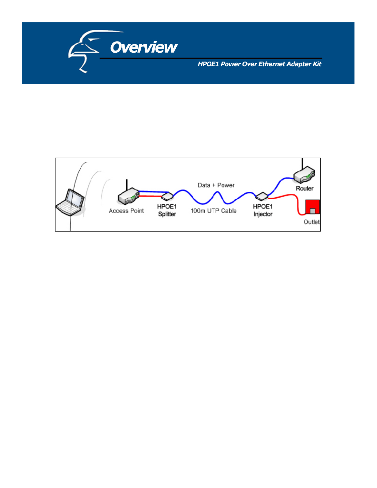
The PoE adapter kit is easy to install. The diagram below shows a typical application for
the PoE Adapter Kit.
Figure 1. PoE Adapter Kit Application
Figure 1 above shows that the PoE Injector unit’s Ethernet (LAN) port is connected to an
Ethernet port on the router via a standard RJ-45 Ethernet cable. (It can also be connected to an
Ethernet port on a switch or hub.) The Injector unit’s 48V/0.4A Power-In port is connected to a
standard wall outlet via the power adapter that is included in the HPOE1’s packaging. On the
other end of the Injector unit, the Power + Data-Out port is connected to the Splitter unit’s
Power + Data-In port via a standard RJ-45 Ethernet cable. As the port names indicate, both
data and power are transmitted via this RJ-45 cable that connects the Injector and Splitter units.
On the other end of the Splitter unit, the LAN port is connected to a network device’s
LAN port via an RJ-45 cable. (The network device can be an access point, a network camera,
or other network device.) The Splitter unit’s DC-Out power port is connected to the network
device’s power port via the Power Link cable that is included with the packaging. The Splitter
unit’s DIP switch is adjusted to a voltage setting that matches the network device’s listed power
setting. (For example, if the device is a network camera with a 5V power specification, the
Splitter’s DIP switch would be set to “5V”.)
For more detailed instructions on how to set up the PoE Adapter Kit with a network
device, please refer to the chapter titled “Installation” on page 8 of this user’s manual.
4
Page 5

• Transmits both data and power via a standard RJ-45 Ethernet cable
• Delivers DC power and data to non-PoE network devices
• Delivers power over up to 100 meters
• Short-circuit protection
• Adjustable output settings (5v/1.5A, 7.5v/1A, and 12v/1A) to match the power setting of
your associated network device
• Remote power feeding
• Lightweight and compact
• Plug-and-Play
5
Page 6
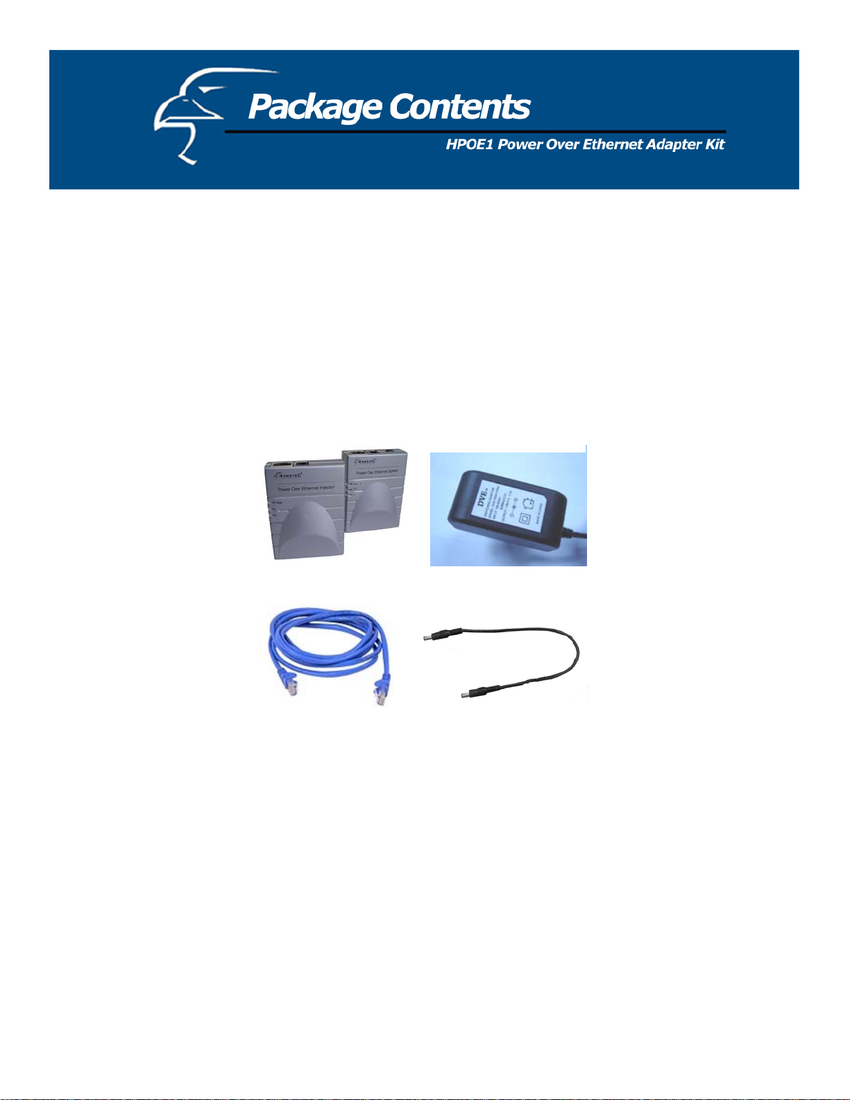
1. Power over Ethernet Injector
2. Power over Ethernet splitter
3. Power adapter 48V/0.4A
4. RJ-45 Ethernet Cable
5. Power Link Cable (Male-to-Male)
6. User’s Manual
Figure 2. Package Contents
6
Page 7
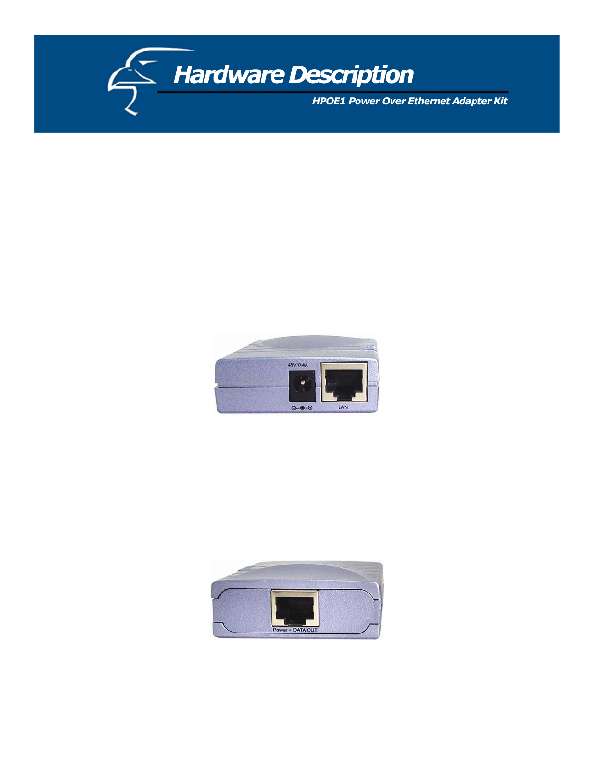
Power over Ethernet Injector
The Power over Ethernet Injector has three connection ports and one LED indicator (Power).
The following is a brief description:
• Data-In (LAN) port: This is the RJ-45 Ethernet port for data transmission into the PoE
Injector.
This port connects to a router, switch, or hub.
• Power-In port: The Power-In port supplies power into the Injector.
Figure 3. The Injector’s Data-In and Power-In ports
• Power + Data-Out port: This is an RJ-45 Ethernet port and connects to the PoE
Splitter’s Power + Data-In port via a standard Ethernet cable. The RJ-45 Ethernet cable
delivers both data and power to the PoE Splitter.
Figure 4. The Injector’s Power + Data-Out port
7
Page 8

Power over Ethernet Splitter
The Power over Ethernet Splitter has three connection ports, three LED indicators, and a
voltage adjustment DIP switch.
• Power + Data-In port: This is an RJ-45 Ethernet port for data and power
transmission into the PoE Splitter. This port connects to the PoE Injector’s Power +
Data-Out port via an RJ-45 Ethernet cable. The RJ-45 Ethernet cable delivers both
data and power to the PoE Splitter.
Figure 5. The Splitter’s Power + Data-In port
• Data-Out port: This is an RJ-45 Ethernet port and connects to a network device such
as an IP camera via an RJ-45 Ethernet cable. This cable will transmit data to and from
the network device.
• Power-Out port: The Power-Out port transmits DC power to a 5V, 7.5V or 12V
network device via the Data Link cable that is included with the packaging.
Figure 6. The Splitter’s Data-Out port, Power Out port, and DIP Switch
8
Page 9

LED indicators: There are three LEDs on the top of PoE Splitter. The LEDs are listed
according to power output status: 5V (also Power), 7.5V, or 12V.
Figure 7. Power and Voltage Status LED Indicators
• DIP switch: The DIP switch adjusts the splitter voltage, allowing for the PoE Adapter
to operate with a variety of different PoE-capable network devices, such as IP
cameras, access points, and more. It has three voltage settings: 5V, 7.5V and 12V.
The default setting is 12V. Before adjusting the DIP switch, please remember to
disconnect the power from the Splitter.
Figure 8. DIP switch
9
Page 10

This Installation section will provide you with general instructions on how to set up the HPOE1
Adapter Kit with PoE-capable devices by walking you through two examples: 1. Installing the
HPOE1 Adapter Kit and connecting it to an IP camera (Hawking’s HNC290G Wireless-G
Network Camera will be used for this example), and 2. Installing the HPOE1 adapter kit and
connecting it to an access point (Hawking’s HWBA54G Wireless-G Multi-Function AP/Bridge
will be used for this example).
Installing the PoE Adapter Kit and connecting it to an IP camera (IP cameras are also called
“network cameras”; the terms will be used interchangeably in the instructions below.):
1. Connect the Data-In (LAN) port on the PoE Injector to a LAN (Ethernet) port on a
router, switch, or hub using a standard RJ-45 Ethernet cable.
2. Using another RJ-45 Ethernet cable, connect the Power + Data-Out port on the PoE
Injector to the Power + Data-In port on the PoE Splitter.
3. Plug the included 48V/0.4A power adapter into the PoE Injector’s 48V/0.4A Power-In
port. (You do not need to plug the power adapter into the wall outlet yet.)
4. Connect the Data-Out (LAN) port on the PoE Splitter to the LAN (Ethernet) port on the
HNC290G Network Camera using a standard RJ-45 Ethernet cable. (Note: All network
cameras, whether wired or wireless, will have a LAN port.)
5. Using the DIP switch that sits next to the DC-Out port, adjust the voltage setting on the
PoE Splitter to match that of the HNC290G IP camera (in this case, 12V). (In general, for
any PoE-capable network device that you connect to the PoE Splitter, you must adjust the
Splitter’s DIP switch to match the voltage setting of the network device. If you are unsure
of the network device’s voltage setting, you can find it in the device’s user’s manual or
datasheet, and sometimes on its packaging.) The PoE Splitter supports three voltage
settings: 5V, 7.5V, and 12V. The default setting is 12V. Note: You must adjust the DIP
switch to match the voltage setting on the network device before connecting the included
power link cable (described in the following step) and turning the power on.
6. Next, connect one end of the included Power Link cable to the DC Out port on the PoE
Splitter. Then, connect the other end of the cable to the IP Camera’s power input port
on the back of the unit.
7. Finally, ensure that all the connections are correct, and then plug the 48V/0.4A power
adapter into the wall outlet. The installation process is now complete. If you have
already installed and set up your IP camera, you can verify that the PoE Adapter Kit–IP
Camera system is working properly by typing the camera’s IP address into your web
browser’s address bar and viewing the live video.
10
Page 11

Installing the PoE Adapter Kit and connecting it to an access point:
1. Connect the Data-In (LAN) port on the PoE Injector to a LAN (Ethernet) port on a
router, switch, or hub using a standard RJ-45 Ethernet cable.
2. Using another RJ-45 Ethernet cable, connect the Power + Data-Out port on the PoE
Injector to the Power + Data-In port on the PoE Splitter.
3. Plug the included 48V/0.4A power adapter into the PoE Injector’s 48V/0.4A Power-In
port. (You do not need to plug the power adapter into the wall outlet yet.)
4. Connect the Data-Out (LAN) port on the PoE Splitter to the LAN (Ethernet) port on the
HWBA54G Multi-Function AP/Bridge using a standard RJ-45 Ethernet cable. (Note: All
access points will have a LAN port.)
5. Using the DIP switch that sits next to the DC-Out port on the PoE Splitter, adjust the
voltage setting on the PoE Splitter to match that of the HWBA54G AP/Bridge (in this
case, 12V). (In general, for any PoE-capable network device that you connect to the PoE
Splitter, you must adjust the Splitter’s DIP switch to match the voltage setting of the
network device. If you are unsure of the network device’s voltage setting, you can find it
in the device’s user’s manual or datasheet, and sometimes on its packaging.) The PoE
Splitter supports three voltage settings: 5V, 7.5V, and 12V. The default setting is 12V.
Note: You must adjust the DIP switch to match the voltage setting on the network device
before connecting the included power link cable (described in the following step) and
turning the power on.
6. Next, connect one end of the included Power Link cable to the DC-Out port on the PoE
Splitter. Then, connect the other end of the cable to the HWBA54G’s power input port
on the back of the unit.
7. Finally, ensure that all the connections are correct, and then plug the 48V/0.4A power
adapter into the wall outlet. The installation process is now complete. If you have
already installed and set up your access point, you can verify that the PoE Adapter Kit–
AP/Bridge system is working properly by typing the access point’s IP address into your
web browser’s address bar and accessing the HWBA54G’s homepage.
11
Page 12

Power over Ethernet Injector
Standard
Connector
Network Cable
LED
Power Input
Output Power
Operating
Environment
Operating
Humidity
IEEE802.3 10Base-T
IEEE802.3u 100Base-TX
DC Out: Power pin: 4,5, 7,8
10Base-T:
UTP Category 3/5e/6 cable (up to 100m)
100Base-TX:
UTP Category 5e/6 cable (up to 100m)
System: power (green)
100 - 240V, 50 - 60Hz, 0.7A
48VDC, 0.4A
0˚ - 55˚ C
10 - 90% Humidity (non-condensing)
Dimension
EMI & Safety
2.00cm x 5.80cm x 7.50cm (H x W x D)
FCC, CE, C-Tick, VCCI
12
0.79” x 2.28” x 2.95” (H x W x D)
Page 13

Power over Ethernet Splitter
Standard
DIP switch
Connector
Network Cable
LED
IEEE802.3 10BASE-T
IEEE802.3u 100BASE-TX
Three-setting output voltage switch
Data/Power In:
Data pin 1, 2, 3, 6
Power pin: 4, 5, 7, 8
Data Out:
Data pin 1, 2, 3, 6
Power out jack: 5V, 7.5V, 12V (Adjustable)
Maximum feeding current: 1A@12V
10Base-T: UTP Cat.3, 4, 5 cable (up to 100m)
100Base-TX: UTP Cat.5e cable (up to 100m)
Power (green): 5V, 7.5V, and 12V
Power Input
Operating
DC 48V 0.4A
10 - 90% Humidity (non-condensing)
environment
0.79” x 2.28” x 2.95” (H x W x D)
Dimension
EMI & Safety
2.00cm x 5.80cm x 7.50cm (H x W x D)
FCC, CE, C-Tick, VCCI
13
 Loading...