

Page 1
1
Page 2

Trademarks & Copyright
Windows 95/98/ME and Windows NT/2000/XP are registered trademarks of Microsoft Corp. All other brands and product names are
trademarks of their respective companies.
No part of this publication may be reproduced in any form or by any means or used to make any derivative (such as translation,
transformation or adaptation) without the express written consent of the manufacturer as stipulated by the United States Copyright Act
of 1976.
FCC Certifications
This equipment has been tested and found to comply with the limits for a Class B digital device, pursuant to Part 15 of the FCC Rules.
These limits are designed to provide reasonable protection against harmful interference in a residential installation. This equipment
generates, uses and can radiate radio frequency energy and, if not installed and used in accordance with the instructions, may cause
harmful interference to radio communications. However, there is no guarantee that interference will not occur in a particular
installation. If this equipment does cause harmful interference to radio or television reception, which can be determined by turning the
equipment off and on, the user is encouraged to try to correct the interference by one or more of the following measures:
• Reorient or relocate the receiving antenna.
• Increase the separation between the equipment and receiver.
• Connect the equipment into an outlet on a circuit different from that to which the receiver is connected.
• Consult the dealer or an experienced radio/TV technician for help.
Shielded interface cables must be used in order to comply with emission limits.
You are cautioned that changes or modifications not expressly approved by the party responsible for compliance could void your
authority to operate the equipment.
This device complies with Part 15 of the FCC rules. Operation is subject to the following two conditions: (1) This device may not
cause harmful interference, and (2) This device must accept any interference received, including interference that may cause undesired
operation.
CE Mark Warning
This is a Class B product. In a domestic environment, this product may cause radio interference, in which case the user may be
required to take adequate measures.
All trademarks and brand names are the property of their respective proprietors.
Specifications are subject to change without prior notification.
HAWKING LIMITED WARRANTY
Hawking Technology guarantees that every Net-VisionTM HNC820G Wireless-G Pan/Tilt/Zoom Network Camera
is free from physical defects in material and workmanship under normal use for (1) year from the date of purchase.
If the product proves defective during this one-yea r warranty period, call Hawking Customer Service in order to
obtain a Return Authorization number. Warranty is for repair or replace ment only. Hawking Technology does
not issue any refunds. BE SURE TO HAVE YOUR PROOF OF PURCHASE. RETURN REQUESTS CANNOT
BE PROCESSED WITHOUT PROOF OF PURCHASE. When returning a product, mark the Return
Authorization number clearly on the outside of the package and include your original proof of purchase.
IN NO EVENT SHALL HAWKING TECHNOLOGY’S LIABILTY EXCEED THE PRICE PAID FOR THE PRODUCT
FROM DIRECT, INDIRECT, SPECIAL, INCIDENTAL OR CONSEQUENTIAL DAMAGES RESULTING FROM THE
USE OF THE PRODUCT, ITS ACCOMPANYING SOFTWARE OR ITS DOCUMENTATION. Hawking Technology makes
no warranty or representation, expressed, implied or statutory, with respect to its products or the contents or use of this
documentation and all accompanying software, and specifically disclaims its quality, performance, merchantability, or fitness
for any particular purpose. Hawking Technology reserves the right to revise or update its products, software, or
documentation without obligation to notify any individual or entity. Please direct all inquiries to:
techsupport@hawkingtech.com
.
2
Page 3

Before Using This Product 5
Package Contents 6
Installation
Hardware Installation 7
Software Installation 9
Initial Access to the Camera
Installing the Plug-in 11
Check Network Settings 12
Add a Password for Security 12
How to Use This Camera
Authentication 13
Primary User’s Capabilities 14
Main Screen with Camera View 14
Client Settings 18
Administrator’s Capabilities 19
Configure for Optimal Performance 19
Opening Accounts for New Users 21
Building a Multimedia Web Attraction Site 22
Building a Security Application 26
Definitions in Configuration 28
System Parame ters 29
User Group Administration 30
Network Settings 32
Wireless 34
DDNS & uPnP 36
Mail & FTP 37
Video Codec Parameters 39
Audio 44
Motion Detection 45
Camera Control 46
Application 48
View Log File 50
View System Parameters 50
Factory Default 50
Remote Controller 51
3
Page 4

Appendix
A. Troubleshooting 52
B. Frequently Asked Questions (FAQ) 53
C. Cleaning the Lens 55
D. Pan/Tilt Zoom Data 56
E. URL Commands for the Network Camera 57
F. How to View Your Camera via the Internet 72
G. Technical Specifications 78
4
Page 5

The HNC820G Wireless-G Pan/Tilt/Zoom Network Camera is not only a high performance web-equipped camera, but
also a flexible surveillance system. Therefore, please ensure that the operation of such devices is legal in y our area before
installing this unit for surveillance. (Please note that in some instances, surveillance devices may be prohibited by law in
your country.)
It is important that you carefully check the contents of the package against the "Package Contents" section of this user’s
manual after opening the package. Please review the warning notes in the Q uick Installation Guide before you install the
network camera, and then read and follow the chapter titled, “Installation”, to reduce any problems during use and p reven t
damage caused by abnormal usage.
The HNC820G is a network device and those who have a basic un derstanding of networks and network devices should
find this device to be easy to install, use, and manage. If a system error occurs and the device does not recover as a result
of configuration, please refer to the "Troubleshooting” section of this manual to ensure the proper operation of this device.
The HNC820G has been designed to incorporate various applications for video sharing, general security/surveillance,
demonstration purposes, etc. You can maximize the potential of this network camera by familiarizing yourself with the
“How to Use This Camera” section of this manual and by understanding the various functions and parameters of this
device, which are described within. For creative and professional developers, the section titled, "URL Commands for the
Network Camera”, will be a helpful reference guide to customizing existing homepages or integra ting with existing web
servers.
Those paragraphs preceded by a symbol should be read carefully and fully understood. Ignoring warnings may
result in serious hazards.
5
Page 6

Unpack and Inspect
Open the package and carefully remove all of the items. The complete HNC820G package consists of:
• One HNC820G Wireless-G Pan/Tilt/Zoom Network Camera
• One CD with software and installation utilities
• One quick installation guide
• One DC power adapter
• Two Antennas
• One camera stand
• One remote controll er
• One A/V cable
Please check to make sure that the unit was not damaged during shipping and that no items are missing. If you encounter a
problem, please contact your dealer.
Please read this manual thoroughly, and follow the installation and operation procedures contained within.
Please note that the IP Setup Wizard and Management & Control Software have the ir own user’s manuals,
which provide more detailed information about the features and functions of their respective applications. These
user’s manuals can be found on the CD that is included with the HNC820G’s packaging. When the main page of the
CD’s Autorun program loads, click on the “IP Setup & Utility” link.
6
Page 7
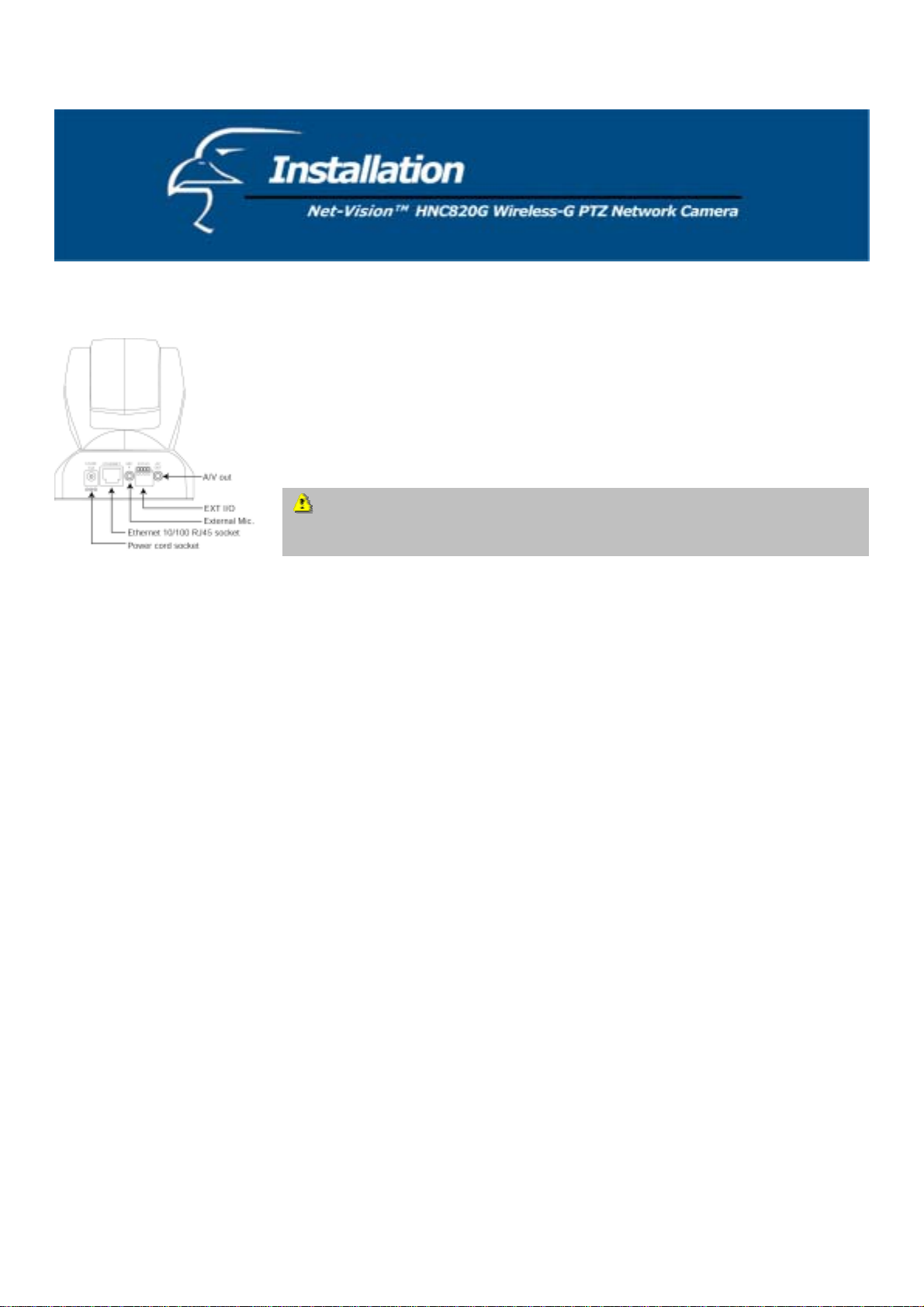
Hardware Installation
Please verify that your product package contains all the accessories listed in the
“Package Contents” section. You will likely need an Ethernet cable; the cable should
meet the UTP Category 5 specifications and should not exceed 100 meters in length.
To install via Ethernet, make sure the Ethernet cable is firmly connected to a switch,
router, or hub. After attaching the Ethernet cable, plug in the power adapter.
Connect the power adapter jack to the Network Camera before p lugging in to the
power socket. This will reduce the risk of accidental electric shock.
Upon powering up, the device runs through a self-te st procedure and the front LEDs will blink between gr een and red a
few times. If self-test passes, the LEDs will shu t off and the Network Camera will be on stand-by and ready for software
installation. If self-test fails the red LED will blink several times. Refer to Appendix A for troubleshooting.
The network camera will try and detect an Ethernet connection. If it does not find a wired Ethernet connection, the
camera will search for a Wireless LAN (or WLAN) connection. While the camera searches for and tries to connect to a
wireless access point or station, the camera’s red LED light will flash every second. Until the camera connects to another
wireless device, the red LED will remain lit. When operating in either wired or wireless netwo rk mode, the green LED
will flash every second as a heartbeat to indicate a link and activity.
To install in Ethernet
Make sure the Ethernet cable is firmly connected to a router or switch. After connecting the Ethernet cable, plug in the
power adapter. If the LED eventually becomes steady green after the se lf-test (about 1-1.5 minutes), go to the section
titled “Software Installation”. If Ethernet is not available, the camera will switch to wireless LAN mode.
To install in wireless LAN
If Ethernet is not available when the camera is powered, the camera will search for any access point with an SSID of
“default”. Once an access point is found, the LED will turn green to wait for installa tion. If the network environment
cannot match the default settings, install the camera via Ethernet and then proceed with the wireless LAN configuration.
7
Page 8

The Network Camera provides a general I/O terminal block with one digital input and one relay switch for device control.
Pin 1 and Pin 2 can be connected to an external senso r device and the state of voltage can be monitored fro m the initial
state 'LOW'. The relay switches Pin 3 and Pin 4 can be used to turn on or off an external device.
Consult with the dealer of the peripherals for correct installation.
1 DI+ INPUT (Max. 50mA, 12VDC)
2 DI- INPUT (Initial state of DI is Low)
3 SW_COMMON OUTPUT (open from SW_OPEN at initial state)
4 SW_NOPEN OU TPUT (Max. 1A, 24VDC or 0.5A, 125VAC)
8
Page 9
Software Installation
In this manual, "User" refers to anyone who has access to the network camera, and "Administrator" refers to anyone who
has access rights to configure the network camera and grant user access to it.
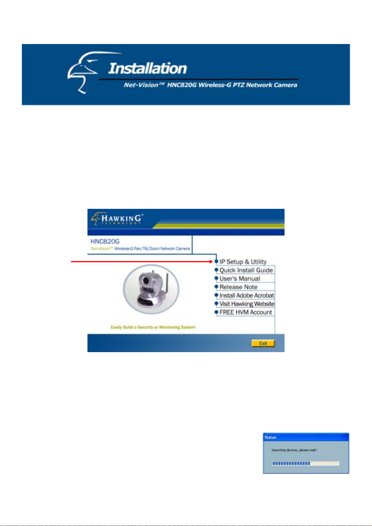
At the end of the hardware installation, the Administrator must insert the CD included with the package into the CD-ROM
drive of the PC. An auto-run program will appear (see below). If an auto-run window does not appear, go to the root
directory of the software CD and click on “autorun.exe”). Run the IP Setup progra m (see below) to locate the newly
installed network camera. To run, the IP Setup program, click on “IP Setup & Utility”. When the “IP Setup Wizard and
Management & Control Software” page appears, click on “IP Setup”.
On the packaging of the product, ben eath the UPC code, as well as on the lab el that appears on the pro duct, you will find a
sequence of four letters. Most Hawk ing netw ork ca meras with the sequ ence “H VVT” that are on standby awaiting so ftware
installation will be located by the IP Setup program. (Hawking network cameras with other four-letter sequences can be
located by installer programs that correspond to their respective sequences.) Therefore, there may be several entries shown
in the window. Administrators can differentiate between the network cameras by MAC Address (also listed as “Series
Number”) and click on the checkbox to the left of entries with the "Assigned" field labeled "No" to perform software
installation. The MAC Address is printed on t he label of the n et work cam era body.
Click on IP Setup to execute the installation program. The IP Setup program
will search for similar cameras on your local area network. A “similar”
camera will have the same “HVVT” code at the beginning of its serial
number. (The serial number is different from the series number/MAC
address.)
9
Page 10
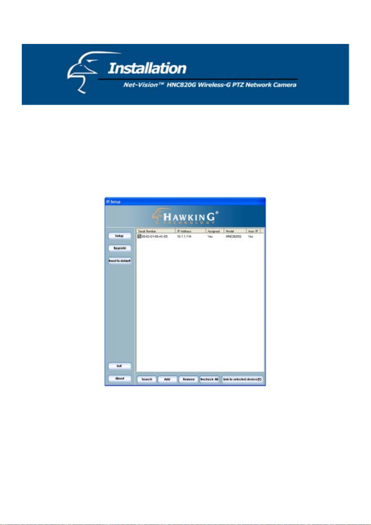
After completing the search, the main IP Setup window will appear. The IP Setup program should have returned an IP
address for your network camera (under the “Current IP Address” heading) that is consistent with your existing LAN
settings. The IP address will likely have been found by the DHCP server. (A DHCP server provides IP addresses to
client devices on the same network.) If there is no DHCP server, the camera will try to find a free IP address (this takes
from 15 second to 3 minutes, depending on the LAN status). The method that the IP Setup program uses to find an IP
address is to search from 192.168.0.99 to 192.168.0.254. If any of the addresses inside this range are free, the network
camera will be assigned one of these available IP addresses, and its subn et mask would be assigned to 255.255.255.0. I f
none of the addresses is free, the network camera will try the range from 192.168.0.2 to 192.168.0.98.
After an IP address
is assigned to the camera, the “Activity” status LED will start blinking.
In addition, the UPnP function will always assign an IP address to the network camera. The Administrator can click on
the button “Link to selected device” to connect to the camera via your web browser. If the camera does not appear on the
IP installer list, click on the “Search” button to search for the camera on the LAN.
If the IP Setup window still does not display any devices, you will need to find a tool small enough to be inserted into the
reset hole on the left side [if facing the front of the camera] of the base of the camera to reset the camera. Hold the button
for two full cycles. The two LEDs will flash continuously and stop twice. When the red LED begins to flash after the
second stop, release the button.
For detailed explanations of all of the IP Setup wizard’s various functions, it is highly recommended that you review the IP Setup wizard’s
manual, located on the CD that was included with the HNC8 20G’s pa ckaging.
10
Page 11
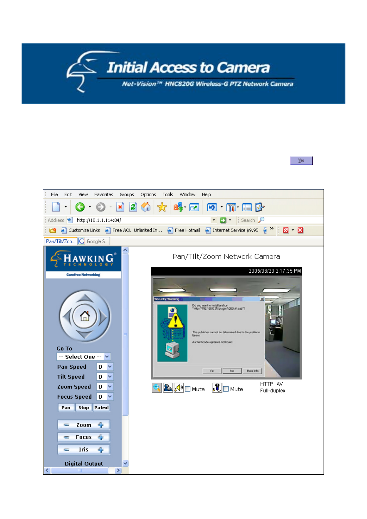
Installing the Plug-in
In Windows, during the initial access to the network camera, the web browser may prompt you for permission to install a
new plug-in for the network camera. Whether or n ot you are prompted to install the plug-in will depend on the Internet
security settings of your PC or notebook. (At higher levels o f security, the user may be prohibited from installing and
executing any plug-ins, even safe ones). This plug-in has been registered for certification and is used to display the
motion images in the browser. It is recommended that you proceed with the installation by clicking
. If the web
browser does not allow you to install the plug-in, check the In ternet security option to lower security levels, or contact
your network supervisor.
11
Page 12

Check Network Settings (even if the device is already connected)
Although the network camera may already be connected following the software installation procedure, administrators
should ensure that the network settings in the configuration page are correct, including the subnet mask, IP address of the
gateway, and DNS. If necessary, ask the network administrator or Internet service provider for specific information
regarding the network settings. By default, the network camera will require installation every time it reboots. If the
network settings are certain to work all the time, you can disable the install option. Refer to the “Network Settings”
section of this manual or the “Network” page of the web interface for details. If any of the settings are entered incorrectly
and the network camera is non-responsive or freezes as a result, you can easily restore the factory settings by following
the steps outlined in the “Troubleshooting” section of this manual.
Add a Password for Security
Since the administrator’s password is blank by default, the network camera will not ask for a password. However, it is
recommended that the administrator change the password to protect from network intruders. Once the administrator’s
password is saved, the network camera will require a user name and password for access. The administrator can establish,
at most, twenty user accounts. This enables each user to access the network camera. However, the user will still be
restricted from making changes to the system configuration. Critical functions, whose access is limited to administrators
only, include system configuration, user administration, and software upgrades. The administrator’s user name is
permanently assigned to “root”. Once the password is changed, the browser will display an authentication window to
ask for the new password.
Please Note: There is no way to access/view the administrator’s password. Therefore, if the password is forgotten, the
only solution is to restore the factory default settings.
12
Page 13
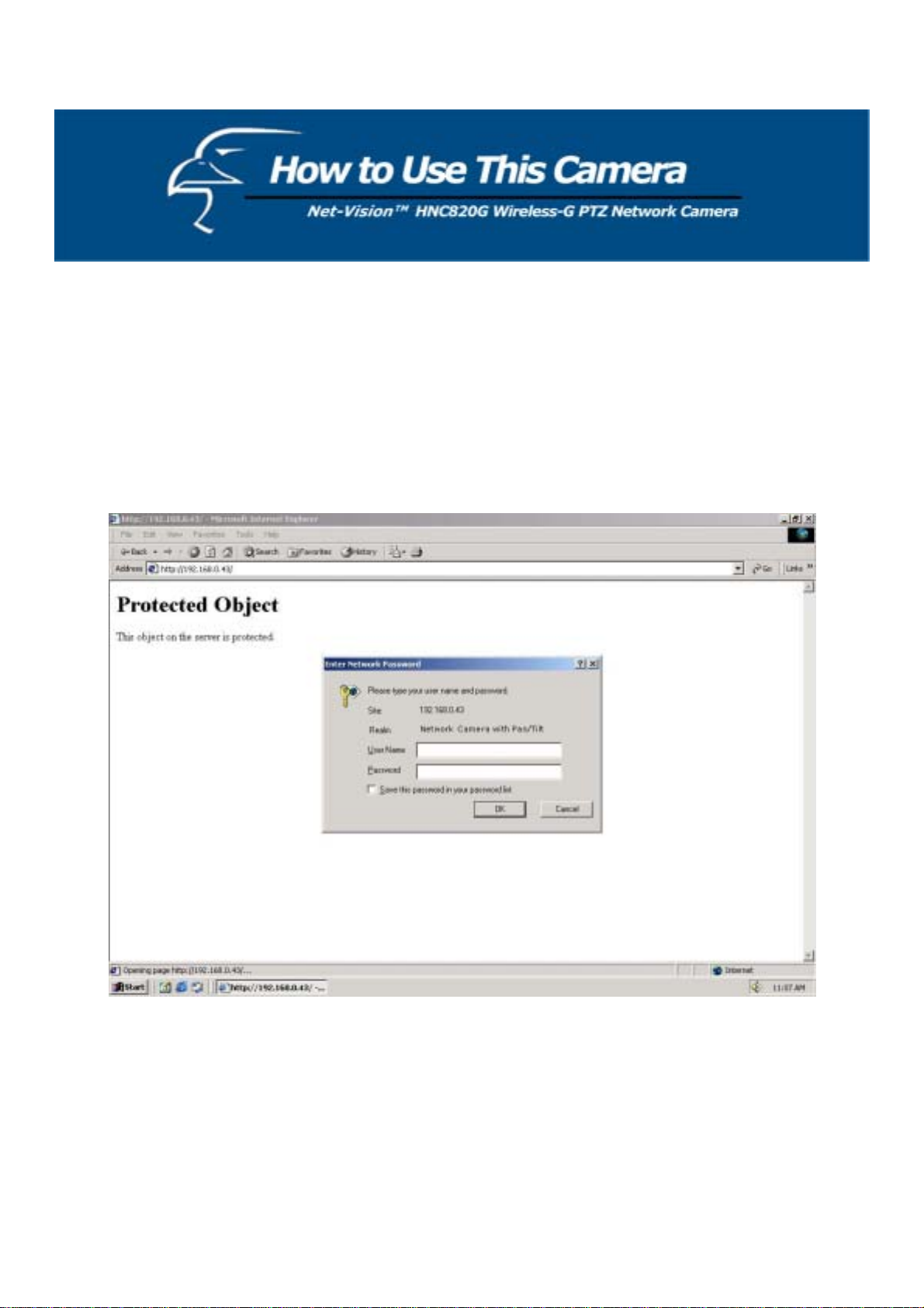
Authentication
After opening the Web browser and typing in the network camera’s IP address, a dialogue window may appear,
requesting a username and password, unless the administrator has not saved a password. Upon successful authentication,
the device’s main page will be displayed.
Again, the default Administrator user name is “root”, and the default Administrator password is blank.
In the figure below, the foreground is the login window and the background shows the message when authentication fails.
The user can check the option box at the bottom of the pop up window to save the password for future convenience.
13
Page 14
Primary User’s Capabilities
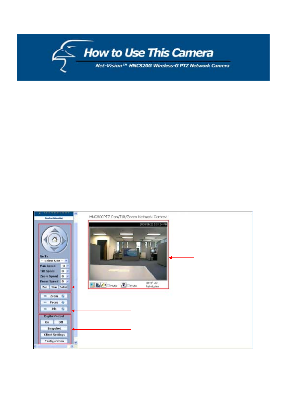
Main Screen with Camera View
The main page layout has three parts:
• Configuration functions: The camera can be configured via the user interfaces that can be obtained by clicking
on the buttons in the red box on the left-hand side of the figure below.
• Camera View: Displays what the camera sees (red box in the center of the figure below).
• Pan/Tilt/Zoom control buttons: These buttons provide a command interface to control the aim/physical
orientation and pan/tilt/zoom speeds of the camera.
• CCD control buttons: These buttons provide a command in terface to ad just the zoo m, focus, and iris control of
the camera.
Click on the configuration link (red box on the lower left side of the figure below) to enter the configuration page.
Camera View
Pan/Tilt/Zoom Control Buttons
CCD Control Buttons
Configuration Functions
14
Page 15
Configuration Controls
Digital Output
Click on the “On” or “Off” buttons to enable or disable the digital output.
Snapshot
Clicking on the “Snapshot” button will open a new window that displays a still image of the current camera view in JPEG
format.
Client Settings
Clicking on this button links you to the client setting pages. Please review the section that follows for more details.
Configuration
Only the Administrator can access camera configurations.
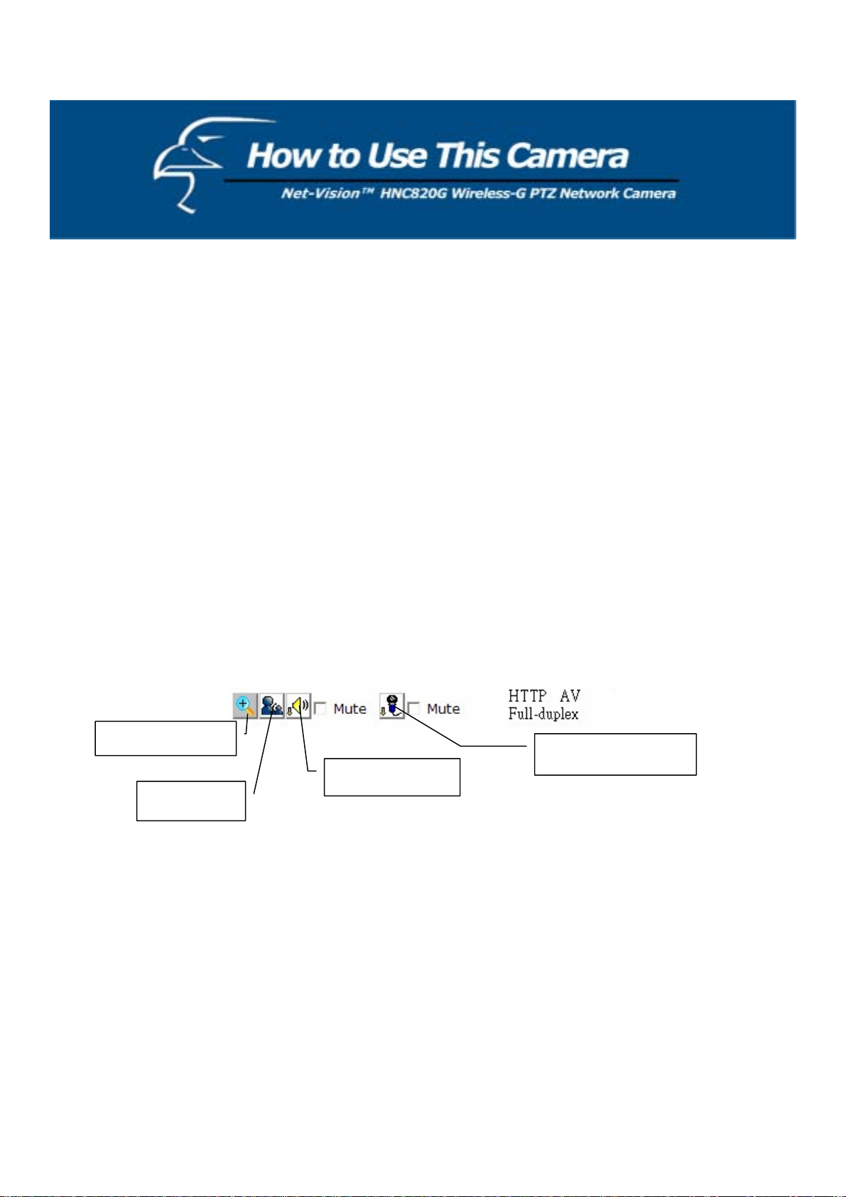
Camera V iew
The information bar at the top of the camera view display s: a. the assigned caption, and b. the current date/time. The
information bar at the bottom of the camera view displays: a. the current streaming mode, and b. audio transmission mode.
The user can push the talk button to talk to the remote server. The user can also adjust the volume of the speaker and
microphone.
Digital zoom
Speaker volume
Talk button
Microphone volume
The camera view not only provides live video, but also a w ay to aim the camera at different targets. The user can use the
mouse to click on areas/regions inside the camer a’s view; the camera will then pan and tilt accordingly to direct itself at
the selected target. The user can also scroll the mouse wheel up or down within the ca mera view to zoom in or out,
respectively.
15
Page 16

Pan/Tilt/Zoom Control Buttons
The directional buttons are for Left, Right, Up, Down, and Home. The Home button centers the camera.
Go to
Once the Administrator has determined the preset positions, users can direct the camera using this control.
Pan speed
This selection box sets the speed of the “Left” and “Right” controls.
Tilt speed
This selection box sets the speed of the “Up” and “Down” controls.
Zoom speed
This selection box s e ts the speed of the “z oom in” and “zoom out” controls.
Focus speed
This selection box sets the speed of the “focus” controls.
Auto pan
This button commands the camera to automatically pan from the current position to the left-most and then to the rightmost positions. After panning for a single cycle, the camera returns to the original position.
Auto patrol
This button commands the camera to automatically patrol between the preset positions on the Patrol List, which can be
modified on the “Camera control page”. After one patrol cycle, the camera returns to the original position.
Stop
This stops the “Auto Pan” or “Auto Patrol” command.
16
Page 17
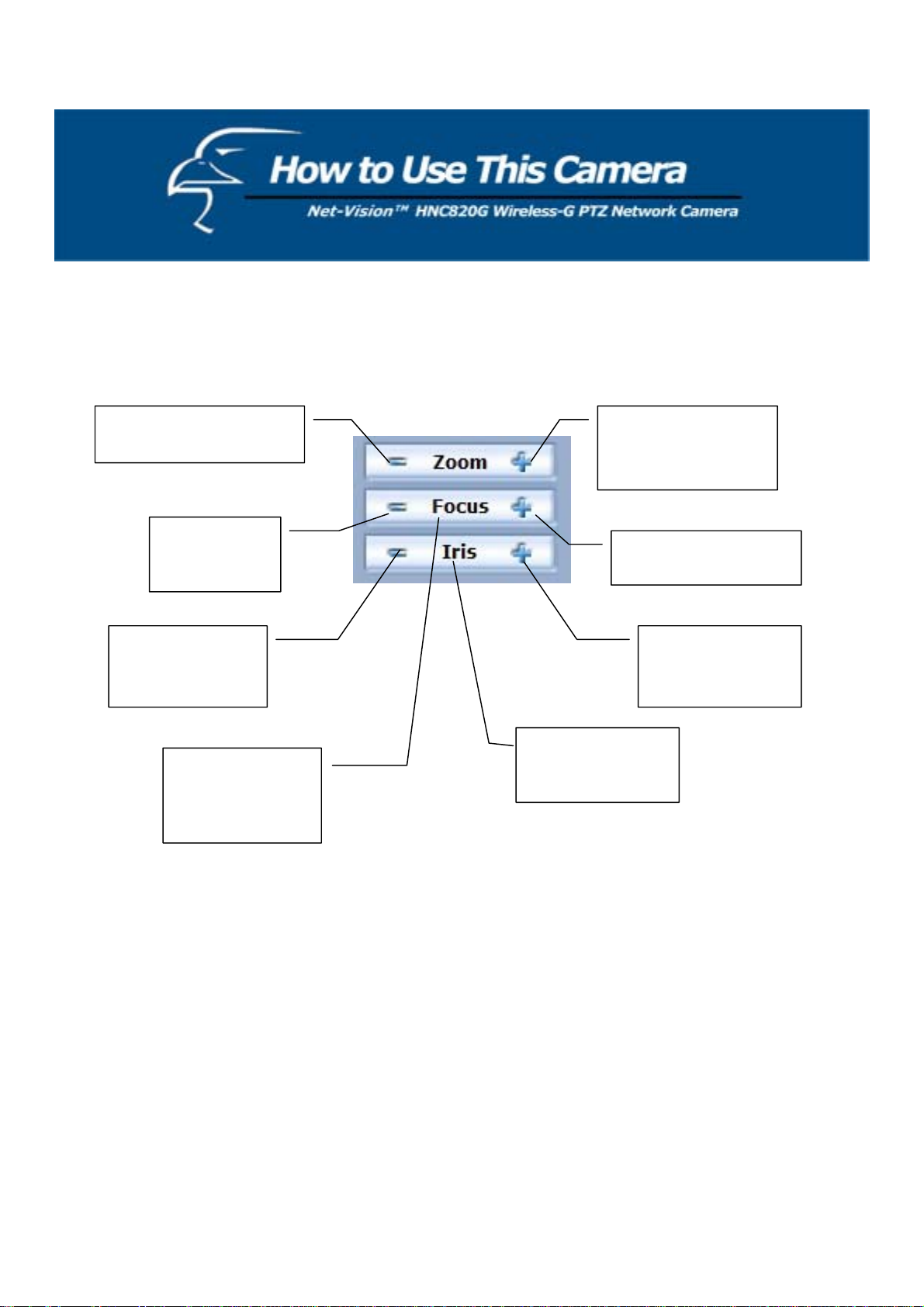
The CCD control buttons:
This set of buttons is used for adjusting the zoom, focus, and iris controls.
Click to zoom out for a
wider view.
Click to zoom in
telescopically for a
narrower view
Click to adjust
the focus.
Click to make the
IRIS smaller and
allow in less light.
Click to adjust the
focus.
Click to enlarge
the IRIS and allow
in more light.
The “Iris” buttons
The “Focus”
buttons allow the
allow the user to
adjust the auto Iris.
user to auto focus
the camera.
17
Page 18
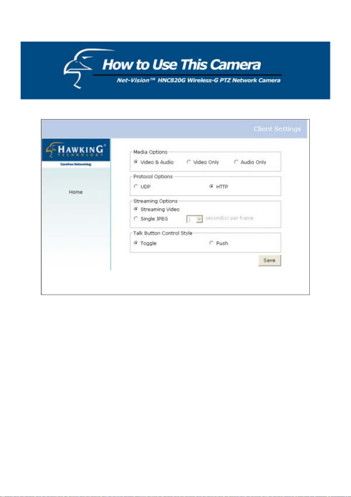
Client Settings
There are four settings within th e C lient Settings page.
Media Options - This is for the user to determine whether he/she wants to receive video, audio, or both.
Protocol Options - This allows the user to select the connection protocol between client and server. There are two
protocol choices to optimize usage: UDP and HTTP.
The UDP protocol allows for more real-time audio and video streams. However, some packets may be lost due to
network burst traffic and images may be obscured.
The HTTP protocol must be selected if the network is protected by a firewall and it only allows HTTP Port (80)
to be opened. In this mode, audio will not be sent and only video is operational. If there are no special
requirements, the UDP protocol is recommended. Generally speaking, the client’s preference should be in the
following order: UDP → TCP → HTTP. After the network camera is connected successfully, the “Protocol
Options” will indicate the selected protocol. The selected protocol will be recorded in the user's PC and will be
used for the next connection. If the network environment is changed, or the user wan ts to let the web browser
detect again, manually select the UDP protocol, save, and click HOME to re-connect.
Streaming Options - This allows users to select the type of video streaming. Select the “Streaming Video” option and
the video connection will enable you to view smooth, streaming video. The “Single JPEG” option, on the other hand,
will allow you to see still images of the video in JPEG format. There will be periodic client updates of the JPEG image
from the server, according to the “Frame rate” settings.
Talk Button Control Style – This allows the user to select either “click once and talk” or “push to talk”.
18
Page 19
Administrator’s Capabilities
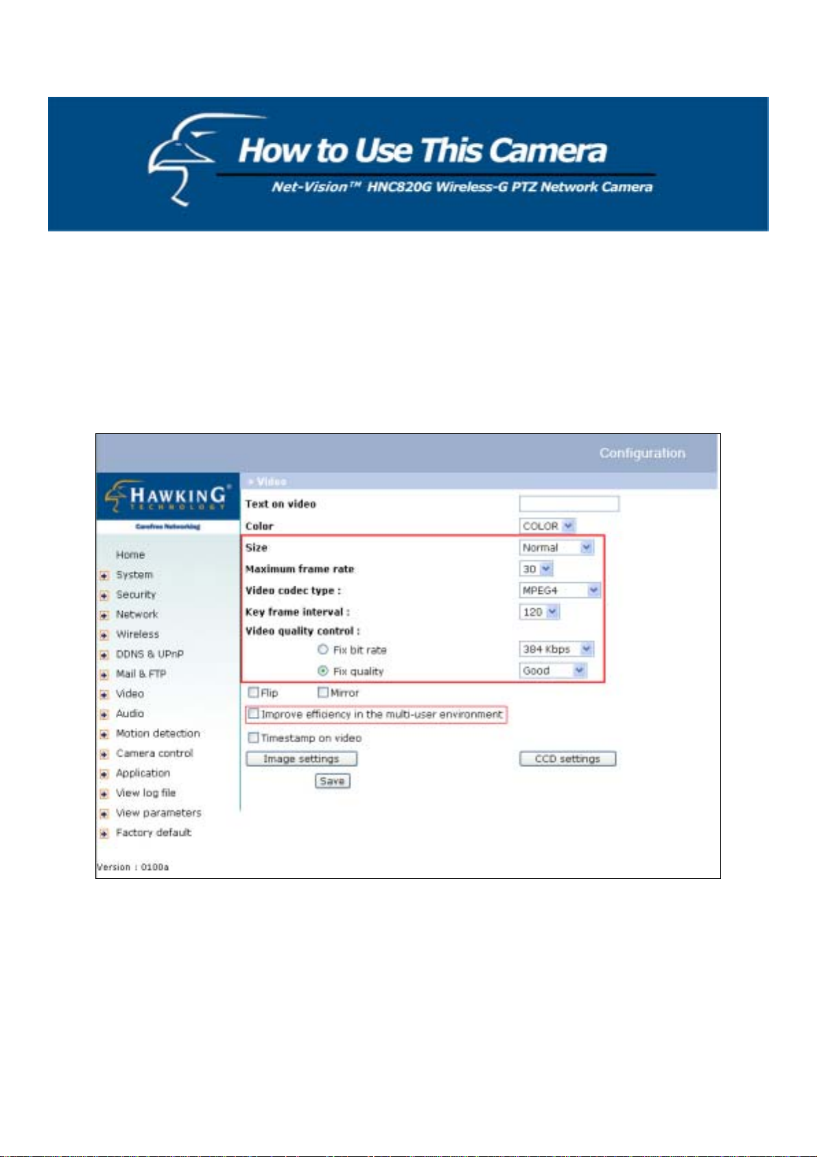
Configure for Optimal Performance
Optimal performance means obtaining the fastest image refresh rate and highest video quality, while utilizing the lowest
possible network bandwidth. Six items in the “Video” configuration page will control the performance: a. size, b.
maximum frame rate, c. video codec type, d. key frame interval, e. fix bit rate, and f. fix quality.
For Best Real-time Video Images
To achieve a good real-time visual effect, the network bandwidth should be large enough to allow a transmission rate of
greater than 20 image frames per second. If the broadband network is over 1 Mbps, set the “Fix bit rate” to 1000K bps or
1200Kbps, and set “Fix quality” at the highest quality. The maximum frame rate is 25 in the PAL system and 30 in the
NTSC system. (The PAL standard is used in Europe and China, and in parts of Africa, South America, and the Middle
East. The NTSC standard is used in the U.S., Canada, Japan, South Korea, and in parts of Central and South A merica.) If
your network bandwidth is more than 384Kbps, you can fix the bit rate according to your bandwidth and set the maximum
19
Page 20

frame rate to 25 fps or 30 fps. If you are shooting fast-moving images, you may w ant to slow the maximum frame rate
down to 20 fps in order to lower the rate of data transmission. This allow s for better video quality and the human eye
cannot easily detect the differences between those of 20, 25, or 30 frames per second. If your network bandwidth is below
384 Kbps, set the “Fix bit rate” according to your bandwidth and try to get the best performance by fine-tuning the
“Maximum frame rate”. In a slow network, greater frame rate results in blurred images. Another work-around is to
choose “Half” in the “Size” option for better images, or “Halfx2” for a larger image view. Video quality performance will
vary somewhat due to the number of users viewing on the network, even when the parameters have initially been finely
tuned. Performance will also suffer due to poor connectivity as a result of the netw o rk’s burst constraint.
In multi-user environments, users who are experiencing poor network performance will only receive key frames in
MPEG4 format. Reducing the key frame interval can improve the frame rate for poor network performance, but the
tradeoff is that network traffic will increase. If the camera’s webpage is open, check the “Improve efficien cy in the multiuser environment” box (see figure on previous page) to improve efficiency in multi-user environments.
For Best Quality Images
For the best video quality, you should set “Fix quality” at “Detailed” or “Excellen t” and adjust the “Maximum fra me rate”
to match your network’s bandwidth. If your network is slow and you receive “broken” pictures, go to the TCP protocol in
“Connection type” and choose a more appropriate mode of transmission. The images may suffer a time de lay due to a
slower connection. The delay will also increase as the number of users increases.
Compromise Between Real-time and Clear Images
If you have a broadband network, set “Fix quality” at ”Normal” or better, rather than setting “Fix bit rate”. You can also
fix the bandwidth according to your actual network speed and adjust the frame rate. Start from 30 fps down for best
results but not below 15 fps. If the image quality does not improve, select a lower bandwidth setting.
Select for Motion JPEG
The HNC820G features a dual video codec for both MPEG-4 and MJPEG compression formats. If MJPEG is selected,
the camera will transmit video data in JPEG format. This will require higher bandwidth to view smooth video. Generally
speaking, each normal-sized JPEG image should be 3k-12k bytes, depending on the selected video quality and content.
Together with the selected frame rate, the administrator can control the bandwidth of each connection.
20
Page 21

Opening Accounts for New Users
Protect the Network Camera Using Passwords
The network camera initially has no default password (i.e., it is blank). This means that initia lly anyone can access the
network camera (including the configuration section) as long as the IP address is known. It is necessary to assign a
password if other users will need to have access to the network camera. Type a new word twice in (1) to enable
protection. This password is used to identify the administrator. Then add an account with user name and password for
other users in (2). The network camera can provide ten a ccounts for your additional users. Each acco unt identifies the
access right rather than the actual visitor. This allows multiple visitors to share the same account. An option to access
DI/DO is provided for each account. Some users may need to be proh ibited from controlling your attached devices. The
“Camera control” option allows certain users to access the controls for the camera’s pan/tilt/zoom functions. The “Talk”
privilege allows certain users to send audio to the network camera. The “Listen” privilege allows certain users to listen to
audio that is picked up by the camera’s built-in microphone.
You may choose to delete users in (3).
More flexible options for viewers
If you want to have a guest account for viewers only, you just need to add a user without a password and disable all the
privileges. Use this account for users who you want to be able to access the camera’s video, but with no additional
privileges.
21
Page 22
Building a Multimedia Web Attraction Site
]
]
]
1
2
3
Demo on multiple sites – mid-scale service
The network camera can allow for ten visitors to view it online simultaneously. After installation, focus the network
camera on any object you choose, and tell the visitors to type in the IP address. Caution: You may want to maintain your
visitor’s list in the “Security” configuration page to block out unexpected visitors.
Product demo for e-business – Large-scale Service
If the number of visitors has exceeded the limit, the Network Camera can allow the extra viewers to see snapshots in
JPEG mode on the homepage. They will be still images and will be refreshed periodically and automatically.
22
Page 23

Click on “Client Settings” on the homepage.
1.
2. Select “Single JPEG” in “Streaming Options”.
3. Set the snapshot interval to refresh the still image automatically. The longer the snapshot interval, the better the
snapshot mode works for multiple viewers.
If you want to expand to allow more viewers, the host server should be able to handle large network traffic, which, in turn,
must handle the picture refreshing from the network camera.
If the web server space has FTP service, set the network camera up as an FTP client to upload the pictures. Access to the
network camera will be independent of the number of viewers and the picture quality will remain constant.
1. Click on “Configuration” on the homepage.
2. Click on “Mail & FTP” in the left column.
3. Fill in the FTP related settings including server, server port, user name and password, as well as the upload path if it
is specified by the web space.
4. Click on “Save”.
5. Click on “Application” in the left column.
6. Select the day or days of the week in the “Weekly schedule” during which you would like to upload the pictures.
7. Select “Sequential operation” and set the interval.
8. Unselect “FTP put snapshots with date and time suffix” as the upload method and click on “Save”.
9. The image file uploaded to the web space is named “video.jpg”. Check if the file is successfully uploaded to the
correct folder.
10. Prepare a homepage with the embedded image reference to the image file uploaded via FTP in advance.
23
Page 24
24
Page 25

If the web space has no FTP service, an auto-refresh homepage can be used to periodically poll the newest image from the
network camera. It is most efficient if using a free web space provider, as the FTP service may be limiting.
Prepare an auto-refresh homepage according to the following example:
The URL of the image is http://“IP address of the Network Camera”/cgi-bin/video.jpg. Set the IP address according to
your network camera. Define the refresh interval according to your network bandwidth for best results. If the refresh rate
is too fast and there are a large number of visitors, this may overload the network camera and slows the response.
The following is an example of an auto-refresh web page:
<html>
<head>
<title>Example - auto refresh</title>
</head>
<body>
<p align=left>
<font size="7" face="Comic Sans MS" color="#FF0000">
MiniAVServer Demo
</font>
</p>
<p align=left>
<!-- Begin of scripts to auto refresh the image. Change the IP address in the image URL and
refreshrate if necessary. //-->
<script language=javascript>
var image="http://19 2.168.0.203/cgi-bin/vi de o.jpg"; //IMAGE URL
var refreshrate=5; //SECONDS BETWEEN REFRESH
var imgwidth=352; //IMAGE WIDTH
var imgheight=240; //IMAGE HEIGHT
function refresh(){
document.images["pic"].src=image+"?"+new Date();
setTimeout('refresh()', refreshrate*1000);}
document.write('<img src="'+image+'" height="'+imgheight+'" width="'+imgwidth+'"
name="pic">');
if(document.images)window.onload=refresh;
</script>
<!-- End of scripts to auto refresh the image. //-->
</p>
</body>
</html>
25
Page 26

Building a Security Application
Note: For this section, please refer to the figure on Page 23.
The Administrator can combine options on the application page to perform many useful security applications. There are
two trigger sources coming from attached devices, such as for motion detection. There are also two kinds of actions
responding to such events, including uploading snapshots over the Internet and driving other attached devices. To upload
the snapshots, the User can choose either email or FTP according to user’s needs. Both e-mail and FTP use the network
settings on the Mail & FTP page. Refer to the definition section for detailed configuration.
1. Click on “Configuration” on the homepage.
2. Click on “Application” in the left column.
3. Check the weekdays as desired and give the period from "Snapshots begin" to "Snapshots end" to monitor the
triggering conditions every day.
4. Check the “Event operation” box. The triggering condition can be se t to detected motion or the status of the attached
device.
5. Set the delay before detecting the next event to avoid continuous false alarms following the or ig inal even t.
Send snapshots when motion is detected
If no external sensor is available, the Administrator can use the built-in motion detection to monitor any movement and
send snapshots via email for security check.
6. Click on “Motion detection” in the left column.
7. Check the “Enable motion detection” box at the top.
8. Click on “New” to have a new motion detection window to monitor video.
9. Type in a name to identify the new window.
10. Use the mouse to click, hold, and drag the window corner to resize it, or the do the same to the title bar to move the
window.
11. Fine-tune using the “Sensitivity” and “Percentage” fields to best suit the camera’s environment.
Higher ”Sensitivity” will help to detect even the slightest amount of motion. Higher “Percentage” discriminates
smaller objects. In other words, the higher the sensitivity, the more easily motion will be detected. The higher the
percentage, the more difficult it will be to detect small moving objects. (Therefore, by increasing the percentage,
you will be able to exclude minor, unnecessary motions, if des ired. )
12. Clicking on “Save” enable s the activity display (the lined column to the left of the “New” button). Green means the
motion in the window is under the watermark (threshold) set by the Administrator and red means it is over the
watermark (threshold).
13. Click on “Application” in the left column .
14. Check the motion detection window name you set in Step 9 in the “Trigger Condition” section.
15. Check “Upload snapshots while motion detected” if you prefer to upload the snapshots.
16. Check “Send snapshots by email” or “Send snapshots by FTP”.
17. Click on “Save” to validate.
26
Page 27

27
Page 28

Definitions in Configuration
Only the Administrator can access system configuration. Each category in the left column will be explained in the
following pages. The bold texts are the specific words/phrases on the Option pages. The Administrator may type the
URL below the figure to directly enter the frame page for configuration. To set certain options through the URL, read the
reference appendix for details.
<url> http://<Network Camera>/setup/config.html
<Network Camera> is the domain name or original IP address of the Network Camera.
<url> http://<Network Camera>/setup/system.vspx
<Network Camera> is the domain name or original IP address of the Network Camera.
28
Page 29

System Parameters
Host name: The text displays the title at the top of the main page.
Turn off the LED indicator: Check this option to shut off the LEDs. This can prevent the camera from being no ticed.
Automatically restore Digital Output (DO) state: The network camera will turn the DO on when events take place, if
the administrator has configured it properly in the Application page. Checking this option will restore the DO state to
“off” after the specified number of seconds.
Keep current date and time: Click on this to keep the network camera’s current date and time. An internal real-time
clock maintains the date and time even when the power of the system is turned off.
Sync with computer time: Synchronizes the network camera’s date and time with the local computer. The read-only
date and time of the PC is displayed as updated.
Manual: Adjust the date and time according to what is entered by the Administrator. Notice the format in the related
fields while doing the entry.
Automatic: Synchronize with the NTP server over the Internet when ever the Network Camera starts up. It will fail if the
assigned time-server cannot be reached.
NTP server: Assign the IP address or domain name of the time-server. Leaving the text box blank connects the network
camera to the defaul t time-servers.
Time zone: Adjust the time with that of the time-servers for local settings.
Update interval: Select hourly, daily, weekly, or monthly updates with the time on the NTP server.
Remember to click on
to immediately validate the changes. Otherwise, the correct time will not be synchronized.
29
Page 30

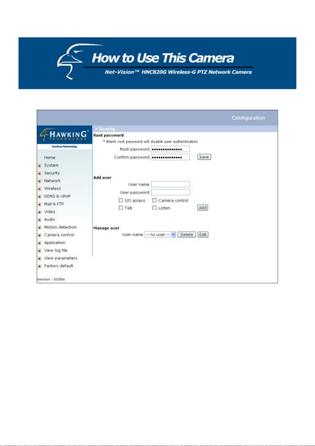
User Group Administration
Root password: The Administrator’s user name is “root” by default and cannot be changed. The Administrator’s
password is blank by default. Change the Administrator’s password by typing in the new password identically in both
text boxes. The typed entries will be displayed as asterisks for security purposes. After clicking
will ask the Administrator for the new password for access.
Add user: Type the new user's name and password and press to insert the new entry . The new user will be displayed
in the user name list. There is a maximum of twenty user accounts. Each user can have four privileges: "I/O access",
"Camera Control", “Talk”, and “Listen”.
“I/O access”: Allows the user to control the digital output (DO) and obtain the status of the digital input (DI).
“Camera control”: Allows the user to aim/direct the Network Camera at different targets.
“Talk”: Allows the user to talk to the server.
“Listen”: Allows the user to listen from the server.
Manage User:
“Delete user”: Pull down the user list to find a specific user name, and press
“Edit user”: Pull down the user list to find a specific user’s name, and press
privileges.
to complete.
to edit the user’s password and
, the web browser
30
Page 31

Edit User
Type the new password, change the privileges, and press
to modify the acc ount.
<url> http://<Network Camera>/setup/edituser. vspx
<Network Camera> is the domain name or original IP address of the Network Camera.
31
Page 32

Network settings
Any changes made on this page will restart the system in order to validate the changes. Make sure every field is entered
correctly before clicking on
"Get IP address automatically" & “Use fixed IP address”
The default status is “Get IP address automatically”. But this will require the user to perform the software installation
whenever the network camera starts, which can be tedious. Therefore, once the network settings have been entered
correctly (especially the IP address), select “Use fixed IP address” and the network camera will skip installation at the
next boot. The network camera can automatically restart and operate normally after a power outage. Users can run IP
Setup to check the IP address assigned to the network camera if the IP address is forgotten, or they can use the UPnP
function provided by the network camera (MS Windows XP provides the UPnP function at Network Neighborhood).
Regarding how to obtain the IP address automatically, please refer to the “Software Insta llation” section.
General
IP address: This is necessary for network identification.
Subnet mask: This is used to determine if the destination is in the same subnet. The default value is “255.255.255.0”.
Default router: This is the gateway used to forward frames to destinations in a different subnet. Invalid router settings
will cause transmissions to destinations in different subnets to fail.
Primary DNS: The primary domain name server that translates hostnames into IP addresses.
Secondary DNS: Secondary domain name server that backs up the Primary DNS.
HTTP
HTTP port: This can be something other than the default Port 80. Once the port is changed, the User must be notified of
the change for the connection to be successful. For instance, when the Administrator changes the HTTP port of the
network camera whose IP address is 192.168.0.100 from 80 to 8080, the User must type in the web browser
“http://192.168.0.100:8080” instead of “http://192.168.0.100”.
.
Streaming
“UDP Audio channel port” This can also be something other than the default port 5002, in order to work with the port
opened by the firewall.
“UDP Video channel port” This can also be something other than the default port 5003, in order to work with the port
opened by the firewall.
32
Page 33

<url> http://<Network Camera>/setup/network.vspx
<Network Camera> is the domain name or original IP address of the Network Camera.
Some invalid settings may cause the system to fail to respond. Change the configuration only if necessary
and consult with your network super visor or experienced users for c orrect settings. If the system loses
contact, refer to Appendix A for reset and restore procedures .
33
Page 34

Wireless
“SSID” (Service Set Identifier): This is the name that identifies a wireless network. Access points and wireless clients
attempting to connect to a specific WLAN (Wireless Local Area Network) must all use the same SSID. The default SSID
setting is “default”. Note: The maximum length of the SSID is 32 single-byte chara cters and the SSID cannot be any
of the space character or the following characters: “, <, >.
“Wireless mode”: Click on the pull-down menu to select from the following options:
“Infrastructure”: Makes the Network Camera connect to the WLAN via an Access Point. (This is the default
setting.)
“Ad-Hoc”: Makes the Network Camera connect directly to a host equipped with a wireless adapter in a peer-topeer environment.
“Channel”: While in infrastructure mode, the channel is selected automatically to match the channel setting for the
selected Access Point. In Ad-Hoc mode, the channel must be manually set to the same channel for each wireless adapter.
The default channel setting depends on the installed region.
“TX rate”: This field is for selecting the maximum transmission rate on the network. The default setting is “auto”,
meaning that the network camera will try to connect to other wireless devices with the highest transmission rate.
“Preamble” (either “Long preamble” or “Short preamble”): defines the length of the CRC block (Cyclic Redundancy
Check: a common technique for detecting data transmission errors) for communication between the Access Point and the
roaming wireless device. “Long Preamble” is the default setting. Note: High network traffic areas should use the shorter
preamble type.
“Data encryption”: Check the box to enable data encryption. It is disabled by default.
“Security”: Choose one of the following types of data encryption. By default, this field is set to “None”.
“None” – disables the data encryption.
“WEP” – uses WEP to encrypt the data.
“WPA-PSK” – uses a WPA pre-shared key to encrypt the data.
“Auth Mode”: Choose one of the modes below (“Auto” is the default setting; it is recommended that you leave it in this
mode):
“Auto”: The selection will apply the Shared mode authentication method. This is the strictest mode.
“Shared”: Allows communication only with other devices with identical WEP settings.
“Open”: Communicates the key across the network.
“Key length”: The administrator can select the key length among 64, 128, or 256 bits. 64-bit is the default setting.
“Key format”: Hexadecimal or ASCII. “HEX” is the default sett ing.
“HEX”: Characters consist of the numbers 0-9 and the letters A-F.
“ASCII”: is a code for representing English letters as numbers from 0-127. You will not be able to use the
following characters: “ < > or the space character. If you decide to change from Hex to ASCII, you will receive a
warning message that informs you that you cannot use these characters (with their Hex translations next to them
in parentheses).
“Network Key”: Enter a key in either Hex (hexadecimal) or ASCII format. When selecting different key lengths,
acceptable input length is listed as follows:
64-bit key length: 10 Hex digits or 5 ASCII characters.
128-bit key length: 26 Hex digits or 13 ASCII characters.
Note: When 22(“), 3C (<) or 3E (>) are input in the network key, the key format cannot be changed to ASCII format.
34
Page 35

<url> http://<Network Camera>/setup /wireless.vspx
<Network Camera> is the domain name or original IP address of the Network Camera.
35
Page 36

DDNS & UPnP
“Enable DDNS”: This option turns on the DDNS function.
“Provider”: The provider list contains four hosts that provide DDNS services. Please connect to the service provider’s
website to review the service charges.
“Host Name”: If the User wants to use a DDNS service, this field must be filled. Please input the hostname that is
registered in the DDNS server.
“Username/E-mail”: The Username or E-mail field is necessary for logging into the DDNS server or to notify the User
of the new IP address. Note: when this field is filled as “Username” the next field must be input as “Password”.
“Password/Key” Please input the password or key to access the DDNS service.
“Enable UPnP” This enables or disables the UPnP function. When UPnP is turned off, the camera cannot be found via
network neighbors in MS Windows XP. If the UPnP network component is installed in Windows XP, the hostname o f the
Network Camera will be shown with bracketed IP address in the Network n eighbors section. Ex: “Network Camera with
Pan/Tilt” (xxx.xxx.xxx.96). That is, the hostname of the Network Camera is “Network Camera with Pan/Tilt”, and the IP
address of the Network Camera is xxx.xxx.xxx.96 (depending on the last value of the IP address assigned to the Network
Camera).
“Save”: Click on this button to save the current settings for the DDNS service and UPnP function.
<url> http://<Network Camera>/setup/ddnsupnp.vspx
<Network Camera> is the domain name or original IP address of the Network Camera.
36
Page 37

Mail & FTP
SMTP
“1st SMTP (mail) server”: The domain name or IP address of the external email server .
“1st SMTP account name”: Account name on the email server.
“1st SMTP password”: Account password on the email server.
“1st recipient email address”: The email address of recipients for snapshots or log files. Multiple recipients must be
separated by semicolons ‘;’.
“2nd SMTP (mail) server”: The domain name or IP address of another email server once the previous server is
unreachable.
“2nd SMTP account name”: Account name on the backup SMTP server.
“2nd SMTP password”: Account password on the backup SMTP server.
“2nd recipient email address”: The email address of recipients for the backup server.
“Sender email address”: The return email address used in the event that the mails fail to send out.
FTP
Built-in FTP server port: This can also be something other than the default Port 21. The user can change this to a value
between 1 and 65535. After the change, the external FTP client program must change the server port of connection
accordingly.
1st FTP server: The domain name or the IP address of the external FTP server. The corresponding user settings below
must be correctly configured for remote access.
1st FTP user name: Assigned user name on the external FTP server.
1st FTP password: Assigned password on the external FTP server.
1st FTP remote folder: Assigned folder on the external FTP server. The string must conform to that of the external FTP
server. Some FTP servers cannot accept preceding slash symbols before the path without virtual path mapp i ng. Refer to
the instructions for the external FTP server for details. The folder privilege must be open for upload.
1st FTP passive mode: The network camera is located inside the network protected by a firewall; data connection for
FTP may be prohibited. By selecting passive mode, the FTP can bypass the rule and allow snapshot upload to proceed. If
the passive mode is selected, the network camera can automatically make an attempt for active mode, if the external FTP
server does not support passive mode.
2nd FTP server: The domain name or IP address of the external FTP server.
2nd FTP user name: Assigned user name on the backup FTP server.
2nd FTP password: Assigned password on the backup FTP server.
2nd FTP remote folder: Assigned folder on the backup FTP server.
2nd FTP passive mode: Passive mode setting for the backup FTP server.
37
Page 38

<url> http://<Network Camera>/setup/mailftp.vspx
<Network Camera> is the domain name or original IP address of the Network Camera.
38
Page 39

Video Codec Parameters
Text on video: The text will be displayed in the black bar above the video window with a timestamp. The timestamp is
captured from the date and time of the network camera that is maintained by a built-in real-time clock.
Color: Select either for color or monochrome video display.
Size: There are three options for two video sizes. “Half” is the quarter size of “Normal”. “Half x 2” has the same video
size as “Normal” but of a lesser quality, while consuming less network bandwidth.
“Video codec type”: The user can select either MPEG-4 or MJPEG. MPEG-4 is the default mode. In MJPEG mode, the
video frames are independent. In MPEG-4 mode, there are I frames and P frames. To decode a P frame the information of
previous frame is needed. MPEG-4 consumes much less network bandwidth than MJPEG.
There are five dependent parameters that can be adjusted for video performance.
Maximum frame rate: This limits the maximal refresh frame rate, which can be combined with the "Video quality
control" to optimize bandwidth utilization and video quality. If the User wants to fix the bandwidth utilization regardless
of the video quality, choose "Fix bit rate" and select the desired bandwidth. MPEG-4 video is composed of I frames and
P frames, as in the following sequence: IPPPPPIPPPPPIPPPP. “Key frame interval” determines how many repeated P
frames will appear after one I frame. A large “Key frame interval” can reduce the bit rate, but can also cause greater
image corruption if there is packet loss during transmission. The “Fix bit rate” and “Key frame interval” options are
only available in “MPEG-4” mode. The video quality may be poor due to a maximum frame rate within the limited
bandwidth of the network when images are moving rapidly. Consequently, to ensure detailed video quality (quantiza tion
rate) regardless of the network, it will utilize more bandwidth to send the maximum amount of frames when images
change drastically.
Flip: Vertically rotates the video.
Mirror: Horizontally rotates the video.
Check both options (Flip & Mirror) if the network camera is installed upside down.
“Improve efficiency in the multi-user environment”: Check this option to improve efficiency in a multi-user, lowbandwidth environment. Please note that this will cause each connection to slow once a connection has been established.
39
Page 40

<url> http://<Network Camera>/setup/video.vspx
<Network Camera> is the domain name or original IP address of the Network Camera.
40
Page 41

Image Settings
Click on “Image Settings” and a window will pop up that allows you to tune the "Brightness", “Contrast”, “Hue” and
"Saturation" for video compensation.
Each field has a range of eleven levels from -5 to +5. You can press “Preview” to help fine-tune the image. When the
image is at the desired quality, press “Save” to confirm the image settings. Click on “Restore” to recall the original
settings without incorporating the changes.
41
Page 42

CCD Settings
Click on “CCD Settings” and the CCD settings window will pop up.
By default, the CCD Setting is on auto-IRIS mode. Therefore the “Auto electronic shutter” (AES) option will be fixed at
1/60 (1/50) second. When the shutter is selected as “Auto”, the IRIS of the CCD will become fixed.
There are several selectable items for AES. A faster electronic shutter helps in viewing fast moving objects more clearly.
Checking “Low lux mode” helps in viewing objects in poorly lit areas.
When “Auto switch to B/W in low lux mode” is checked along with “Low lux mode”, the video will automatically
become black and white if the camera is in a darker environment.
Please note that the HNC800PTZ is not a night-vision or infrared camera, so it will not provide a good picture in total
darkness.
The “Enable BLC” option is for back light compensation (BLC). Normally, objects in front of a light source are difficult
to see. Thus, checking this option and adjusting the “BLC sens level” can help in viewing objects more clearly. The
BLC sens level pertains to the sensitivity of BLC d etection.
Click on “BLC Area Selection”, and a selection window will pop up. As the figure on the following page illustrates, the
video is divided into 48 rectangle areas of the same size. Select the areas in which you would like to enable BLC. If no
area is selected, checking the “Enable BLC” option will make no difference to the video.
42
Page 43

The picture above illustrates the corresponding areas of the selection window in the video window. “Select All” will
check all of the areas in the windows and “Clear All” will do the reverse. The “Save” button will confirm the selected
areas for BLC.
In the CCD settings window, click on “Preview” to see preview the video with the changed settings. Click on “Save” to
confirm the CCD settings. Click on “Restore” to recall the original settings without incorporating the changes.
43
Page 44

Audio
“Transmission mode”: There are five options to choose from. For all modes, only one client at a time can talk to the server
(camera).
“Full-duplex (Talk and listen simultaneously)”: In this mode, the User can talk to the server (camera) while l istening to the
audio from the server (camera) at the same time.
“Half-duplex (Talk or listen, not at the same time)”: In this mode, the User can talk to the serve r (camera) or list en from the
server (camera), but not at the same time.
“Simplex – Talk only”: In this mode, the User can only talk to the server (came ra).
“Simplex – Listen only”: In this mode, the User can only listen from the server (c amera).
“Disable”: In this mode, the audio is disabled in both directions.
“Send audio from the active client to all the other clients”: In half-duplex transmission mode, the user can select this option
to talk to the server and broadcast your voice to all the other clients.
“Improve audio quality in low bandwidth environment”: If the Network Camera works in versatile or low network
bandwidth environment, the User can check this option to improve a udio quality by sacrificing some real-tim e synchronization.
“Audio source”: Select source as either external or built-i n microphone.
“Acoustic echo cancellation”: In full-duplex m ode, the server can play sound fro m the client, a nd receive au dio from the
surrounding environment and send it to the client. Since the sound from the client is pla yed by the server, it wil l also be
received by the server’s microphone and sent back to the client. That is, the client will hear its echo. Selecting this option can
prevent echo by sacrificing the video frame rate.
“Bit rate”: There are three kinds of bit -rate for audio: 32Kbps and 24 Kbps are suitable f or b oth music and speec h-like audio,
while 8Kbps is suitable for only speech-like audio.
<url> http://<Network Camera>/setup/audio.vspx
<Network Camera> is the domain name or original IP address of the Network Camera.
44
Page 45

Motion Detection
Enable motion detection: Check this option to turn on motion detection.
Click on this
button to add a new window. At most, three windows can exist simultaneously. Use the mouse to
click, hold, and drag the window frame to resize it, or the title bar to move it. Clicking on the ‘x’ at the upper right-hand
corner of the window will delete the window. Remember to save in order to validate the changes.
Click on this
button to save the related window settings. A graphic bar will rise or fall depending on the image’s
motion variations. A green bar means the image variation is under the monitoring level threshold and a red bar means the
image variation is over the monitoring level threshold. When the bar goes red, the motion detection window will also be
outlined in red. Going back to the homepage, the monitoring window is hidden, but the red frame will show when motion
is detected.
Window Name: The text will show at the top of the window.
Sensitivity: This sets the allowable difference between two sequential images.
Percentage: This sets the space ratio of moving objects in the monitoring window.
A higher sensitivity and smaller percentage will allow easier motion detection. The following figure shows the screen
when
is clicked.
<url> http://<Network Camera>/setup /mo tion.vspx
<Network Camera> is the domain name or original IP address of the Network Camera.
45
Page 46

Camera Control
On the Camera Control page, there are two main function control areas:
Camera control area
The pan and tilt functions can be controlled with these buttons. The “Left”, “Right”, “Up”, and “Down” buttons aim the
camera accordingly. The “Home” button returns the camera to its default central po sition.
The “+” and “-” buttons on either side of “Zoom” control the zoom in and zoom out functions, respectively.
The “-”, “Focus”, and “+” buttons control the near focus, auto focus, and far focus functions, respectively.
The “-”, “IRIS” and “+” buttons make the aperture smaller, auto-IRIS and make the aperture larger.
“Pan speed”: This controls the speed of the horizontal movement of the camera. The greater the value, the greater the
speed when performing the “Left” or “Right” functions.
“Tilt speed”: This controls the speed of the vertical movement of the camera. The greater value, the greater speed when
performing the “Up” or “Down” functions.
“Zoom speed”: This controls the speed of the zoom function. The greater the value, the faster the zoom will change.
“Auto pan/patrol speed”: This defines the speed of auto panning and auto patrol. The greater the value, the faster the
speed.
Preset function area
“Current position”: If the User wants to save the current view as a preset location, he/she can enter a name for each of
the current video views in the “Current position” field and click on the “Add” button. The camera allows for ten preset
locations.
* The preset function is only valid in optical zoom mode.
“Preset position”: This keeps a list of the preset positions. Clicking on the “Delete” button will remove the selected
position from the preset list.
“Dwelling time”: The value set here specifies:
1. The stop time of each preset location during the camera’s auto patrol cycle.
2. The stay time at the left-most and right-most positions when the Network Camera is going through the auto-pan cycle.
“Enable IR control”: Checking this box allows the Administrator to enable the IR controller (remote control) to change
the direction of the camera. To allow controls only through URL commands or web pages, leave this box unchecked.
“Zoom times display”: Checking this box allows the Administrator to display the zoom magnitude on the transmitted
video. The information is described in the following table:
Text displayed Meanings
Zoom X3 3 times optical zoom; the focal lens equals 12.6 mm.
Zoom X10 xE2 10 times optical zoom; the focal lens equals 84 mm.
“Patrol selection”: After the User has saved a list of preset positions, the “Preset locations” box will also keep a list of
the preset positions. And once the “Select>” button is clicked, the “Selected location” box will keep a list of the patrol
stops. The “Remove” button removes a preset position from the patrol stops. The “UP”, “DOWN” buttons adjust the
order of the patrol stops. Several preset positions can be added to the patrol stops. The camera can accept up to 20 patrol
stops.
“Save”: This button is valid for “Pan speed”, “Tilt speed”, “Tilt speed”, “Auto pan/patrol speed”, “Enable IR control”,
“Dwelling time” and “Patrol selections”. In other words, after changing these settings, if the “Save” button is not clicked,
the new camera settings will not take effect.
46
Page 47

Camera control area
<url> http://<Network Camera>/setup /camctrl.vspx
<Network Camera> is the domain name or original IP address of the Network Camera.
Preset function area
47
Page 48

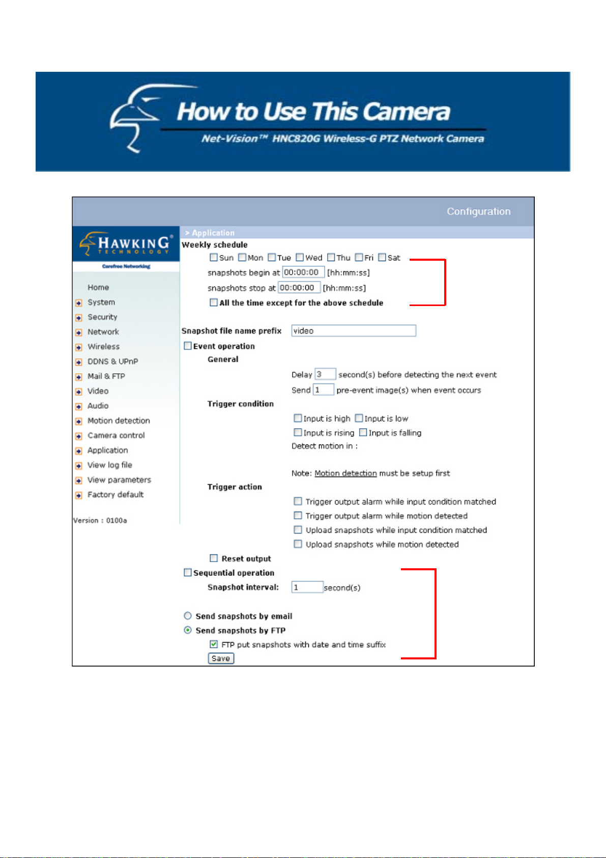
Application Setup
Weekly Schedule
Sun-Sat: Select the days of the week during which you would like to utilize the operations below.
Snapshots begin at: Set the time to start operations.
Snapshots stop at: Set the time to stop operations.
Setting identical begin and stop times means 24-hour operation.
“All the time except for the above schedule”: This inverts the selected schedule. This option is checked by default.
“Snapshot file name prefix”: This is where you can specify the prefix name for snapshot files. For example, if the prefix
name of the snapshot files is “joanne”, the snapshot file name will be joanne _20041116105638.jpg, which means the
snapshot was taken at 10:56:38, 2004/11/16.
Event operation
Delay _ second(s) before detecting next event: Set the time delay before restarting, to check on the triggering condition
when the current condition is triggered.
“Send pre-event image(s) when event occurs”: Specify how many pre-event snapshots will be sent if an event occurs.
Trigger condition: There are four conditions relative to the digital input and the three windows for motion detection.
More than one condition can be selected at once. Select the appropriate digital input condition that suits the
characteristics of the external device. “high”, “low” selects level-triggering via external voltage input. “rising”, “falling”
is for edge-triggering. There are three windows for motion detection and each can be assigned a name. If motion
detection has not been set up, it will not be shown. If this happens, click on “Motion detection” and a note will appear,
directing the User to the configuration page for motion detection.
Trigger action: There are four options for two types of actions. More than one condition can be selected at once. If you
choose to trigger an output alarm, the digital output will short both pins and complete the external device’s circuit. The
normal state is open. Either email or FTP can be used to command the uploading of snapshots. The snapshot names will
be “videopre.jpg”, “videotrg.jpg”, and “videopos.jpg”, respectively. They stand for the snapshots, before the event, right
upon the event, and after the event. The date and time suffix may also be added as an option. Confirm the external mail
or FTP server settings in the network configuration.
Reset output: Select and save this option to reset the external device at the digital output to return to the original state.
Sequential operation
Snapshot every _ second(s): The network camera will send snapshots at the specified intervals to the external server
using the method selected below. Remember: This operation is s t ill subject to the conditions set in the weekly schedule.
Send snapshots by email: This selects the uploading method following the intervals set above. The snapshot named
“video.jpg” will be attached in the email with the subject title “Periodic snapshots”.
Send snapshots by FTP: The snapshots will be uploaded to the external FTP server with the file name defined in the next
option. This can also be used to refresh the captured images stored in the external web server to build creative homepages.
FTP put snapshots with date and time suffix: This option sets up the snapshot capture date and time, which can be used
to easily differentiate the snapshot file names in either sequentially or by event operation. For instance,
“video@20040102030405.jpg” means the JPEG image was captured in the year 2004, January the 2
nd
, at 3 o’clock, 4
minutes, and 5 seconds. If this suffix is omitted, the file named “video.jpg” on the external F TP server will be refreshed
at the speci f ied interval.
48
Page 49

<url> http://<Network Camera>/setup/app.vspx
<Network Camera> is the domain name or original IP address of the Network Camera.
49
Page 50

Viewing Log File
Click on the link on the configuration page to view the system log file. The content of the file provides useful information
about configuration and connections after system boot-up.
Viewing System Parameters
Click on this link on the configuration page to view the entire system’s parameter set. The content is the same as those in
CONFIG.INI.
Factory Default
“Factory default”
Click on this link on the configuration page to restore the camera’s factory default settings. Any changes you have made
so far will be lost and the system will be reset to the initial factory settings. After clicking on the “Restore” button to
confirm, the system will restart and require the installer program to set the camera on the network again.
“Calibrate”
Recalibrate the home position to the default center to recover the tolerance caused by some external forces. This function
is the same as the “Center” button on the Remote Controller. Please note that confirmation message will appear after
clicking on the “Calibrate” button. The Network Camera will simply begin calibrating immediately.
50
Page 51

Remote Controller
The network camera comes with a remote controller to command its pan/tilt and other functions. The direction control
area provides the same functions as you find on the camera’s homepage. The Pan/Patrol/Stop functions are also the same
as on the homepage.
Direction control
area
Auto movement
control area
Auto Patrol: This button commands the camera to patrol between the preset positions on the patrol list that was set on the
“Camera control page”. After each patrol cycle, the camera stops at the original staring position.
Auto Pan: This button commands the camera to pan from the current position to the left-most or right-most positions and
back. After panning both vertical end positions, the camera would stop at the original starting position.
Center: This calibrates the camera’s position to aim at the center as the camera boots up.
Stop: This stops the auto movements (auto pan & auto patrol) of the camera.
51
Page 52

A. Troubleshooting
Status LED
After powering up, the network camera performs a self-diagnostic to detect any hardware defects. The following table
lists the LED patterns in general. In case of any fatal errors, the LED will blink in a pattern other than those below.
Condition LED Color
During self-diagnostic after power on Blinking in interchang ed green and red
Ethernet signal is lost Red LED is blinking until Ethernet is detected
Before network is setup Steady green until IP address is confirmed
After network is setup Blinks green every second
Any hardware failure Other patterns
Reset and Restore
On the left side (if facing it) of the camera there is a button hidden in
Restoring the factory defaults will
erase any previous settings. Reset or
restore the system after powering on.
the pinhole, as shown in the picture. It is used to reset the system or
restore the factory default settings. Sometimes resetting the system
sets the system back to its normal state. If the system problems remain
after reset, restore the factory settings and install again.
RESET: Insert a fine pen tip, paper clip, or similar object end to click
on the button.
RESTORE:
1. Insert a fine pen tip or paper clip and hold the button down.
2. Wait for the self-diagnostic to run twice.
3. Withdraw the pen tip, paper clip, or similar object as soon as the
second self-diagnostic starts.
52
Page 53

B. Frequently Asked Questions (FAQ)
Q What if I forget my password?
A After the Administrator's password has been assigned, all access to the network camera nee ds authentication. If you are
one of the managed users, you have to ask the Administrator for the password. If you are the Administrator, there is no
way to recover the root password except by restoring the factory default settings. Refer to Appendix A for the procedures.
Q Why can I not watch video from the network camera after it is authenticated?
A There are many possible scenarios regarding this problem:
1. If you have just installed the network camera and are unable to watch the video, check if the heartbeat LED is
blinking or the lens cap is off. If the heartbeat LED is dim, perform the software installation again.
2. If the network camera is well installed and you are accessing it for the first time using Internet Explorer, adjust
the security level of Internet Explorer to allow installation of plug-ins.
3. If the problem still exists after adjusting, and the message over the image wind ow is show ing "connecting ", the
network traffic may be too crowded.
4.
If only “A” is shown below the image (meaning for audio), check either of the media options that contain
“Video” in the client settings page.
Q What is the plug-in for?
A The plug-in provided by the network camera is used to disp lay motion pictures and audio in Internet Explorer. If your
system does not allow installation of any plug-in software, the security level of the web browser may need to be lowered.
It is recommended that you consult the network supervisors in your office regarding adjustment of the security level.
Software installation may be regulated in some offices.
Q Why is the timestamp different from the system time of my PC or notebook?
A The timestamp is based on the system time of the network camera. It is maintained by a real-time clock inside and can
be automatically synchronized with the time-server if the netwo rk camera is connected to the Internet and the function is
enabled. Differences of several hours may result from the time zone setting.
Q Can I install it on the ceiling?
A Yes. There are flip and mirror options in the video configuration page to correct the images for upside do w n installation.
Q The image is not clear enough.
A Adjust the “Focus” and “Zoom” to improve the image. You can also try to tune other video/image settings to achieve
the best visual effect. Also notice that the power line frequency must match the local utility to synchronize and minimize
the effect of flickering fluorescent lights.
Q Why does the image not refresh regularly?
A Some anti-virus programs filter the received web content. It takes time to perform data examination and affect
streaming applications such as that of the network camera. However, it only affects the HTP mode of the network camera.
If the network allows only HTTP mode, disable the web filtering function of the anti-virus program temporarily. During
this period, the User should be aware of the risk of malicious network activity.
53
Page 54

Q I have opened motion detection windows but they will not work.
A If the motion de tection windows are se t up and names are given, check to see if the functio n is checked on the first line.
While it is enabled, adjust the sensitivity and percentage to monitor the level indicator for best results.
Q I cannot hear any sound while watching.
A If only “V" is shown b elow the image, check the sound card in your PC and make sure the selected media option in the
client settings page contains audio. If "AV" is shown, check the audio source of the Network Camera to see whether you
are using the internal or external microphone.
Q How many users are allowed to watch the network camera at the same time?
A Too many users requesting the real-time multimedia content will jam the network. For best results, the ne twork camera
is designed to accommodate a maximum of ten (10) users to watch and listen at the same time. For a larger number of
users, it is recommended to build another web server to host the retrieved content from the network camera.
Q How fast is the video rate of the network camera?
A The MPEG-4 codec engine can process up to 30 frames per second internally. However, the total performance is
subject to many coefficients such as:
1. Network throughput
2. Bandwidth sharing
3. Number of users
4. The complicated/detailed objects and movement in view
5. The power of your PC or notebook computer that is responsible for displaying images.
On average, the transfer rate in a general local network environment can reach over 200 kilobytes per second and
approximately 10 to 20 pictures per second from a regular environment.
Q How can I keep the network camera as private as possible?
A The network camera is design ed for surveillance purposes and has many flexible interfaces. The user authentication
and special confirmation in installation can keep the network camera from unauthorized access. You may also change the
HTTP port to a non-public number. The demo account is good to separate guests from normal users, and thus, you can
easily block the guests anytime. You can check the system log to examine any abnormal activities and trace the origins.
Q Why can I not access the network camera when I set u p some options in the application?
A Any incorrect network settings will make the network camera inaccessible. If this happens, restore the factory default
settings following the procedures in Appendix A.
54
Page 55

C. Cleaning the Lens
The network camera has a high quality lens. When you need to clean the lens, please follow these instructions:
1. Prepare cotton swabs and alcohol.
2. Moisten the cotton swab with alcohol.
3. Gently clean the lens using the cotton swab.
4. If the lens is still dirty, repeat steps 2-3 until it is clean. Change to a clean cotton swab if the old one is dirty or
contains dirt that might scrape the lens. Never push hard on the lens or use a rough motion to clean it.
55
Page 56

D. Pan/Tilt/Zoom Data
z unit tilt angle: 0.918 degrees
z The tilt speeds of different auto pan/tile speeds.
1. auto tilt speed 1: 1.65 degree/sec
2. auto tilt speed 2: 6.59 degree/sec
3. auto tilt speed 3: 8.24 degree/sec
4. auto tilt speed 4: 10 .98 degree/sec
5. auto tilt speed 5: 16 .47 degree/sec
6. auto tilt speed 6: 32 .95 degree/sec
tilt speed
zoom times
-5 -4 -3 -2 -1 0 1 2 3 4 5
1~3 0.23 0.46 0.92 1.84 3.67 5.51 6.43 7.34 8.26 9.18 10.10
4~7 0.23 0.23 0.46 0.92 1.84 2.75 3.21 3.67 4.13 4.59 5.05
8~100 0.23 0.23 0.23 0.46 0.92 1.38 1.61 1.84 2.07 2.30 2.52
z unit pan angle: 1.29 degrees
z The pan speeds o f different auto p an/tilt speeds.
1. auto pan speed 1: 2.10 degree/sec
2. auto pan speed 2: 8.41 degree/sec
3. auto pan speed 3: 16.82 degree/sec
4. auto pan speed 4: 22.43 degree/sec
5. auto pan speed 5: 26.04 degree/sec
6. auto pan speed 6: 67.28 degree/sec
Pan
speed
-5 -4 -3 -2 -1 0 1 2 3 4 5
zoom times
1~3 0.32 0.65 1.29 3.88 7.75 11.63 15.50 19.38 23.26 25.84 28.42
4~7 0.32 0.32 0.65 1.94 3.88 5.81 7.75 9.69 11.63 12.92 14.21
56
Page 57

E. URL commands for the Network Camera
For some customers who already have their own web sites or web control applications, the Network Camera can easily
integrated through convenient URLs. This section lists the commands in URL format corresponding to the basic
functions of the Network Camera.
Overview
This section specifies the external HTTP based application programming interface. The HTTP based camera interface
provides the functionality to request a single image, to control camera functions (PTZ, output relay, etc.) and to get and
set internal parameter values. The image and CGI-requests are handled by the built-in Web server.
Style Convention
In URL syntax and in descriptions of CGI parameters, a text in italic within angle brackets denotes content that is to be
replaced with either a value or a string. When replacing the text string, the angle brackets will also be replaced. As an
example of how this is the description of the name for the server, <servername> is denoted in the URL syntax description
below, and is replaced with the string myserver in the URL syntax example, also below.
URL syntax is written with the word “Syntax:" followed by a box with the referred syntax, as seen below. The name of
the server is written as <servername>. This should be replaced with the name of the actual server. This can either be a
name, e.g., "mywebcam" or "thecam.adomain.net" or the associated IP number for the server, e.g., 192.168.0.220.
Syntax:
http://<servername>/cgi-bin/video.jpg
Description of returned data is written w ith " Return:" in bold face followed by the returned data in a box. All data
returned as HTTP formatted, i.e., starting with the string HTTP is line separated with a Carriage Return and Line Feed
(CRLF) printed as \r\n.
Return:
HTTP/1.0 <HTTP code> <HTTP text>\r\n
URL syntax examples are written with "Example:" in bold face followed by a short description and a light grey box with
the example.
Example: request a single snapshot image
http://mywebserver/cgi-bin/video.jpg
General CGI URL Syntax and Parameters
CGI parameters are written in lower-case and as one word without any underscores or other separators. When the CGI
request includes internal camera parameters, the internal parameters must be written exactly as they are named in the
camera or video server. The CGIs are organized in function related directories under the cgi-bin directory. The file
extension of the CGI is required.
Syntax:
http://<servername>/cgi-bin/<subdir>[/<subdir>...]/<cgi>.<ext>
[?<parameter>=<value>[&<parameter>=<value>...]]
57
Page 58

Example: Setting digital output #1 to high
http://mywebserver/cgi-bin/setparam.cgi?do1=h
Get Server Parameter Values
Note: This request require administrator access
Method: GET/POST
Syntax:
http://<servername>/cgi-bin/admin/getparam.cgi?[<parameter>]
[&<parameter>…]
Where the <parameter> should be <group>[_<name>] or <group>[.<name>] If you do not specify the any parameters,
all the parameters on the server will be returned. If you specify only <group>, the parameters of related group will be
returned.
When query parameter values, the current parameter values are returned.
Successful control requests returns parameter pairs as follows.
Return:
HTTP/1.0 200 OK\r\n
Content-Type: text/html\r\n
Context-Length: <length>\r\n
\r\n
<parameter pair>
Where <parameter pair> is
<parameter>=<value>\r\n
[<parameter pair>]
<length> is the actual length of content.
Example: request IP address and it’s response
Request:
http://192.168.0.123/cgi-bin/admin/getparam.cgi?network_ipaddress
Response:
HTTP/1.0 200 OK\r\n
Content-Type: text/html\r\n
Context-Length: 33\r\n
\r\n
network.ipaddress=192.168.0.123\r\n
Set Server Parameter Values
Note: This request require administrator access
Method: GET/POST
Syntax:
http://<servername>/cgi-bin/admin/setparam.cgi? [nosync=<value>&]<parameter>=<value>
[&<parameter>=<value>…][&return=<return page>]
parameter value description
nosync
0, 1 Specifies that there should be no sync (write) of the
corresponding configuration file on flash. If parameter is
58
Page 59

omitted, a sync write will occur.
(note: this parameter must be put at begin of parameter list)
<group>_<name>.
return
value to assigned Assign <value> to the parameter <group>_<name>..
<return page> Redirect to the page <return page> after the parameter is
assigned. The <return page> can be a full URL path or
relative path according the current path. If you omit this
parameter, it will redirect to an empty page.
(note: The return page can be a general HTML
file(.htm, .html) or a server script executable (.vspx) file. It
cannot be a CGI command. It cannot have any extra
parameters. This parameter must be put at end of parameter
list)
Example: Set the IP address of server to 192.168.0.123
http://myserver/cgi-bin/admin/setparam.cgi?Network_IPAddress=192.168.0.123
Available Parameters on the Server
Group: System
NAME VALUE DESCRIPTION
hostname
(r/w)
<text string shorter than 15
characters>
host name of server
0 Do not turn of the led indicator ledoff
(r/w)
date
(r/w)
1 Turn off the led indicator
<yyyy/mm/dd> year, month and date separated by slash.
<keep> keep date unchanged
<auto> Using NTP to sync date/time automatically
time
(r/w)
<hh:mm:ss> hour, minute and second separated by colon.
<keep> keep date unchanged
<auto> Using NTP to sync date/time automatically
ntp
(r/w)
timezone
<domain name or IP
NTP server
address>
-12 ~ 12 time zone, 8 means GMT +8:00
(r/w)
updateinterval
(r/w)
0 ~ 2147483 0 to Disable automatic time adjustment, otherwise,
it means the seconds between NTP automatic
update interval.
serialnumber
(r)
firmwareversion
(r)
restore
(w)
restart
(w)(restart)
(w)
(r)
supportscriptversion
(r)
<mac address> 12 characters mac address without hyphen
connected
<text string shorter than 39
characters>
The version of firmware, including model,
company, and version number
0 Restore the system parameters to default value.
The value will be valid after restart the server.
0 ~ 65535 Restart the server after <value> seconds.
<state>
H – NC connected with COMMON do<1~4>
L – NO connected with COMMON
<state>
H – NC connected with COMMON di<1~4>
L – NO connected with COMMON
<text string shorter than 10
The version of supported script/webpage
characers>
59
Page 60

scriptversion <text string shorter than 10
characers>
The maximum version of currently installed
script/webpage
Group: Security
NAME VALUE DESCRIPTION
username_<1~10>
(r/w)
userpass_<0~10>
(r/w)
userattr_<1~10>
(r/w)
<text string shorter than 15
characters>
<text string shorter than 15
characters>
[dido][|talk][|listen][|camctrl]
[|conf]
change user name.
change user’s password.
The UserPass_0 is root’s password.
change user’s privilege. The privilege can be the
combination of
dido – Permit I/O access
talk – Permit to talk to server
listen – Permit to listen from server
camctrl – Permit to do camera control
conf – Permit to change server’s configuration
usercount
(r)
1 ~ 11 The current account number on the server including
root.
Group: Network
NAME VALUE DESCRIPTION
resetip
(r/w)(restart)
1 enable to get ipaddress, subnet, router, dns1, dns2 from
DHCP server at next reboot
0 Using preset ipaddress, subnet, router, dns1, dns2
ipaddress
<IP address> IP address of server
(r/w) (restart)
subnet
<IP address> subnet mask
(r/w) (restart)
router
<IP address> default gateway
(r/w) (restart)
dns1
<IP address> primary DNS server
(r/w)
dns2
<IP address> secondary DNS server
(r/w)
smtp1
<domain name or IP address> primary SMTP server, max 40 characters
(r/w)
mailto1
<Recipient email address> mail recipient address, max 80 characters
(r/w)
mailuser1
(r/w)
mailpass1
<user account name on 1st
mail recipient address, max 63 characters
smtp server>
<user password for mailuser1> mail recipient address, max 15 characters
(r/w)
smtp2
<domain name or IP address> secondary SMTP server, max 40 characters
(r/w)
mailto2
(r/w)
mailuser2
(r/w)
mailpass2
<text string shorter than 80
mail recipient address, max 80 characters
characters>
<user account name on 2nd
mail recipient address, max 63 characters
smtp server>
<user password for mailuser2> mail recipient address, max 15 characters
(r/w)
returnemail
(r/w)
localftpport
<text string for return email
return email address, max 80 characters
address>
<number less than 65535> FTP port
(r/w)
ftp1 <domain name or IP address> primary FTP server
60
Page 61

(r/w)
ftpport1
(r/w)
ftpuser1
(r/w)
ftppass1
(r/w)
ftpfolder1
(r/w)
(r/w)
ftp2
(r/w)
ftpport2
(r/w)
ftpuser2
(r/w)
ftppass2
(r/w)
ftpfolder2
(r/w)
(r/w)
httpport
(r/w) (restart)
videoport
(r/w)
audioport
(r/w)
<number less than 65535> primary FTP port
<user account on 1st FTP
server>
<password for ftpuser1> password for primary FTP server, max 15 characters
<target folder on 1st FTP
server>
1 Enable passive mode of primary FTP server ftppassmode1
0 Disable passive mode of primary FTP server
<domain name or IP address> secondary FTP server
<number less than 65535> primary FTP port
<user account on 2nd FTP
server>
<password for ftpuser2> password for secondary FTP server, max 15 characters
<target folder on 2nd FTP
server>
1 Enable passive mode of primary FTP server ftppassmode2
0 Disable passive mode of primary FTP server
<number less than 65535> HTTP port
<number less than 65 535> video Channel port for UDP
<number less than 65535> audio Channel port for UDP
Group: Wireless (restart)
ssid
(r/w)
wlmode
(r/w)
channel
<text string shorter than 32
characters>
0
1 Adhoc mode
1 ~ 11 Channel number of USA and Canada
(r/w)
1 ~ 13 Channel number of Euro
10 ~ 11 Channel number of Spain
10 ~ 13 Channel number of France
1 ~ 14 Channel number of All
txrate
(r/w)
"NONE", "1M", "2M",
"5.5M", "11M", "6M",
"9M", "12M", "18M",
"24M", "36M", "48M",
"54M", "Auto" for 802.11g
user name for primary FTP server, max 63 characters
upload folder in primary FTP server, max 40 characters
user name for secondary FTP server, max 63 characters
upload folder in secondary FTP server, max 40
characters
SSID for wireless lan settings
<default>
Infrastructure mode
<6>
<6>
<10>
<10>
<6>
Transmit rate in Mbps
<Auto>
61
Page 62

Long Long preamble preamble
(r/w)
Short
Short preamble
1 Enable data encription encrypt
(r/w)
authmode
(r/w)
0
Auto Automatic mode
Open
Disable data encription
Open mode
Shared Shared mode
keylength
(r/w)
keyformat
(r/w)
keyselect
(r/w)
key1
(r/w)
(64, 128) for 802.11g Key length in bits
<64>
HEX
Key1 ~ Key4 will be represented in HEX format
ASCII Key1 ~ Key4 will be represented in ASCII format
1 ~ 4 Default key number
<1>
<text string shorter than 58
characters> (depends on
WEP key1 for encryption
<0000000000>
keyformat & keylength)
key2
(r/w)
<text string shorter than 58
characters> (depends on
WEP key2 for encryption
<0000000000>
keyformat & keylength)
key3
(r/w)
<text string shorter than 58
characters> (depends on
WEP key3 for encryption
<0000000000>
keyformat & keylength)
key4
(r/w)
<text string shorter than 58
characters> (depends on
WEP key4 for encryption
<0000000000>
keyformat & keylength)
domain
(r)
‘U’ for USA
‘C’ for Canada
Wireless domain
‘E’ for Euro
‘S’ for Spain
‘F’ for France
‘I’ for Isrel
‘A’ for All
Group: Video
NAME VALUE DESCRIPTION
text
(r/w)
(r/w) (restart)
<text string shorter than 15
characters>
0 MPEG4 codectype
1 MJPEG
enclosed caption
size
(r/w)
(r/w)
quality 0 fix bit rate
1 half
2 half x 2
3 normal
4 normal x 2
5 double
0 monochrome color
1 color
62
Page 63

(r/w) 1 fix quantization
quant
(r/w)
1 lowest quality of video
2 lower quality of video
3 normal quality of video
4 higher quality of video
5 highest quality of video
bitrate
(r/w)
64000 set bit rate to 64K bps
128000 set bit rate to 128K bps
256000 set bit rate to 256K bps
384000 set bit rate to 384K bps
512000 set bit rate to 512K bps
768000 set bit rate to 768K bps
1000000 set bit rate to 1000K bps
1200000 set bit rate to 1200K bps
maxframe
(r/w)
1 set maximum frame rate to 1 fps
2 set maximum frame rate to 2 fps
3 set maximum frame rate to 3 fps
5 set maximum frame rate to 5 fps
10 set maximum frame rate to 10 fps
15 set maximum frame rate to 15 fps
20 set maximum frame rate to 20 fps
25 set maximum frame rate to 25 fps
30 set maximum frame rate to 30 fps
1 flip image flip
(r/w)
0 normal image
1 mirror image mirror
(r/w)
0 normal image
Group: Audio
NAME VALUE DESCRIPTION
bitrate
(r/w)
8000 set bitrate to 8K bps
24000 set bitrate to 24K bps
32000 set bitrate to 32K bps
transfermode
(r/w)
0 Full-duplex (Talk & Listen simultaneously)
1 Half-duplex (Talk or Listen, not at the same time)
2 Simplex – Talk only
3 Simplex – Listen only
0 Do not send audio from active client to all other clients sendclientaudio
(r/w)
1 Send audio from active client to all other clients (only
possible in Half-duplex)
0 Use external microphone in source (r/w)
1 Use build microphone
0 Disable low bandwidth environment support lowbandwidth
(r/w)
1 Improve in low bandwidth environment
0 Disable enableaec (r/w)
1
63
Page 64

Group: Image
NAME VALUE DESCRIPTION
brightness
(r/w)
saturation
(r/w)
contrast
(r/w)
hue
<-5 ~ 5> Adjust brightness of image according to mode
settings.
<-5 ~ 5> Adjust saturation of image according to mode
settings.
<-5 ~ 5> Adjust contrast of image according to mode
settings.
<-5 ~ 5> Adjust hue of image according to mode settings.
(r/w)
mode
(w)
Preview Apply the parameter of image but not save
Restore Restore the last saved image parameters
Save Directly save the adjust image parameters
Group: Motion
NAME VALUE DESCRIPTION
0 disable motion detection enabled
(r/w)
1 enable motion detection
0 disable motion window #1 win<1~3>_enabled
(r/w)
win<1~3>_name
(r/w)
win<1~3>_left
(r/w)
win<1~3>_top
(r/w)
1 enable motion window #1
<text string shorter than 15
name of motion window #1
characters >
0 ~ 352 for CCD
Left coordinate of window position.
0 ~ 320 for CMOS
0 ~ 288 for PAL
Top coordinate of window position.
0 ~ 240 for
NTSC & CMOS
win<1~3>_width
(r/w)
win<1~3>_height
(r/w)
0 ~ 352 for CCD
0 ~ 320 for CMOS
0 ~ 288 for PAL
0 ~ 240 for
Width of motion detection window.
Height of motion detection window.
NTSC & CMOS
update
(w)
1 Update the above motion detection settings to
take effect
Group: DDNS
NAME VALUE DESCRIPTION
enable
0, 1 Enable or disable the dynamic dns.
(r/w)
provider
(r/w)
1 ~ 4 dyndns.org (dynamic)
dyndns.org (custom)
tzo.com
dhs.org
hostname
(r/w)
usernameemail
(r/w)
passwordkey
(r/w)
Text string shorter than 63
characters.
Text string shorter than 63
characters.
Text string shorter than 63
characters.
Your dynamic hostname.
Your user or email to login ddns service provider
Your password or key to login ddns service provider
64
Page 65

update
0, 1 Up date the abov e ddn s settings to take effec t
(w)
Group: UPNP
NAME VALUE DESCRIPTION
enable
0, 1 Enable or d isable the UPNP service.
(r/w)
Group: CAMCTRL
NAME VALUE DESCRIPTION
panspeed
-5 ~ 5 Pan speed
(r/w)
tiltspeed
-5 ~ 5 Tilt speed
(r/w)
zoomspeed
-5 ~ 5 Zoom speed
(r/w)
autospeed
-5 ~ 5 Auto pan speed
(r/w)
dwelling
0 ~ 9999 Time to dwelling when patrol
(r/w)
enableir
0, 1 Enable or disable the IR control
(r/w)
presetname_<0~9>
(r/w)
presetpan_<0~9>
Text string shorter than 30
The name of preset location
characters.
-127 ~ 127 The pan coordinate of preset location.
(r/w)
presettilt_<0~9>
-127 ~ 127 The tilt coordinate of preset location.
(r/w)
patrolname_<0~19>
(r/w)
Text string shorter than 30
characters.
The name of patrol location
Group: CCD
NAME VALUE DESCRIPTION
autoiris
0 or 1 set 1 to enable auto iris, set 0 to disable auto iris
(r/w)
irislevel
(r/w)
autoelectronicshutter
(r/w)
0~8 Set iris size, set bigger value to set bigger iris
size
0~7 Set electronica shutter speed. set 0 for auto
shutter, set 1 for fixed at 1/60 (1/50). Bigger
value, faster shutter.
lowluxmode
0 or 1 Turn off or on low lux mode
(r/w)
obwlowluxmode
(r/w)
enableblc
0 or 1 Turn off or on black/white video in low lux
mode
0 or 1 Disable or enable back light compensation.
(r/w)
blcsenslevel
0~7 Set back light compensation level
(r/w)
blcarea(0)
(r/w)
0~255 First row in BLC area. 0 to indicate disabling all
sub windows. 255 to indicate enabling all sub
windows.
blcarea(1)
0~255 Second row in BLC area.
(r/w)
65
Page 66

blcarea(2)
0~255 Third row in BLC area.
(r/w)
blcarea(3)
0~255 Fourth row in BLC area.
(r/w)
blcarea(4)
0~255 Fifth row in BLC area.
(r/w)
blcarea(5)
0~255 Sixth row in BLC area.
(r/w)
Drive the Digital Output
Note: This request requires the privilege of I/O access control.
Method: GET/POST
Syntax:
http://<servername>/cgi-bin/setdo.cgi?do1=<state>[&do2=<state>]
[&do3=<state>][&do4=<state>][&return=<return page>]
Where state is H, L. H means NC (normal close) connected with COMMON and L means NO (normal open) connected
with COMMON. The number of DO dependents on the server type.
parameter Value description
do<num>
<state>
H – NC connected with COMMON
L – NO connected with COMMON
return
<return page> Redirect to the page <return page> after the parameter is
assigned. The <return page> can be a full URL path or
relative path according the the current path. If you omit this
parameter, it will redirect to an empty page.
Example: Drive the digital output 1 to high and redirect to an empty page
http://myserver/cgi-bin/setdo.cgi?do1=H
Query Status of the Digital Input
Note: This request requires the privilege of I/O access control.
Method: GET/POST
Syntax:
http://<servername>/cgi-bin/getdi.cgi?[di1][&di2][&di3][&di4]
If no parameter is specified, all the status of digital input will be returned.
Return:
HTTP/1.0 200 OK\r\n
Content-Type: image/jpeg\r\n
Content-Length: <length>\r\n
\r\n
[di1=<state>]\r\n
[di2=<state>]\r\n
[di3=<state>]\r\n
[di4=<state>]\r\n
where <state> can be H or L.
Example: Query the status of digital input 1
Request:
http://myserver/cgi-bin/getdi.cgi?di1
66
Page 67

Response:
HTTP/1.0 200 OK\r\n
Content-Type: image/jpeg\r\n
Content-Length: 7\r\n
\r\n
di1=H\r\n
Capture Single Snapshot
Note: This request require normal user privilege
Method: GET/POST
Syntax:
http://<servername>/cgi-bin/video.jpg
Server will return the most up-to-date snapshot in JPEG format. The size and quality of image will be set according to the
JPEG settings on the server.
Return:
HTTP/1.0 200 OK\r\n
Content-Type: image/jpeg\r\n
[Content-Length: <image size>\r\n]
<binary JPEG image data>
Account Management
Note: This request requires administrator privilege
Method: GET/POST
Syntax:
http://<servername>/cgi-bin/admin/editaccount.cgi
?
method=<value>&user=<name>[&pass=<value>][&privilege=<value>]
[&privilege=<value>][…][&return=<return page>]
parameter value description
method
add Add an account to server. When using this method,
“username” field is necessary. It will use default value of other
fields if not specified.
delete Remove an account fro m server. When using this method,
“username” field is necessary, and others are ignored.
edit Modify the account password and privilege. When using this
method, “username” field is necessary, and other fields are
optional. If not specified, it will keep original settings.
username <name> The name of user to add, delete or edit
userpass <value> The password of new user to add or that of old user to modify.
The default value is an empty string.
privilege
<value> The privilege of user to add or to modify. The privilege can be
the addition of the following values. Ex: A user with DI/DO
access and listen privilege can be assigned privilege as
privilege=dido&privilege=listen.
dido DI/DO access privilege
listen listen privilege
67
Page 68

talk talk privilege
camctrl camera control privilege (support only on PT(Z) version)
conf configuration privilege
return <return page> Redirect to the page <return page> after the parameter is
assigned. The <return page> can be a full URL path or
relative path according the the current path. If you omit this
parameter, it will redirect to an empty page.
System Logs
Note: This request require administrator privilege
Method: GET/POST
Syntax:
http://<servername>/cgi-bin/admin/syslog.cgi
Server will return the up-to-date system log.
Return:
HTTP/1.0 200 OK\r\n
Content-Ty pe: text/plain\r\n
Content-Length: <syslog length>\r\n
\r\n
<system log information>\r\n
Configuration File
Note: This request requires administrator privilege
Method: GET/POST
Syntax:
http://<servername>/cgi-bin/admin/configfile.cgi
Server will return the up-to-date configuration file.
Return:
HTTP/1.0 200 OK\r\n
Content-Ty pe: text/plain\r\n
Content-Length: <configuration file length>\r\n
\r\n
<configuration data>\r\n
Upload File (firmware)
Note: This request requires administrator privilege
Method: POST
Syntax:
http://<servername>/cgi-bin/admin/upload.cgi
Post data:
file=<file name>[&return=<return page>]\r\n
\r\n
<multipart encoded form data>
68
Page 69

Server will accept the upload file named <file name> to be stored on the flash as “flash.bin” and return with <return page>
if indicated.
Camera Control
Note: This request requires camera control access privilege
Method: GET/POST
Syntax:
http://<servername>/cgi-bin/camctrl.cgi
? [move=<value>][&focus=<value>]
[&iris=<value>][&speedpan=<value>][&speedtilt=<value>][&speedzoom=<value>]
[&speedapp=<value>][&auto=<value>][&zoom=<value>][&return=<return page>]
parameter value description
move
home Move to camera to home positio n
up Move camera up
down Move camera down
left Move camera left
right Move camera right
speedpan -5 ~ 5 Set the pan speed
speedtilt -5 ~ 5 Set the tilt speed
speedzoom -5 ~ 5 Set the zoom speed
speedapp -5 ~ 5 Set the auto pan/patrol speed
auto
pan Auto pan
patrol Auto patrol
stop Stop camera
wide To zoom for larger view with current speed zoom
tele To zoom for farer view with current speed
focus
auto To do auto focus
far To focus on farer distance
stop To focus on nearer distance
iris
auto Let the Networ k Camera control iris size
open Manually control the iris for bigger size
stop Manually control the iris for smaller size
return <return page> Redirect to the page <return page> after the parameter is
assigned. The <return page> can be a full URL path or
relative path according to the current path. If you omit this
parameter, it will redirect to an empty page.
69
Page 70

Recall
Note: This request requires camera control access privilege
Method: G E T
Syntax:
http://<servername>/cgi-bin/recall.cgi
?
recall=<value>[&return=<return page>]
parameter value description
recall Text string less than 30
One of the present positions to recall.
characters
return <return page> Redirect to the page <return page> after the parameter is
assigned. The <return page> can be a full URL path or
relative path according to the current path. If you omit this
parameter, it will redirect to an empty page.
System Information
Note: This request requires normal user privilege
Method: GET/POST
Syntax:
http://<servername>/cgi-bin/sysinfo.cgi
Server will return the system information.
Return:
HTTP/1.0 200 OK\r\n
Content-Ty pe: text/plain\r\n
Content-Length: <system information length>\r\n
\r\n
Model=<model name of server>\r\n
HostName=<host name of server>\r\n
Location=<video on text of server>\r\n
[Preset<0>=<first preset location>\r\n]
[Preset<1>=<second preset location>\r\n]
[...]
PTZEnabled=<PTZ status>\r\n
Where the <PTZ status> is a 32-bits integer, each bit can be set separately as follow s:
Bit 0 => Support camera control function 0(not support), 1(su pport)
Bit 1 => Build-in or external camera. 0(external), 1(build-in)
Bit 2 => Support pan operation. 0(not support), 1(support)
Bit 3 => Support tilt operation. 0(not support), 1(support)
Bit 4 => Support zoom operation. 0(not support), 1(support)
Bit 5 => Support focus operation. 0(not support), 1(support)
Preset Locations
Note: This request requires administrator access privilege
Method: GET/POST
Syntax:
http://<servername>/cgi-bin/admin/preset.cgi?
[addpos=<value>][&delpos=<value>][&return=<return page>]
70
Page 71

parameter value description
addpos <Text string less than
Add one preset location to preset list.
30 characters>
delpos <Text string less than
Delete preset location from preset list.
30 characters>
return <return page> Redirect to the page <return page> after the parameter is
assigned. The <return page> can be a full URL path or
relative path according to the current path. If you omit this
parameter, it will redirect to an empty page.
71
Page 72

F. How to View Your Camera via the Internet
The steps outlined below will help you install your camera behind a router:
1. Camera Identification
Open the camera’s web page by typing its IP address in your web browser, and click on “System”. If you intend
to install multiple cameras, it is recommended that you give each camera a unique “Host name” in the field
provided.
2. Ensure that the Camera Has a Local IP Address
You will need a local IP address to insta ll the camera and to be able to view it within the local area network
(LAN). If you have already insta lled the camera, the n you will have already obtained a loca l IP address via the
IP Setup program or web browser. You can go back to the IP Setup program or the camera’s web page at any
time to change the camera’s IP address. On the camera’s web page, you can set the IP address under the heading
“IP Address” in the “Network” section. The camera settings must correspond with your network’s existing
settings. Please note that the “Default Router” is your router’s local IP Address.
72
Page 73

3. Opening Ports
You will need to open unique ports for each camera in order to be able to view them remotely over the Internet.
You will need to open these ports in the “Network” section of the camera’s homepage for two reasons: a. if you
need to use ports other than the default HTTP Port 80, UDP Audio Channel Port 5002, and UDP Video Channel
Port 5003, and b. when more than one camera is being installed on the network. (Note: The default ports are not
shown in the figure above.) Please note that if you are using only one camera, you can use the default ports
without having to open a second port. Please also n ote that wh en installing the camera behi nd a router, you will
need to open the corresponding ports (same as the open camera ports) on the router for remote viewing (i.e.,
over the Internet). In some instances when installing behind a router, Port 80 may not be available; please check
your network settings or with your ISP to confirm. In the “Network” section of the network camera’s homepage,
the “HTTP” and “Streaming” fields allow for the opening of ports for the network camera. This will permit
users’ routers to support multiple network cameras. By default, Port 80 (on the router) is always open for
network camera web server access. For each additional camera that you intend to install, to enable remote
viewing (and/or audio and controls), you will need to assign unique HTTP and Streaming ports.
73
Page 74

For example, assume that you have five network cameras that need to be installed and they have the following IP
addresses:
10.1.1.125
10.1.1.126
10.1.1.127
10.1.1.128
10.1.1.129
You can open the HTTP port for each network camera, from port 81 to Port 85, as illustrated below:
Internet Camera 1 – IP 10.1.1.125, second “Web Server” port 81
Internet Camera 2 – IP 10.1.1.126, second “Web Server” port 82
Internet Camera 3 – IP 10.1.1.127, second “Web Server” port 83
Internet Camera 4 – IP 10.1.1.128, second “Web Server” port 84
Internet Camera 5 – IP 10.1.1.129, second “Web Server” port 85
The default, Port 5002, is open for the “UDP audio channel port” and you can define additional ports similar to
the above. If you have five cameras, you will also need to open a UDP audio channel po rt for each camera. To
avoid confusion with the “Video channel port”, please choose port n umbers that have sufficient gaps between
them and previously chosen port numbers. For example, if the first network camera has port numbers 5002 and
5003 open for the “Audio channel port” and “Video channel port”, respectively, you may want to choose p orts
5012 and 5013 for the same channels of a second network camera. The example below illustrates how you
might open the “UDP audio channel ports” for five cameras:
Internet Camera 1 – IP 10.1.1.125, “Control channel port” 5012
Internet Camera 2 – IP 10.1.1.126, “Control channel port” 5022
Internet Camera 3 – IP 10.1.1.127, “Control channel port” 5032
Internet Camera 4 – IP 10.1.1.128, “Control channel port” 5042
Internet Camera 5 – IP 10.1.1.129, “Control channel port” 5052
Use a similar method to assign ports for the “Video channel port”.
To view the camera over the Internet, you will need to configu re your router for Port Mapping. The router’s
user manual will include instructions on how to do this. The remainder of Appendix D. will also inc lude basic
setup instructions on how to view the camera via the Internet. Please remember that for multiple cameras, you
will need to open multiple ports per camera on your router: a. the HTTP port, b. the UDP audio channel port,
and c. the UDP video channel port.
Save/Cancel:
After making sure that all settings in the “Network” section of the network camera’s webpage are correct, click
on the “Save” button to store the settings for the network camera.
Steps 4 and 5 are applicable to any router you may have installed on your network.
74
Page 75

4. Locate, Make a Note of Your Router’s WAN (Public) IP Address
You will need to go to the router’s web page (by typing in its local IP address in the web address bar) and find
the “Status” (or similar) page. On this page, you should be able to locate the router’s IP address. This IP
address is the router’s public IP address and will be different from its local IP ad dress. You will use this public
IP address when enabling your camera to be viewed over the Internet. To view your camera remotely via the
Internet, it is recommended (but not required ) that y ou assign a sta tic IP address to yo ur rou ter. Yo u will need to
contact your ISP to obtain a static IP address. When the camera is attached to the router, the static IP address
will allow you to view the camera over the Internet. If you intend to view your camera from a remote location, it
is recommended that, in a secure location, you make a note of this IP address for future reference. It is still
possible to view your camera over the Internet with a dynamic IP address for your router, but this is not the
preferred method. With the dynamic option, your router’s IP address will change periodically. Therefore, when
the router’s IP address changes, unless y ou intend to check the router’s “Status” page regularly or you (and all
authorized viewers) know the router’s IP address at all times, you will not be able to view the camera over the
Internet. (With the dynamic option, only the router’s public IP address will change. The local IP address will
remain the same. Therefore, you will still be able to access the camera and a ll other clients on the local area
network from within the network. If your router’s public IP address is dynamic, you can also sign up for a
DDNS service that will keep the domain name constant.)
75
Page 76

5. Use Port Mapping to Assign Virtual Server Ports
Typically, there is an “Advanced Setup” (or similar) section on the router’s web page where you can find a
“Virtual Server” or “Port Mapping” sub-section. To enable remote viewing over the Internet for your camera,
you will need to open virtual server ports on your router. The steps outlined below should be similar for most
routers:
i. Once you have located the “Virtual Server” (or similar) section, select the “By Port” method if
this option is available.
ii. Select “TCP” in the “Port Type” field.
iii. Next, select “Single” if a “Single/Range” option is available. This is so that you can open
individual ports rather than a range of them.
iv. In the “Port Number” field, enter “Port 80 to Port 80” if you intend to you use the camera’s
default port settings (discussed earlier in this Appendix). If you do not intend to use the default
settings, or if you will be using multiple cameras, you will need to enter a different port number
(i.e., 83, 84, etc.). The “Port Number” field, for example, will then read “Port 83 to Port 83”, etc.
In this case, the private Port 83 will now be opened as a pub lic port. Please make sure that the
public and private ports match (i.e., Port 83 to Port 83). Please also re member that for multiple
cameras, you will need to open multiple ports for each camera (as discussed earlier in this
Appendix). Therefore, for the camera for which you just opened Port 83, yo u will also need to
open ports such as Port 5033 (Video channel), and Port 5032 (Audio channel). For example, in
the “Port Number” field, enter “Port 5033 to Port 5033”.
v. After opening each port, click on “Add” (see figure on previous page).
76
Page 77

6. Viewing the Camera from Outside the Network
Once the settings have been correctly entered and saved, authorized users can access the camera from outside the
local area network as well as from within. To access the camera from outside the local area network in a remote
location via the Internet, type (in sequence) the router’s public IP address, a colon, and the port number assigned
to the camera, in the address bar of y our web browser. For example, if your router has a public IP address o f
“64.82.99.33”, you would type the following into the address bar (assuming you assigned Port 85 to the camera):
“http://64.82.99.33:85”. From within the network, you would still use the camera’s local IP address to access
the camera. For example, if you were using the local IP address “10.1.1.129” for the camera, from within the
network you would now simply type: “http:// 10.1.1.129:85”. The “:85” is added at the end because y ou are
now using a port number other than the default Port 80. (Although, typing in the router’s p ublic IP address,
followed by a colon and port number, would work as well.)
77
Page 78

G. Technical Specifications
System
CPU: Trimedia PNX1300
RAM: 16MB SDRAM
ROM: 4MB FLASH ROM
Networking
Protocol
- TCP/IP, HTTP, SMTP, FTP, Telnet, NTP, DNS, uPnP, DDNS, and DHCP
Physical
- 10BaseT Ethernet or 100BaseT Fast Ethernet
Wireless LAN
- 2.4GHz 802.11g/b
- 54/48/36/24/18/12/9/6/11/5.5/2/1Mbps
Coverage:
- 54Mbps:64m, 48Mbps:70m,
- 36Mbps:80m, 24/18/12/9/6Mbps:120m,
- 11Mbps:80m, 5.5Mbps:120m
- 2Mbps:200m, 1Mbps:300m
Video
Algorithms Supported
MPEG-4 SP
MJPEG (selectable)
Features
- Adjustable image size, quality and bit rate
- Timestamp and text overlay
- 3 motion detection windows
Resolution
- Up to 30/25 frames at 176x120 or 176x144
- Up to 30/25 frames at 352x240 or 352x288
- Up to 15/12 frames at 704x480 or 704x576
Camera Specification
- 1/4 inch color CCD sensor
- Typical: 1.5 Lux / F1.8
- Low lux mode: 0.05 Lux/F1.8
- AGC, A WB
- Electronic shutter: 1/60 (1/50) to 1/120,000 sec
Lens
- Focal length 4.2 - 42mm
- Aperture F1.8 - 2.9
- 10X optical zoom
- 10X digital zoom
78
Page 79

Audio
- 32Kbps, 24Kbps, 8Kbps
- Acoustic echo cancellati on
- Full duplex audio communication
Microphone
- Omni-directional
- Frequency: 20 – 20,000Hz
- S/N ratio: more than 58dB
General I/O
- 1 sensor input(max. 12VDC 50mA)
- 1 relay output(max. 24VDC 1A, 125VAC 0.5A)
LED indicator
- Dual color system status indicator
Dimension
- 104.5mm(L) * 104.5mm(W) * 127mm(H)
Weight
- NET. 450g
Power
- Consumption: max. 12W
- Universal switching power-supply included
- Adapter input: 100-240VAC, 50/60Hz, 0.4A
- Adapter output: 12V DC, 1.5A
EMI & Safety
- CE, FCC
Operating Environment
- T emperature: 0-40°C/32-104°F
- Humidity: 85%RH
Viewing system requirement
Operating System
- Microsoft Windows 98SE/ME/2000/XP
Browser
- Internet Explorer 5.x or above
79
 Loading...