

Page 1
1 1
Page 2

Step 1: Check Contents & Installation Requirements 3
Step 2: Physical Description 8
Step 3: Hardware Installation 9
Step 4: Run the IP Setup Program 10
Step 5: Viewing & Tips 17
Appendix 18
2
Page 3
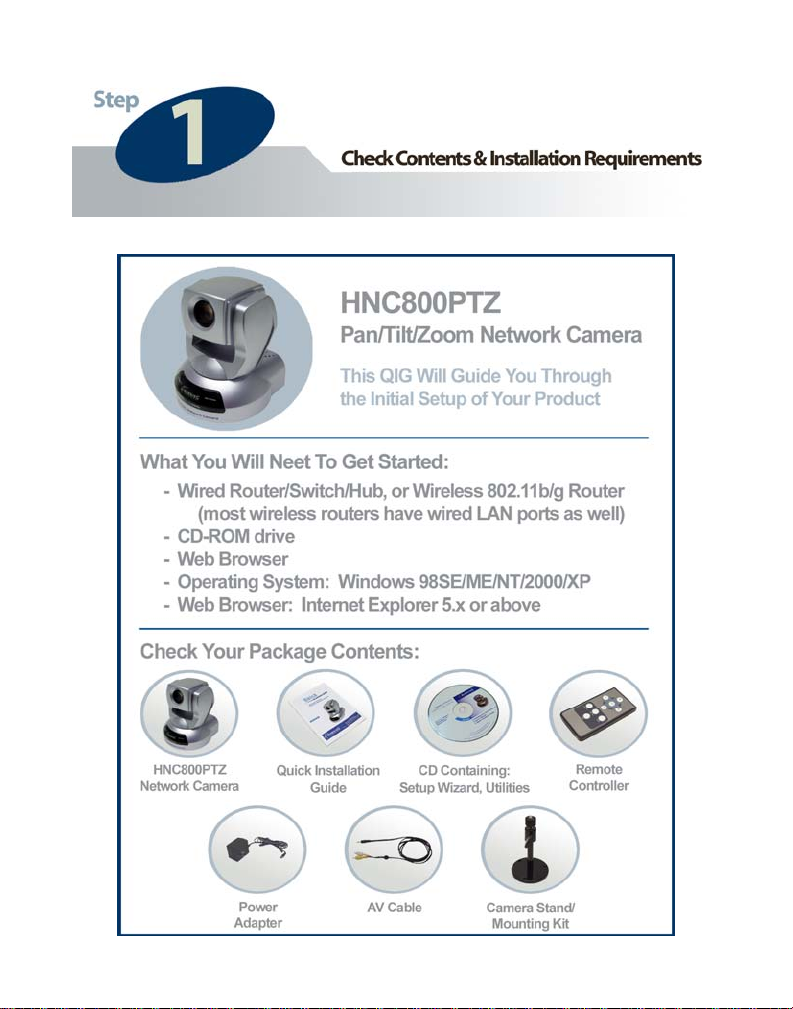
Congratulations on the purchase of your new Hawking Net-Vision
TM
HNC800PTZ Pan/Tilt/Zoom Network Camera. The HNC800PTZ is a
high performance stand-alone camera system that provides an ideal
solution for remote monitoring, surveillance, or sending live video over
the Internet. With pan, tilt, and 10x optical zoom capabilities, along with
many other advanced features, the HNC800PTZ is an excellent addition
to any security or monitoring system. The camera offers a broad array of
applications and can be used to monitor homes, offices, banks, schools,
childcare centers, hospitals, and other industrial and public areas. Please
read this quick installation guide carefully before beginning your
nstallation.
i
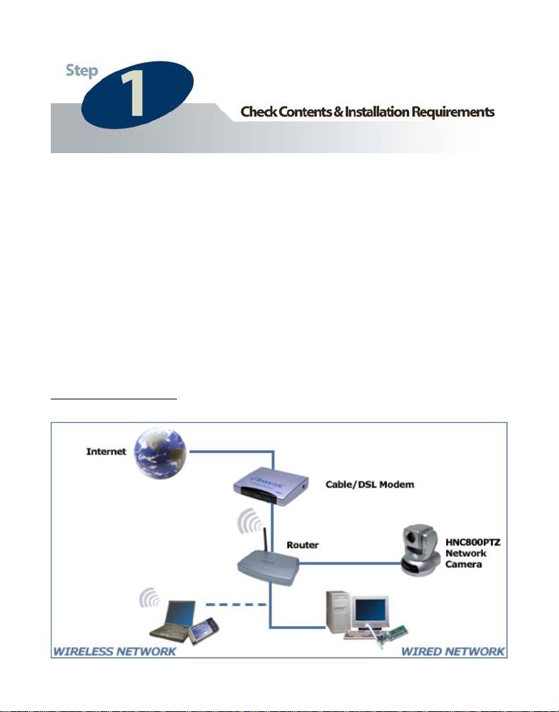
General Installation:
3
Page 4
4
Page 5
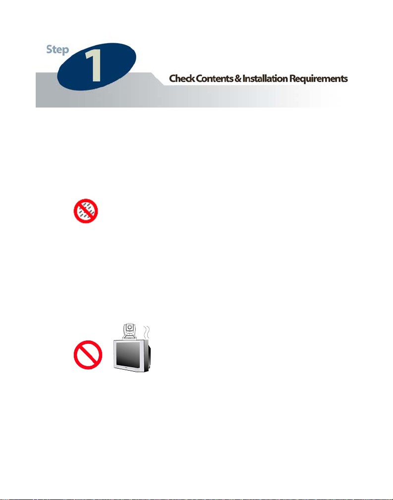
Please review the cautionary instructions below before installing the
HNC800PTZ:
• Keep the network camera away from water. If the network
camera is wet, power it off immediately. (If such an event
ase contact your dealer.) should occur, ple
• If the camera begins to smoke or release an unusual smell, power
it off immediately. (If such an event should occur, please
contact your dealer.)
• Do not place the camera around heat sources such as ovens,
televisions, etc.
• Refer to the user’s manual for the correct operating temperature
range to ensure the proper operating environment.
5
Page 6
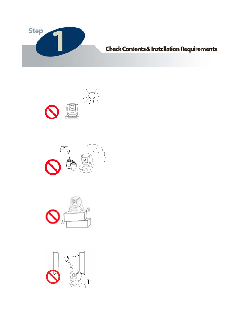
• Keep the network camera away from direct sunlight.
• Do not place the network camera in humid environments.
• Do not place the network camera on unsteady surfaces.
• During thunder/lightning storms, be cautious of electrical surges.
6
Page 7
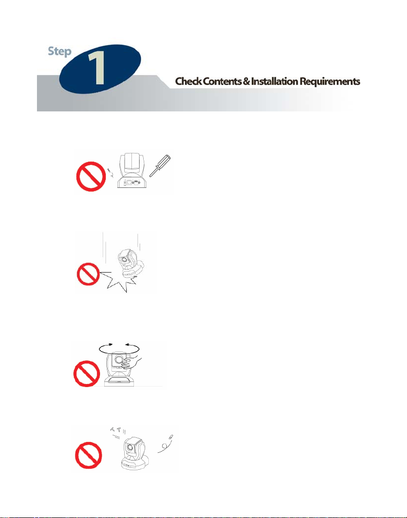
• Do not disassemble the network camera.
• Do not drop the network camera.
• Do not manually pan and tilt the network camera while the
power is turned on.
• Do not insert any foreign objects into the camera.
7
Page 8

Front Panel
Lens
Microphone
Status LEDs
Rear Panel
Bottom Panel
Pwr. Input
External mic.
LAN port
External I/O
A/V Out
Note: For reference, please
locate the MAC Address
(same as Series Number)
on the bottom panel of the
unit.
8
Page 9

1 If you choose to connect any external
devices such as sensors, alarms, etc., you
can connect them to the I/O terminal block.
(Please refer to the user’s manual for I/O
voltages.)
1
2 Locate the network cable connector
(RJ-45 port) on the left-hand side of the
rear panel of the camera. Connect an
Ethernet cable to the port. Connect the
other end of the cable to the network.
2
3 Locate the power input connector on
the left-hand side of the rear panel of the
camera and attach the external power
supply. To ensure the camera is powered
on, please check to see that the red
“Power/MIC” LED located on the black
plastic panel on the front of the camera is lit.
(To ensure a network connection, please
check to see that the green “Activity” LED
is lit or flashing.)
3
9
Page 10

Insert the Hawking Net-Vision
1
into your CD-ROM Drive. When the main page loads, click on IP Setup &
Utility.
TM
HNC800PTZ Installation & Utilities CD
1
10
Page 11

When the “IP Setup Wizard and Management & Control Software” page
2
loads, click on IP Setup. This will install the IP Setup wizard onto your PC.
2
11
Page 12

Once the IP Setup wizard has been installed onto your PC,
3
an IP Setup icon will appear on your PC’s Desktop. Click on
this icon to run the IP Setup wizard.
4
The I
si r cameras on your local area
n rk. A “similar” camera will have
the same code of four letters at the
beginning of its serial number. (The
serial number is different from the
series number/MAC address.) This
code is “HVVT” and can be found on
either the right or left panel of the box,
or on the label on the bottom of the
camera.
P Setup program will search for
mila
twoe
12
Page 13

5 After completing the search, the main IP Setup window will ap
as you have a DHCP server on your network (most networks
program should have returned an IP address for your network
“IP Address” heading, that is consistent with your existing LAN settin
pear. As long
do), the IP Setup
camera, under the
gs.
Note: A DHCP server provides IP addresses to client devices on the same
(
etwork.)
n
Check the box next to the “Series Num
esired camera.
d
ber” (same as MAC Address) of the
(Note: If the IP Setup window does no
Search” button at the bottom of the win
“
ameras on your network. If clicking the “
c
ameras in the white camera list area, you
c
o insert into the reset hole on the left side
t
he base of the camera. Hold the “Reset
t
EDs will flash continuously and stop twic
L
fter the
a
second stop, release the button.)
t
display any devices, click on the
dow. This will search for all similar
Search” button does not return any
will need to find a tool small enough
[if facing the front of the camera] of
” button for two full cycles. The two
e. When the red LED begins to flash
the IP Address returned by the IP Setup wizard is not consistent with your
If
AN settings, there is no DHCP server on your network, or you want to
L
assign/change the IP address manually, you can refer to either: a. the IP Setup
wizard’s manual, or b. the HNC800PTZ user’s manual.
(Note: If you do not know how to determine the IP Addressing scheme for your
network, a detailed example is provided in the “Appendix” section of this QIG.)
13
Page 14

5
14
Page 15

Click on “Link to selected device” to connect the camera, whose “Series
6
Number” (MAC Address) you checked in the IP Setup window, to Internet
Explorer. This will open the camera’s webpage, from which you can further
configure and control the device.
6
6
15
15
Page 16

Note
It is highly recommended that you now go to the network camera’s webpage and
ensure that the device has been configured with the appropriate network settings.
Once the IP Setup program returns a valid IP address, please go to the network
amera’s homepage by either clicking on “Link to Selected Device” in the IP
c
etup window, or typing the camera’s IP address in your web browser’s
S
Address” bar. In the camera’s homepage, click on “Configuration”. Then, click
“
n “Network” in the column menu on the left side of the page. Please ensure that
o
our camera’s network settings are consistent with your existing LAN settings. If
y
ey are not, you can set them in the fields provided (see figure below). Once you
th
re sure that the camera’s network settings are correct, click on “Use fixed IP
a
ddress”. The camera’s IP address will then always remain the same, and you can
a
ip having to perform the installation procedure each time the camera reboots.
sk
lease be sure to click Save at the bottom of the page to confirm the new settings.
P
16
Page 17

• The HNC800PTZ has a default IP Address of: 192.168.0.99. The
Administrator’s default user name is “root” and it cannot be changed . The
Administrator’s defaul t pa sswor d is bla nk.
• The IP Setup wizard has many additional functions that have not been
described in this QIG. For detailed explanations of these functions, it is
highly recommended that you review the IP Setup wizard’s manual,
located on the CD that was included with the HNC800PTZ’s packaging.
To access the manual, click on “IP Setup & Utility” when the main page
of the CD loads. Then, in the “IP Setup and Management & Control
Software” page that follows, click on “IP Setup Manual”.
• You can access and view your network camera’s images via a web browse r
using two methods:
1. In your web browser’s address bar, type in
“http://IPAddressofCamera”.
2. In the IP Setup window, click on Link to selected
• You can also use the included software a
playback the network camera’s im ages.
• The example illustrated in the previous section “Step 4: R
Program” de work camera
within your LAN. For an example of how to view your network camera
outside of your existing LAN via the In the section in
the user’s manual titled “How to View the Internet”.
• If the image is blurry, this is most likely because the camera is out of foc us .
To focus the camera, click on either the p on the “Focus”
button on the camera’s homepage.
• It is highly recommended that you install the network cameras
before placing them in the desired physical location.
device.
pplication to view, record, and
un the IP Setup
als with setting up an IP address to view the net
ternet, please refer to
Your Camera via
lus or minus sign
17
Page 18

Ho o
w t Determine the IP Addressing Scheme for your Network
The exa termine the IP Addressing
sche e
procedu
mple shown here illustrates how to de
m for your network, using the Windows XP operating system. The
re is similar for all other versions of Windows.
When s
specify
on your
foll in
segm n
devices
“10.1.1”. Therefore l d
the form “10.1.1.x” e
setting the IP addres r
equ d
r ire ) that you choose a number towards the end of the range between
0 an 2
as the final seg
Sele n
and 250
being u
etting an IP address, you must make sure that the address you
has the same first three octets (or segments) as the other devices
LAN. In the figure on the previous page, the camera has the
ow g IP address: 10.1.1.114. The address is comprised of four
e ts separated by periods. Each segment is called an “octet”. All
on your LA uN m st have the same first three octets, in this case
, al evices on your LAN must have IP addresses of
, wh re “x” is a number between 0 and 254. When
s fo the network camera, it is recommended (but not
d 54, excluding 254 itself. (Occasionally, the number 254 is used
ment for the default IP address of other devices.)
cti g a number towards the end of the range (preferably between 200
) will help avoid conflicts with IP addresses that are already
sed by other devices on the LAN.
To e
det rmine the common octets/segments for your LAN settings, follow
the st p
e s outlined in the next two pages.
18
Page 19

a. Click on Start in
the bottom left corner
of your screen. Then
click on My
Network Places.
a
19
Page 20

b. Click on View
Network Connections .
b
20
Page 21

c. In the Network
Connections
window, you should
see an icon titled
Local
c
Area Connection (or
something similar).
You can access this
icon in two ways:
a. by clicking or
double-clicking on it,
or b. by right-clicking
on it and then
clicking on Status
from the resulting
21
Page 22

d. A window with the
title Local Area
Connection Status
(or something similar)
will
appear. Click on the
Support tab. Under
the heading Address
Type, you will find
an IP Address line
and a Default
Gateway line. These
two lines will have IP
addresses with the
first three octets in
common. Use this
inform
IP address for y
network camera. You
will use these same
three octets as the
first three octets for
the IP address of your
network camera. The
final octet will be a
number between 0
and 254.
d
ation to set the
our
22
 Loading...