

Page 1
Page 2
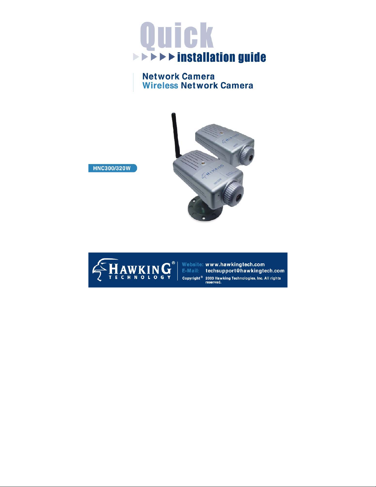
Congratulations on the purchase of your new HNC300 Wired or HNC320W
Wireless Network Camera. The HNC300 and HNC320W are high
performance standalone camera systems that provide an ideal solution for
remote monitoring, surveillance, or sending live video over the Internet.
The cameras offer a broad array of applications and can be used to monitor
various critical locations such as homes, offices, banks, schools, childcare
centers, hospitals, and other industrial and public areas. Please read this
quick installation guide carefully before beginning your installation.
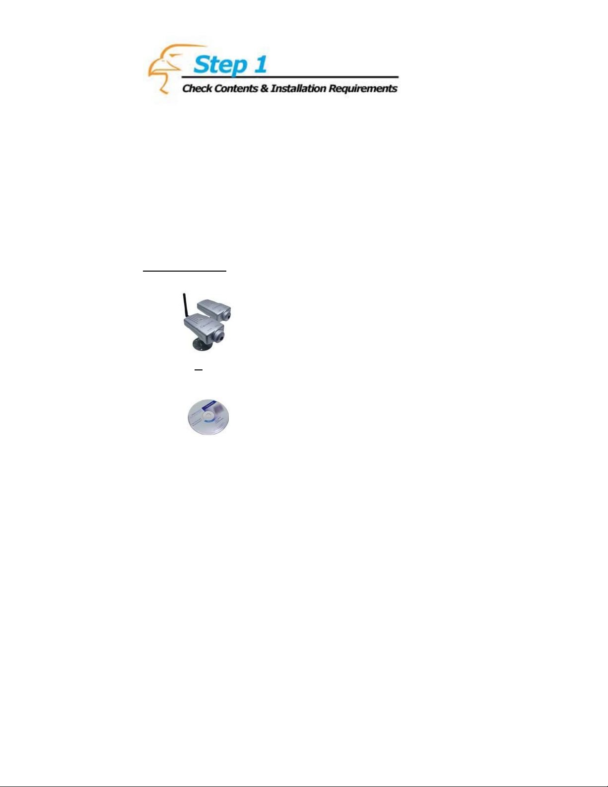
Before starting, please check the contents of your package:
Package Contents
1)
HNC300 or HNC320W
Network Camera
2)
One Setup CD-ROM
Page 3
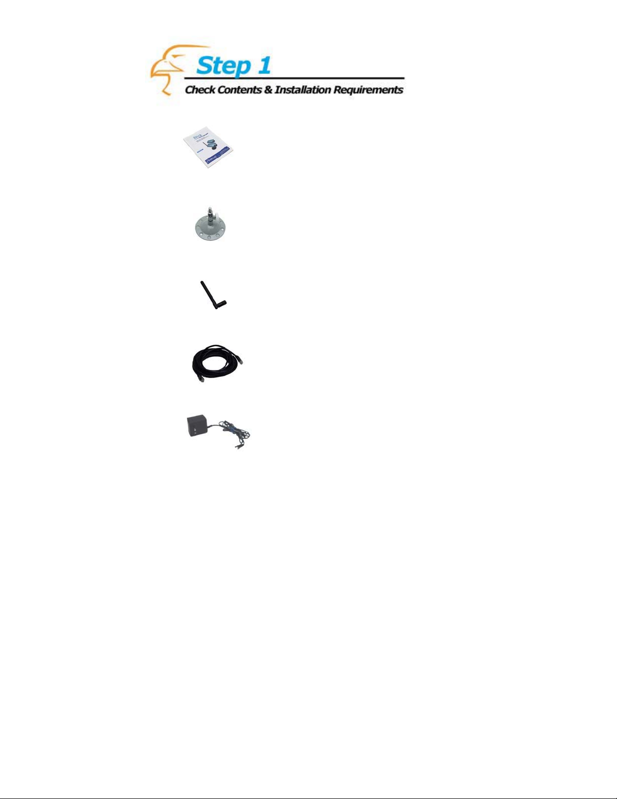
3)
One Quick Installation Guide
4)
One Camera Stand Kit
5)
One Wireless Antenna (HNC320W only)
6)
One Category 5 Ethernet Cable
7)
One Power Adapter
Page 4

What You Will Need to Get Started
x Wired Router/Switch/Hub (or Wireless 802.11b/g Router or
Access Point [for the HNC320W only])
x CD-ROM Drive
x Web Browser
System Requirements
x CPU: Pentium II, 266 MHz or above
x Memory Size: 32 MB (64 MB recommended)
x VGA Card Resolution: 800 x 600 or above
x Internet Explorer 5.0 or above (ActiveX & Java Mode – View
Images with Windows OS; Java Mode – View Images with
Other Operating Systems)
x Netscape 6.0 or above (Java Mode – View Images)
Page 5
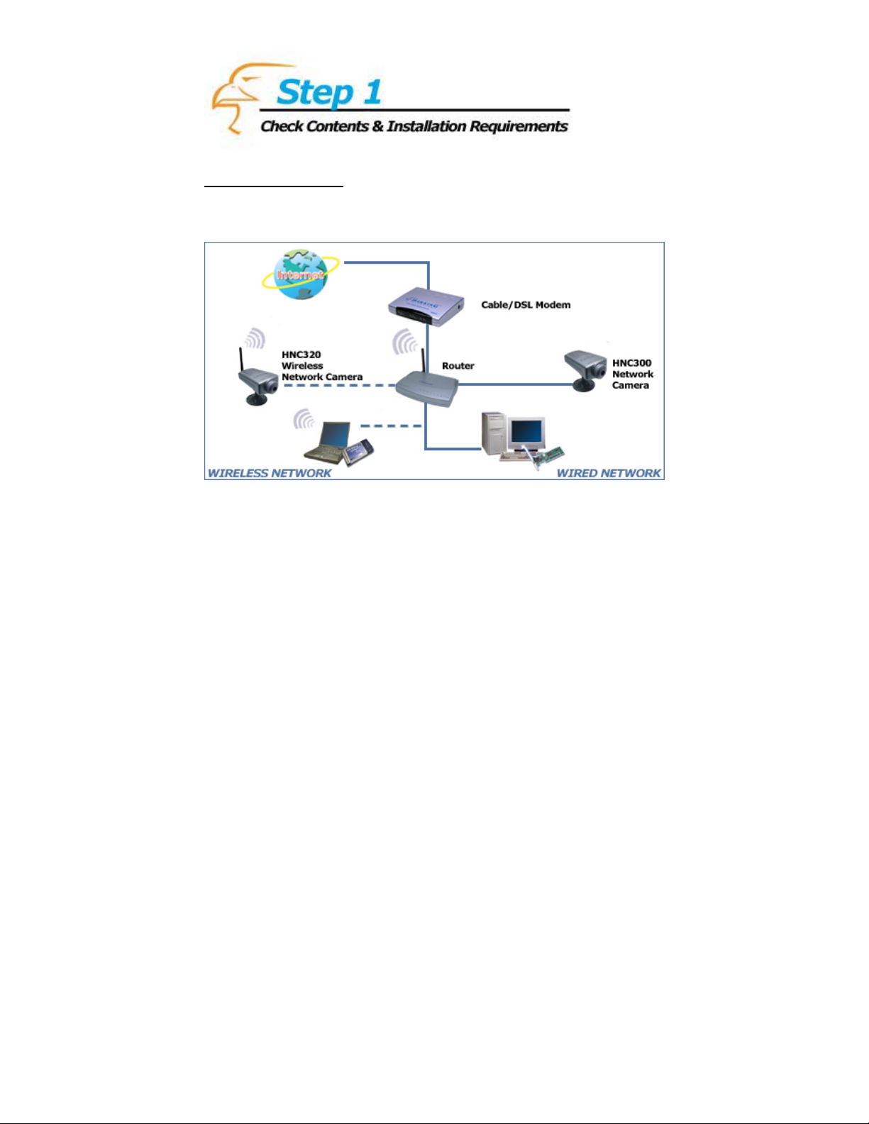
Installation Diagram
Page 6

n
f
p
t
d
d
p
r
n
N
r
d
t
1 (For the HNC320W only) Locate
r
the antenna connector near the cente
of the rear panel of the camera. Screw
the base of the antenna (included with
the HNC320W) into the antenna
connector.
2 Locate the network cable connecto
(RJ-45 port) on the left-hand side of the
rear panel of the camera. Connect a
Ethernet cable to the port. Connect the
other end of the cable to the network.
ote (HNC320W only): For prope
installation, it is highly recommende
that you use the Ethernet port to
configure the camera, and then install i
in the desired location.
3 Locate the power input connector o
the right-hand side of the rear panel o
the camera, and attach the external
ower supply. Please check to see tha
the blue “Pwr” (Power) LED locate
next to the lens of the camera (front side)
is lit to ensure that the camera is powere
on. (To ensure a network connection,
lease check to see that the orange “Lnk”
[Link] LED is lit.)
1
2
3
Page 7
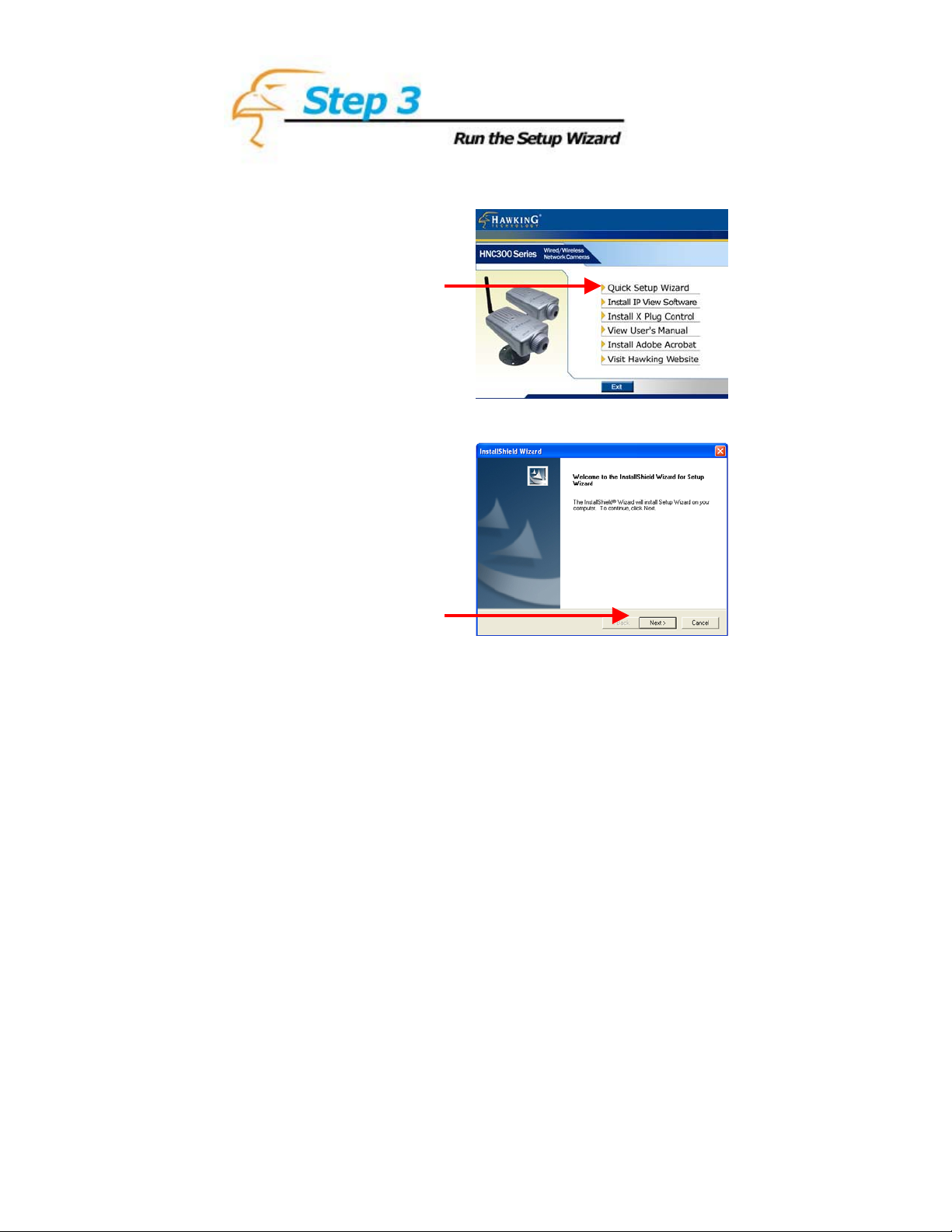
1 Insert the Hawking
r
HNC300 Series Installation
& Utilities CD into you
CD-ROM Drive. When the
main page loads, click on
Quick Setup Wizard.
2 Click Next.
1
2
Page 8
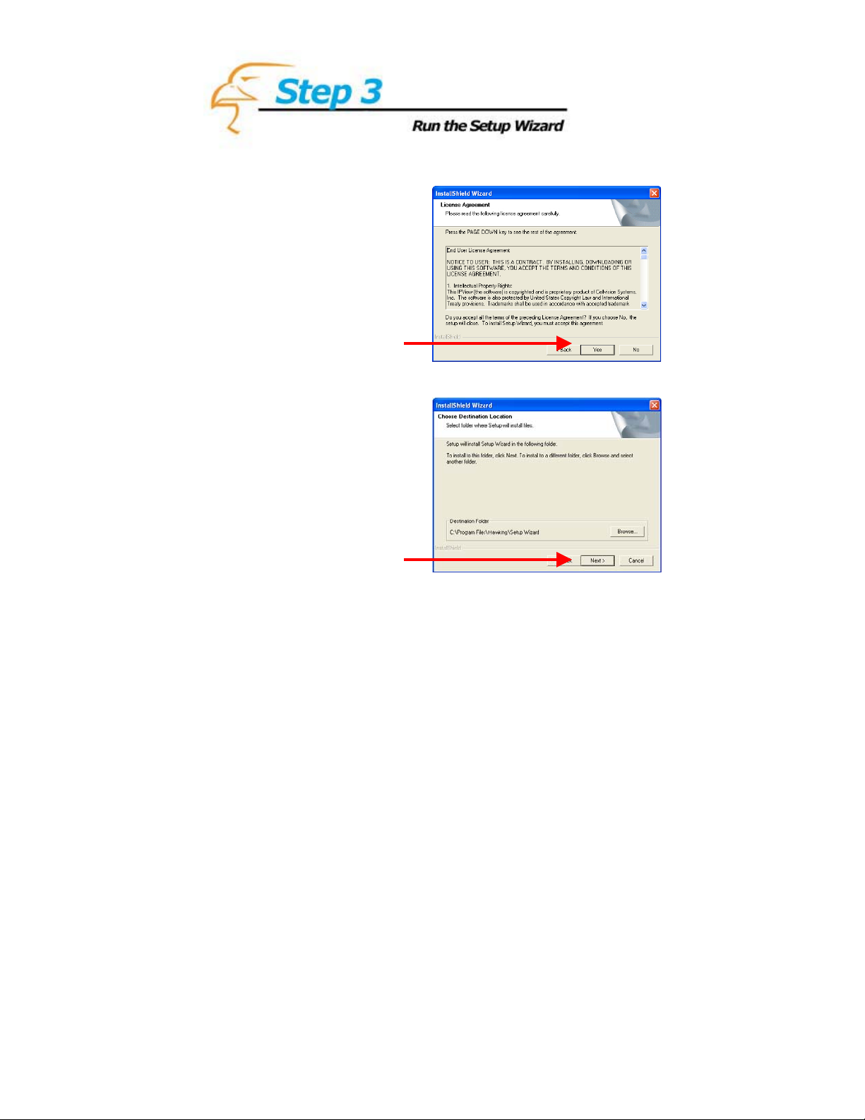
3 Click Yes.
4 Click Next.
3
4
Page 9

.5 Click Finish
5
Page 10

HNC300
e
lick on Start, and locate the Setup Wizard in the Programs menu.C
1 When you launch th
Setup Wizard, the main
window will appear, as
shown. The connected
camera(s) will be displayed.
Select the camera you want
(according to MAC
Address) and click Wizard
to begin.
2 If the default IP address
(192.168.0.20) does not
correspond with your
existing local area network
settings, this screen will
appear. You will need to
assign an IP address for the
camera that corresponds to
your network’s existing IP
addressing scheme.
1
2
Page 11

2.5 The default Admin ID
P
e
and Password a
When running t
Wizard for the first time,
please leave these two fields
blank. Otherwise, input the
appropriate Admin ID and
Password. Then click OK.
re blank.
he Setup
3 In this window, set the IP
address, subnet mask, and
gateway, such that they
correspond to your
network’s existing I
address scheme. (Th
default values are shown
here.) If you are unfamiliar
with how to set these values
to be consistent with your
network’s existing IP
address scheme, a detailed
example is provided in the
Appendix of this Quick
Installation Guide.
2.5
3
Page 12

S
sek
”
e
n
y
teps 2-3 in the previous pages will only occur for the initial setup or after
a Factory Default Reset has been performed. For all subsequent set
lease follow Steps 4-8 in the pages that follow.
p
4 To obtain an IP Addres
automatically, click on th
“Obtain…” radio button.
Then click Next. Otherwise, click on the “Static
radio button and input th
appropriate information i
the fields below. Then clic
Next. Note: the IP Addr
Subnet Mask, and Gatewa
must correspond
with your existing
network settings.
ess,
4
ups,
Page 13

5 To protect your camer
a
s
d
k
b
e
”
w
”
e
e
n
t
c
P
t
from unauthorized acces
and use, you will need to
change the Admin ID an
Password, which are blan
y default. To chang
them, check both “Change
boxes, and input a ne
Admin ID and Password
Then, click Finish.
6 If you selected “Static
in “4” and input th
information manually, th
status page shown i
Figure 6 will appear. I
will display your basi
authorization and I
information. Click Next to
continue. If you did no
select “Static” in “4”,
the Setup Wizard will
proceed directly to “7”.
.
5
6
Page 14

7 Click Reboot to save th
e
d
fera
n
s
p
s
new settings. If you woul
like to see an example o
how to view your cam
via the Internet, you ca
click on the link on thi
age to access the camera’
user’s manual.
8 The setup process has
now been completed. After
clicking Reboot, the main
window of the Setup
Wizard will appear again.
Clicking on Access the
selected camera will
automatically launch the
web browser and allow
you to view your
camera’s images.
7
8
Page 15

HNC320W
e
Click on Start, and locate the Setup Wizard in the Programs menu.
1 When you l
Setup Wizard, the main
window will appear, as
shown. The connected
camera(s) will be displayed.
Select the camera you want
(according to MAC
Address) and click Wizard
to begin.
aunch th
1
2 If the default IP address
(192.168.0.20) does not
correspond with your
existing local area network
settings, this screen will
appear. You will need to
assign an IP address for the
camera that corresponds to
your network’s existing IP
addressing scheme.
2
Page 16

2.5 The default Admin ID
p
s
e
d
y
r
e
r
s
r
P
A
P
n
k
and Password are blank.
When running the Setup
Wizard for the first time
lease leave these two field
blank. Otherwise, input th
appropriate Admin ID an
Password. Then click OK.
3 In this window, set the IP
address, subnet mask, and
gateway, such that the
correspond to you
network’s existing I
address scheme. (Th
default values are show
here.)If you are unfamilia
with how to set these value
to be consistent with you
network’s existing I
address scheme, a de
example is provided i
ppendix of this Q
Installation Guide.
tailed
n the
ic
u
,
2.5
3
Page 17

s
e
Steps 2-3 in the previous pages will only occur for the initial setup or after
”
k
e
n
y
a
Factory Default Reset h
p
lease follow Steps 4-9 in
as been performed. For all subsequent setups,
the pages that follow.
4 To obtain an IP Addres
automatically, click on th
“Obtain…” radio button.
Then click Nex
wise, click on the “Static
radio button and input t
appropriate information i
the fields below. Then clic
Next. Note: the IP Address,
Subnet Mask, and Gatewa
must correspond
with your existing
network settings.
t. Other-
h
4
Page 18

5 The Connection Mod
e
e
a
e
k
-
n
k
,
t
k
a
s
d
k
b
e
”
b
w
will depend on how th
camera is connected to th
network. If you are using
router or access point, clic
on Infrastructure. For peer
to-peer connection, click o
Adhoc. The Networ
Name, Wireless Channel
and Encryption Key mus
correspond with
your wireless networ
settings. Click Next.
5
6 To protect your cam
from unauthorized acces
and use, you will need
ge the Admin ID anchan
Password, which are blan
y default. To chang
them, check both “Change
oxes, and input a ne
Admin ID and Password.
Then, click Finish.
er
to
6
Page 19

7 If you selected “Static
”
e
e
n
t
c
P
t
e
d
f
a
n
s
p
s
in “4” and input th
information manually, th
status page shown i
Figure 7 will appear. I
will display your basi
authorization and I
information. Click Next to
continue. If you did no
select “Static” in “4”,
the Setup Wizard will
proceed directly to “8”.
8 Click Reboot to save th
new settings. If you woul
like to see an example o
how to view your camer
via the Internet, you ca
click on the link on thi
age to access the camera’
user’s manual.
7
8
Page 20

9 The setup process ha
s
r
n
e
l
e
now been completed. Afte
clicking Reboot, the mai
window of the Set
Wizard will appear agupain.
Clicking on Access th
selected camera wil
automatically launch th
web browser and allow
you to view your
camera’s images.
9
Page 21

x You can access and view your network cam
browser using two
methods:
In your web browser’s address bar, type in
1.
“http://IPAddressofCamera”.
On the main page, of the Setup Wizard, click on
2.
Access the selected camera.
era’s images via a web
x You can also use th
playback the netwo
x
The example
setting Iup an
an example o
LAN via the Internet, please refer to the section in th
“How to View Your Camera via the Internet”.
x If the image is blur
of focus. To focu
until the desired l
aggressively turn
unscrewing or dam
x It is highly recomm
placing them in the
x The ActiveX control might be disabled. If you are viewing the images
from Internet Explorer make sure ActiveX has been enabled in the
Internet Options menu. Alternatively, you can use the Java Applet for
viewing the required images.
e included software application to view, record, and
rk camera’s images.
illu in the Appendix section that follows deals with
strated
P ad ss to view the network camera within your LAN. For
dre
f how to view your network camera outside of your existing
e user’s manual titled
ry, this is most likely because the camera lens is out
s the lens, gently rotate the lens in either direction
evel of focus is reached. Please Note: Do not
or overturn the lens, as this could lead to an
aging of the lens.
ended that you install the network camera(s) before
desired physical location.
Page 22

Example on How to Set t
he IP Address Manually
T
he example shown here
u
sing the Windows XP o
s
imilar for all other versio
W
hen setting an IP addr
s
pecify has the same first
o
nyourLAN. Inth
fo
llowing IP address
s
egments separated by
d
evices on your LAN must have the same first three octets, in this case
“1
0.1.1”. Therefore, all devices on your LAN must have IP addresses of
th
e form “10.1.1.x”, where “x” is a number between 0 and 254. When
s
etting the IP address for the network camera, it is recommended (but not
required) that you choose
0
and 254, excluding 254
as the final segment for the default IP address of other devices.)
S
electing a number towar
a
nd 250) will help avoid
b
eing used by other devic
T
o determine the common octets/segments for your LAN settings, follow
th
e steps outlined in the next two pages.
illustrates how to manually set an IP address
perating system. However, the procedure is
ns of Windows.
ess, you must make sure that the address you
three octets (or segments) as the other devices
e figure on the previous page, the camera has the
: 10.1.1.25. The address is comprised of four
periods. Each segment is called an “octet”. All
a number towards the end of the range between
itself. (Occasionally, the number 254 is used
ds the end of the range (preferably between 200
conflicts with IP addresses that are already
es on the LAN.
Page 23

a. Click on Start i
n
r
n
y
the bottom left corne
of your screen. The
click on M
Network Places.
a
Page 24

b. Click on Vie
w
Network Connections.
b
Page 25

r
r
n
c. In the Networ
k
d
d
Connections
window, you shoul
see an icon title
Local
c
Area Connection (o
something similar).
You can access this
icon in two ways:
a. by clicking o
double-clicking on it,
or b. by right-clicking
on it and the
clicking on Status
from the resulting
Page 26

r
d
t
n
d
d. A window with the
title Local Area
Connection Status
(or something similar
will
d
appear. Click on the
Support tab. Unde
the heading Address
Type, you will fin
an IP Address e
and a Defaul
Gateway line. These
two lines will have IP
addresses with the
first three octets i
common. Use this
information to set the
IP address an
Gateway for your
network camera. Use
these common three
octets as the first three
octets for the IP
address of your
camera. The fourth
octet will be a number
between 0 and 254.
lin
)
 Loading...