

Page 1
1
Page 2

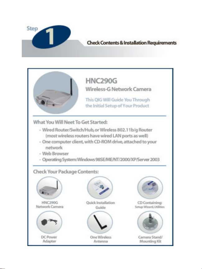
Step 1: Check Contents & Installation Requirements 3
Step 2: Physical Description 5
Step 3: Hardware Installation 7
Step 4: Run the Quick Setup Wizard 9
Step 5: Accessing the Network Camera 28
Step 6: Viewing & Tips 30
Appendix 31
2
Page 3
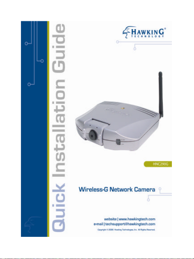
Congratulations on the purchase of your new Hawking Net-
TM
Vision
HNC290G Wireless-G Network Camera. The
HNC290G is a high performance stand -alone camera system that
provides an ideal solution for remote monitoring, surveillance, or
sending live video over the Internet. The camera offers a broad
array of applications and can be used to monitor various critical
locations such as homes, offices, and other industrial and public
areas. Please read this quick installation guide (QIG) carefully
before beginning your installation.
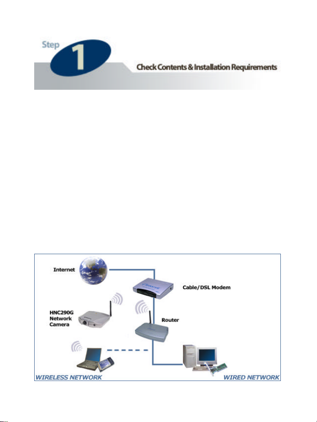
General Installation:
3
Page 4
4
Page 5
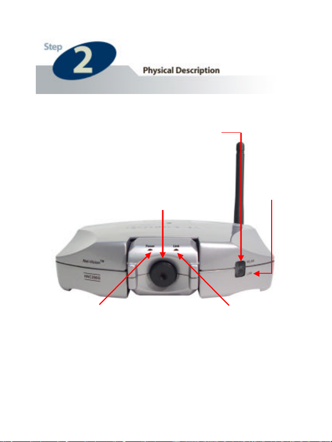
LED:
LAN
LED: Power
LED:
LED: Link
LED:
Front Panel
LEDs
- Power: Green when device is powered on & ready for access
- Link: Orange when monitoring
- WLAN: lit for wireless link; flashing for video
transmission/reception
- LAN: lit for wired link; flashing for video transmission/reception
WLAN
LAN
5
Page 6
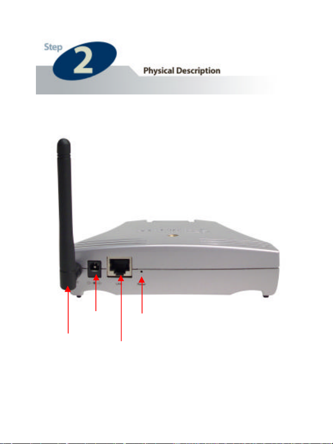
Power
Input
Reset
Button
LAN
Back Panel
Antenna
Port
6
Page 7
2
1
1
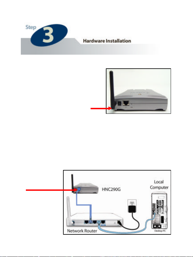
Locate the antenna
connector on the left side
of the camera’s rear panel.
Screw the base of the
antenna (included with the
HNC290G) into the
antenna connector.
2 Locate the network cable connector (RJ-45 port) on the
camera’s rear panel. Connect an Ethernet cable to the port.
Connect the other end of the cable to the network (i.e. a
router or switch). NOTE: For initial setup, you will need
to use a wired connection. After completing the setup and
configuration, you can begin using your camera wirelessly.
7
Page 8
3
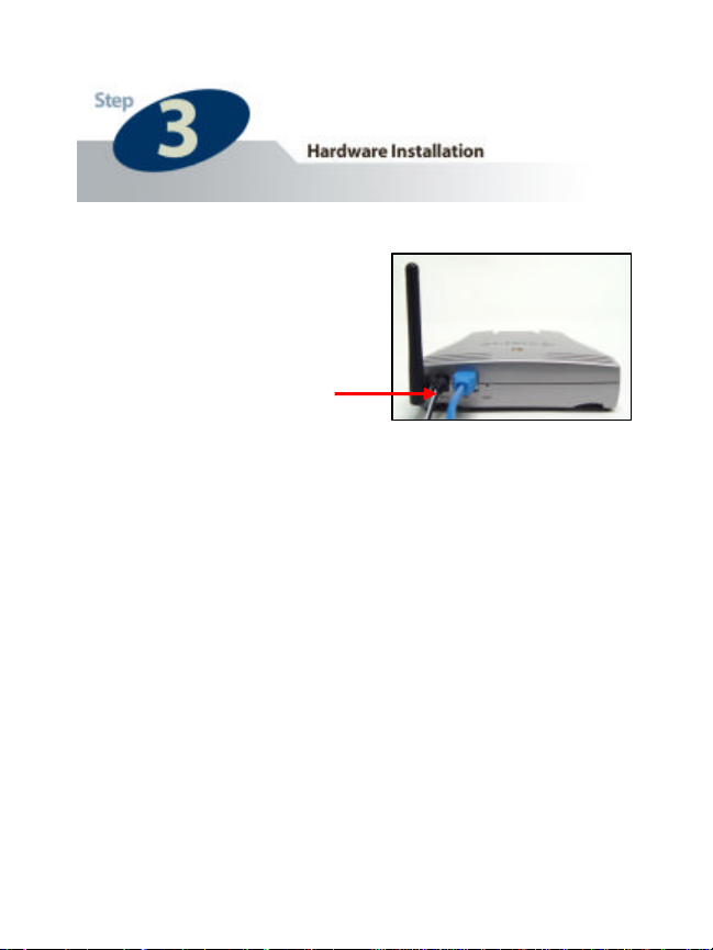
3 Locate the power input
connector on the camera’s
rear panel, and attach the
external power supply.
Then, plug the adapter
into an available outlet.
Please check to see that
the green “Power” LED
located above the lens of
the camera is lit to ensure
that the camera is
powered on. (To confirm
that there is a network
connection, please check
to see that the orange
“Link” LED is lit or
flashing.)
8
Page 9
1
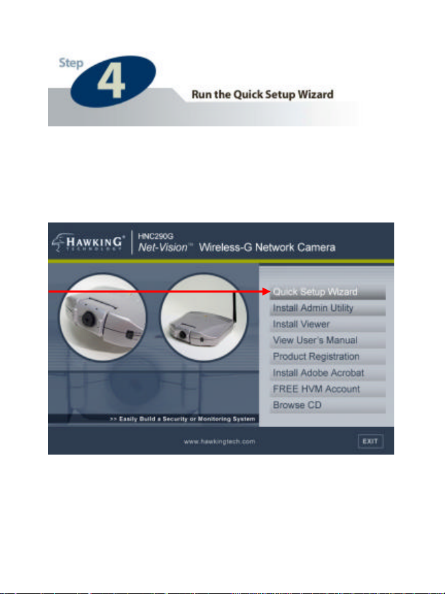
1 Insert the Hawking Net-Vision
TM
HNC290G Installation &
Utilities CD into your CD -ROM Drive. When the main page
loads, click on Quick Setup Wizard.
9
Page 10
2
2 The Setup Wizard will search for similar cameras that are
available on your local area network. A “similar” camera will
have the same code of four letters at the beginning of its serial
number. This code is “HEMT” and can be found on either the
right or left panel of the box, or on the label on the bottom of
the camera.
10
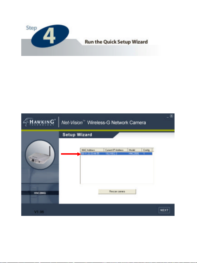
Page 11

Each available camera will be displayed in the camera list
with its MAC address, current default or configured IP
address, and model number. (NOTE: The Setup Wizard may
display an IP address for the new camera that is already
consistent with your local area network [LAN] settings, rather
than the default one.) In the camera list, click on the camera
you would like to configure so that it is highlighted blue, and
then click Next. (If you are unsure about which camera you
would like to configure, you can compare a camera’s MAC
address in the camera list with the one printed on the label on
the underside of the camera.)
NOTE: If the camera list does not display any available
cameras, you should:
a. Click on the “Rescan Camera” button, and
b. Make sure that all available similar network cameras are
connected properly to the network.
If neither option above is successful, you can also perform a
factory default reset on the camera by holding down the
“Reset” button on its back panel for at least five seconds.
Then, allow about 45 seconds to one minute for the camera to
complete the reboot process. This should resolve the issue.
11
Page 12

3
3 Next, the login username and password screen will appear.
Please type in the default login and password and then click
“OK”. The default values are:
Login: admin
Password: 1234
(If you have previously set a username and password, enter
them and press “OK ”.)
12
Page 13

4 The Setup Wizard will try to determine your network settings.
Click on DHCP. If a DHCP server is present on yo ur network,
the Wizard will obtain your network settings and automatically
configure your network camera by returning an IP address that is
consistent with your network. (If the Setup Wizard does not
automatically return an IP address in the “DHCP” category, try
clicking on Manual IP and the DHCP again.)
If no DHCP server is present, the Wizard will poll your PC’s
internal network settings and suggest an appropriate static IP
address in the “Manual IP” section to assign to the network
camera. If you do n ot wish to use the suggested IP address, you
may change your IP settings in the “Manual IP” section only.
NOTE: Typically, your Gateway address is the IP address of your
network’s router or Internet gateway. The Wizard will try to
automatically fill this field, based on your PC’s current settings.
Please click Next once your computer has found the appropriate
IP settings.
NOTE: If you are unfamiliar with how to manually set an IP
address, an example is provided in the Appendix (see pg. 30).
13
Page 14

4
14
Page 15

5
5 The Wireless Network setup screen will allow you to
connect your wireless network camera to your wireless router,
or access point. (Infrastructure Mode is most commonly used
in this setup.)
15
Page 16

Please highlight the appropriate wireless network that you
would like to assign the network camera to. You may choose
to scan for the following two types of networks: Infrastructure
(if you are using a router or access point) or Ad-hoc (for peerto-peer connection). Or, you may enter in your wireless
network information manually.
Click Next once you have selected your wireless network.
6 If you chose to connect to an encrypted network (one that
has “WEP” or “WPA” listed under the “Security” category on
the “Wireless Network” screen), the Security screen on the
following page will appear. If you are connecting to a non-
encrypted wireless network, please click Next.
The “Security” screen allows you to set wireless encryption for
your network camera. Please note that your router or access
point must be broadcasting its wireless signal using the same
encryption method that you apply on this screen. There are
three available encryption methods: a. WPA, b. WEP 64-Bit, c.
WEP 128 -Bit. When using any of these encryption methods,
you must assign the same encryption key as the one used to set
up your router or access point.
Click Next once you have set up your encryption method.
16
Page 17

6
17
Page 18

7
7 To protect your camera from unauthorized access and use,
you will need to change the Admin Password, which is
“1234” by default. The password can have a maximum of
four characters. Confirm the new password by typing it
identically in the “Reconfirm” field. (Please note that the
Admin ID is simply “admin”.)
Click Next once you have confirmed your new password.
18
Page 19

8
8 The following status screen will appear. It will display a
summary of the changes you have made to the network
camera’s settings. If all the settings are correct, click Next to
continue.
19
Page 20

9
9 The following screen will prompt you to set up your camera
for Internet viewing. The setup is easy and will only require
minimum input from you. Once configured, you will be able
to view your camera from anywhere in the world, using only a
web browser. If you would like to proceed with this setup,
click Next to continue. If you do not wish to view your
camera over the web, or if you wish to configure the camera at
a different time, click Skip.
20
Page 21

10
10 In the screen below, you can assign a web address for your
camera that will allow you to access it rem otely over the Internet.
In the field directly to the right of the text “Please Choose a
Domain Name”, enter a web address that will be easy for you to
remember, such as “myhome”. Then, in the scroll-down menu to
the right of this field, select a domain. Next, enter your email
address so that if you would like to, you can renew this service at
the end of the 75-day trial period. Finally, click Next. (You can
also skip this step by clicking Skip, but it is not recommended.)
21
Page 22

11 In order to view your camera remotely via the web, you will
need to open two virtual ports on your router: 1. a web port, and
2. a video port. (Since the HNC290G does not have an audio
feature, you will not need to open an audio port.) The Setup
Wizard screen on the next page will allow you to do this. By
opening these ports, you are essentially creating a “tunnel” from
inside your network to the outside, through which you can view
your camera via the Internet.
Novice Setup: If you are unfamiliar with how to open ports on
your router, or if you would simply prefer to have the Setup
Wizard configure your router with the default settings, click on
the radio button for Novice Setup . (The default settings are: web
port 80, video port 5000.)
Advanced Setup: If you are a more advanced user, or if you
know that port 80 is already in use on your network or has been
blocked by your ISP, click on Advanced Setup and enter a
different web port number. In most cases, video port 5000 will
not be in use, but you can change that as well if you prefer.
Manual Setup: If you are an expert/advanced user and would
like to configure the ports directly from your router, click on
Manual Setup . This will require you to log in to your router, and
access its configuration pages to change the port settings.
22
Page 23

11
NOTE: If your router does not support UPnP or if UPnP is not
enabled on your router, the Setup Wizard will not be able to
automatically open ports. You will need to select Manual
Setup to continue.
23
Page 24

12a
12a If you selected Manual Setup in the previous Setup Wizard
screen, the following screen will appear. Review all of the
information provided on the screen, and then click on the link for
step-by-step instructions on how to configure your router for portopening. It is highly recommended that you use the default ports:
web port 80 and video port 5000. If you choose not to use the
default ports, you will need to ensure that you make the
corresponding port changes to the camera (either from its web
user interface or Admin software utility) after you have made
them on the router.
24
Page 25

12b
12b If you selected Novice Setup or Advanced Setup and the
Setup Wizard failed to communicate with your router, the
following screen will appear. This typically occurs when UPnP
is not enabled on your router. Review all of the information
provided on the screen, and then click on the link for step- by-step
instructions on how to configure your router for port-opening. It
is highly recommended that you use the default ports: web port
80 and video port 5000. If you choose not to use the default
ports, you will need to ensure that you make the corresponding
port changes to the camera (either from its web user interface or
Admin software utility) after you have made them on the router.
25
Page 26

12c When you click on either of the links shown in 12a (pg. 24)
or 12b (pg. 25), you will be directed to the webpage shown
below. Follow the instructions provided on the page for a stepby- step guide on how to open ports on your router.
26
Page 27

13
13 The following stat us screen will appear. Review the settings
and ensure that they are correct. If any of the settings are
incorrect, please go back and correct them. If all of the settings
are correct, write down the displayed information so that you can
access your came ra: a. from within your LAN, b. remotely over
the Internet. (The next section, “Accessing Your Camera”, will
show you how to do this.) Then, click Finish. When you click
Finish, you will have completed the installation and setup for
your camera. The camera will automatically reboot itself. This
can take up to one minute.
27
Page 28

If you have configured all the settings correctly and clicked
Finish on the Setup Wizard, you will use two different
methods to access your netwo rk camera: one for within your
local area network (LAN), and another for remote access from
outside your network.
To access/view your camera locally, from within your
network (i.e. not remotely over the Internet) :
a. If you used the default web port 80 (see pg. 22), you can
access your camera by typing
“http://IPAddressofCamera” in the address bar of your
web browser, where “IPAddressofCamera” refers to the
IP address you established for the camera in the Setup
Wizard (see pg. 14).
b. If you used a port number other than 80 for the web port,
you will need to follow the IP address with a colon and
the new port number. For example, if you set the web
port number at 82, you would type the following into the
web address bar:
“http://IPAddressofCamera:82”
28
Page 29

To access/view your camera remotely over the Internet
(i.e. from outside your network):
a. If you assigned a web address to your camera in the Setup
Wizard (see pg. 21), you can access your camera simply
by typing that web address into the web address bar of
your web browser. For example, if you assigned the
name “myhome” and domain name “.hawkingcam.com”
to your camera, you would type the following into the
web address bar:
“http://www.myhome.hawkingcam.com”
b. If you did not assign a web address to your camera, but
you did open ports on your router (see pg. 23), you would
follow steps similar to those described on the previous
page. However, rather than using the IP address of the
camera, you would use the public/WAN/Internet IP
address of your router (followed by a colon and the web
port number if you chose not to use the default web port).
You can locate your router’s WAN IP address on the
status page of the router’s web user interface.
NOTE: If you did not open ports on your router and/or assign
your camera a web address, you will not be able access your
camera remotely.
29
Page 30

• The default IP address of the camera is: 192.168.2.3
• You can also use the included Admin and Utility software to
view, record, and playback the network camera’s images , as
well as to change the camera’s configuration settings.
• For a more detailed example of how to view your network
camera outside of your existing LAN via the Internet,
without using the domain name service described on pg. 21
of this QIG, please refer to the section in the user’s manual
titled “How to View Your Camera via the Internet”.
• If the image is blurry, this is most likely because the camera
lens is out of focus. To focus the lens, gently rotate the lens
in either direction until the desired level of focus is reached.
NOTE: Do not aggressively turn or overturn the lens, as this
could lead to an unscrewing or damaging of the lens.
• It is highly recommended that you install and set up the
network camera before placing it in the desired physical
location.
•
30
Page 31

Example on How to Set the IP Address Manually
The example shown here illustrates how to manually set an IP
address using the Windows XP operating system. However, the
procedure is similar for all other versions of Windows.
When setting an IP address, you must make sure that the address
you specify has the same first three octets (or segments) as the
other devices on your LAN. In the figures on the previous pages,
the camera has the following IP address: 10.1.1.144. The address
is comprised of four segments separated by periods. Each
segment is called an “octet”. All devices on your LAN must have
the same first three octets, in this case “10.1.1”. Therefore, all
devices on your LAN must have IP addresses of the form
“10.1.1.x”, where “x” is a number between 0 and 254. When
setting the IP address for the network camera, it is recommended
(but not required) that you choose a number towards the end of
the range between 0 and 254, excluding 254 itself. (Occasionally,
the number 254 is used as the final segment for the defa ult IP
address of other devices.) Selecting a number towards the end of
the range (preferably between 200 and 250) will help avoid
conflicts with IP addresses that are already being used by other
devices on the LAN.
To determine the common octets/segments for your LAN
settings, follow the steps outlined in the next two pages.
31
Page 32

a. Click on Start in the bottom left corner of your screen.
Then click on My Network Places .
a
32
Page 33

b. Click on View Network Connections .
b
33
Page 34

c. In the Network Connections window, you should see an
icon titled Local Area Connection (or something similar).
You can access this icon in two ways: a. by clicking or double clicking on it, or b. by right -clicking on it and then clicking on
Status from the resulting menu.
c
34
Page 35

d. A window with the title Local Area Connection Status
(or something similar) will appear. Click on the Support tab.
Under the heading Address Type, you will find an IP
Address line and a Default Gateway line. These two lines
will have IP addresses with the first three octets in common.
Use this information to set the IP address for your network
camera. You will use these same three octets as the first
three octets for the IP address of your network camera.
The final octet will be a number between 0 and 254.
35
Page 36

d
36
 Loading...