

Page 1
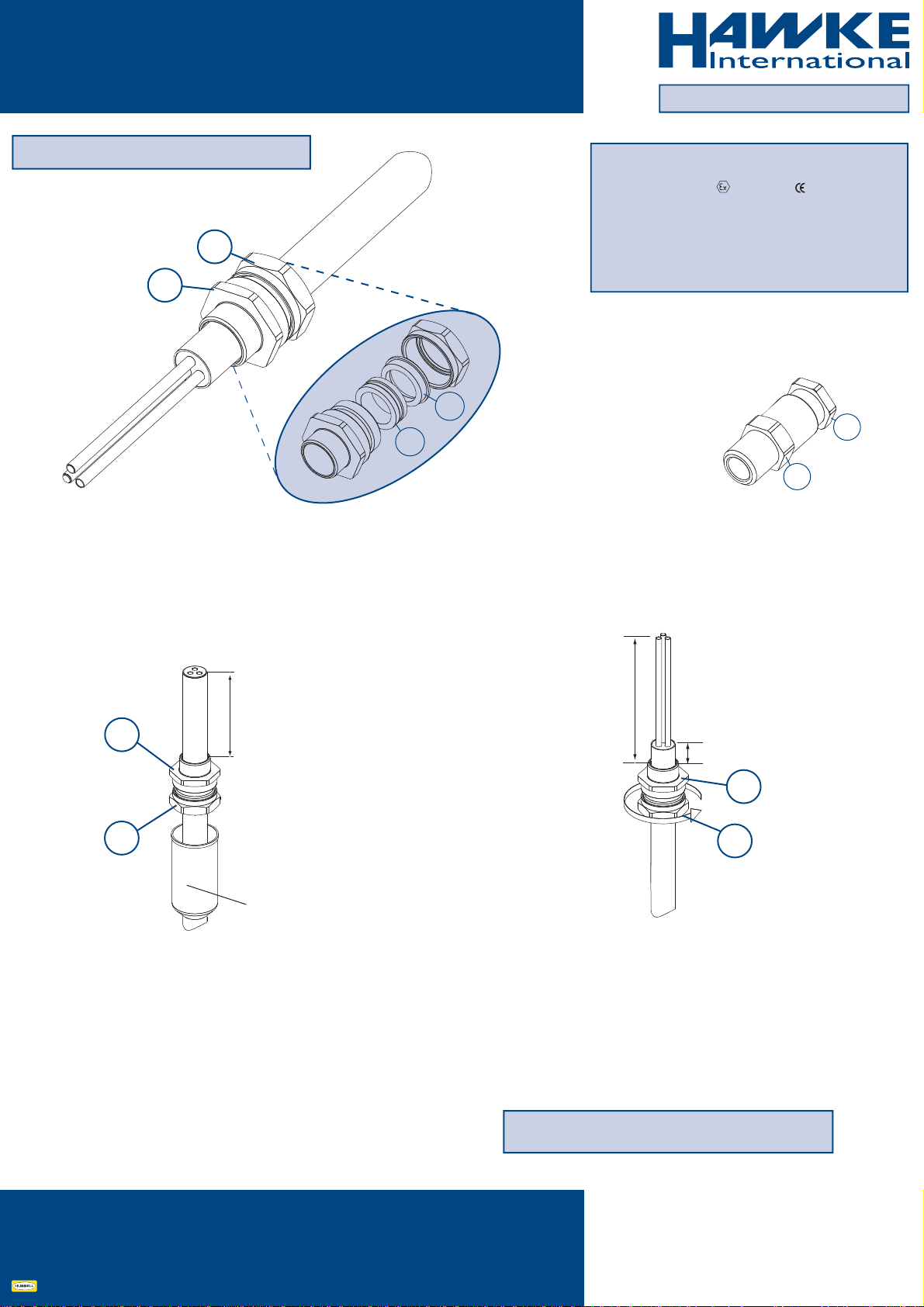
Assembly Instructions for cable gland:
501/421 Exd IIC Gb, Exe IIC Gb, Extb IIIC Db
AI 307 / Issue V - 09/16
Operating temperature range -60°C +100°C
1
2
1.2
1.1
Certication Details
Gland Type: 501/421 Exd IIC Gb, Exe II Gb, Extb IIIC Db
Baseefa06ATEX0056X II 2 GD IP66
IECEx BAS06.0013X
IEx 14.0272X
EAC ТC RU C-GB.ГБ05.B.00750
c CSA us No: 1015065
Class 1 Zone 1 AExd IIC, AExe II, Zone 21 AExtD
Class 1 Div 2 ABCD, Class II Div2 Groups EFG, Class III
1. Backnut
1.1 Compression Spigot
1.2 Seal
2. Entry
1
2
421/2K size only.
View for clarity only,
do not disassemble & .
Cable Preparation
II
2
1
Shroud Option
A
Allow sucient length of cable, II, to suit equipment.
If required, t shroud.
Pass cable through the cable gland as shown above.
Note : If the equipment has a threaded entry, it may be
advisable to screw the cable gland into the equipment to
prevent twisting of the cable after Step B
Gland Preparation
II
5mm minimum
recommended
2
1
B
Unless already screwed into the equipment, hold the entry in
position with a spanner/wrench to prevent rotation and tighten
the backnut using a wrench/spanner until resistance is felt
between the seal and cable. Then turn the back nut through a
further half to one full turn to complete the inner seal. Locate the
shroud over the cable gland, if applicable.
To ease wiring inside the equipment it may be benecial to strip
the outer sheath of the cable as shown above.
Connection Solutions
Hawke International is a division of Hubbell Ltd.
Registered No. 669157 in England. Registered Oce:
Cannon Place, 78 Cannon Street, London EC4N 6AF.
IMPORTANT: Support the cable to prevent it from twisting
www.ehawke.com
UK Oce
Oxford Street West,
Ashton-Under-Lyne,
Lancashire. OL7 0NA. UK
Sales: +44 (0) 161 830 6698
Technical: +44 (0) 161 830 6697
Fax: +44 (0) 161 830 6648
E-mail: [email protected]
AI 307 - Issue V / Page 1 of 2A member of the Hubbell Group of Companies
Page 2
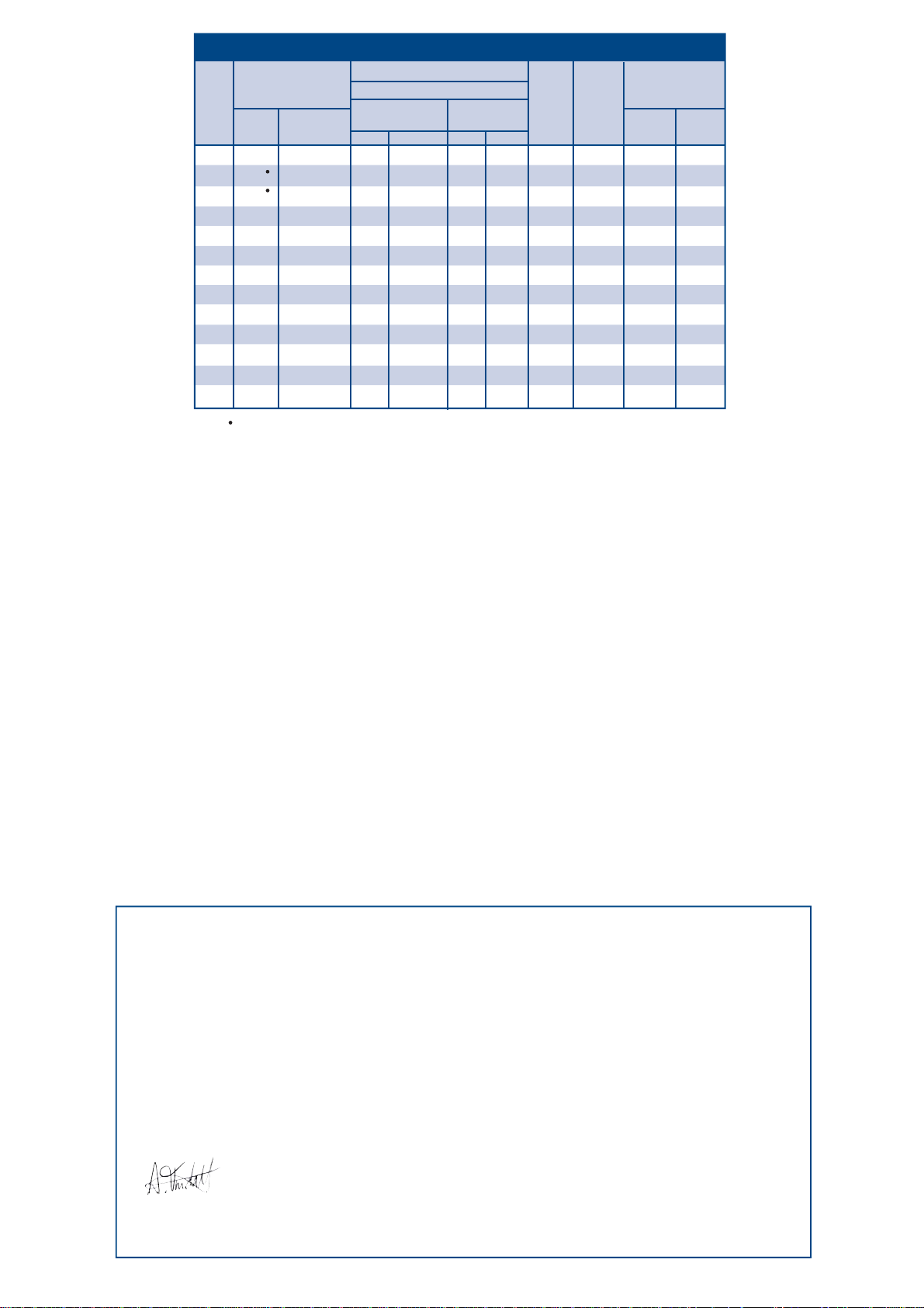
CABLE GLAND SELECTION TABLE
Cable Acceptance Details
Entry Thread Size
Size
Ref.
Metric
M16
2K
Os
M20
M20
O
A
M20
M25
B
M32
C
M40
C2
D
M50
E
M63
F
M75
G
M80
H
M90
J
M100
Sizes Os and O are available with an M16 thread size. If M16 entry is used on O
size Cable Glands the maximum cable inner sheath diameter is limited to 10.9mm.
IMPORTANT NOTE:
When used in Increased Safety applications, these cable glands may be used with braided cables where the braid and the outer sheath pass into the enclosure. The
braid must then be suitably terminated within the enclosure. Braided cable is classed as unarmoured cable in the EN/IEC 60079 series standards for Exe applications.
NPT
---
½"
½"
½" - ¾"
¾" - 1"
1" - 1¼"
1¼" - 1½"
1½" - 2"
2" - 2½"
2½" - 3"
3½"
3½"
4"
Min. Max.
10.0
13.0
19.5
25.0
31.5
42.5
54.5
67.0
67.0
75.0
Standard
Seal
3.2
3.2
6.5
Outer Sheath
8.0
8.0
11.9
14.3
20.2
26.5
32.5
42.3/44.4
54.3/56.3
65.3/68.2
73.0
77.6
91.6
Alternative
Seal (S)
Min. Max.
15.4
22.0
27.5
39.0
49.5
---
---
---
---
9.0
9.5
------
---
---
13.4
15.4
21.2
28.0
34.8
46.5
58.3
------
---
---
Compressed
23.5
23.8
23.8
24.8
25.8
28.2
29.5
40.4
38.2
40.5
41.0
41.0
41.0
Length
Maximum
39
38
39
38
41
43
44
61
59
60
54
54
54
Length
Hexagon
Dimensions
Across
Flats
19.0
24.0
24.0
30.0
36.0
46.0
55.0
65.0
80.0
95.0
106.4
115.0
127.0
Across
Corners
21.2
26.5
26.5
32.5
39.5
50.5
60.6
70.8
88.0
104.0
115.0
130.0
142.0
SCHEDULE OF LIMITATIONS - Baseefa ATEX / IECEx:
1. The cable glands are only suitable for use with xed apparatus, the cable for which must be eectively clamped and cleated elsewhere.
2. This cable gland has an operating temperature range of -60°C to +100°C.
3. A seal must be formed between the equipment and the cable gland to maintain the appropriate degree of protection against ingress of dust,
solid objects and water.
NOTES - c CSA us:
1. The cable used must have extruded sealing (solid polymeric) completely surrounding the “core” (insulation and conductor), allowing for no holes or ventilation
through the inner jacket or along the cores.
2. The 501/4** series cable gland connectors, when used in Class 1 Division 2 Classied areas, are not suitable to be interfaced with an explosion proof enclosure
containing arcing and sparking devices, unless installed in conjunction with an approved explosion proof sealing tting.
3. These glands are suitable for use with Certied Marine Shipboard armoured / unarmoured cables constructed to CSA Standard 245 and IEEE45 / IEC 600092-353
Standards, or certied equivalent), for use on Shipboards and Oshore Rigs / Platforms.
4. Must comply with Canadian Electrical Code and National Electric Code requirements for threaded entries.
5. For Exe applications, a sealing washer or thread sealant may be required between the enclosure and the gland to maintain the IP rating of the enclosure.
6. When used with unarmoured or braided cables the glands are only suitable for use with xed apparatus and the cable must be eectively clamped and cleated
elsewhere.
7. This cable gland may only be installed when temperature is above -5°C. After completion of the installation, the assembly is then suitable for -60°C to +100°C.
EU Declaration of Conformity in accordance with European Directive 2014/34/EU
Manufacturer: Hawke International
Address: Oxford Street West, Ashton-under-Lyne, OL7 0NA, United Kingdom.
Equipment: Group II Compression Cable Glands Type: 501/421
Provisions of the Directive fullled by the Equipment: Group II Category 2GD Exe IIC Gb, Exd IIC Gb, Extb IIIC Db – IP66
Notied Body for EC-Type Examination: SGS-Baseefa 1180 Buxton UK
EC-type Examination Certicate: Baseefa06ATEX0056X
Notied Body for production: SGS-Baseefa 1180 Buxton UK
Harmonised Standards used: EN 60079-0:2012+A11:2013, EN60079-1:2014, EN60079-7:2015, EN60079-31:2014
On behalf of the above named company, I declare that, on the date the equipment accompanied by this declaration is
placed on the market, the equipment conforms with all technical and regulatory requirements of the above listed
directives.
………………………………….
A. Tindall
Technical Manager
AI 307 - Issue V / Page 2 of 2
 Loading...