

Page 1
SULTAN FLOW
Acoustic Wave Technology
DRAFT
INSTRUCTION MANUAL
A higher level of performance
Page 2

Sultan Flow Series MANUAL
3
Draf t 1.2, Mar 20 09
INTRODUCTION
PROPRIETARY NOTICE
The information contained in this publication
is derived in part from proprietary and patent
data. This information has been prepared for
the express purpose of assisting operating
and maintenance personnel in the efcient
use of the instrument described herein.
Publication of this information does not convey
any rights to use or reproduce it, or to use for
any purpose other than in connection with the
installation, operation and maintenance of the
equipment described herein.
WARNING
This instrument contains electronic
components that are susceptible to damage
by static electricity. Proper handling
procedures must be observed during the
removal, installation, or handling or internal
circuit boards or devices.
Handling Procedure:
1. Power to unit must be removed.
2. Personnel must be grounded, via wrist
strap or other safe, suitable means, before
any printed circuit board or other internal
devices is installed, removed or adjusted.
3. Printed circuit boards must be transported
in a conductive bag or other conductive
container. Boards must not be removed
from protective enclosure until the
immediate time of installation. Removed
boards must be placed immediately in a
protective container for transport, storage,
or return to factory.
Comments:
This instrument is not unique in its content
of ESD (electrostatic discharge) sensitive
components. Most modern electronic designs
contain components that utilize metal oxide
technology (NMOS, CMOS, etc.). Experience
has proven that even small amounts of static
electricity can damage or destroy these
devices. Damaged components, even though
they appear to function properly, exhibit early
failure.
CONTENTS
Features
Principle of Operation 3
Open Channel Flow Principles 4
Flow Measuring Device Selection 5
Exponential Devices 6
Installation Guide 7
- Amplier
- Blanking Distance
- Point of measurement 8
Typical Application 10
Calculations & drawings
- Absolute & Ratiometr ic 11
- BS3680 umes 12
- BS3680 U-throated umes 14
- BS3680 rectangular weirs 15
- BS3680 thin plate weir 17
- Velocity area 19
- Rectangular channel 20
- Trapezoidal 21
- Round pipe 22
- Special devices 23
Unit Software
- Diagnostics 25
- Quickset 26
- Output adjustment 27
- Relay modes 29
- Flow types 30
- TX Setup 32
Flow calculation method 33
Flow table entry method 34
Totaliser mode 37
Reset mode 39
Part Numbering 52
PATENT PENDING
2
Page 3

Sultan Flow Series MANUAL
Draft 1.2, Mar 200 9
PRINCIPLE of OPERATION
The Sultan Flow measurement system
operates by transmitting an acoustic
wave signal from the transducer
towards the liquid being monitored. The
reected signal or echo is received by
the transducer and processed by the
amplier. The time between transmission
of the signal and reception of the echo
is measured, and using the speed of
sound through air, the distance from the
transducer to the liquid being monitored
is calculated.
The Sultan Flow system uses
sophisticated software to locate and
track the correct echo without being
affected by echos from xed objects
or changes in the liquid surface. When
the liquid level or surface conditions
change, the system adopts preselected
signal tracking parameters. In the event
of a total loss of signal, the system
adopts pre selected signal recovery
routines to relocate the correct liquid
level. The system employs automatic
gain control to compensate for changes
in echo amplitude due to changes in
environmental conditions. The system
has continuous current, voltage and
relay outputs. These outputs can be
programmed for fail safe conditions in
the event of a loss of signal or system
malfunction. The factory settings
are based on years of experience in
acoustically difcult applications. This
typically means that the system can
be installed and made operational in a
minimum of time.
FEATURES
• Optimized frequency selections to suit
the application environment
• Capable of monitoring liquid ow under
the most difcult conditions
• Real time diagnostic display
• Flexible, multi point or calculated scaling of display and outputs
• Suits a broad range of umes, wiers
and ow control structures
• Programmable, resettable totalizer
• Programmable pulse per ow output
• Programmable failsafe mode
• Fast acting temperature compensation
• GSM/CMDA
• Wide range of communications:
Devicenet, Goshawk, HART, Modbus,
Probus (Fieldbus & Probus PA pending)
remote setup options/cong
3
Page 4
Sultan Flow Series MANUAL
5
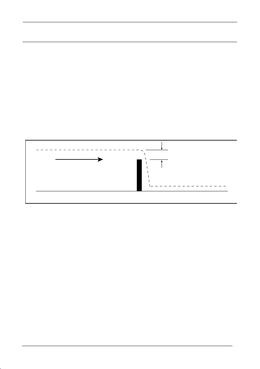
Surface of liquid
Flow
Weir
Rise above weir
increases with
flow volume
Figure 1.
Draf t 1.2, Mar 20 09
OPEN CHANNEL FLOW MEASUREMENT PRINCIPLES
Obstructions in channel cause rise in
level
An obstruction in a channel represents
a reduction of the cross-section of the
channel. Since practical liquids are essentially incompressible, the volume of
liquid owing past an obstruction must
equal the volume owing towards it. It
follows that the liquid must divert around
the obstruction
If a barrier to ow is installed across the
bottom of a channel, the liquid level rises
as it ows over it - this leads to the use
of the weir in open-channel ow meas-
urement. If the cross-sectional area of a
channel is reduced, the liquid level must
rise as it ows past - this leads to the
ume.
The height of the liquid surface above
the Weir is called the Flow Head (h). The
head is known to be related to the Vol-
ume Flowrate(q), allowing the owrate to
be calculated from measurement of the
head. The formula is of me form:
q = kh
where the exponent α is typically about
1.5 and the constant k depends upon the
channel and weir dimensions.
Different shapes of weir have been
developed to provide improved accuracy
under different conditions, but the principle is the same for all. These various
weirs have different exponents, but most
within the range of 1.3 to 1.7.
α
Flumes, in which the channel width is
narrowed have become preferred for
accuracy and robustness (eg. self scrubbing). Many ume proles have been developed, each having its advantages and
disadvantages for a given application.
A similar exponential relationship ex-
istsbetween head and owrate in these
umes,and each type has a different
exponent,commonly in the range of 1.3
to 1.8.
4
Page 5

Sultan Flow Series MANUAL
Draft 1.2, Mar 200 9
FLOW MEASURING DEVICE SELECTION
There are several exponential types of
ow measuring devices. They are:
- BS3680 umes - BS3680 Weirs
- Area Velocity - Velocity
- Special - Universal
- Linear - Curved
Flow calculations can be performed using
either absolute or ratiometric methods.
The end result will be the same, the
choice of calculation method is limited according amount of information available,
with regards to the primary measuring
device.
Ratiometric
For ratiometric calculation it is normally
sufcient to know the maximum ow at
maximum head for the device in question.
All types of primary measuring devices
can be set up with a choice of alarms.
Exponential
If you want to set-up a basic exponential
device, you then need to select the primary measuring device for your application from the following available options:
suppressed rectangular weir, cipolletti
(trapezoidal) weir, venturi ume, parshall
ume, leopold lagco ume, V notch weir
or other, for any other type of exponential
device.
BS3680 Flume
To set-up an application for a BS3680
ume, you then need to select the primary measuring device for your application from the following available options:
rectangular ume with or without hump,
U-throated ume with or without hump.
BS3680 Weir
To set-up an application for a BS3680
weir, you then need to select the primary
measuring device for your application
from the following available options:
rectangular weir, V notch 90 degree, V
notch 53 degree 8 minutes or a Vnotch
28 degree 4 minutes.
Area Velocity
To setup an application for area velocity, you then need to select the primary
measuring device for your application
from the following available options:
U-channel (circular bottom with straight
sides), rectangular channel, trapezoidalchannel or a round pipe.
Special Flow Device
To set-up an application for a special
device, you then need to select the primary measuring device for your application from the following available options:
palmer bowlus ume, H-ume or a non
BS3680 V-notch.
Universal Device
For devices which do not match any of
the above devices the application can
be setup using a universal ow calculation, to select this option choose 6. You
then need to select the primary measuring device for your application from the
following available options: linear ow or
curved ow.
Linear Flow
Curved Flow
5
Page 6
Sultan Flow Series MANUAL
7
Suppressed
Rectangular
Weir
Flow Type
Cipolletti
(Trapezoidal)
Weir
Parshall Flume
Venturi Flume
Leopold Lagco
Flume
V-Notch Weir
Other
1.50
1.50
1.50
Default = 1.55
but value can be
set as required
1.55
2.50
Value to be set
as required
Exponent
Draf t 1.2, Mar 20 09
EXPONENTIAL DEVICES
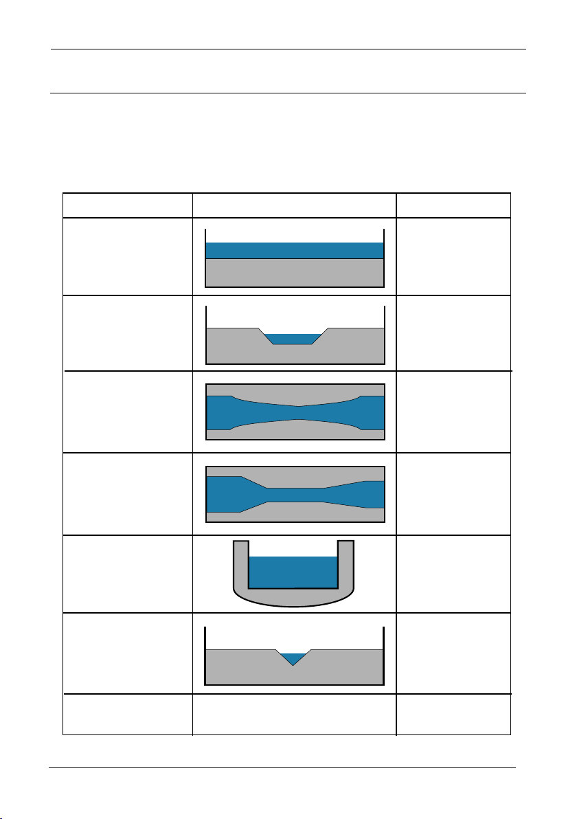
If the primary measuring device is a simple exponential device then an exponent value
is required.
Typical Exponent Values are shown below:
6
Page 7
Sultan Flow Series MANUAL
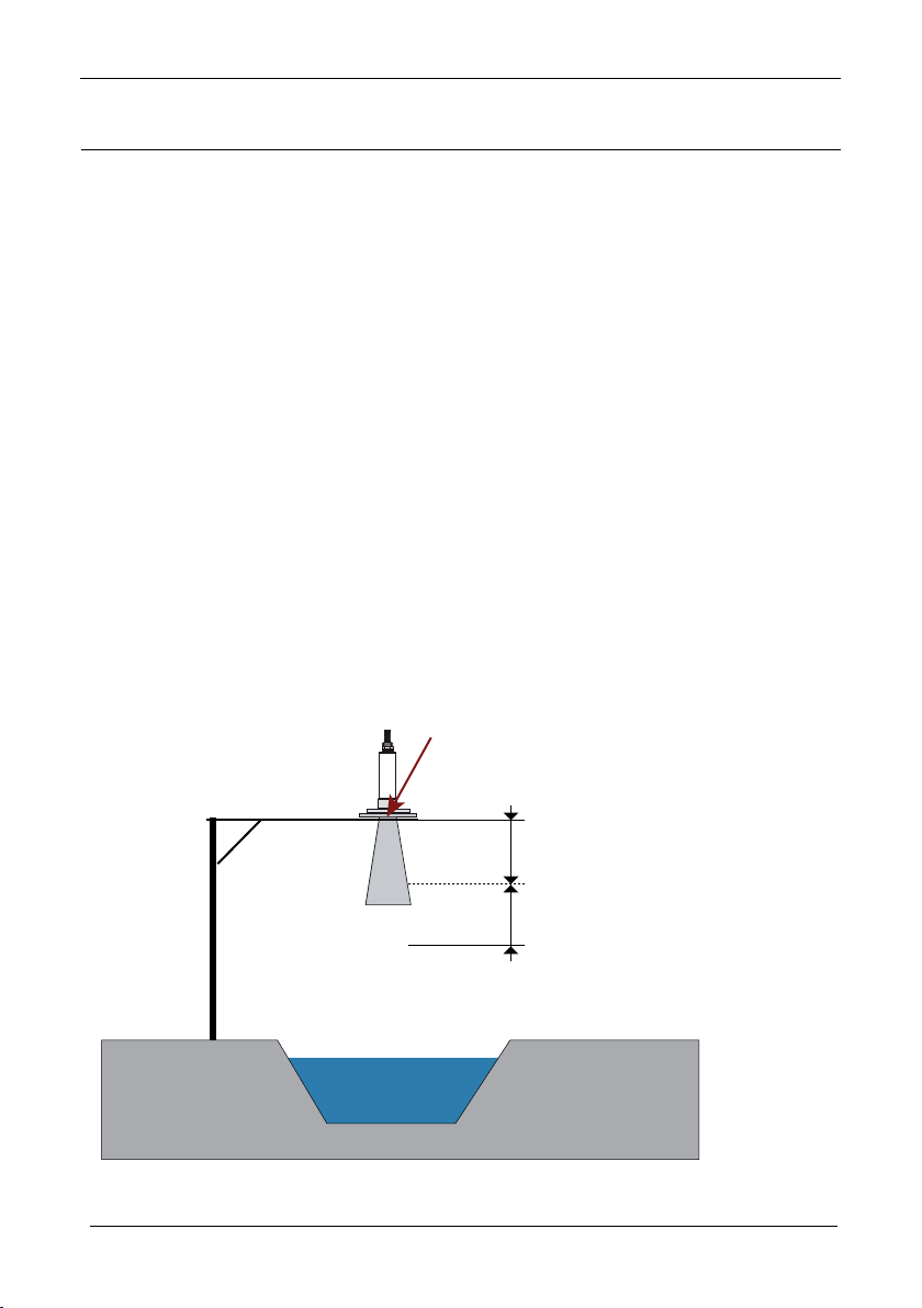
Blanking distance (450mm)
Example 20kHz flow transducer above trapezoidal weir
(not to scale)
Transducer face
+100% (total 900mm)
Draft 1.2, Mar 200 9
INSTALLATION GUIDE
AMPLIFIER
Select a suitable mounting position that
is not in direct sunlight. If necessary, utilize a sunshade. Observe the minimum
and maximum temperature limits (c-f).
Do not mount near sources of high
E.M.F. such as high current cables,
motor starters, or S.C.R. variable speed
drives.
BLANKING DISTANCE
The blanking distance is the distance
prior to the minimum measureable
distance from the face of the transducer.
When the transducer pulses it vibrates
the transducer face which can create &
detect unwanted echoes. As a result the
internal software creates a ‘blank’ zone
approximately 250-450mm (depending
on the transducers power) from the face
of the transducer.
Avoid mounting in high vibration areas
such as handrails and rotating plant. Use
rubber absorption mounts if mounting in
light vibration areas.
As a result the transducer face must always be mounted a minimum the blanking distance away from the liquid. Ideally
the blanking distance + 50-100% of this
distance (eg, for a 20kHz with a 450mm
blanking distance we would recommend
700-1000mm between the transducer
face and the liquid).
7
Page 8
Sultan Flow Series MANUAL
9
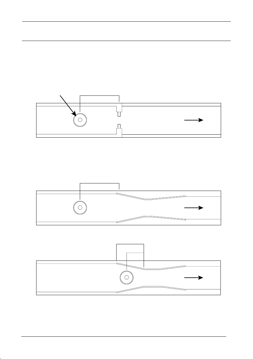
FLOW (q)
3 x HMAX
minimum
DRWG 1
FLOW (q)
150mm
DRWG 2
Venturi Flume
FLOW (q)
L
DRWG 3
Parshall Flume
2/3L
Transducer
Draf t 1.2, Mar 20 09
TRANSDUCER POINT OF MEASUREMENT
Positioning Of Sensor
For Suppressed Rectangular,Trapezoidal and V-notch weirs, the head is measured
upstream at a minimum distance of 3 times maximum head from the weir plate to ensure the surface of the liquid is not affected by turbulence or draw down. (See DRWG.
1)
In the case of a Venturi ume the point of measurement should be 150 mm upstream
from the beginning of the converging section and for a Parshall ume 2/3 the length of
the converging section upstream of the throatsection. See DRWG 2 and 3 )
8
Page 9
Sultan Flow Series MANUAL
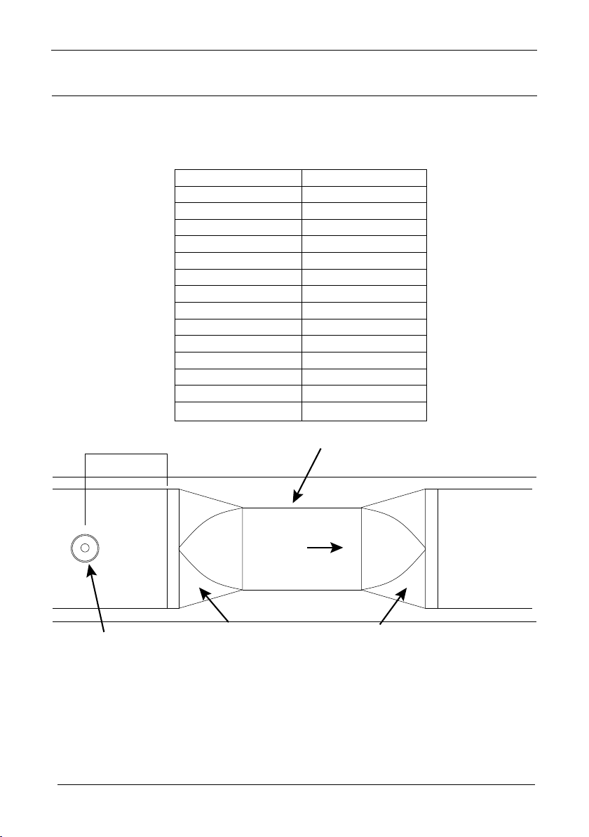
100 - 305 4 - 12 25 1.0
380 15 32 1.3
455 18 38 1.5
530 21 44 1.8
610 24 51 2.1
760 30 64 2.5
915 36 76 3.0
1065 42 89 3.5
1220 48 102 4.0
1370 54 114 4.5
1520 60 127 5.0
1675 66 140 5.5
1830 72 152 6.0
FLOW
DRWG 4
Transducer mounted
minimum blanking distance
above max. head
Point of
measurement
Throat
Converging Diverging
Flume Size
mm inches
Point of Measurement
mm inches
Draft 1.2, Mar 200 9
TRANSDUCER POINT OF MEASUREMENT
For a Leopald Lagco ume the head is measured at a point upstream of the beginning of the converging section as detailed in the table below. (See DRWG 4 )
When any other device is chosen please consult the manufacturer of the device for details of where the point of measurement should be located but ensure that it is chosen
such that the surface of the liquid is not effected by turbulence or drawdown.
9
Page 10
Sultan Flow Series MANUAL
11
Draf t 1.2, Mar 20 09
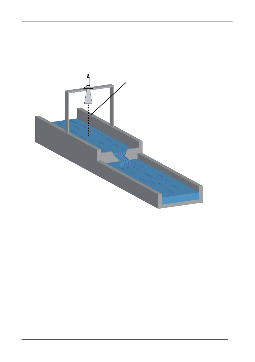
TYPICAL APPLICATION EXAMPLE
Typical Exponential Device - Trapezoidal weir
Transducer mounted minimum
blanking distance above max
head
+50% of this distance
10
Page 11

Sultan Flow Series MANUAL
Draft 1.2, Mar 200 9
11
Page 12
Sultan Flow Series MANUAL
13
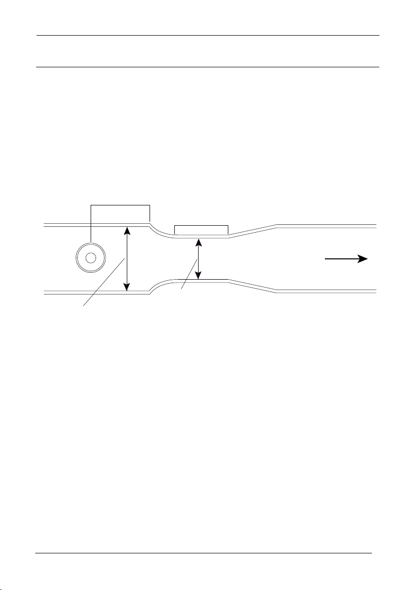
Transducer
position
Throat
length
DIM C
3-4 x hmax
DIM A
Approach width
DIM B
Throat width / diameter
Flow (q)
BS3680 flume
Draf t 1.2, Mar 20 09
BS3680 FLUMES
Point of Measurement
The transducer must be above the maximum head by at least the near blanking
distance.
For a Rectangular and U-throated ume,
the head is measured at 3 to 4 times the
maximum head upstream from the begin-
ning of the converging section, to ensure
the surface of the liquid is not effected by
turbulence.
12
Page 13

Sultan Flow Series MANUAL
Draft 1.2, Mar 200 9
BS3680 FLUMES
13
Page 14

Sultan Flow Series MANUAL
15
Draf t 1.2, Mar 20 09
BS3680 U-Throated Flume
In this example it is required to calculate
to BS3680 the ow through a U-Throated
Flume without any hump. Absolute
calculation will be used. The ow rate is
to be displayed in cubic meters/hour and
the totaliser is also to record the ow in
cubic metres.
The distance from the end of the trans-
ducer to zero ow is 1 metre and max
head is 0.4 metres, maximum ow.
The dimensions of the ume are as fol-
lows:
Approach Channel diameter
(Dim “A”) = 0.7 m
Throat diameter (Dim “B”) = 0.5 m
Throat length (Dim “C”) = 1.0 m
14
Page 15
Sultan Flow Series MANUAL
Draft 1.2, Mar 200 9
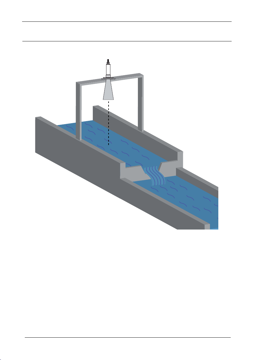
BS3680 RECTANGULAR WEIR
In this example it is required to calculate to the ow through a BS3680 Rectangular weir. Absolute calculation will be used. The ow rate is required to be displayed
in litres/minute and the totaliser is to record the ow in cubic metres.
The distance from the end of the transducer horn to zero ow is 1 metre and max
head is 0.4 metres, maximum ow.
Approach width (Dim”A”) = 0.5 m
Crest width (Dim “B”) = 0.3 m
Crest Height (Dim “C”) = 0.3 m
15
Page 16

Sultan Flow Series MANUAL
17
Draf t 1.2, Mar 20 09
BS3680 RECTANGULAR WEIR
16
Page 17
Sultan Flow Series MANUAL
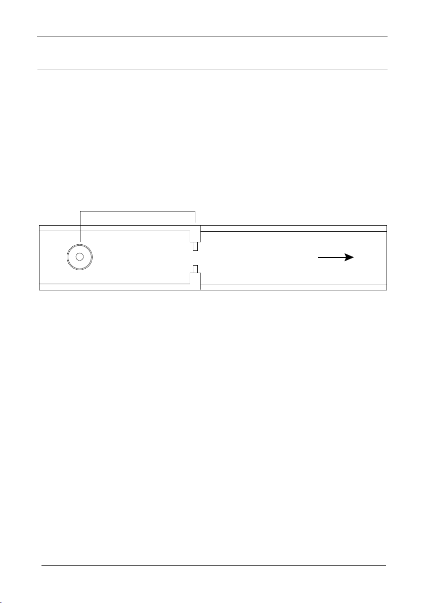
BS3680 Weir
Flow (q)
4-5 x HMAX
minimum
Draft 1.2, Mar 200 9
BS3680 Thin Plate Weirs
BS3680 Thin Plate Weirs
Point of Measurement
The transducer must be above the maximum head by at least the near blanking distance.
For a Rectangular and V-notch weirs, the head is measured at a point 4 to 5 times the
maximum head upstream from the weir plate, to ensure the surface of the liquid is not
affected by turbulence or drawdown.
17
Page 18

Sultan Flow Series MANUAL
19
Draf t 1.2, Mar 20 09
BS3680 Thin Plate Weirs
18
Page 19
Sultan Flow Series MANUAL
Draft 1.2, Mar 200 9
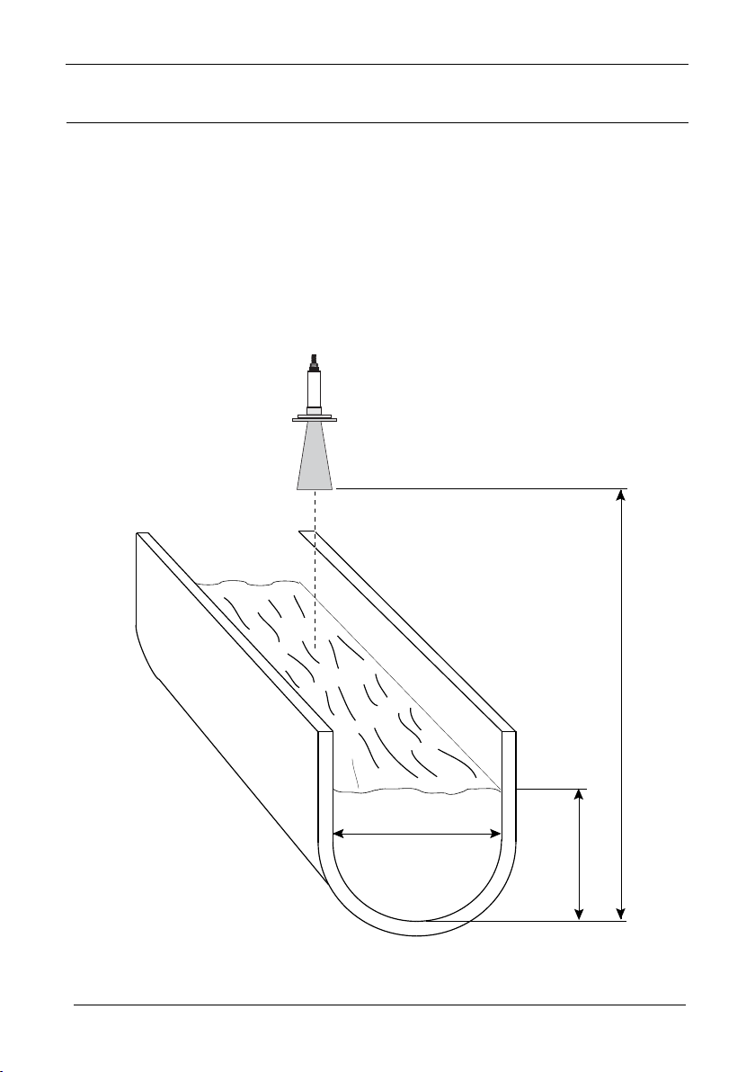
VELOCITY AREA
The calculation of ow using Velocity Area is only possible when the optional current
input is available to provide an input from a velocity sensing device which provides a
signal proportional to ow.
Point of Measurement
The transducer must be above the maximum head by at least the near blanking distance. For all Velocity/area applications the point at which the head is measured should
be chosen such that the surface of the liquid is not affected by turbulence. (See DRWG
10,11, 12 and 13)\
U-Channel
Transducer mounted
minimum blanking distance
above max head
DRWG 10
b = DIM A
Base diameter
19
Empty
distance
h
Page 20
Sultan Flow Series MANUAL
21
Draf t 1.2, Mar 20 09
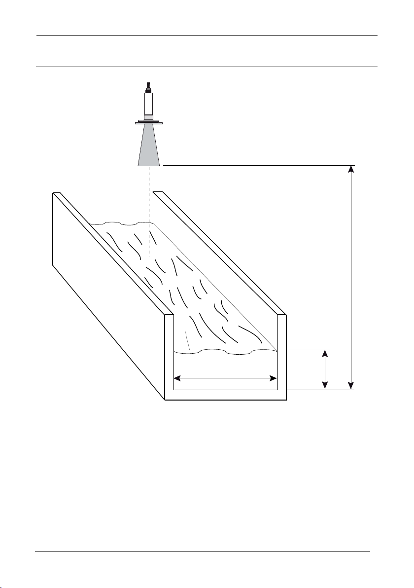
RECTANGULAR CHANNEL
Transducer mounted
minimum blanking distance
above max head
Empty
distance
DRWG 11
b = DIM A
Channel width
20
h
Page 21
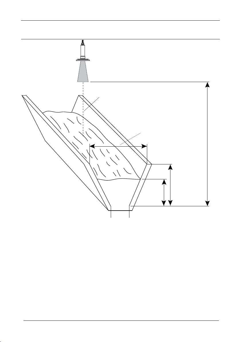
Sultan Flow Series MANUAL
Draft 1.2, Mar 200 9
TRAPEZOIDAL
Transducer mounted
minimum blanking distance
above max head
DIM A
Channel
width top
Empty
distance
DRWG 12
b = DIM ‘B’
Channel width bottom
21
h
DIM C
Channel
depth
Page 22
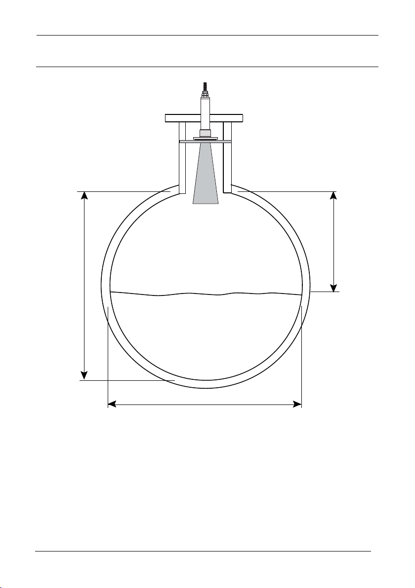
Sultan Flow Series MANUAL
23
Draf t 1.2, Mar 20 09
ROUND PIPE
Transdcuer
mounted minimum blanking
distance above
max. head
Empty
distance
If the ow calculation is to be absolute the ow will be calculated using the
formula:
q = va(h)
Where:
q = owrate
v = velocity
a(h) = area at head
22
Page 23
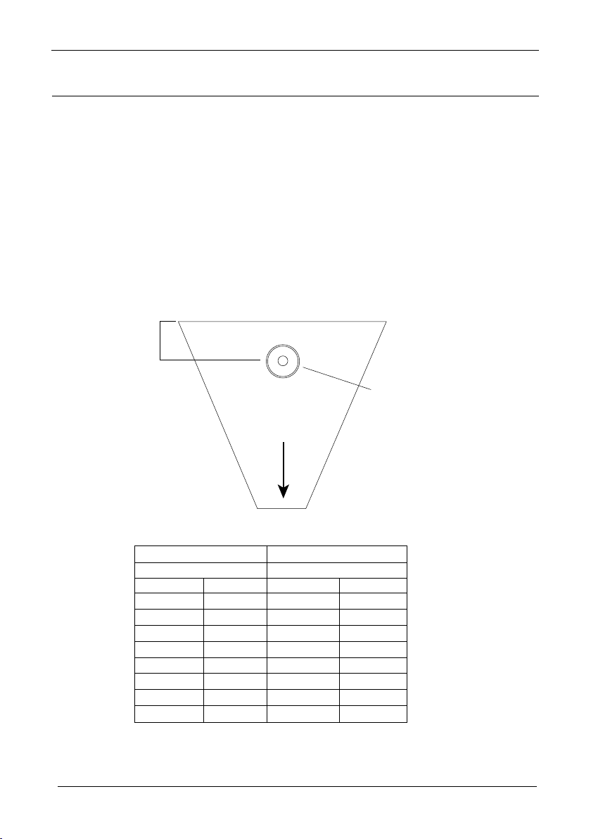
Sultan Flow Series MANUAL
137.15 4.5 40.5 16.19
15.25 0.5 4.7 1.88
23.00 0.75 6.7 2.69
30.05 1.0 9.1 3.63
45.70 1.5 13.5 5.38
61.00 2.0 17.9 7.19
76.20 2.5 22.5 9.00
91.45 3.0 27.2 10.88
Flow (q)
Point of
measurement
(see table)
Transducer mounted
minimum blanking distance
(p107) above max. head
DRWG 15
Flume size
Point of Measurement
Dim “A” P710
cm
feet cm
feet
Draft 1.2, Mar 200 9
SPECIAL DEVICES
Point of Measurement
The transducer must be above the maximum head by at least the near blanking distance.
In the case of a Palmer Bowlus ume the point of head measurement should be half
the value of Dim “A” upstream of the device.
For a H-Flume the head measurement is taken at a point downstream from the ume
entrance as detailed in the table below:
H-Flume
23
Page 24

Sultan Flow Series MANUAL
25
Draf t 1.2, Mar 20 09
SPECIAL DEVICES
V-notch angle weirs, the head is measured upstream of the weir plate at a minimum
distance of 3 timesmaximum head to ensure the surface of the liquid is not effected by
turbulence or drawdown.
Calculations
Absolute
Palmer Bowlus Flume and H-FlumeIf the ow calculation is to be absolute the ow will
be calculated using the formula: q = f(h)
Where: q = owrate
f = is an 8th degree polynomial solution for h (head)
V-Notch Angle Weir (Non BS 3680)
If the ow calculation is to be absolute the ow will be calculated using the formula:
q = Ce x 8/15 tan (theta/2) (2gn)0.5(h = kh)5/2
Where: q = owrate
Ce = discharge coefcient calculated by
theta = V-notch angle
gn = gravitational acceleration
h = head
kh = compensated head
RATIOMETRIC
Palmer Bowlus Flume and H-FlumeIf the ow calculation is to be ratiometric the ow
will be calculated using the formula: q= qcalx f(h)/f(hcal)
Where: q = owrate
qcal=owrate at maximum head
f (h) = a polynomial solution for h (head)
f(hcal) = a polynomial solution for hcal (maximum head)
V-Notch Angle Weir (Non BS 3680)
If the ow calculation is to be ratiometric the ow will be calculated using the formula:
q= qcal(h+kh/hcal+kh)2.5
Where: q = owrate
qcal = owrate at maximum head
h = head
kh = compensated head
24
Page 25
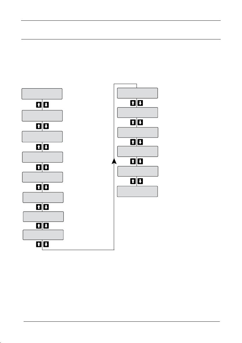
Sultan Flow Series MANUAL
5116.4562G
9762.0LH
25/02/10
9762.0LH
12:04:52
9762.0LH
Head 1.299m
9762.0LH
TX 1
9762.0LH
Failed
9762.0LH
WinFw 15
9762.0LH
WinBk 0.2
9762.0LH
Noise 1.9%
9762.0LH
Rec Gn 0.0%
9762.0LH
Gain 94.8%
9762.0LH
E Size 0.00V
9762.0LH
Echo .......
9762.0LH
Flow
9762.0LH
Draft 1.2, Mar 200 9
DIAGNOSTICS
During unit operation the units diagnostics & current settings are displayed and can be
accessed using the UP DOWN arrows
25
Page 26
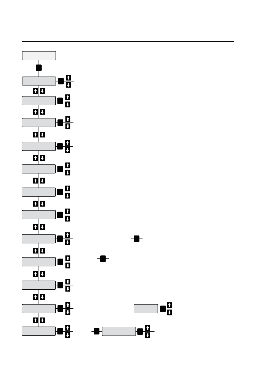
Sultan Flow Series MANUAL
27
Quickset
CAL
Dispmode
Head
Head %
Inches
Feet
Gallon
M Litres
Litres
Day
Hour
RationMtr
Absolute
Rec flume
Rec weir
V notch
Enable
Disable
Yes
No
Cube ft
Cube mtr
Minute
Second
Exp
Flow tbl
Space
Flow
Meter
Cenmeter
CAL
CAL
CAL
Head Unit
Lo Level
Hi Level
Vol Unit
FlowType
Total Mode
ClockSet
1:SenAdd
FailSafe
Time Unit
FlowMeth
CAL
CAL
CAL
CAL
CAL
CAL
CAL
CAL
CAL
Measured medium low point
Measured medium high point
CAL
1:TxAdds
CAL
1-250 1-250
20.00mA
4.00mA
LstKnown
20.20mA
3.80mA
3.50mA
FailTime
CAL
CAL
0-385
seconds
CAL
Go to ‘Totaliser’ page
Draf t 1.2, Mar 20 09
QUICKSET
See Flow Types
26
Page 27
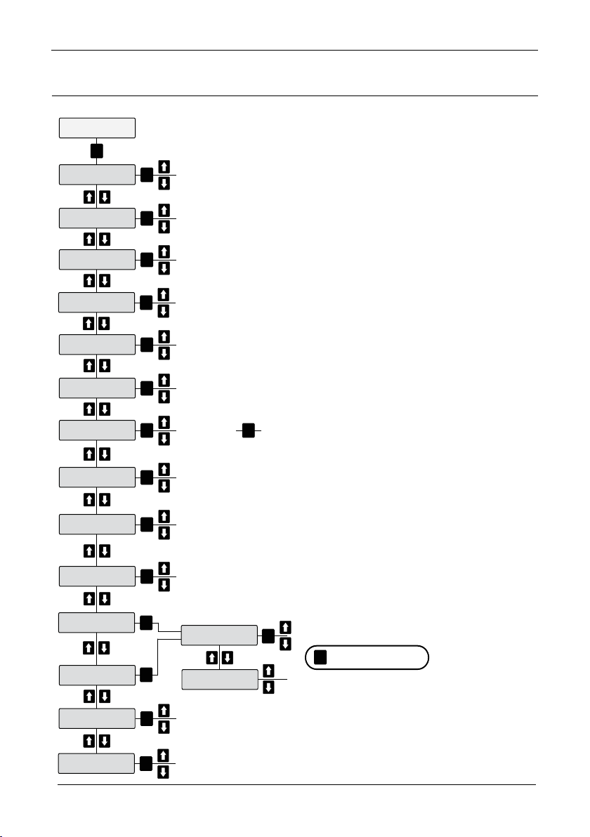
Sultan Flow Series MANUAL
Output Adj
CAL
FillDamp
Adjust fill damping
CAL
EmtyDamp
Adjust empty damping
CAL
4mA Adj
Adjust 4mA output reading
CAL
20mA Adj
Adjust 20mA output reading
CAL
Analog
Invert the 4-20mA output
to high/low or low/high
CAL
Simulate
Simulate 4-20mA output change
CAL
Comms Type
Devicenet
HART
Profibus
Modbus
CAL CAL
Go to ‘Comms Types’ on page
Rly Mode 1
See ‘Relay Modes’ on page
CAL
MinTemp
MinTempTime
MinTempDate
MaxTemp
MaxTempTime
MaxTempDate
FlowMin
FlowTime
FlowMinDate
FlowMax
FlowMaxTime
FlowMaxDate
FlowMin24
FlowMinTime
FlowMax24
TempLogData
Displays:
CAL
FlowLogData
Displays:
CAL
TotalLogData
Ajust log time
CAL
StartLogData
Log Time
CAL
01: 01/01/10
Displays logged data
CAL
LCD Light
LCD backlight On/Off
CAL
HART PV Sel
Select HART PV:
Totaliser / Flow / Level
CAL
RUN
Returns to Menu
Draft 1.2, Mar 200 9
OUTPUT ADJUSTMENT
12345
27
Page 28
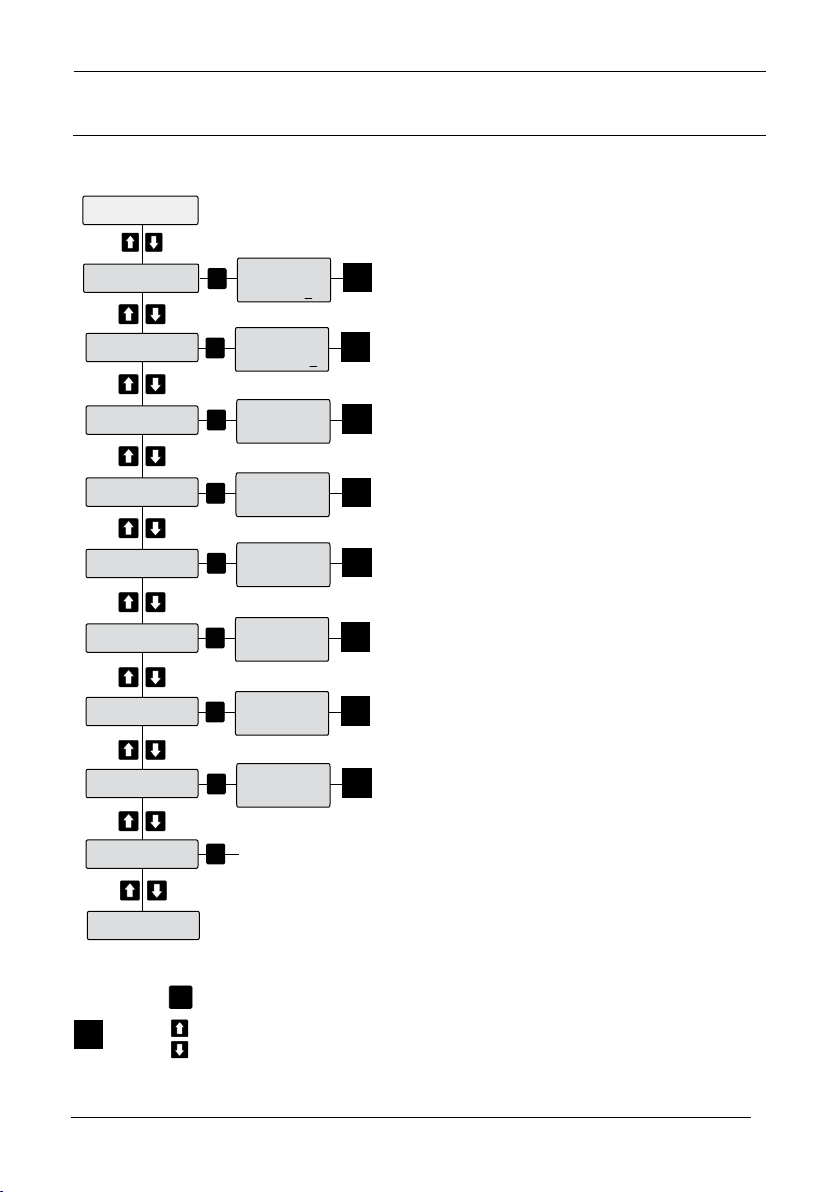
Sultan Flow Series MANUAL
29
Relay Modes
1-5
DEN Flow
DEN Head
EN Head
FS
EN Temp
EN Flow
Time
Den Temp
Rly 1 S1
2555.5 L
Press to cycle digit 0-9
Press to cycle between units
CAL
Rly Mode 1
Totaliser
CAL
1
1
CAL
1
Rly 1 S1
12:34:56*
CAL
1
Rly 1 S1
17.3C
CAL
1
Rly 1 S1
17.3C
CAL
1
Rly 1 S1
22.3%
CAL
1
Rly 1 S1
32.3%
CAL
1
Rly 1 S1
2.632m
CAL
1
Rly 1 S1
5.235m
OFF
Fail Safe
CAL
Draf t 1.2, Mar 20 09
RELAY MODE ADJUSTMENT
28
Page 29
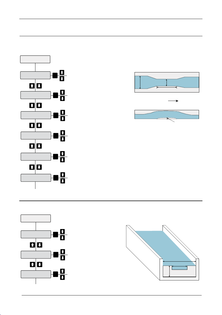
Sultan Flow Series MANUAL
Rec Flume
Throat b
AWidth B
Hump P
Throat L
Rough Ks
Avg Temp
Returns to Quickstart
Width of flume throat
CAL
Flow
b
B
L
P
Width of flume channel
CAL
Length of flume throat
CAL
Height of flume hump
(if applicable)
CAL
Approximate Constant (consult
flume manufacturer)
CAL
Average ambient temperature
CAL
Example of rectangular flume
Top
Side
Rec Weir
CWidth b
Width of weir
CAL
AWidth B
CHeight P
Width of channel
CAL
Height of weir
CAL
Returns to Quickstart
b
B
P?
Example of rectangular weir
Draft 1.2, Mar 200 9
FLOW TYPES
Rectangular Flume
Rectangular Weir
29
Page 30
Sultan Flow Series MANUAL
31
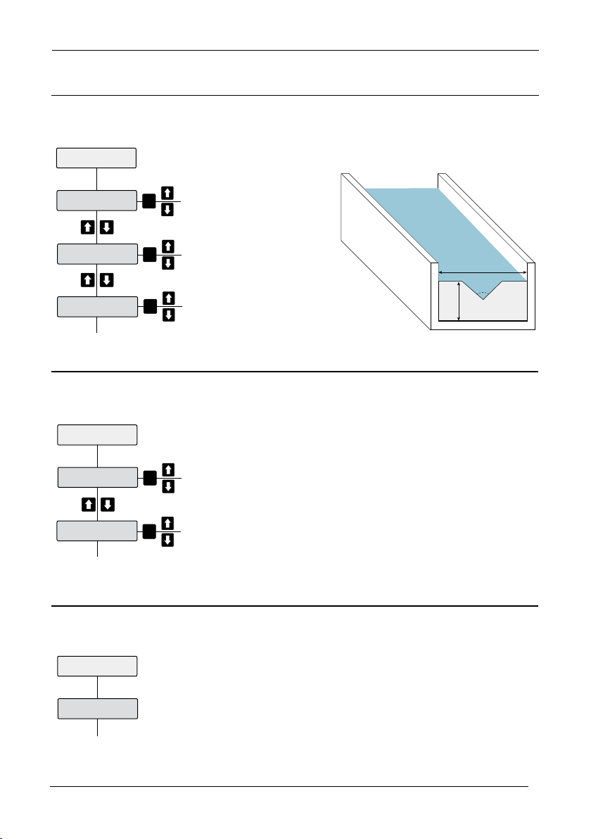
V Notch
AWidth B
Width of weir/channel
CAL
CHight P
Angle
Height of channel
CAL
V Notch angle in degrees
CAL
B
P?
Example of V notch weir
Angle
o
EXP
Exponent
Exponent
CAL
K Factor
K Factor
CAL
Returns to Quickstart
Returns to Quickstart
Flow Tbl
Flow Tbl
Returns to Quickstart
Draf t 1.2, Mar 20 09
V Notch Weir
Exponent
Flow Tbl
30
Page 31
Sultan Flow Series MANUAL
RUN
RUN
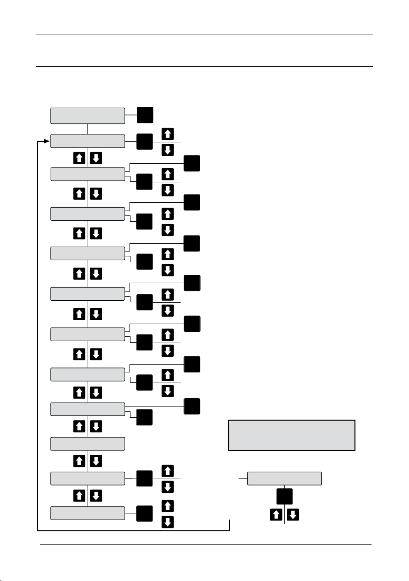
TX Set Up
Adjust Gain Gn. Press CAL to initiate single pulse.
Distance to echo will be shown
Gain 29.7%
Gain Step 21.6%
Dist Step 0.7m
Threshold 0.4V
Blanking 0.25m
Empt Dist
Temp Trim
Dist Trim
CAL
RUN
Velocity
Map Dist
Map Used
CAL
CAL
Adjust Map Used
CAL
Adjust Map Dist
Map Echo
CAL
Map Echo YES / NO
CAL
RUN
CAL
RUN
CA L
CAL
CAL
CAL
CAL
RUN
Adjust Gain Step Gn. Press CAL to initiate single pulse.
Distance to echo will be shown
Adjust Distance Step. Press CAL to initiate single pulse.
Distance to echo will be shown
Adjust Threshold Voltage. Press CAL to initiate single pulse.
Distance to echo will be shown
Adjust Blanking. Press CAL to initiate single pulse.
Distance to echo will be shown
RUN
Adjust Empt y Disance. Press CAL to initiate single pulse.
Distance to echo will be shown
Adjust Temp. Press
CAL
to initiate single pulse.
Distance to echo will be shown
*Press RUN twice to revert to
normal operation
Draft 1.2, Mar 200 9
SECTION 8
TX SETUP
DISPLAY:
31
Page 32

Sultan Flow Series MANUAL
33
Draf t 1.2, Mar 20 09
SECTION 4
FLOW CALCULATION METHOD
This section enables the user to choose
from two different ow calculation methods:
a.Exponential Flow Method
b.Flow Table entry Method
a.Exponential Flow Method
usage:for umes and weirs
To use this method,the user needs to
know:
*The weir / ume exponent
*The maximum ow
There is provision for entering the Low
Flow cutoff
Figure,although this is not manadatory.
32
Page 33

Sultan Flow Series MANUAL
Draft 1.2, Mar 200 9
SECTION 4b
FLOW TABLE ENTRY METHOD
The ow entry method can only be
achieved via GosHawk Software.
Requirements:
A. GosHawk Software
B. PC platform running Windows XP
C. USB to Sultan Amplier interface
Connect the Sultan Amplier, interface
and PC
Start the GosHawk communications
program
From the “SETUP” drop down menu
select “ow”
A window will open up showing the “Universal Method” data entry screen
Data Entry:
a.required parameters
b.calculation
c.ow table parameters
a.required parameters
low level
high level
33
Page 34

Sultan Flow Series MANUAL
35
Draf t 1.2, Mar 20 09
SECTION 4b
b.calculation
volume unit
time unit
maximum ow
c. The ow table appers on the right hand
side of the Window
Entries are to be made from the bottom
of the table
The rst entry (1) must have a value of
zero head(m)
The last entry (2-32) must be the maximum head value calculated as the High
level
Minus the Low level
A minimum of two points need to be
entered.
A maximum of 32 points can be entered.
After completion of data entry,the parameters can be downloaded to the
Sultan Flow Amplier by clicking on the
“Write Flow” button
The ow parameters can be read back
from the Amplier by clicking on the
“Read Flow” button
Activation:
The Sultan Flow unit now has the data
needed to calculate ow based on the
Flow table method.
Activating the table method is achieved
as follows:
34
Page 35

Sultan Flow Series MANUAL
Draft 1.2, Mar 200 9
SECTION 4b
FLOW TABLE METHOD
Activating the table mthod is achieved as lows:
DISPLAY:
35
Page 36
Sultan Flow Series MANUAL
37
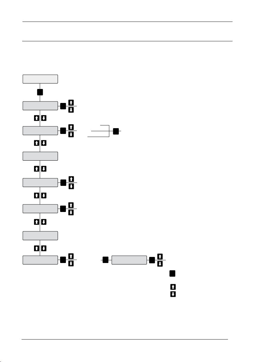
Gallon
M Litres
Litres
Vol-Time
Time
Vol
Off
Total Mode
Total Unit
Reset Mode
Totaliser
Total Clear
Totaliser M
TotM Clear
Max Interval
CAL
CAL
Cubic ft
Cubic mtr
CAL
CAL
CAL
Yes
No
CAL
Yes
No
CAL
Enable
Disable
CAL
Max Time
CAL
00:00:00 to
23:59:59
cycles between
hour/minute/second.
adjusts digit.
CAL
Draf t 1.2, Mar 20 09
TOTALISER
When Totaliser is enabled it measures the average ...
36
Page 37
Sultan Flow Series MANUAL
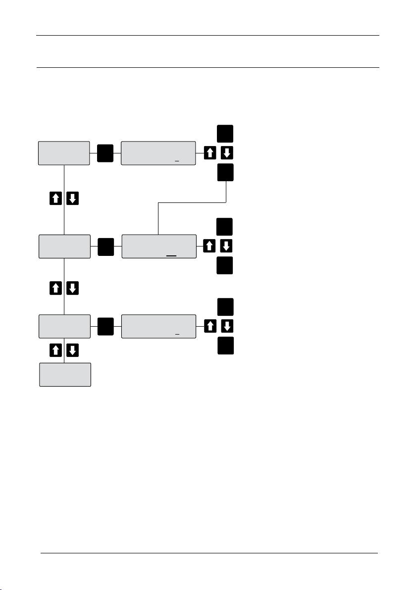
VOL: 1 2 3 4 5
1 2 3 4 5 .1 2 3 4 CM
CAL
VOL TIME
TIME
VOL
OFF
CAL
Cycles between digits
Adjusts digit value
RUN
Moves to next menu
TIME
12:34:56
CAL
Cycles between digits
Adjusts digit value
RUN
Moves to next menu
CAL
VOL: 1 2 3 4 5
1 2 3 4 5 .1 2 3 4 CM
CAL
CAL
Cycles between digits
Adjusts digit value
RUN
Moves to next menu
Draft 1.2, Mar 200 9
RESET MODE
Resets the Totaliser at the Volume setting and/or the time setting.
37
Page 38

Sultan Flow Series MANUAL
39
TOTALISER
0.0000FT
Draf t 1.2, Mar 20 09
SECTION 5.3
TOTALISER
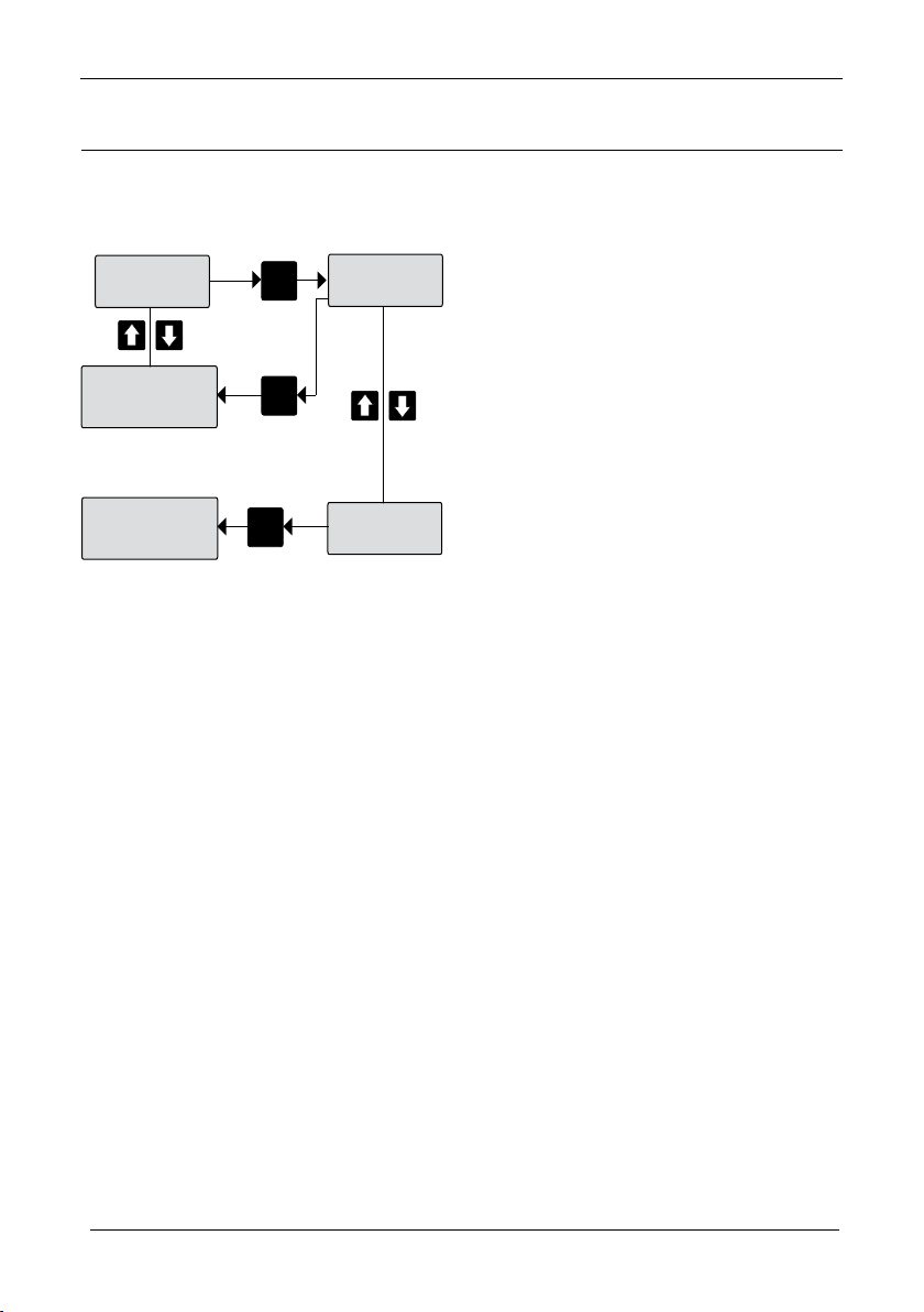
The display shows the Totalised value of ow in the units set in section 5.1 “Total Unit”
DISPLAY:
Resettable: YES
Reset Methods:
1. Manually via “Total Clear” SECTION 5.4
2. Automatically via “Reset Mode” SECTION 5.2
38
Page 39
Sultan Flow Series MANUAL
TOT CLEAR
NO
CAL
TOT CLEAR
YES
TOTALISER M
999.99FT
TOT CLEAR
NO
CAL
TOTALISER M
000.00FT
CAL
Draft 1.2, Mar 200 9
SECTION 5.4
MANUAL TOTALISER CLEAR FUNCTION “TOT CLEAR”
DISPLAY:
39
Page 40

Sultan Flow Series MANUAL
41
TOTALISER M
000.00FT
Draf t 1.2, Mar 20 09
SECTION 5.5
MASTER TOTALISER DISPLAY “TOTALISER M”
The display shows the total accumulated ow in the units set in the Totaliser unit (“Total
Unit”) SECTION 5.1.
It accumulates data regardless of the reset state of the standard Totaliser (SECTION
5.3)
DISPLAY:
Resettable: YES
Reset Method:
Manual Only
See SECTION 5.6 “TOT M Clear”
40
Page 41
Sultan Flow Series MANUAL
TOTM CLEAR
NO
CAL
TOT CLEAR
YES
MAX INTERVAL
ENABLE
TOTM CLEAR
NO
CAL
CAL
Draft 1.2, Mar 200 9
SECTION 5.6
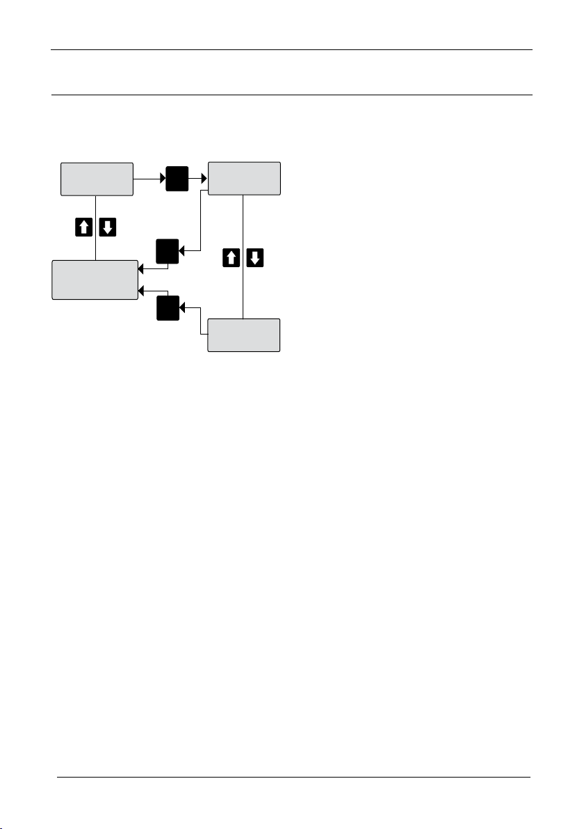
MANUAL MASTER TOTALISER CLEAR FUNCTION “TOT M CLEAR”
DISPLAY:
41
Page 42
Sultan Flow Series MANUAL
43
MAX INTERVAL
ENABLE
CAL
CAL
MAX TIME
12:34:56
CAL
MAX TIME
12:34:56
0-24
CAL
MAX TIME
12:34:56
CAL
MAX TIME
12:34:56
0-59
0-59
CLOCKSET
NO
Draf t 1.2, Mar 20 09
SECTION 5.7
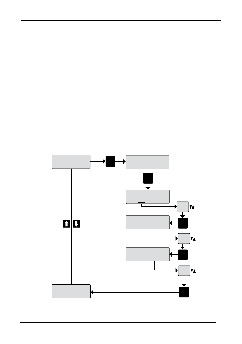
MAXIMUM INTERVAL
This function sets a time limit for updating the totalised ow from an estimated value,
when the unit is in “CAL” or any other non measurement mode.
Non measurement mode: “NMM”
1. If NMM time is less than the Max Interval then the Totaliser will be updated with the
estimated value.
2. If NMM time is more than the Max Interval then the Totaliser will not be updated with
the estimated value.
The unit estimates the ow in the NMM period by averaging the ow values just prior to
and just after the end of period.
DISPLAY:
42
Page 43
Sultan Flow Series MANUAL
RlyMoD 1
OFF
CAL
RlyMod 1
TOTALISER
RlyMod 1
TIME
RlyMod 1
DEN FLOW
RlyMod 1
EN FLOW
RlyMod 1
DEN HEAD
RlyMod 1
EN HEAD
RlyMod 1
FS
Draft 1.2, Mar 200 9
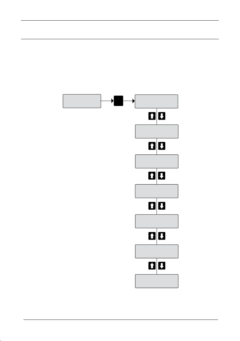
SECTION 5.8
ADDING A REMOTE DISPLAY
Apart from the on-board Totaliser functions, the unit also provides one relay output for
driving a remote Totaliser.
SETTING UP THE REMOTE TOTALISER SYSTEM
The Relay bank is accessed from the Output Menu.
DISPLAY:
43
Page 44
Sultan Flow Series MANUAL
45
CAL
CAL
TIME
12:34:56
TIME
12:34:56
0-23
CAL
TIME
12:34:56
CAL
TIME
12:34:56
0-59
0-59
DATE
12:34:56
SEC 6.2
Draf t 1.2, Mar 20 09
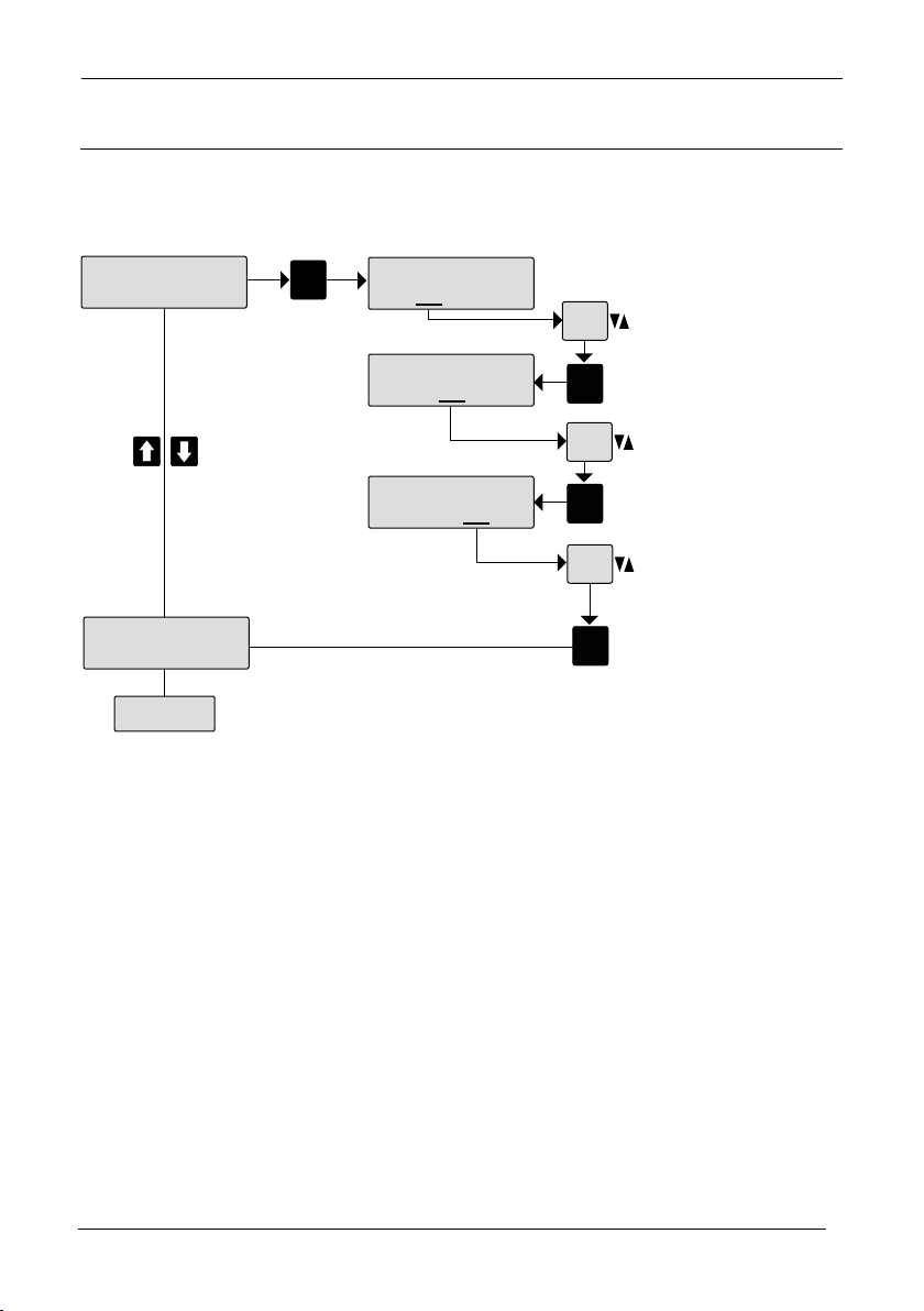
SECTION 6.1
REAL TIME CLOCK SETTING
DISPLAY:
44
Page 45
Sultan Flow Series MANUAL
CAL
CAL
DATE
01/02/03
DATE
01/02/03
0-31
CAL
DATE
01/02/03
CAL
DATE
01/02/03
0-12
0-99
FAILSAFE
20.00mA
Draft 1.2, Mar 200 9
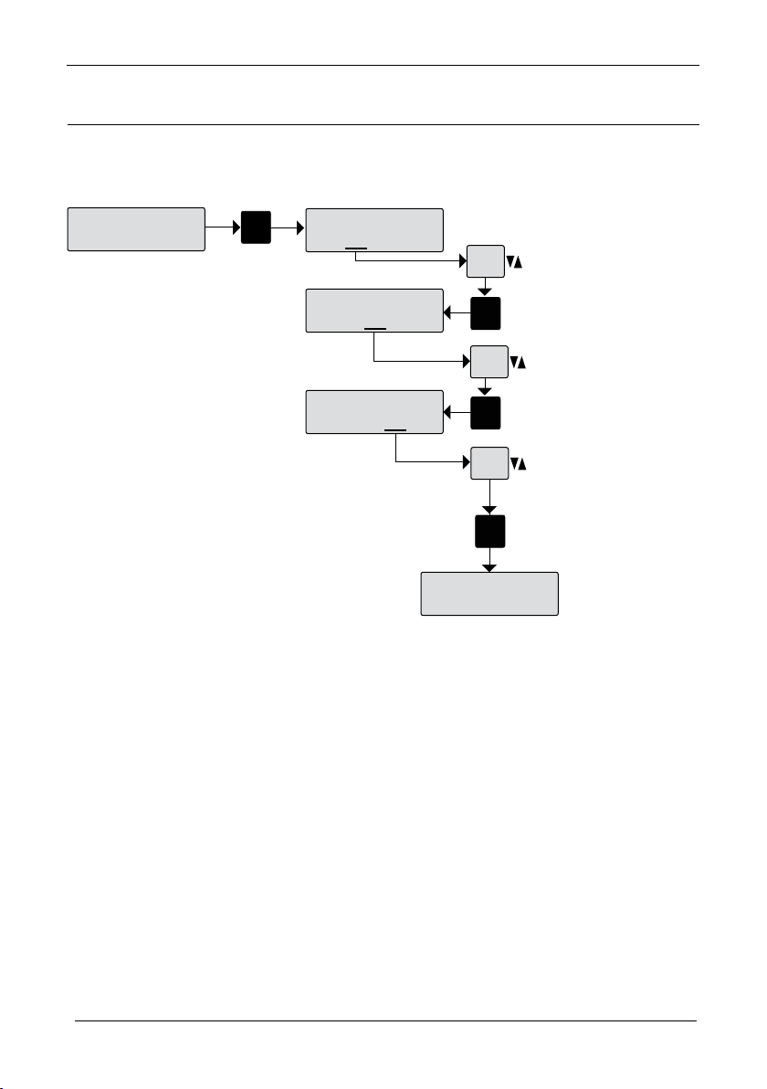
SECTION 6.2
SETTING THE DATE COMPONENT OF THE REAL TIME CLOCK
DISPLAY:
45
Page 46
Sultan Flow Series MANUAL
47
*Press RUN twice
to revert to
normal operation
Adjust Window Width
Tx Setup
Unlock 195
QuickSet
Can only be entered by
entering Unlock 195
then press CAL
Output Adj
Tracking
RecovMax
Window
Wind Fwd
Wind Back
Conrm
Hold
Tx Charge
Sens Adds
Movement
CAL
CAL
RUN
CAL
CAL
CAL
CAL
CAL
CAL
CAL
CAL
CAL
CAL
CAL
CAL
CAL
CAL
CAL
CAL
Adjust Forward Movement of window
Adjust Conrm Number
Adjust Hold Number
Draf t 1.2, Mar 20 09
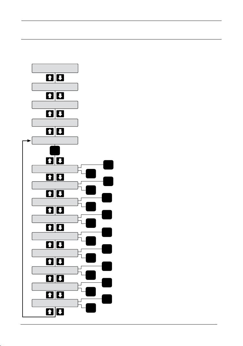
SECTION 9
TRACKING
DISPLAY:
46
Page 47
Sultan Flow Series MANUAL
Flow Type
Rec Flume
CAL
Flow Type
Rec Flume
Total Mode
Disable
Flow Type
Rec Weir
Flow Type
V-Notch
Flow Type
EXP
Flow Type
Flow tbl
CAL
Throat b
0.001m
Awidth B
0.001m
Throat L
65.535
Hump P
65.535
CAL
Throat b
0.001m
0-65.535
CAL
CAL
Awidth
0.001
CAL
0-65.535
CAL
Throat L
0.001m
0-65.535
CAL
CAL
Hump P
65.535
0-65.535
Rough Ks
2.0000
CAL
CAL
Rough Ks
2.0000
0.0003 to 2.0000
Avg Temp
19.9c
CAL
CAL
Avg Temp
19.9c
160c to -50c
Max Flow
1.0000ms
Lo Cuto
0.0000ms
Draft 1.2, Mar 200 9
47
Page 48
Sultan Flow Series MANUAL
49
Draf t 1.2, Mar 20 09
Sultan AW Flow Remote Electronics
Model
AWFR234 Remote Open Channel Flow Transmitter
Housing
S Standard polycarbonate electronics housing
P Panel Mount Housing
Power Supply
B 24 VDC standard
C 48 VDC
U Universal AC power supply (90-260 VAC input) or 24 VDC
Output Conguration (PC comms Goshawk standard)
S Switch only. 5 relays
X 4-20mA analogue output module, includes Modbus comms
I HART Isolated 4 wire
W Modbus Comms only
P Probus DP
E Ethernet
D Devicenet
Z Special Request
Internal HawkLink Modem (not available with
ATEX 0/20 approval)
X Not Required
G2 GSM Frequency 800/1900 MHz/19200 Baud for USA,
Canada, Argentina, Chile
G4 GSM Frequency 900/1800 MHz/19200 Baud for
Australia, Europe, Chile
Approval Standard
X Not Required
Position Unit / Crane Master Options
for Sultan 234 Only
X Not required
AWFR234
S B X G4 X X
48
Page 49

Sultan Flow Series MANUAL
Draft 1.2, Mar 200 9
Frequency
• 20kHz, 30kHz, 40kHz, 50kHz
Operating Voltage
• 12 - 30Vdc (residual ripple no greater than
100mV)
• 90 - 265Vac 50/60Hz
• 48Vdc,48Vac-90Vac 50/60Hz
Power Consumption
• <3W @ 24Vdc
• <10VA @ 240Vac
• <4W @ 48Vdc, <7VA @ 48Vac – 90Vac.
Analog Output
• 4 -20mA (750 ohms @ 24Vdc User supply,
250 ohms internally driven)
Communications
• Goshawk, HART, Modbus, Probus DP,
DeviceNet
(Foundation Fieldbus & Probus PA pending)
Muliti Drop mode can address 1 -250 units over
4 wire
Relay Outputs: (5)
• Form ‘C’ (SPDT) contacts, rated 0.5A at
240Vac non-inductive.
• All relays have independently adjustable
dead bands.
• Remote failsafe test facility for one relay.
Blanking Distance
• 50kHz = 0.25 m (10”)
• 40kHz = 0.30 m (12”)
• 30kHz = 0.35 m (14”)
• 20kHz = 0.45 m (17”)
Maximum Range
• 50kHz 5 m (16ft)
• 40kHz 7 m (22ft)
• 30kHz 10 m (33ft)
• 20kHz 20 m (65ft)
Resolution
• 1 mm (0.04”) 50, 40, 30,20 kHz
Electronic Accuracy
• +/- 0.25% of maximum range
Operating Temperature
• Amplier -40°C (- 40°F) to 80°C (176°F)
• Transducer -40°C (-40°F) to 80°C (176°F)
Transducer/Amplier Separation
• up to 1000m (3281ft) using appropriate
RS485 cable
Cable
• 4 conductor shielded twisted pair instrument
cable.
Conductor size dependent on cable length.
BELDEN 3084A, DEKORON or equivalent.
Max: BELDEN 3084A = 500m (1640 ft)
Max: DEKORON IED183AA002 = 350m (980 ft)
Maximum Operating Pressure
• +/- 7.5 PSI (+/- 0.5 Bar)
Beam Angle
• 7.5° without focaliser 50kHz/40kHz /30kHz
• 4° with focaliser 50kHz/40kHz
• 6° with focaliser 30kHz/20kHz
Display
• 2 line x 12 character alphanumeric LCD
• LED Back-lit display
Memor y
• Non-Volatile (No backup battery required)
• >10 years data retention
Enclosure Sealing
• Remote Electronics IP65 (Nema 4x)
• Remote Transducer IP68
Cable Entries
• Remote: 3 x 20mm, 1 x 16mm knock outs.
Mounting
• 6” Multit ANSI/DIN/JIS Flange
Typical Weight
Sultan AW System with appropriate ange
and cone
Conguration kg / lb
R6 Remote system with 6m cable 1 / 2.2
R15 Remote system with 15m cable 3 / 6.6
R30 Remote system with 30m cable 6 / 13.2
R50 Remote system with 50m cable 10 / 22.0
49
Page 50

Contacts
Rev Draft v1.1 2009
Hawk Measurement Systems (Head Ofce)
15-17 Maurice Court
Nunawading VIC 3131
Australia
Phone: +61 3 9873 4750
Fax: +61 3 9873 4538
[email protected]
www.hawkmeasure.com
Global representatives on
www.hawkmeasure.com
Part no. DOC-XX-MAN
Hawk Measurement
3911 W. Van Burren STE B-7
Phoenix, Arizona 85009
USA
Phone +1 888 HAWKLEVEL (1-888-429-5538)
Fax: +1 602 353 1707
[email protected]
www.hawkmeasure.com
Represented by:
 Loading...