

Page 1
Sultan Sonar Manual Rev 1.0
A Higher Level of Performance
Manual
Sultan
Acoustic Wave Series
Level, Flow, Positioning, Collision Protection
For more information, please visit >
www.hawkmeasure.com
Page 2
Table of Contents
Sultan Acoustic Wave Series
Contents
System Components 3
Remote Amplifier 3
Panel Mount Remote A mplif ier 3
Flange and Cone Assem bly 4
AWR23 4 Remote A mplif ier 4
Wirin g The Uni t 5
Sultan Re mote Units 5
Sultan Integral U nits 6
Sultan Panel Mount Units 7
Sultan S MART Units 8
Wirin g 4-20mA Ou tput 9
SOURCI NG Type Output 9
SINKI NG Type Output (also 2 wire loop powered) 9
Junction Box / Transducer Cabl e Extension 9
Wirin g Transducer for A nti Cro sstalk 10
Wiring for Anti C rosstalk 10
Digital Output Pulse Sequencing 11
Incorrect Mounting 12
Corre ct Mounting 13
Installation Guide 14
Installation Examples 16
Sett ing Your System 17
Dimensions 18
Integral Units 18
Remote Transducers 18
Flanges 19
Remote Amplifier 19
Minimum Measurement Range 20
Wiring Diagrams 21
AWR Remote Transmitter 21
AWI Integral Transmitter 21
Diagnostics & Sof twar e Over view 22
Quickset Flow Ch art 23
Quickset Paramete rs 2 4
Quickset 24
Application Types 25
Displ ay Mode 27
Average L evel 2 8
Differential Level 29
Advanc ed Setup Menu 30
Advanced Parameters 31
Output Adjustment Setup Menu 32
Output Adjustment Parameters 33
Relay Sw itch Actions 34
Relay 1 - 5 34
Comm Types S etup M enu 35
Modbus 36
DeviceNet - Se tup & Par ameters / Wiring 3 8
Probu s - Setup & Parameters 39
PC Comms - GosHa wkII 40
Conver ting 2 34 Wire to 2 Wire L oop 41
Troubleshooting 42
Displays Distance 43
Output 44
Unit Volt age Sp ecs & Checks 45
Remote & Integral 45
Troubleshooting 46
Error Codes 01 - 04 46
Technical Suppor t 47
Part Numbering 48
Sultan Remote Transmitter 48
Sultan Re mote Transduc er 3” and 3.5” 49
Sultan Re mote Transduc er 2” Version 50
Sultan Integral 3 ” and 3.5” 51
Sultan Integral 2 ” 52
Flange Selection 53
Cone Selection 53
Transducer / C one / Flange Combination Table 54
Accessories 54
Specications 55
Speci cat ions / A pprova ls & Cer tication 56
2
Page 3
System Components
Sultan Acoustic Wave Series
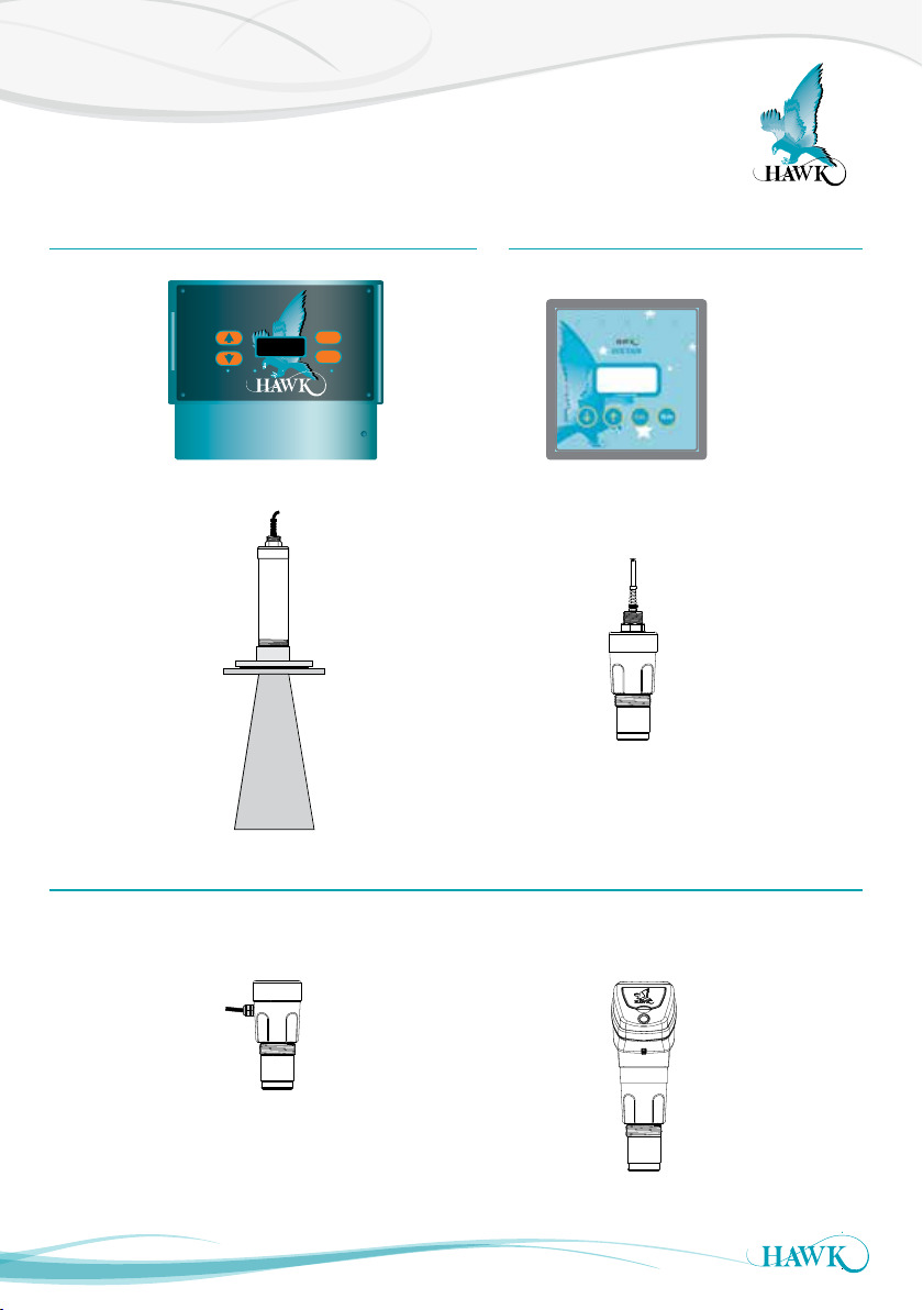
Remote Amplier Panel Mount Remote Amplier
SULTAN 234
RELAY 1 RELAY 2
10kHz Remote
Transducer
Cone
50kHz SMART Unit
CAL
RUN
RELAY 3
RELAY 4 RELAY 5
40kHz Remote
Transducer
Flange
Remote systems consist of an amplif ier and separate transducer
of varying size & shape depending on frequency
30kHz Integral Unit
SMART & Integral units combine both the amplifier and
transducer functions in a single housing
3
Page 4
Flange and Cone Assembly
Sultan Acoustic Wave Series
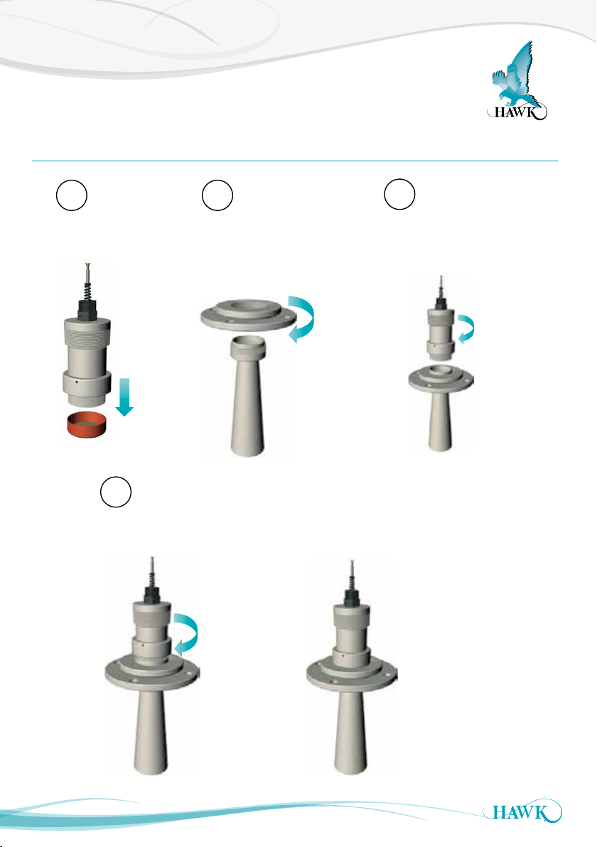
AWR234 Remote Amplier
1
Remove red cap
(including cardboard).
Note! Direction of
flange, smallest ring
this way up
4
Tighten the locking ring down to
the flange to fix the
components in place.
2
Screw the flange assembly fully
down onto the cone (as far
down as it will go until the parts
are tightly fastened).
↑
COMPLETE ASSEMBLY
(appearance above flange may differ for
integral and smart units).
3
Screw the transducer tightly
down onto the flange and cone
assembly.
User mountings should only
connect to the larger (lower)
isolated mounting flange.
No other part of the sensor
assembly should touch any
other structure or object.
4
Page 5
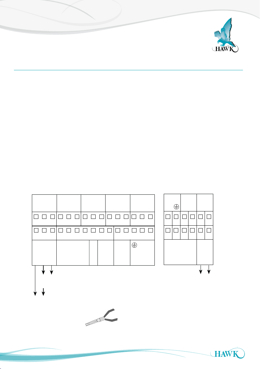
Wiring The Unit
Sourcing 4-20mA from Sultan
Sultan Acoustic Wave Series
Sultan Remote Units
The Sultan Remote amplier has wiring information printed inside the ip lid of the unit.
Unscrew the lower flip lid to access the wiring
terminals.
Ensure your power source is deactivated before
handling power wires.
Pass cables through the cable entry gland before
wiring into the terminal block.
To connect a wire, remove the required terminal
block with pliers place the wire in firmly screw down
the connection. The transducer terminals are labeled
by colour on the PCB.
234 wire version 2 wire version
RELAY 1
NC
16 17 18 19 20 21 22 23 24 25 26 27 28 29 30
1 2 3 4 5 6 7 8 9 10 11 12 13 14 15
Is
+
RELAY 2
NC
COM
NO
–
RED
TRANSDUCER DC-In AC- In*4-20mA
RELAY 3
NC
COM
NO
BLUE
WHITE
BLAC K
COM
Test In
COMMS
NO
B
RELAY 4
NC
COM
–
A
If you are connecting HawkLink communications,
connect the blue wire to B and the white wire to A.
The black wire can be connected to the DC- or GND
terminal next to A.
Tighten cable entr y gland(s) and cover to ensure
sealing is effective.
RELAY 5
NO
NC
COM
NO
+
1L
N
COMMS
B
A
Test In
7 8 9 10 11 12
1 2 3 4 5 6
RED
BLAC K
TRANSDUCER
+
BLUE
WHITE
4-20mA
Shld
Shld
–
Sinking 4-20mA
from user device
OR
5
*AC-In is r eplaced b y 36- 60VDC wit h
Power Inpu t Option ‘C ’.
Use long nose pliers to extract terminals
Sinking 4-20mA
from user device
Page 6
Wiring The Unit
Sultan Acoustic Wave Series
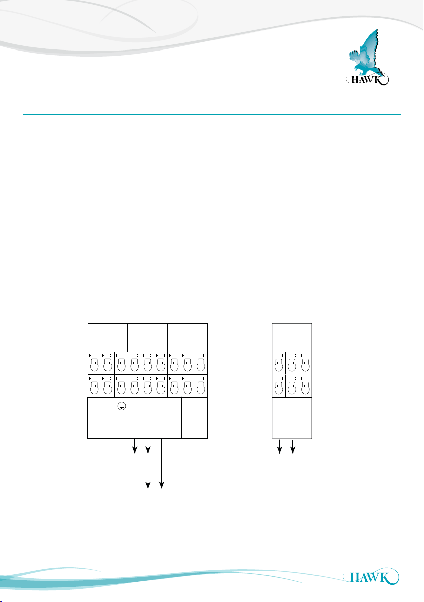
Sultan Integral Units
The Sultan Integral unit has wiring information printed inside the ip lid of the unit.
Unscrew the lid to expose the facia.
The lid can be snapped back to allow easier access
for wiring. When finished, first re-snap the double
hinge into position before closing the lid. The top half
of the facia is a flip cover which exposes the wiring
terminals.
Ensure your power source is deactivated before
handling power wires.
Pass cables through the cable entry gland before
wiring into the terminal block.
234 wire version
RELAY 1
NC
COM
1L
N
AC-In
NO
COMMS
A
–
4-20mA
+
RELAY 2
NC
B
COM
Shld
Is
–
Test In
DC-In
To connect a wire, push down on the button above
the terminal with a small flat head screwdriver and
place the wire in the terminal. Release the pressure
on the button to close the terminal and then pull on
the wire to check that it is secure.
If you are connecting HawkLink communications,
connect the blue wire to B and the white wire to A.
The black wire should be connected to the Shld
terminal.
Tighten cable entr y gland(s) and cover to ensure
sealing is effective.
2 wire version
COMMS
NO
+
A
+
–
4-20mA
B
Shld
Test In
Sinking 4-20mA
from user device
OR
Sourcing 4-20mA
from Sultan
Ensure that any unused cable gland entries are plugged or sealed.
6
Sinking 4-20mA
from user device
Page 7

Wiring The Unit
Sultan Acoustic Wave Series
Sultan Panel Mount Units
The Sultan Panel Mount has wiring information printed on the back of the unit.
Terminal blocks can be removed during installation
to allow easier wire connection. Take care to return
them to the correct position.
Ensure your power source is deactivated before
handling power wires.
Ensure terminals are open by screwing counter
clock wise with a flat head screwdriver. Place the
exposed wires into the open terminals and tighten
until firm.
234 wire version 2 wire version
RELAY 1
NC
N
RELAY 2
NC
COM
NO
1L
+
–
COM
COMMS
RELAY 3
NC
COM
NO
A
B
Test In
TRANSDUCERDC-InAC-In 4-20mA
NO
RED
RELAY 4
NC
COM
BLUE
BLACK
NO
WHITE
RELAY 5
NC
COM
–
+
The transducer terminals are labeled by colour on the
back panel.
If you are connecting HawkLink communications,
connect the blue wire to B and the white wire to A.
The black wire can be connected to the DC- or GND
terminal next to A.
NO
N/C
N/C
N/C
N/C
–
COMMS
A
B
Test In
RED
BLACK
TRANSDUCER
Is
+
–
BLUE
WHITE
4-20mA
Sinking 4-20mA
from user device
N/C
Sinking 4-20mA
from user device
OR
Sourcing 4-20mA
from Sultan
7
Page 8
Wiring The Unit
COMMS DC-IN
A
B
12-30VDC
+
RS 485
AC-IN
N
L1
80-265VAC
COM
NO
RELAY 2
NC
COM
NO
Test In
Is
N
+
–
Driving 4-20mA from
Sultan to user PLC
Modulating
4-20mA from
PLC input
Sultan Acoustic Wave Series
Sultan SMART Units
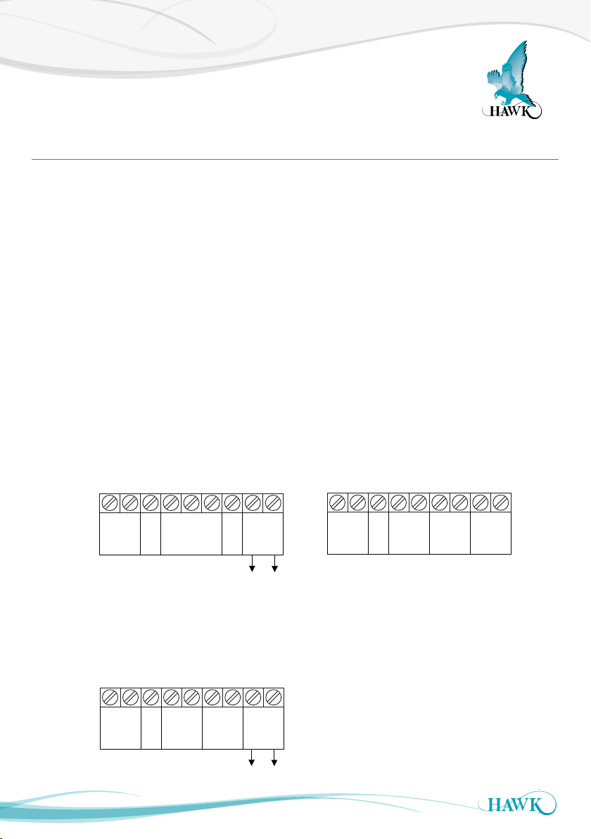
The Sultan SMART unit has wiring information printed inside the lid of the unit.
Screw Cap Version
Unscrew the lid to expose the terminals. It is
recommended you remove the terminal block from
the unit before wiring - to do this, insert a screw driver
into one of the middle terminals to lever the block out.
Pass the cables through the cable entry gland before
wiring in to the terminal block.
Ensure the terminal is open by screwing counter
clock wise with a flat head screwdriver. Place the
exposed wires into the open terminals and tighten
until firm. Inser t the block back into the unit when
wiring is complete. Press firmly on the plug in terminal
block to ensure it is fully home.
AWSTA version AWSTC version
PURPLE
WHITE
BLUE
BLACK
A
B
–
Test In
COMMS
GREEN
YELLOW
+
–
4-20mA
Sinking 4-20mA
from user device
(loop powered)
If you are connecting HawkLink communications,
connect the blue wire to B and the white wire to A.
The black wire can be connected to the DC- terminal
next to B.
Tighten cable entr y gland(s) and cover to ensure
sealing is effective.
IP68 Sealed Cable Version
Connect the free ends of the cable following the wire
colours as shown in the terminal diagrams.
BROWN
ORANGE
PURPLE
WHITE
BLUE
BLACK
RED
A
B
+
COM
RELAY
N / O
Test In
COMMS
–
DC in
AWSTD version
BROWN
ORANGE
PURPLE
WHITE
BLUE
BLACK
RED
GREEN
YELLOW
A
B
+
COM
–
N / O
Test In
RELAY
8
COMMS
DC in
+
–
4-20mA
Sinking 4-20mA
from user device
Page 9
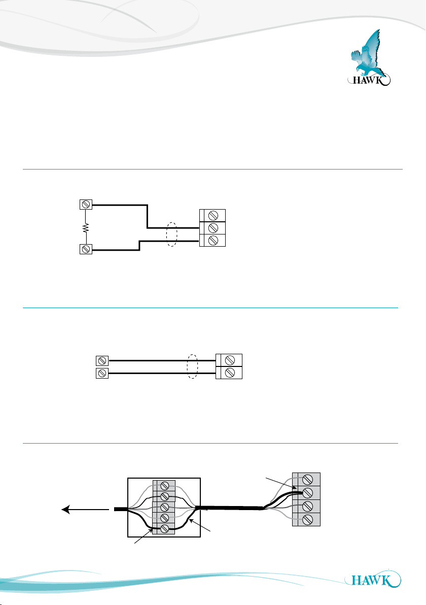
Wiring 4-20mA Output
Sultan output is
sourcing current
and provides
voltage to drive a
passive load, PLC
input, indicator or
other user device
Sultan output is
sinking current.
Voltage to drive
current loop must
be provided by
PLC, indicator,
other user device or
SULTAN
Sultan Acoustic Wave Series
When connecting the 4-20mA output to a user device such as a PLC input, DCS or indicator,
use a voltmeter to check the eld wires to be used for the 4-20mA signal. If DC voltage around
24V is present, use sinking connection. If no voltage is present, use sourcing connection.
SOURCING Type Output
Sultan output is sourcing current and provides voltage to drive a passive load, PLC input, indicator or other
user device.
–
Voltage free
user device
RL Max 270Ω
+
4-20mA
Use
shielded
cable
SINKING Type Output (also 2 wire loop powered)
NOTE:
–
Isolated current output can be made
+
common with +DC or GND if required.
4-20mA
Is
(e.g. RL – connected to GND)
Sultan output is sinking current. Voltage to drive current loop must be provided by PLC, indicator, other user
device or external DC supply.
User device
including
+24VDC source
–
+
NOTE:
–
RL Max = 750Ω if user DC Supply
+
24V.
4-20mA
Use
shielded
cable
Junction Box / Transducer Cable Extension
Re-connect
Cable Shield
to Black
Cable
Shield
To Transducer
Seperate cable
JUNCTION BOX
RED
BLACK
BLUE
WHITE
SHIELD
shielding from black
wire at junction box
9
AMPLIFIER
RED
BLACK
BLUE
WHITE
Page 10
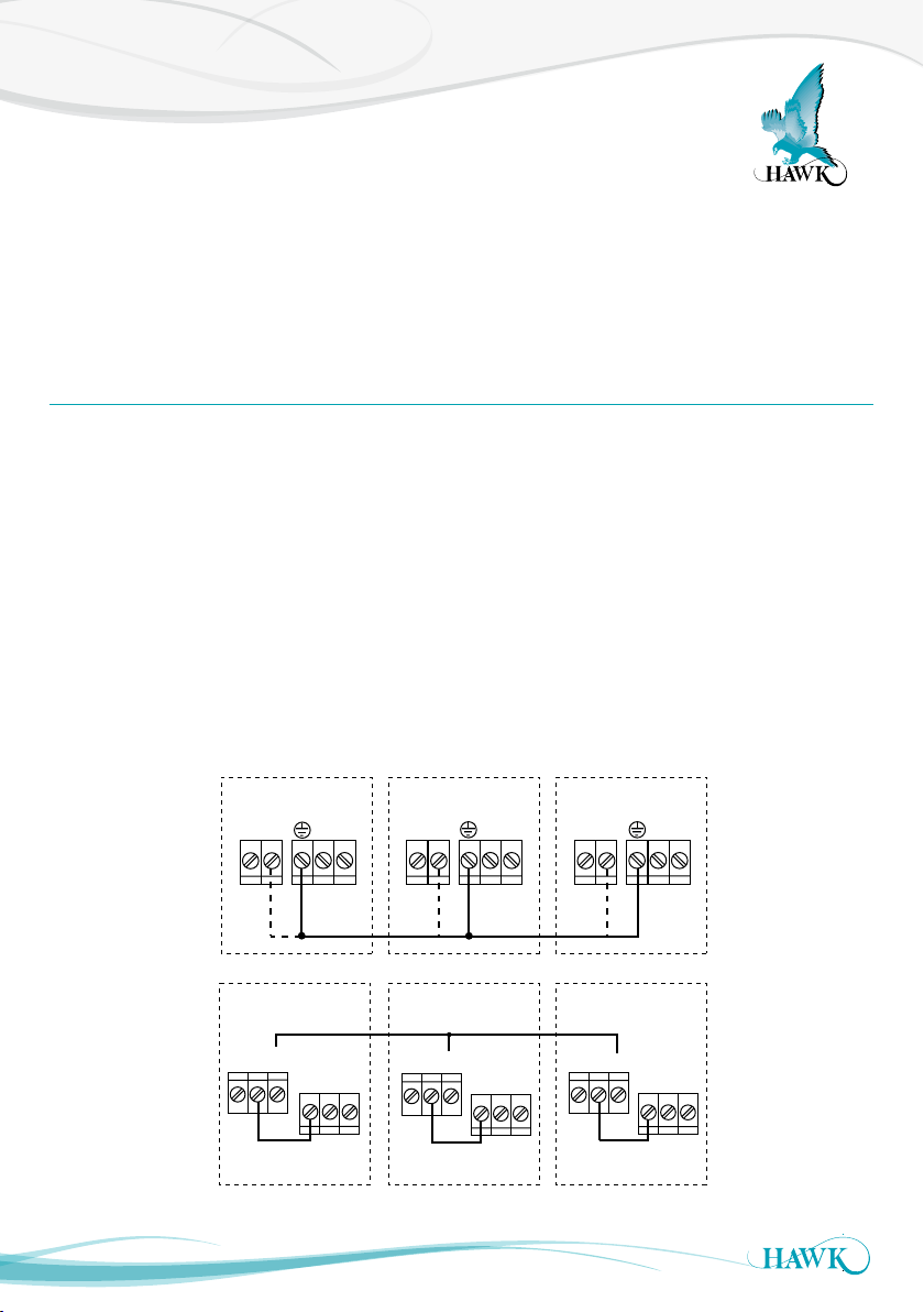
Wiring Transducer for Anti Crosstalk
Sultan Acoustic Wave Series
The term crosstalk is used to refer to inter ference between acoustic wave units of the same frequency
located near one another. The units can ‘hear’ direct or reflected signals from one another. This can cause
randomly false measurements and outputs whilst giving correct performance at other times.
Crosstalk is more likely to exist when there are multiple units in a small enclosed area with highly reflective
surfaces and with fast moving applic ations.
Wiring for Anti Crosstalk
1. Link all units to a common ground, or parallel connect their ‘GND’ or ‘DC-’ terminals.
*GND and DC- terminals are electrically connected inside Sultan 234 units, so either one may be used.
2. At each individual unit, wire a connection bet ween a Relay (eg Relay 1) ‘Common’ terminal and the
‘TEST’ terminal of the same amplifier.
3. Wire a connection between the chosen Relay ‘Normally Open’ terminals of all units to be linked
(parallel connection of all units).
4. In the Output Adjust menu for each unit program the chosen Relay to ‘FS’ (Fail-safe) mode).
The units will now be linked so that they cannot crosstalk.
5. (UPDATE MARCH 2012). New release software includes an additional menu in the ‘Output Adjust’ section
called ‘ test input’. The option ‘Synchronise’ improves the cross talk sequencing for larger amounts of units.
HAWK does not recommend more than 6 transducers in a single anti cross talk circuit.
1.
2.
3.
SULTAN 1
AC INDC IN
+
N
-
L1
SULTAN 1 SULTAN 2 SULTAN 3
RELAY1
COM
NO
NC
COMMS
A
B
Test In
SULTAN 2 SULTAN 3
AC INDC IN
COM
N
-
L1
NO
COMMS
B
Test In
+
RELAY1 RELAY1
NC
+
-
NC
COM
A
AC INDC IN
N
L1
NO
COMMS
A
B
Test In
10
Page 11
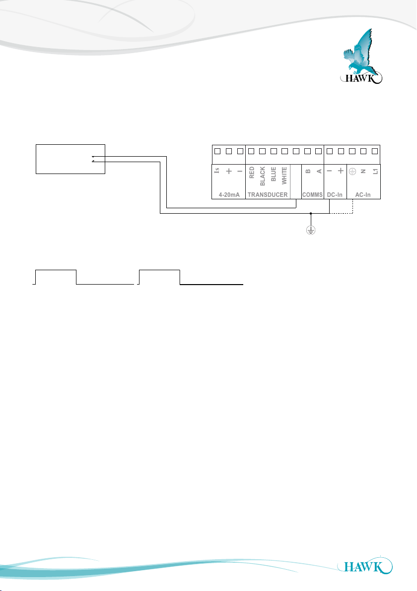
Digital Output Pulse Sequencing
Sequencing Sultan Pulse Rate via Digital Controller
321 5
C
D
4 876
A
B
+
–
1L
+
–
N
RED
BLACK
BLUE
WHITE
Is
TRANSDUCER
DC-In
AC-I n
4-20mA
COMMS
Sultan Acoustic Wave Series
A PLC/DCS with digital outputs can be used to control or sequence pulse rates.
Sultan Terminal RailPLC / DCS
Digital Output
Sequence Timing
Relay On
PLC / DCS
Min 120mS
Running Minimum Time
250mS + M x 6mS
1 2 3 4 5 6 7 8 9 10 11 12 13 14 15
Relay On
PLC / DCS
~
Min 120mS
Running Minimum Time
250mS + M x 6mS
Test In
11
Page 12
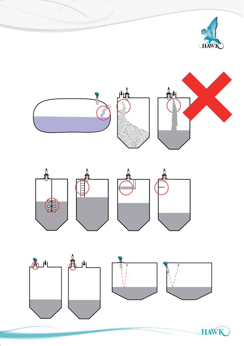
Incorrect Mounting
Sultan Acoustic Wave Series
These are examples of common INCORRECT mountings which can prevent the unit from
operating correctly.
Do NOT mount near infeed
Do NOT mount over or adjacent to any obstacles
Do NOT mount cone or transducer
face above roofline
12
Do NOT mount on angle
in liquid applications
Page 13
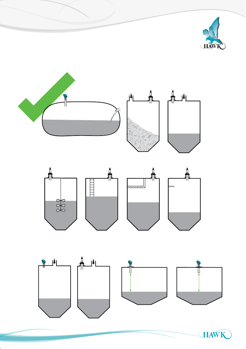
Correct Mounting
Sultan Acoustic Wave Series
Mount away from infeed
Mount away from all obstacles
Mount cone / transducer
face within the vessel
13
Mount perpendicular
to liquids
Page 14

Installation Guide
Sultan Acoustic Wave Series
Amplier
Select a suitable mounting position that is protected
from direct sunlight. If necessar y, utilize a sun
hood (HAWK supplies purpose made sun hoods).
Observe the minimum and maximum temperature
limits (-20°C/-4°F to 60°C/140°F) Do not mount near
sources of electrical noise such as high current
cables, motor starters, or variable speed drives. Avoid
mounting in high vibration areas such as handrails
and rotating plant. Use rubber absorption mounts if
mounting in light vibration areas. Protect the PCB
assembly before knocking out the cable and conduit
entry holes.
Panel Mount
• Select a suitable position within a panel layout which
allows clearance around the outside of the front
panel of the unit and also behind the panel for
clearance around the screw fixing clamps used to
retain the unit.
• Ensure that sufficient space is available behind
the panel to accommodate the depth of the amplifier
housing, and also allow cable bend clearance for
wiring to the terminals on the rear of the amplifier.
• Mark and cut a 90x90mm (3.54x3.54”) square cut
out through the panel in the desired position.
• Insert the Sultan amplifier through the panel and
install supplied screw clamps into the slotted holes
in the amplifier housing.
• Tighten the screws until just firm to secure the
amplifier in place.
• Connect wiring as required to the correct terminals
on the removable rear panel connectors. When
plugging connectors in to the rear panel, ensure that
they are re-installed in the correct position.
Transducer
Selecting a suitable position to mount the transducer
on the vessel is the single MOST IMPORTANT step.
Please read all of the installation guide and contact
your HAWK representative if you have any doubts or
questions. The transducer face MUST be at least the
blanking distance away from highest product level in
the vessel.
Use common sense when selecting the transducer
mounting position. A clear line of sight from the
transducer to the product being monitored is
required.
Take into account the change in material shape and
level. The acoustic pulse must reflect back to the
transducer.
Incorrect Mounting
Failure to mount the unit suitably can result in
incorrect measurement and may cause process
issues such as overfilling or damage to critical
components.
Process Conditions
Ensure the process conditions within the vessel such
as temperature, pressure and chemical composition
of contents are within the specifications Sultan unit.
The unit should not normally come into contact with
the measured content.
14
Page 15
Installation Guide
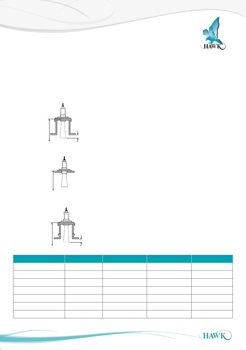
Nozzle mount
Sultan Acoustic Wave Series
Minimum Insertion
The transducer face or cone must be at least 50mm
(2 inches) inside the tank.
If the transducer needs to be mounted above the roof
line, use an appropriate standpipe or nozzle.
Blanking
Minimum
50mm (2")
Flush mount
Blanking
Stand pipe mount
Moisture Seal
Sultan Integral and Smart units have cable glands
with a moisture seal which must be tightened around
the cable. Any unused glands must be plugged and
sealed.
Transducer Location
It is vital that the Transducer has a clear view of the
product surface at all times and is kept away from
the inflow to avoid interference.
Blanking Distance
The unit will ignore any echoes and will never
measure within its Blanking distance.
Minimum values must be respected. Where possible
use the conservative values and increase this
distance by 50% if there is foam, dust, steam, or
condensation in the vessel being monitored.
(Refer to Blanking Distance table.)
If using a flange mounting, use a rubber or neoprene
gasket and washers. If using a nipple mounting,
ensure that the mounting bracket is >6mm (0. 24 in)
from the rear of the transducer. Do not over tighten
the lock nuts.
Minimum
Blanking
50mm (2")
Blanking Distance Minimum Nominal Conservative
Transducer Frequency
AWRT50 50kHz 0. 25m (10 ”) 0.3m (1ft) 0.35 m (1.2f t)
AW RT40 40kHz 0 .3 m (1.1ft) 0.35 m (1.2f t) 0.4m (1.4ft)
AWRT30 40kHz 0.35m (1.5ft) 0. 4m (1f t) 0.5m (2.2ft)
AWRT20 20kHz 0.5 m (2.2ft) 0. 6m (1. 3f t) 0.8m (2.6ft)
AWRT10 10kHz 1.0m (3.3ft) 1.1m (3.5ft) 1.3m (4.2ft)
AWRT5 5kHz 1.2m (3.9ft) 1.4m (4. 6f t) 1.5m (5f t)
Always use conservative nominated distances if possible.
15
Page 16
Installation Examples
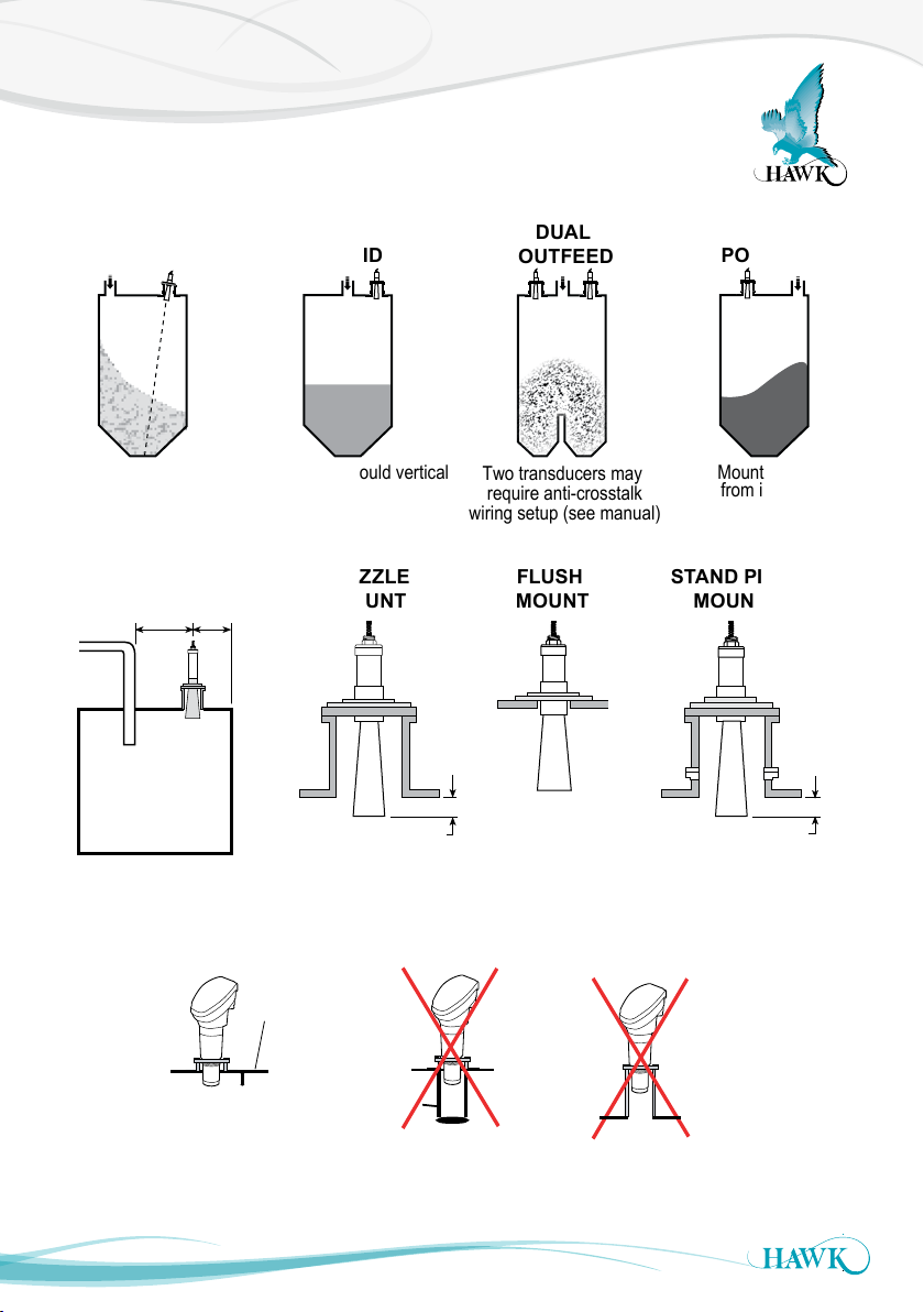
2" VERSION
min 20mm
inside tank
Intrusive
pipe
Correct
Incorrect
Vessel
roof
Threaded mounting should only be
used where a flange/cone mounting
is impossible.
Hawk recommends & supplies
focaliser cones for all transducers.
Incorrect
Face must not be
inside mounting
Sultan Acoustic Wave Series
SOLID
(Granular)
Aim transducer at
point of outfeed.
MOUNTING
POSITION
2/3
1/3
Infed
Pipe
Vessel
LIQUID
Transducer should vertical
NOZZLE
MOUNT
Minimum
50mm
DUAL
OUTFEED
Two transducers may
require anti-crosstalk
wiring setup (see manual)
FLUSH
STAND PIPE
MOUNT
POWDER
Mount away
from infeed
MOUNT
Minimum
50mm
16
Page 17
Setting Your System
Relay Level 2
Sultan Acoustic Wave Series
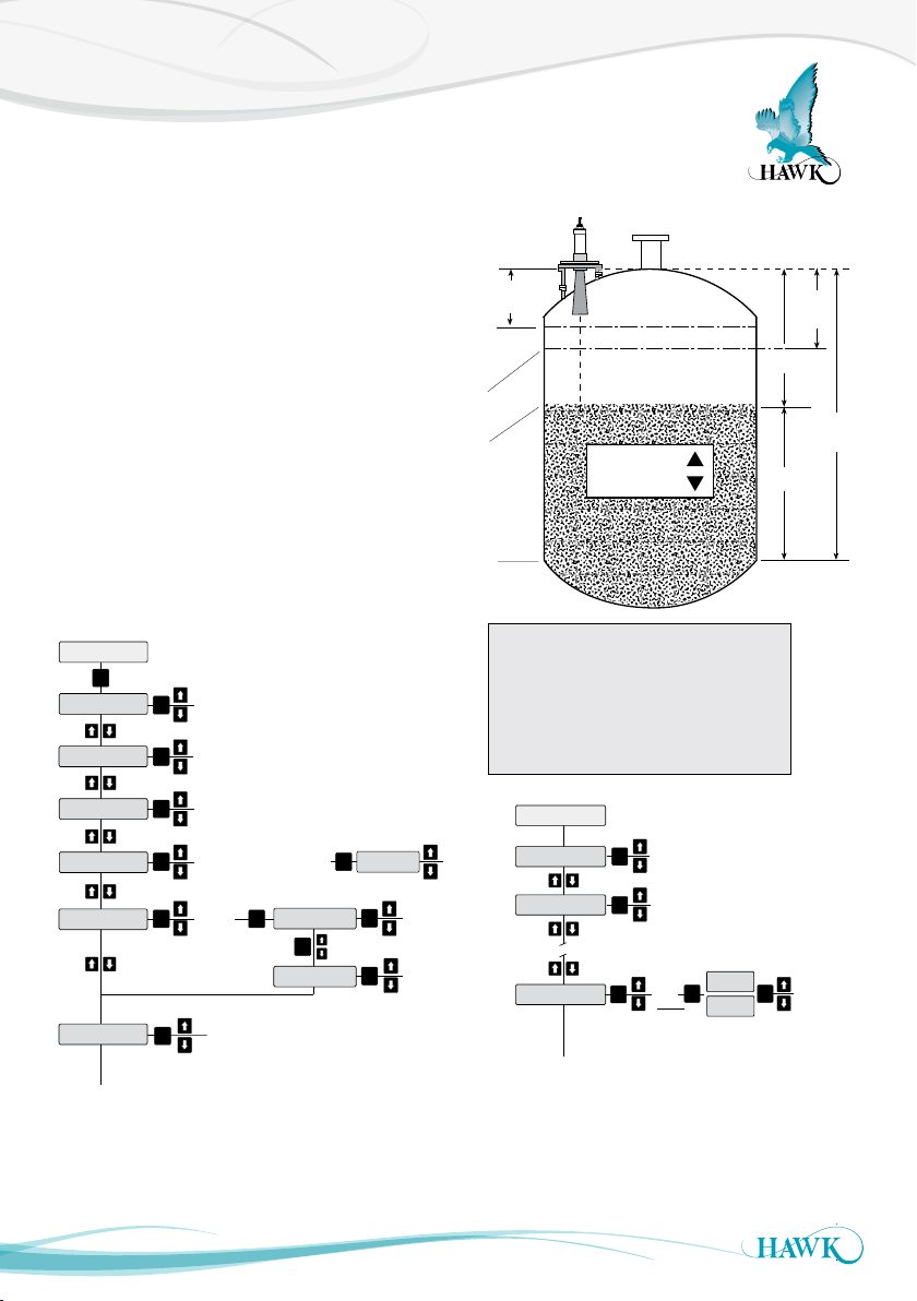
After the unit has been installed, mounted and
powered you can now enter the Quickstart settings to
get the unit operational in your application conditions.
Be sure to enter settings for High & Low level, App
Type, Fill Rate and Empty Rate of your vessel.
If you are unsure of your specific fill & empty speed
enter a value you are sure is faster than your process.
All of the mentioned settings (except Blanking) are
in the ‘Quickset’ menu of the unit. You access
this menu on the control pad by pressing CAL and
entering Unlock code 0.
You may also need to set relay switch points. These
are found in ‘Output Adjustment’. Relay alarms can
be set on/of f for hi/lo levels and failsafe.
(A)
(B)
(C)
(D)
(E)
Blanking
zone
Fill Rate
Empty Rate
Space
Material
High
Level
Low
Level
QuickSet
CAL
Unit
Low Level
High Level
Fail Safe
App Type
Display Mode
17
Select FailSafe
mA output
CAL
Fill Rate
Empty Rate
Material%
Flow
Volum e
Flow Tbl
Feet
Metres
Centimeters
Inches
CAL
Select unit of
CAL
measurement from
Adjust vessel l ow level (maximum me asured
CAL
distance from transducer face)
Adjust vessel h igh Level (minimum
CAL
measured dis tance from t ransducer f ace)
3.50mA
3.80mA
CAL CAL
20.20mA
Last Known
Position
Slurry
CAL
Solids
Liquids
Note: If using G osHawk PC
comms you mus t change fill
& empty rate A FTER selecting
app type.
Avg Matrl
Diff O/P
CAL
Space
Material
Fail Time
CAL
CAL
Adjust
vessel
fill rate
Adjust
vessel
empty rate
(A) Transducer Face - Top of Flange
(B) End of Blanking Zone
(C) High Level or 100% (20mA) position.
(D) Product Level being measured
(E) Low Level or 0% (4mA) position.
High Level = Distance A to C
Low Level = Distance A to E
Output Adj
Filling damping.
Number of pulses
CAL
averaged for output
Adjust Empty Damping
CAL
CAL
Relay Triggers - Denergise,
Energise, Fail Safe, O ff
Adjust
Fail time
(seconds)
Fill Damp
Empty Damp
Rly Mode 1
Rly Modes 2-5
DEN
EN
FS
OFF
RlyL1
CAL
RlyL2
Set Relay
Level 1 &
CAL
Example EN
L1 = relay OFF point
L2 = relay ON point
Example DEN
L1 = relay ON point
L2 = relay OFF point
Page 18
Dimensions
Sultan Acoustic Wave Series
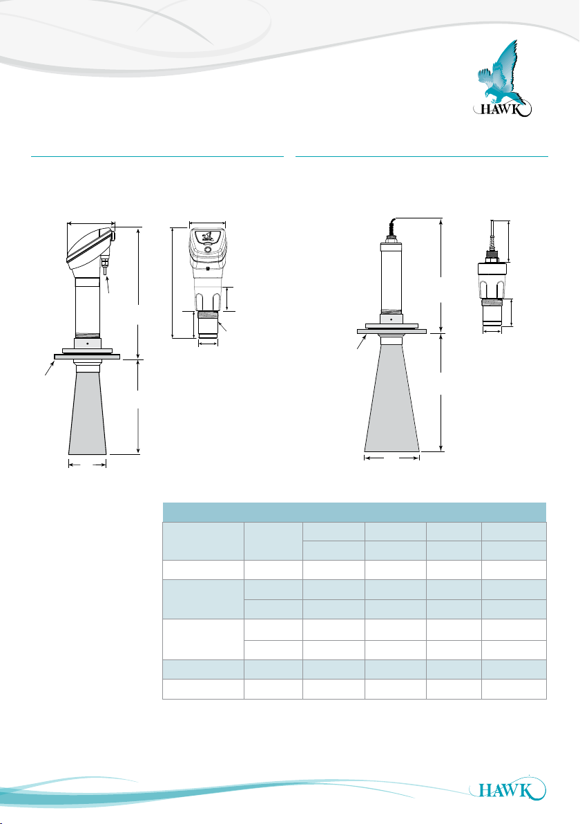
Integral Units Remote Transducers
Standard Type Compact Type
(2”BSP / NPT)
110mm (4.3”)
305mm (12”)
(3.1”)
80mm
53.5mm
(2.1")
75mm
2" BSP or
NPT THD
See
Flange
Table
160mm (6.3”)
3 x M16
Conduit
entries
C
B
A
All cones must protrude
into the main volume of
the vessel by at least 50
mm (2 inches) past the
lower end of the mounting
nozzle.
Sensor
Frequency
5 kHz 10” 236 10.0 455 17.9 8 4 0 33.1 750 29.5
10 kHz
15 kHz
20 / 30 kHz 4” 98.5 4.0 280 11.0 390 15.4 300 11.8
30 / 40 / 50 kHz 4” 98.5 4.0 280 11.0 350 3.8 260 10. 2
Standard Type
Compact Type
(2”BSP / NPT)
1" BSP/NPT
Nipple
(2.9”)
See
Flange
Table
D
53.5mm
B
A
Cone / Transducer Dimensions Table
Selected
Flange
10” 236 10.0 4 5 5 17. 9 540 21.3 4 5 0 17. 7
8” 195 8.0 2 8 0 11.1 540 21.3 45 0 17. 7
10” 236 10.0 4 5 5 17. 9 440 17.3 350 13.8
8” 195 8.0 280 11.0 440 17.3 3 50 13. 8
A B C D
mm in. mm in. mm in. mm in.
(2.1")
~80mm (3.1”)
(3.1”)
80mm
18
Page 19
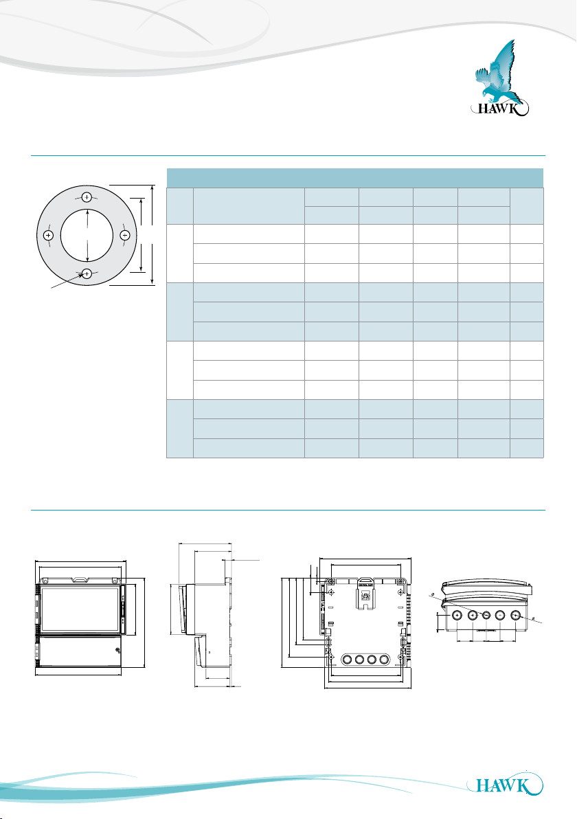
Dimensions
Note: Other flang e sizes available upon reque st.
STANDARD ANSI/DIN/JIS FLANGE DIMENSIONS
FLANGE
TYPE
E (PCD) F (OD) G (ID) H (Hole)
mm in. mm in. mm in. mm in.
FA4
ANSI class 150
190.5 7.5 229 9.0 100 4 19 0.75
FD4
DIN100 PN10/16
180 7.1 220 8.7 100 4 18 0.71
FJ4
JIS B2220-1984 10kg
175 6.9 210 8.4 100 4 19 0.75
FA8
ANSI class 150
298.5 11.8 343 13.5 200 8 22 0.85
FD8
DIN200 PN10
295 11.6 340 13.4 200 8 22 0.85
FJ8
JIS B2220-1984 10kg
290 11.4 330 13.0 200 8 19 0.91
FA10
ANSI class 150
362 14.3 406 16.0 250 10 25 1.02
FD10
DIN250 PN10
350 13.7 395 16.0 250 10 23 0.85
FJ10
JIS B2220-1984 10kg
355 14.0 400 15.7 250 10 25 0.99
SIZE
4”
8”
10”
6”
FA6
ANSI class 150
FD6
DIN150 PN10
FJ6
JIS B2220-1984 10kg
241.5 9.5
240 9.4
240 9.4
279 11.0
285 11.2
280 11.0
150 6
150 6
150 6
22 0.87
23 0.91
23 0.91
No.
Holes
8
8
8
8
8
8
8
8
12
12
12
12
Sultan Acoustic Wave Series
Flanges
Size Flange Type
H
G
FLANGE TYPE:
A = ANSI Flange
J = JIS Flange
D = DIN Flange
E F
10”
Standard ANSI/DN/JIS Flange Dimensions
E (PCD) F (OD) G (ID) H (Hole)
mm in. mm in. mm in. mm in.
FA4 ANSI class 150
4”
FD4 DIN100 PN10/16 18 0 7.1 220 8.7 100 4 18 0 .71 8
FJ4 JIS B2220-1984 10kg 175 6.9 210 8.4 100 4 19 0.75 8
FA6 ANSI class 150 241.5 9.5 27 9 11.0 150 6 22 0.87 8
6”
FD6 D IN150 PN10 240 9.4 2 85 11. 2 150 6 23 0.91 8
FJ6 JIS B2220-1984 10kg 240 9.4 2 80 11. 0 150 6 23 0.91 8
FA8 ANSI class 150 29 8.5 11. 8 343 13 .5 200 8 22 0.85 8
8”
FD8 DIN200 PN10 295 11.6 340 13.4 200 8 22 0.85 8
FJ8 JIS B2220-1984 10kg 29 0 11.4 330 13.0 20 0 8 19 0.91 12
FA10 ANSI class 150 362 14.3 406 16.0 250 10 2 5 1.02 12
FD10 DIN200 PN10 350 13.7 395 16.0 250 10 23 0.85 12
FJ10 JIS B2220-1984 10kg 35 5 14.0 400 15.7 250 10 25 0.99 12
190.5 7.5 229 9.0 100 4 19 0.75 8
No.
Holes
Remote Amplier
192.5 mm (7.6”)
174 mm (6.9”)
182.5 mm (7.2”)
19
111.5 mm (4.4”)
78 mm (3.1”)
14 mm (0.6”)
108 mm (4.3”)
107 mm (4.2”)
190 mm (7.5”)
50 mm (2”)
74 mm (2.9”)
4 mm (0.2”)
190 mm (7.5”)
131.5 mm (5.2”)
141.5 mm (5.6”)
167.5 mm (6.6”)
7.5 mm (0.3”)
30.7 mm (1.2”)
192.5 mm (7.6”)
147 mm (5.8”)
147 mm (5.8”)
158 mm (6.2”)
182.5 mm (7.2”)
1
6
.
2
20
.
30.0
2
33.029.029.033.0
Page 20
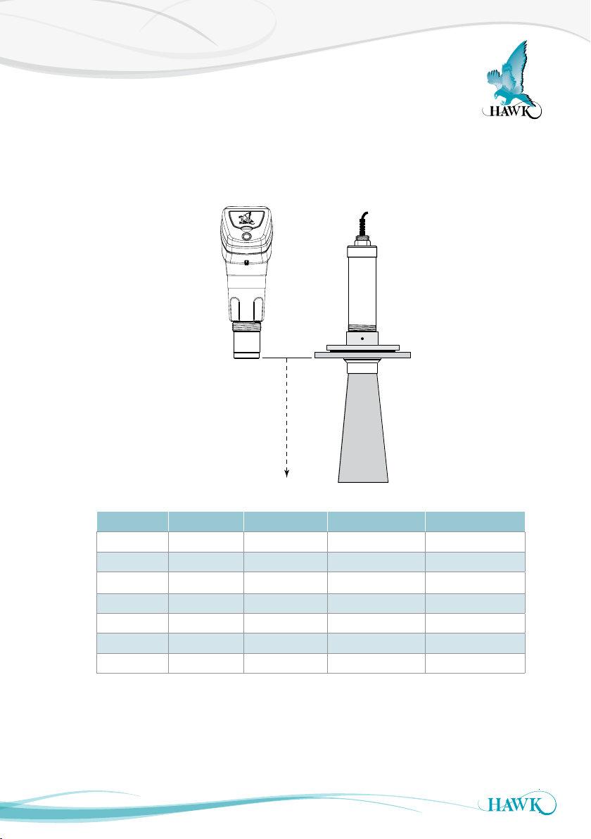
Minimum Measurement Range
Sultan Acoustic Wave Series
Each Transducer frequency has a different Blanking distance and recommended minimum distance (or high
level) between the sensor face and measured product. This distance is measured from the sensor face or the
bottom tip of flange down depending on model.
Sensor Face Flange
Part No. Frequency Minimum Nominal Conservative
AWRT5 0 50kHz 0.25m (10") 0.3m (1ft) 0.35m (1.2ft)
AW RT4 0 40kHz 0.3m (1ft) 0.35 m (1. 2 ft) 0 .4 m (1. 3ft)
AWRT30 30kHz 0.3 5m (1. 2ft) 0.4 m (1. 3f t) 0.5 m (1. 6f t)
AWRT20 20kHz 0.4 5 m (1. 5f t) 0.6m (2 ft) 0.7m (2.2f t)
AWRT15 15kHz 0.6m (2 ft) 0.7m (2. 2ft) 1.0m (3. 2f t)
AWRT10 10kHz 0.75 m (2. 5ft) 1.1m (3. 6f t) 1.3m (4.2ft)
AWRT05 5kHz 1.0m (3. 2ft) 1.5 m (4.9ft) 1.8m (5.9ft)
Always use conservative nominated distances if possible
20
Page 21
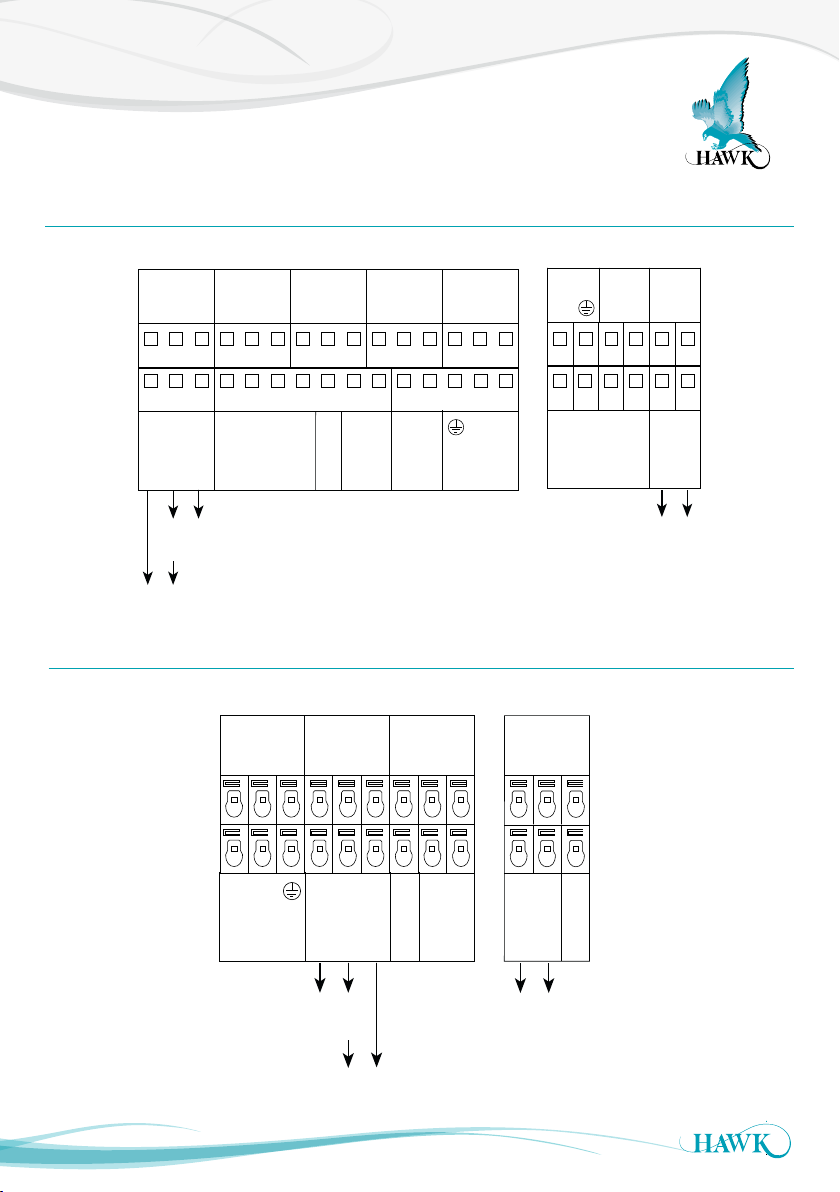
Wiring Diagrams
Sultan Acoustic Wave Series
AWR Remote Transmitter
AWR234
RELAY 1
NC
RELAY 2
NC
COM
NO
Test In
COMMS
A
B
Shld
Shld
RELAY 3
NC
COM
NO
RELAY 4
COM
NO
NC
RELAY 5
COM
NO
NC
COM
NO
16 17 18 19 20 21 22 23 24 25 26 27 28 29 30
1 2 3 4 5 6 7 8 9 10 11 12 13 14 15
Is
–
+
Sinking 4-20mA
from user device
OR
Sourcing 4-20mA from Sultan
RED
TRANSDUCER DC-In AC- In*4-20mA
AWI Integral Transmitter
AWI234 AWI2
RELAY 1
NC
1L
AC-In
7 8 9 10 11 12
1 2 3 4 5 6
+
NO
N
1L
COMMS
A
+
–
4-20mA
RED
BLUE
BLAC K
TRANSDUCER
Sinking 4-20mA
from user device
B
Shld
Test In
BLUE
BLAC K
COM
NO
N
B
WHITE
Test In
COMMS
*AC-In is r eplaced by 3 6-6 0VDC with
Power Inpu t Option ‘C’.
COMMS
A
+
–
RELAY 2
NC
B
Shld
Is
–
COM
+
–
A
Test In
4-20mA
DC-In
+
WHITE
4-20mA
–
Sinking 4-20mA
from user device
Sinking 4-20mA
from user device
OR
Sourcing 4-20mA
from Sultan
21
Page 22
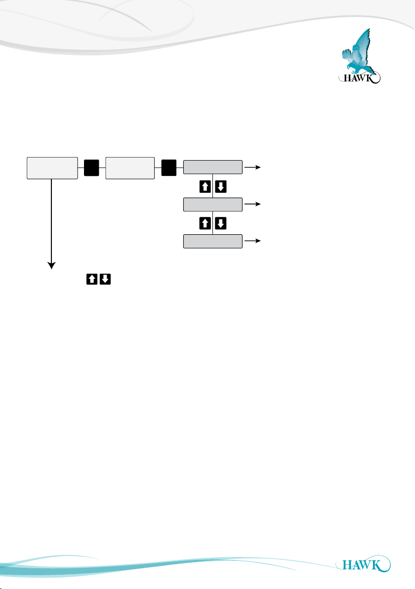
Diagnostics & Software Overview
(Diagnostics)
Sultan Acoustic Wave Series
During running mode the Sultan will always display the selected primary display mode. There are further
options referred to as ‘diagnostics’ which can be accessed using the arrow buttons which give immediate
information about unit performance.
(Primary Menus)
Space
4.124m
CAL
Unlock
0
Unlock code 0
(default) to access
primary menus
CAL
QuickSet
Output Adj
See ‘QuickSet’
See ‘Output Adjustment’
Advanced
If you press the
(displaying Space, Material% etc) the following diagnostic are shown (example values).
E: Echo
S: Size
Gn: Gain
R: Recover
N: Noise
T: Temperature
Win Fwd
Win Bk
Normal
pushbuttons while the unit is in normal operation mode
4.2
1.11V
37. 6 %
2.3%
1.9%
23.2ºC
3.6m
4.8m
Normal
Current distance the unit is detecting with each
pulse (does not include output damping values)
Echo size in volts - A high value (1.6-2V) indicates
the unit may have too much gain for the current distance
Amount of gain applied at distance echo is detected
The amount of recover gain the unit is currently
applying on top of normal gain to track the level
External noise level of similar frequency to Transducer
(eg bulk solids filling)
Temperature at sensor face
Tracking Window starting distance
Tracking Window finishing distance
Unit operational mode:
Normal operation if tracked echo is above
minimum threshold. Default minimum is 0.4V
Recover if below minimum threshold, the unit will
search for an echo for as long as the fail time
See ‘Advanced’
22
Page 23
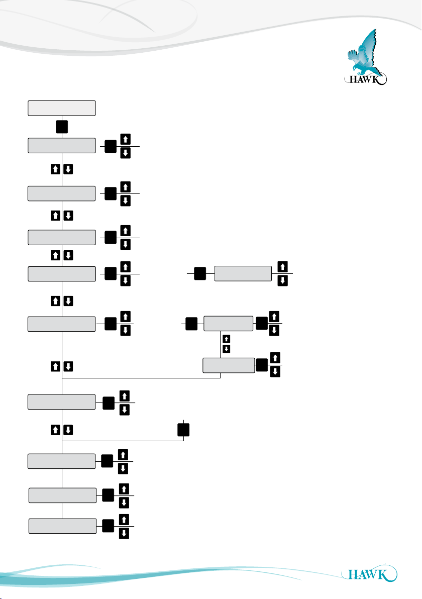
Quickset Flow Chart
Blanking
Distance
Sultan Acoustic Wave Series
QuickSet
CAL
Unit
Low Level
High Level
Fail Safe
App Type
Display Mode
Select unit of
CAL
measurement
from
Adjust vessel low level (maximum
CAL
measured distance from
transducer face)
CAL
Adjust vessel high Level (minimum
measured distance from transducer face)
3.50mA
CAL CAL
3.80mA
20.20mA
Last Known
CAL
Note: If using GosHawk PC
comms, after changing ‘app type’
you need to reset fill & empty rate
to 1 and then enter your preferred values.
CAL
See P20
App types
Avg Matrl
Diff O/P
Space
Material
CAL
*
*
CAL
Feet
Metres
Centimeters
Inches
Fill Speed
Empty Speed
Material%
Flow
*
Volume
Flow Tbl
Fail Time
CAL
CAL
See ‘Display Modes’
*
on page
Adjust Fail
time (seconds)
View or adjust fill rate
(fast/med/slow/custom)
View or adjust empty rate
(fast/med/slow/custom)
27
Oset
Amp Reset
Lock Code
23
CAL
CAL
CAL
Adjust offset value
Resets Amplifier to default settings
(quickset & output adj parameters).
Set unlock code (default 0)
Page 24

Quickset Parameters
Sultan Acoustic Wave Series
Quickset
To access to the Quickset parameter menu, press
and hold the
on the LCD. Then use the
the access code.
The factory default is 0.
button until “Unlock 0” is displayed
buttons to select
Unit
Allows the user to select the units for display of
measured distances and relay set point programming.
The choices are
metres / centimetres or feet / inches.
Low Level
Sets the distance from the face of the transducer
that corresponds to the low level in the vessel being
monitored (4mA analog output level).
High level
Sets the distance from the face of the transducer
that corresponds to the High level in the vessel being
monitored (20mA analog output level).
Note: There must be a minimum span of 100mm
between high & low levels.
Fail-Safe
Allows the user to select their preferred fail safe
condition the 4-20mA output will transmit when the
unit enters fail safe mode. There are 5 possible mA
output failure values. They are: 20mA, 4mA, Last
Known, <4.00mA and >20.00mA.
Application Type
Allows the user to select the type & speed of the
customer application to automatically program unit
settings. See dedicated ‘Application type’ on next
page.
Display Mode
Allows the user to select the primary display mode
reading. Options are average material, diff o/p, space,
material, material%, flow, volume and flow tbl. ‘Space’
is default.
Lock Code
Allows the user to set an access code other than 0 to
avoid unauthorised changes to the programming. Use
the
buttons to select the desired access code.
24
Page 25
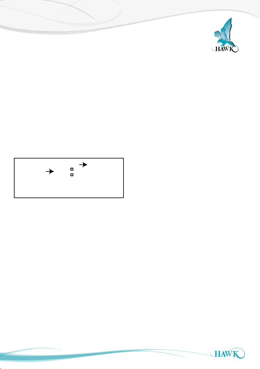
Application Types
Selected
App Type
Custom
View
Fast
Med
Slow
Fill / Empty
Rate
Sultan Acoustic Wave Series
HAWK introduced additional application types to the
Sultan series in software v5.78 (released 16 March
2012) along with a basic selection of process speed
of ‘fast ’, medium, or ‘slow’. You can also manually
select and adjust the fill & empty speeds (in selected
unit per hour eg metres per hour) by using the
‘Custom’ option.
The application types are selectable in the
‘Quickstart ’ menu. After you select the application
type the first menu you will see is ‘view’. To modify
the settings use the arrows to scroll to ‘ fast’, ‘medium’,
‘slow’ or ‘custom’. ‘View ’ displays the currently
selected speeds.
Bin Level
Fast Fill 100m/h Empty 100m/h
Med Fill 50m/h Empty 50m/h
Slow Fill 10m/h Empty 10m/h
Cement
Fast Fill 20m/h Empty 20m/h
Med Fill 10m/h Empty 10m/h
Slow Fill 5m/h Empty 5m/h
Coal
Fast Fill 100m/h Empty 100m/h
Med Fill 50m/h Empty 50m/h
Slow Fill 10m/h Empty 10m/h
Conveyor
Fast Fill 6000m/h Empty 6000m/h
Med Fill 3000m/h Empty 3000m/h
Slow Fill 1000m/h Empty 1000m/h
25
Crusher
Fast Fill 800m/h Empty 800m/h
Med Fill 200m/h Empty 200m/h
Slow Fill 20m/h Empty 20m/h
Detection
Fast Fill 6000m/h Empty 6000m/h
Med Fill 3000m/h Empty 3000m/h
Slow Fill 1000m/h Empty 1000m/h
Iron Ore
Fast Fill 100m/h Empty 100m/h
Med Fill 50m/h Empty 50m/h
Slow Fill 5m/h Empty 5m/h
Liquids
Fast Fill 200m/h Empty 200m/h
Med Fill 50m/h Empty 50m/h
Slow Fill 5m/h Empty 5m/h
Agitated Liquids
Fast Fill 200m/h Empty 200m/h
Med Fill 60m/h Empty 60m/h
Slow Fill 10m/h Empty 10m/h
Agitated Liquids
Fast Fill 200m/h Empty 200m/h
Med Fill 50m/h Empty 50m/h
Slow Fill 10m/h Empty 10m/h
Ore
Fast Fill 100m/h Empty 100m/h
Med Fill 50m/h Empty 50m/h
Slow Fill 5m/h Empty 5m/h
Plastics
Fast Fill 20m/h Empty 20m/h
Med Fill 10m/h Empty 10m/h
Slow Fill 5m/h Empty 5m/h
Page 26

Application Types
Sultan Acoustic Wave Series
Positioning
Fast Fill 4000m/h Empty 4000m/h
Med Fill 2000m/h Empty 2000m/h
Slow Fill 1000m/h Empty 1000m/h
Powder
Fast Fill 30m/h Empty 30m/h
Med Fill 15m/h Empty 15m/h
Slow Fill 5m/h Empty 5m/h
Reective
Fast Fill 20m/h Empty 20m/h
Med Fill 10m/h Empty 10m/h
Slow Fill 5m/h Empty 5m/h
ROM Bin
Fast Fill 1200m/h Empty 400m/h
Med Fill 700m/h Empty 250m/h
Slow Fill 300m/h Empty 100m/h
Silo Level
Fast Fill 100m/h Empty 100m/h
Med Fill 50m/h Empty 50m/h
Slow Fill 10m/h Empty .10m/h
Slurry
Fast Fill 100m/h Empty 100m/h
Med Fill 50m/h Empty 50m/h
Slow Fill 20m/h Empty 20m/h
Solids
Fast Fill 100m/h Empty 100m/h
Med Fill 50m/h Empty 50m/h
Slow Fill 10m/h Empty 10m/h
Stockpile
Fast Fill 200m/h Empty 200m/h
Med Fill 50m/h Empty 50m/h
Slow Fill 20m/h Empty 20m/h
Sump
Fast Fill 200m/h Empty 200m/h
Med Fill 40m/h Empty 40m/h
Slow Fill 10m/h Empty 10m/h
Process Sump
Fast Fill 100 0m/h Empty 1000m/h
Med Fill 300m/h Empty 300m/h
Slow Fill 20m/h Empty 20m/h
Tank Level
Fast Fill 200m/h Empty 200m/h
Med Fill 50m/h Empty 50m/h
Slow Fill 5m/h Empty 5m/h
26
Page 27
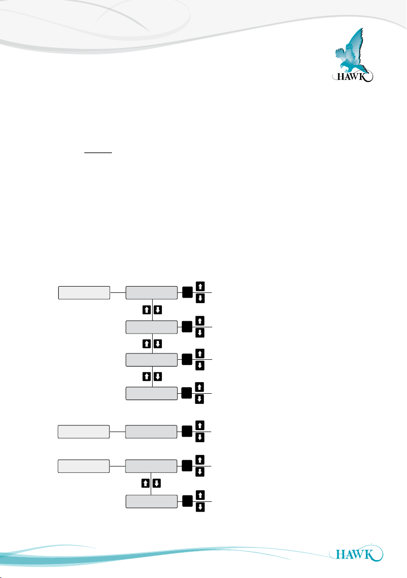
Display Mode
Sultan Acoustic Wave Series
Non-standard display modes
AvgMatrl and Dif f O/P are special operation modes which require two transducers connected to an amplifier
via a junction box. Avg Matrl calculates the average level measured by the two transducers and Diff O/P
calculates the difference in level between the two transducers. You will need to assign one transducer to ID2.
To do this connect only one of the transducers, enter ‘Quickset’ and change the display mode to AvgMatrl or
Diff O/P. Scroll down until you see 1:Sen Add 1 option, press CAL, select ‘1’ for current transducer and press
CAL again. The menu then proceeds to Tx Add:, press CAL to edit, pres UP to scroll from 1 to 2 and press
CAL to save. The currently connected transducer is now on ID2 - you can now connect the other transducer
to the junction box which will be ID1 to complete the measurement pair required for Average & Differential
measurement..
The Flow option can be used for basic open channel flow applications with a known Exponent value of
the flume/channel/weir and the known max flow rate. Low & High level need to be set to represent the
distance from the transducer face of 0-100% possible flow of the application. For more comprehensive flow
measurement please see the dedicated flow measurement unit the Sultan Flow.
liters
k liters
Flow
Flow Unit
CAL
m liters
Cube mtr
Cube ft
Flow Exp
Flow Max
CAL
CAL
Adjust to required exponent
Adjust to maximum
Flow rate value
Adjust Low cut off point
Lo Cut Off
CAL
Can be used to stop unit measuring
stagnant liqud level as flow.
AvgMatrl
Diff O/P
Sensors
LoLevel2
HiLevel2
CAL
CAL
CAL
Select number of sensors 1 or 2
Specify 2nd sensor low level
Specify 2nd sensor high level
*Press RUN twice at any time to revert to normal operation
27
Page 28

Average Level
Sultan Acoustic Wave Series
Note: Average level requires a junction box AWRT-JB-01
What is Average Level?
Average Level (AvgMatrl) is used to measure the
average of two levels using two Transducers and one
amplifier providing one output. The Transducers are
referred to as Sensor 1 and Sensor 2.
Average Material Calculation
The display mode ‘AvgMatrl’ (Average Material) gives
a result calculated as follows:
AvgMatrl = LowLevel – AvgSpace
where
AvgSpace = (Space1 + Space2 + offset)/2
Analog Output
Analog output is calculated based on the average
material level.
The span of the analog output is def ined by the
LowLevel and HiLevel parameters. The analog output
is calculated as follows:
Current (mA) = 16* AvgMatrl/ (LowLevel-Hi
Level) + 4mA
Relays
The relays are switched based on the average space
value. The relay set points L1 and L2 should be set
considering the average space values at which the
relay is required to switch.
Setting Sensor ID
You will need to assign one transducer to ID2.
To do this perform the following steps
1. Connect only one of the transducers
2. Enter ‘Quickset’ and change the display mode to
AvgMatrl
3. Scroll down until you see 1:Sen Add 1 option.
4. Press CAL to edit. Select ‘1’ for current transducer
and press CAL again.
The menu then proceeds to Tx Add:,
5. Press CAL to edit, press UP to scroll from 1 to 2
and press CAL to save.
The currently connected transducer is now on ID2
You can now connect the other transducer to the
junction box which will be ID1 to complete the
measurement pair required.
Accessing both Sensors Parameters
Both Sensor 1 and Sensor 2 parameters can be
accessed through the KeyPad.
The parameter ‘Sensor’ in ‘Advanced’ determines
which sensor (1 or 2) will be currently accessed if
required to adjust settings.
28
Page 29

Differential Level
Sultan Acoustic Wave Series
Note: Differential level requires a junction box AWRT-JB- 01
What is Differential Level?
Differential Level (Diff O/P) is the term used to def ine
the measured difference between two material levels
using two Transducers. The Transducers are referred
to as Sensor 1 and Sensor 2.
Diff Calculation
In differential Mode the material level measured
by Sensor 1 is subtracted from the material level
measured by Sensor 2. Negative results will be reset
to zero. The differential value is calculated as follow:
Diff = MaterialLevel2 – MaterialLevel1
MaterialLevel2 = LowLevel2 – Space2
MaterialLevel1 = Lowlevel1 – Space1
Analog Output
Analog output is calculated based on the differential
value.
The span of the analog output is according to
the Lowlevel1 and Hilevel1. The analog output is
calculated according the following equation:
Current (mA) = 16 * (Diff)/(LowLevel1
–HiLevel1) + 4mA
Setting Sensor ID
You will need to assign one transducer to ID2.
To do this perform the following steps
1. Connect only one of the transducers
2. Enter ‘Quickset’ and change the display mode to
AvgMatrl
3. Scroll down until you see 1:Sen Add 1 option.
4. Press CAL to edit. Select ‘1’ for current
transducer and press CAL again.
The menu then proceeds to Tx Add:,
5. Press CAL to edit, press UP to scroll from 1 to 2
and press CAL to save.
The currently connected transducer is now on ID2
You can now connect the other transducer to the
junction box which will be ID1 to complete the
measurement pair required.
Accessing both Sensors Parameters
Both Sensor 1 and Sensor 2 parameters can be
accessed through the KeyPad.
The parameter ‘Sensor’ in ‘Advanced’ determines
which sensor (1 or 2) will be currently accessed if
required to adjust settings.
Relays
Relay Mode = EN (L1 < L2) Relay Mode = DEN (L1 < L2)
OFF ON
L2 = Diff2 L2 = Diff2
L1 = Diff1 L1 = Diff1
ON OFF
29
Page 30
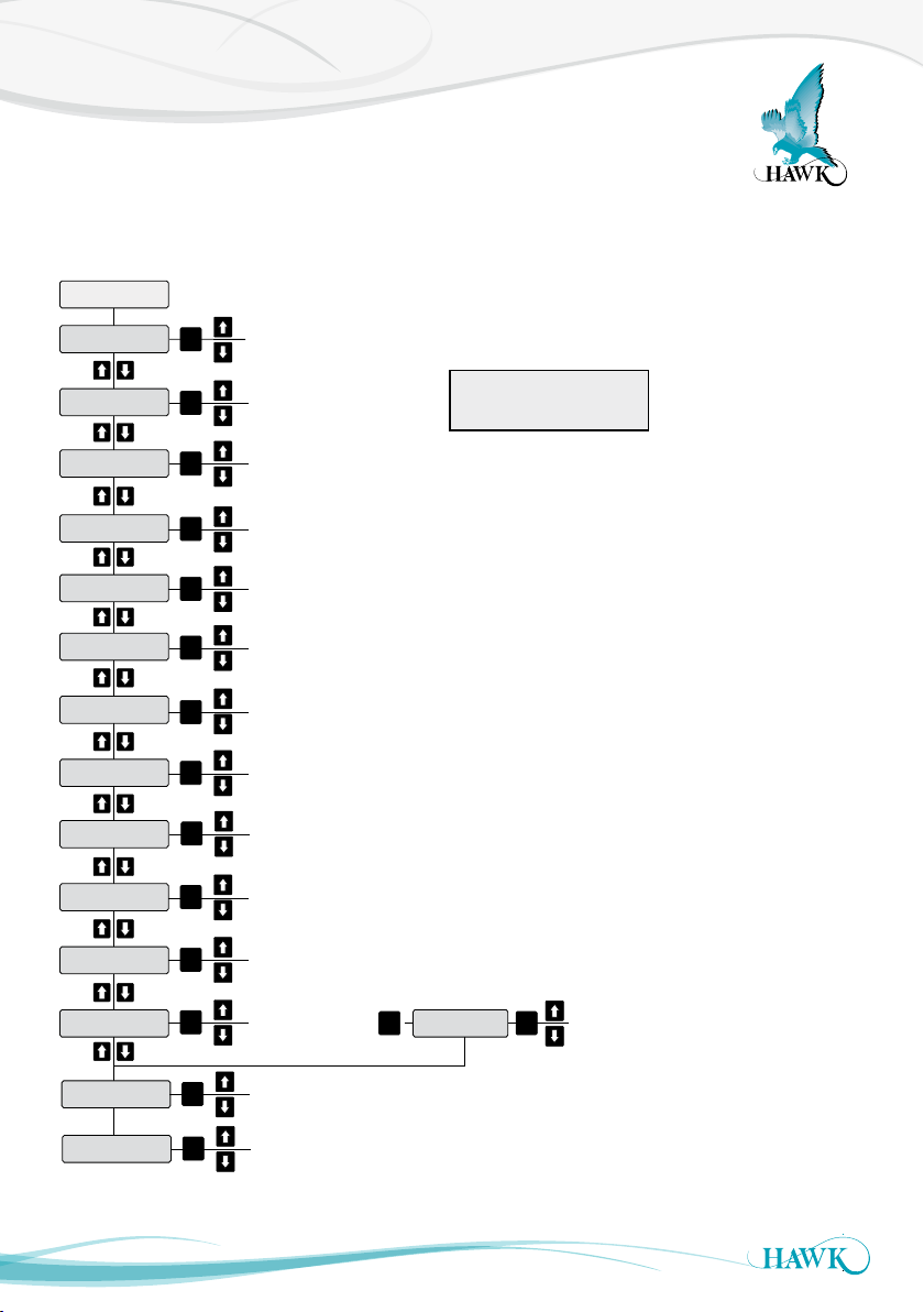
Advanced Setup Menu
Sultan Acoustic Wave Series
Advanced settings adjusts the transducer sensing characteristics. It is not recommended you adjust these
settings unless you are familiar with the effect they will have on your unit.
Advanced
Gain4
GainStep3
DistStep3
EchoSize
Threshold
Blanking
Empt Dist
Temp Trim
Dist Trim
Velocity
Map Dist
Map Used
Map Marg
CAL
CAL
CAL
CAL
CAL
CAL
CAL
CAL
CAL
CAL
CAL
CAL
CAL
Adjust transducer start gain (sensitivity to echoes)
Adjust gain step 3 %
Adjust distance of gain step 3
Unit attemps to maintain an echo strength of this value
Unit attemps to maintain an echo strength of this value
Adjust blanking from transducer face. Unit
will not track within this distance
Vessel empty distance. Unit will not track
beyond this distance
Adjust temperature trim compensation
Adjust distance trim compensation
Adjust sound velocity compensation for applications
where speed of sound is different.
Echo Mapping: Distance to be mapped from
transducer face
Echo Mapping:
On or Off
Adjust mapping margin
CAL CAL
*Press RUN twice to revert
to normal operation
Map Echo
Echo
Mapping:
Unit performs
echo mapping
routine
TX Reset
30
CAL
Restore Transducer settings to factory default
‘App type’ settings will need to be re-selected
Press CAL to pulse the unit while adjusting Tx settings.
Distance to level will be shown.
Page 31

Advanced Parameters
Sultan Acoustic Wave Series
Gain4 (Gn):
This parameter is to increase or decrease the star ting
Gain4 value (sensitivity to return echoes). Gain4 is
the primary gain control. The start point of this % is
after Gain Step 3 / Distance Step 3.
The result of changes can be seen immediately by
pressing CAL while adjusting the % (the unit will pulse
once and display distance & echo size). A ‘good’
signal size is approximately 0.8V. A signal above 2V
suggests Gain4 is too high.
Gain Step 3 / Distance Step 3 (G3 / D3):
Normally G3 and D3 are considered and adjusted as
a pair, and should only need adjustment to assist in
‘high level’ lock ups or structures close to and around
the transducer face (see troubleshooting / locking
onto high level).
The result of changes can be seen immediately by
pressing CAL while adjusting the % (the unit will pulse
once and display distance & echo size).
EchoSize
The unit uses automatic gain control to maintain
echo size to this value. While the unit is operating it
is displayed as the diagnostic S:. The default settings
for solid based applications is 0.6V and for Liquid
based applications 0.8V.
Threshold
Threshold is the minimum echo size the unit will
track. Any echo which passes this value (0.39V) the
unit will use automatic gain control to track and hold
to the EchoSize.
Blanking
The Blanking Distance is the minimum amount of
space which should be between the transducer face
and the product being monitored. This distance is a
blank zone, the unit will not track anything within this
distance.
Where possible use the conservative values and
increase this distance by 50% if there is foam, dust,
steam, or condensation.
See also ‘Minimum Measurement Range’
Empty Distance
The Empty Distance is similar to Blanking, the unit
will not track any echoes beyond this distance. Be
conser vative with this value, any empty bin with a
conical bottom may require additional distance due to
pulses ref lecting of the cone angle before returning to
the sensor face.
Digital Mapping
Digital mapping is a process where the unit scans
a vessel for all potential false echoes and applies a
filter to ignore them. Mapping should be considered
a last resort, it may interfere with the units ability to
follow the process level if not applied correctly.
Map Distance
The total distance (measured from transducer face)
the unit will map.
Map Echo
Commences mapping process.
Map Used
Select only a portion of the Map Distance to use
parameter (measured from transducer face)
Map Margin
This value is the amount of gain applied to the
mapped echoes. This value should be adjusted
in small amounts, if the value is set too high the
mapped echoes will be very large resulting in the unit
struggling to correctly following process level while it
passes the mapped area.
31
Page 32
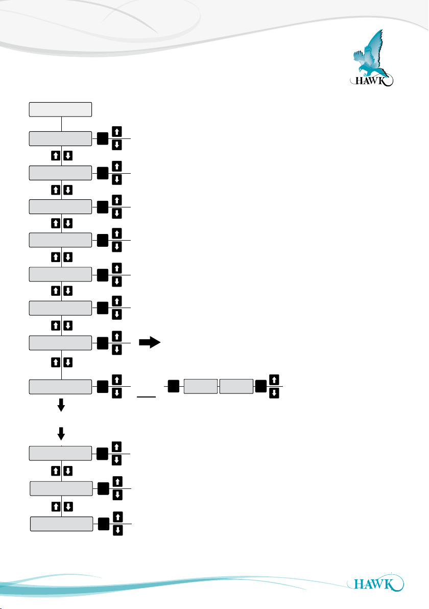
Output Adjustment Setup Menu
Sultan Acoustic Wave Series
Output Adj
Fill Damp
Empty Damp
4mA Adj
20mA Adj
Analog
Simulate
Comms Type
Rly Mode 1
Continues with Rly Modes 2-5 all with same menu as Rly Mode 1
CAL
CAL
CAL
CAL
CAL
CAL
CAL
CAL
Adjust Fill Damping
0-999
Adjust Empty Damping
0-999
Adjust 4.00mA for remote indicator
Adjust 20mA for remote indicator
Flip the high/low output to 4-20mA or 20-4mA
Simulate distance with 4-20mA change
See Comms Types on page 31
DEN
EN
FS
OFF
CAL
RlyL1 RlyL2
CAL
35
L1 = Relay ON dist.
L2 = Relay OFF dist
Bk Light
DispChar
V in Chk
32
CAL
CAL
CAL
Switch on/off LCD backlight
Adjust number of characters per line on display 8 or 12
When active the unit will switch to failsafe mode if input
voltage drops below required power. When not active
unit will display ‘V fail’ but not enter failsafe mode.
Press RUN twice to revert to normal operation
Page 33

Output Adjustment Parameters
Sultan Acoustic Wave Series
Output Adjustment settings configure Analog, Relay and communication settings.
You can also adjust the fill and empty damping for smoother mA output readings
Fill & Empty Damping
Allows the user to define how quickly the unit
responds to changes in the measured level. A low
damping value gives a fast response and a high
damping gives a slow response. The damping limits
are from 0 to 999. Eg: If you set the damping to a
value of 10, the displayed distance will be a rolling
average of the last 10 pulses. The displayed distance
includes the 4-20mA output and the default display
mode value. Generally it is recommended this value
is not lower than 5-10 for fast filling applications.
4mA Adj & 20mA Adj
Whilst the display shows ‘4mA Adj’ or ‘20mA Adj’,
the analog (4-20mA) current output will be forced
to its respective 4mA or 20mA state. The actual
loop current can be measured with an external
meter and calibrated exactly by pressing the UP or
DOWN arrows until the external meter reads exactly
4.000mA or 20.000mA. Pressing the CAL button will
store the calibration in the instruments memory.
Analog
4-20/20- 4mA The analog current output of the
instrument can be set to act in the normal (4-20mA) or
reverse (20 -4mA). The default condition is 4 -20mA,
where the furthest distance from the transducer (low
level) is output as 4mA, and current increases with
filling to the closer (high level) span point of 20mA .
Simulate
(Y/N): Select Y to access measurement simulation
mode. In simulation mode, the UP and DOWN arrow
keys vary the distance on the display. The current
output and any relays used will behave exactly as
they should do if the measured distance (in S PAC E
mode without damping) was that shown on the display.
This mode can be used to test correct behavior of
outputs, or externally connected equipment.
Relays
Allows the user to set the relays for switching.
The relays are programmed in a distance from the
transducer face to the position where switching is
required. Relays work in the following manner:
OFF The relay will always remain off
The relays can be programmed to energise (EN) or
de-energise (DEN) depending on the product level in
the vessel being monitored.
FS If FS is selected, the relay will operate as a
fail safe relay. The relay will be energised at
all times and will de-energise if the ultrasonic
switch goes in to failsafe condition or if
anything inter feres with the unit’s ability to
keep the relay energised.
See also ‘Relay Functions’ for fur ther information
about the Relay switching on the next page.
Bk Light
Switch on/off LCD backlight
DispChar
Adjust number of characters per line 8 or 12. Some
older units may have an 8 character display only.
V in Chk
The Sultan automatically detects if the input voltage
below 9.5V for 234 wire units and 7V for 2 wire units.
When this mode is active the unit will begin its failsafe
routine and eventually display V fail. When not active
the unit will still display the message ‘Input voltage
too low’.
33
Page 34
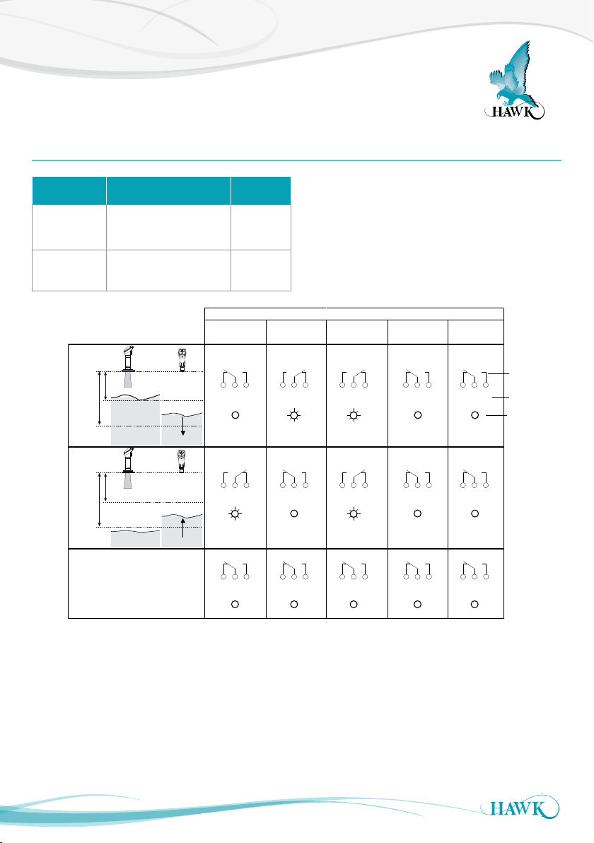
Relay Switch Actions
Sultan Acoustic Wave Series
Relay 1 - 5
Sub-Menu Description Options
RlyL1 1 - 5
RlyL2 1-5
Adjust Relay switch point
(L1 must be < L2)
Adjust Relay switch point
(L2 must be > L1)
L1
L2
L1
L2
Above L1 or
HIGH LEVEL or
Below L2 or
LOW LEVEL or
POWER FAILURE
State 1
State 2
between L1 and
L2 after passing
above L1.
FALLING LEVEL
between L1 and
L2 after passing
below L2.
RISING LEVEL
Adjustable
Adjustable
Energise
EN
NC NOCOM
NC NOCOM NC NOCOM NC NOCOM NC NOCOM NC NOCOM
DeEnergise
DEN
• Set Relay Parameters in Output Adjustment menu
• The two relay levels are RlyL1 and RlyL2
• The display will show RlyL1 1, the last 1 indicated
the Relay number (eg 1 to 5)
• L1 and L2 distances are measured from the
transducer face
NC NOCOM
NC NOCOM
Relay Action
FailSafe
system operating
normally
FS
NC NOCOM
NC NOCOMNC NOCOM
FailSafe
power/system/
FS
measurement failure
NC NOCOM
NC NOCOM
OFF
NC NOCOM
NC NOCOM
Relay Status
Remote Amplifier
terminal function
labels
LED Status
34
Page 35
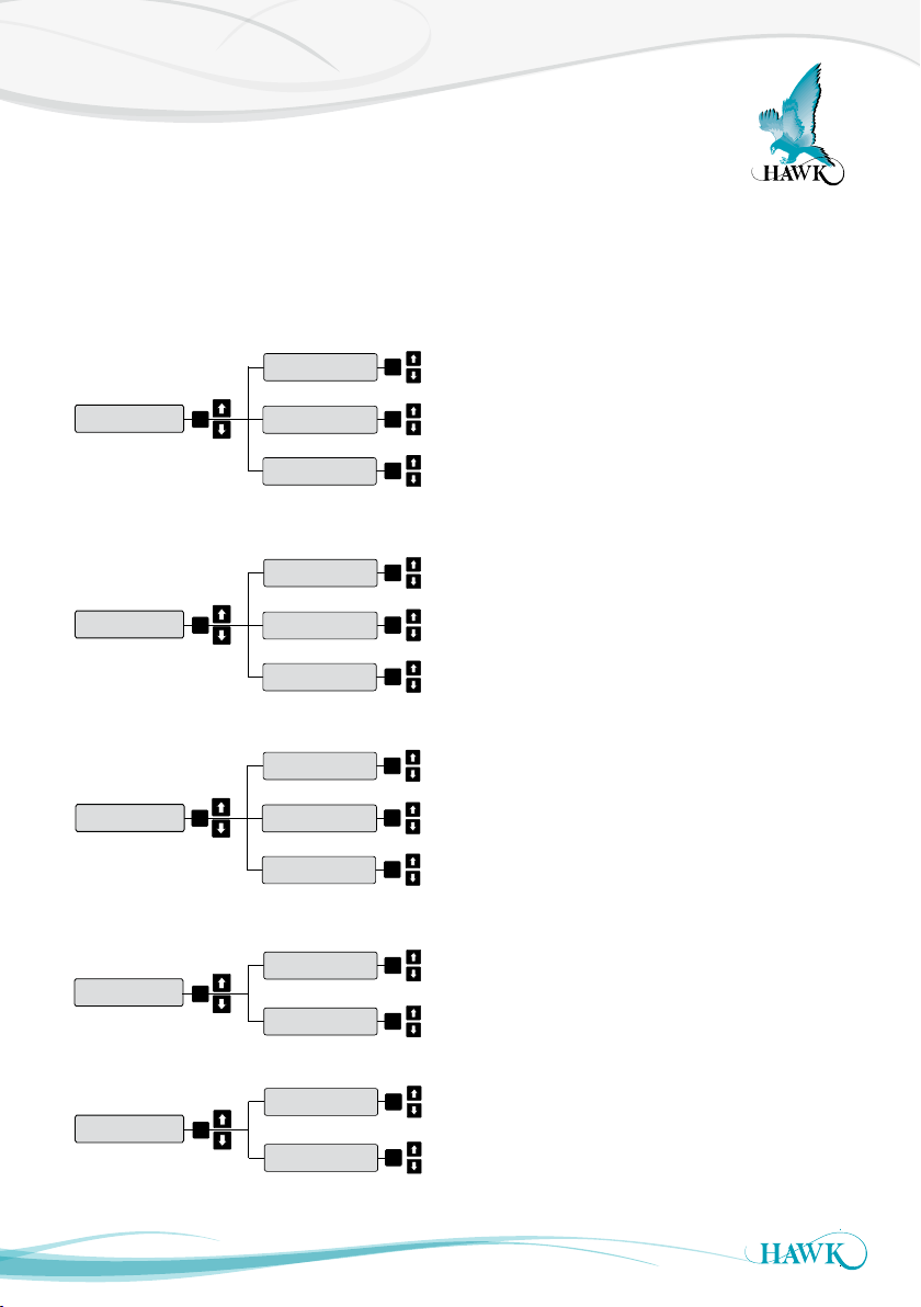
Comm Types Setup Menu
Sultan Acoustic Wave Series
All HAWK products come standard with Modbus. If a unit supports additional communications protocols, it
will be indicated on the wiring label inside the unit and the par t number.
Foundation Fieldbus and Profibus PA have stand alone manuals located in the downloads-manuals section
of www.hawkmeasure.com
FF / PA
Fieldbus
Profibus PA
DeviceNet
Profibus
Profibus DP
HART
Device ID
CAL
Baud Rate
F BusAdd
Device ID
CAL
Baud Rate
F BusAdd
Device ID
CAL
Baud Rate
F BusAdd
Device ID
CAL
Baud Rate
CAL
CAL
CAL
CAL
CAL
CAL
CAL
CAL
CAL
CAL
CAL
35
Modbus
Device ID
CAL
Baud Rate
CAL
CAL
Page 36

Modbus
Sultan Acoustic Wave Series
Modbus setup & basic spans & diagnostic registers for HAWK Sultan Series instruments v3.85
and later.
Protocol: Modbus RTU (2 wire)
Speed: 19200 Baud
Data bits: 8
Parity: None
Stop Bits: 1
HAWK Sultan series units act as ‘slave’ devices on a
Modbus network.
Units are shipped from the factory with a default
Modbus address of 1. The Modbus address of any
unit can be changed individually if units are to be
connected in a multi-drop network. Each address
number must only be used once on any network
(possible addresses are 1-255).
Diagnostic Block (Read Only): *Can be read as
Singles or any Block wholly within the limits of this
range of addresses*
40123 - LOW LEVEL span set point in mm
40124 - HIGH LEVEL span set point in mm
40125 - DISPLAYED DISTANCE (DISTANCE) in mm
40127 - NEW DISTANCE (E-DISTANCE) in mm
40128 - CONFIRM DISTANCE (C- DISTANCE) in mm
40129 - ECHO SIZE in Volts/102
40130 - GAIN at Echo detection point in %/7.5
40131 - NOT USED (Gain Limit)
40132 - RECOVER GAIN in %/7.5
40133 - NOISE in %/7.5
40134 - TEMPER ATURE in Degrees K /10
((DegreesC - 273.2)/10)
40136 - CONFIRM COUNTER current value
40137 - HOLD COUNTER current value
40139 - WINDOW FORWARD POSITION in mm
40140 - WINDOW BACK POSITION in mm
Span Adjustment (Read/Write) MUST Read/ Write
SINGLES-NOT BLOCKS:
40011 - LOW LEVEL span set point in mm
40012 - HIGH LEVEL span set point in mm
Relay Function Adjustment (Read / Wr ite)
MUST Read/Write SINGLES-NOT BLOCKS:
40051 - Relay 1 Mode setting
0-OFF
1-FS (Failsafe)
2-EN (Energise on Level)
3-DEN (De-Energise on Level)
40052 - Relay 2 Mode setting (see Relay 1)
40053 - Relay 3 Mode setting (see Relay 1)
4005 4 - Relay 4 Mode setting (see Relay 1)
40055 - Relay 5 Mode setting (see Relay 1)
40035 - Relay 1 L1 set point in mm
40036 - Relay 1 L2 set point in mm
40037 - Relay 2 L1 set point in mm
40038 - Relay 2 L2 set point in mm
40039 - Relay 3 L1 set point in mm
40040 - Relay 3 L2 set point in mm
40041 - Relay 4 L1 set point in mm
40042 - Relay 4 L2 set point in mm
40043 - Relay 5 L1 set point in mm
40044 - Relay 5 L2 set point in mm
36
Page 37

Modbus
Sultan Acoustic Wave Series
Extended Parameters (Read/Write) *MUST Read/
Write SINGLES- NOT BLOCKS*:
40059 - DISPLAY UNITS
3-Millimetres
4-Centimetres
5-Metres
6-Feet
7-I nches
40014 - FAILSAFE MODE
0 - 3.5mA
1 - 3.8mA
2 - 20.2mA
3- Last Known
4 - 4.0mA
5 - 20.0mA
40015 - FAILSAFE TIME (seconds)
40016 - APPLICATION TYPE
0 - Liquid
1 - Solid
2 - Slurr y
3 - Position
40017 - FILL RATE (metres per hour/10)
40018 - EMPT Y RATE (metres per hour/10)
40019 - DISPLAY MODE
1 - Volume
2 - Flow
3 - Material %
4 - Material
5 - Space
6 - Differential Output
7 - Average Material
40032 - OFFSET (mm)
40020 - LOCK CODE
40021 - FILL DAMPING
40022 - EMPTY DAMPING
40063 - ANALOG
0 - 4-20mA (4mA low, 20mA high - standard)
1 - 20- 4mA (20mA low, 4mA high - inverted)
40447 - GAIN parameter setting in %/7.5
40448 - GAIN STEP in %/7.5
40449 - DISTANCE STEP (mm)
40450 - THRESHOLD in Volts/100
40451 - BLANKING (mm)
40452 - EMPTY DISTANCE (mm)
37
Page 38
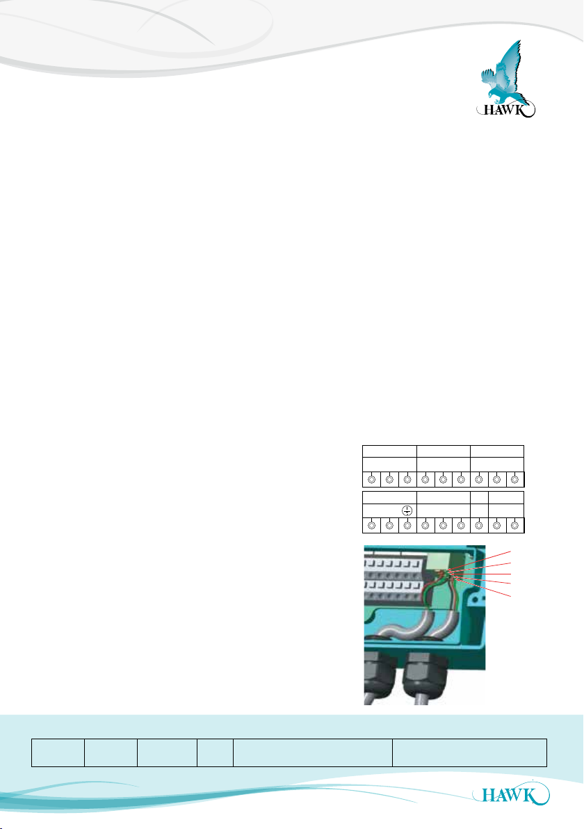
DeviceNet - Setup & Parameters / Wiring
DEVNET COMMS RL1
5. V+
4. CAN_H
3. SHEILD
2. CAN_L
1. V-
Sultan Acoustic Wave Series
Setting the Baud Rate and the
DeviceNet Address
The DeviceNet factory default of Baud Rate and
FBus Address are 125kbps and 63 in a Sultan unit
with. To modify these values follow the instructions
below.
1. Go to the ‘Output Ad’ menu
2. Use the Up and Down push buttons to reach the
CommType parameter
3. Make sure that the C ommTy p e is set to
‘DeviceNet’
4. Press the CAL button twice
5. DeviceID will be displayed - this ID is for Modbus
networking, do not adjust.
6. Use the Down push button to reach the
BaudRate parameter
7. The default value for the BaudRate is 125kpbs.
Press CAL button and use the Up and Down push
buttons to modify this value
8. Press CAL button when finished
9. Use the Down push button to reach the FBusAdds.
The default value of the FieldBus Address is 63.
Press CAL button and use the Up and Down push
buttons to modify this value
10. Press CAL button again when finished
11. Press RUN to save and several times again to
return the unit to operating mode.
Output Data
Profibus/DeviceNet now transmit 18 bytes/9 words,
description of the words is as follows (For firmware
version 5.54 and above).
1. Displayed Distance
(Space Distance is the Primary Variable)
2. Percentage (Percent of Range)
3. Hi Level (Upper Range)
4. Low Level (Lower Range)
5. Status Flags
Bit0 = Echo was received inside the span.
Bit1 = Echo is C onfirmed.
Bit3 = Searching is searching for an Echo.
BitF = Unit has Failed to detect an Echo.
6. Displayed Distance2 (Second Variable)*
7. Percentage2 (Second Percent of Range)*
*Used for Differential output on a Sultan
Integral
ABshld
LI N
Remote
ABshld
AC-IN DEVNET DC-IN
NC
COM
TEST
-
24V+shld GND
NO
+
5. V+
4. CAN_H
3. SHEILD
2. CAN_L
1. V-
Bit F Bit E Bit 3 Bit 1 Bit 0
Failed ~~~~~ Search 0 Echo Cfm : 1 = , True, 0 = False Echo R : 1 = , True, 0 = False
38
Page 39
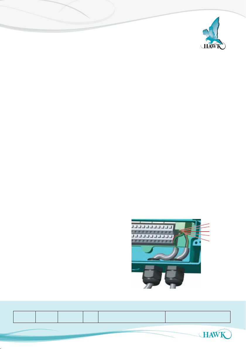
Probus - Setup & Parameters
Sultan Acoustic Wave Series
Setting the Probus DP Address
Factory defaults of FBusAdds is 126 in a Sultan unit
with Profibus CommType. To modify this value follow
the instruction below:
1. Go to the ‘Output Ad’ menu
2. Use the Up and Down push buttons to reach the
CommType parameter
3. Make sure that the C ommTy p e is set to ‘Profibus’
4. Press the CAL button twice
5. DeviceID will be displayed - this ID is for Modbus
networking, do not adjust.
6. Use the Down push button to view the BaudRate
parameter. The value for the BaudRate is selected
automatically and can not be modified.
8. Use the Down push but ton to reach the FBusAdds.
The default value of the FieldBus Address is 126.
Press CAL button and use the Up and Down push
buttons to modify this value.
9. Press CAL button again when f inish.
10. Press RUN several times to return the unit to
operating mode.
Output Data
DeviceNet now transmits 18 bytes/9 words,
description of the words is as follows (For f irmware
version 5.54 and above)
1. Displayed Distance
(Space Distance is the Primary Variable)
2. Percentage (Percent of Range)
3. Hi Level (Upper Range)
4. Low Level (Lower Range)
5. Status Flags
Bit0 = Echo was received inside the span.
Bit1 = Echo is Confirmed.
Bit3 = Searching is searching for an Echo.
BitF = Unit has Failed to detect an Echo.
6. Displayed Distance2 (Second Variable)*
7. Percentage2 (Second Percent of Range)*
*Used for Differential output
Wiring
5. B IN
4. A IN
3. SHEILD
2. B OUT
1. A OUT
Bit F Bit E Bit 3 Bit 1 Bit 0
Failed ~~~~~ Search 0 Echo Cfm : 1 = , True, 0 = False Echo R : 1 = , True, 0 = False
39
Page 40
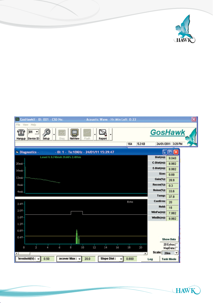
PC Comms - GosHawkII
Sultan Acoustic Wave Series
HAWK provides free in-house developed soft ware called GosHawkII. This software is suppor ted by all current
products and is used by HAWK Engineers & HAWK authorised representatives during commissioning, testing
and monitoring unit performance.
The software allows easy access to unit setup menus using a PC rather than the keypad and gives a visual
representation of what the unit is seeing (all echoes which pass the unit filter), transmitting and displaying on
the unit face.
The best and easiest way to set up, troubleshoot and monitor a HAWK unit is via GosHawkII.
To connect to a unit using this software you need either a HawkLink modem or HawkLink USB connector.
For a multidrop network GosHawkII uses a Modbus ID to identify each unit.
40
Page 41
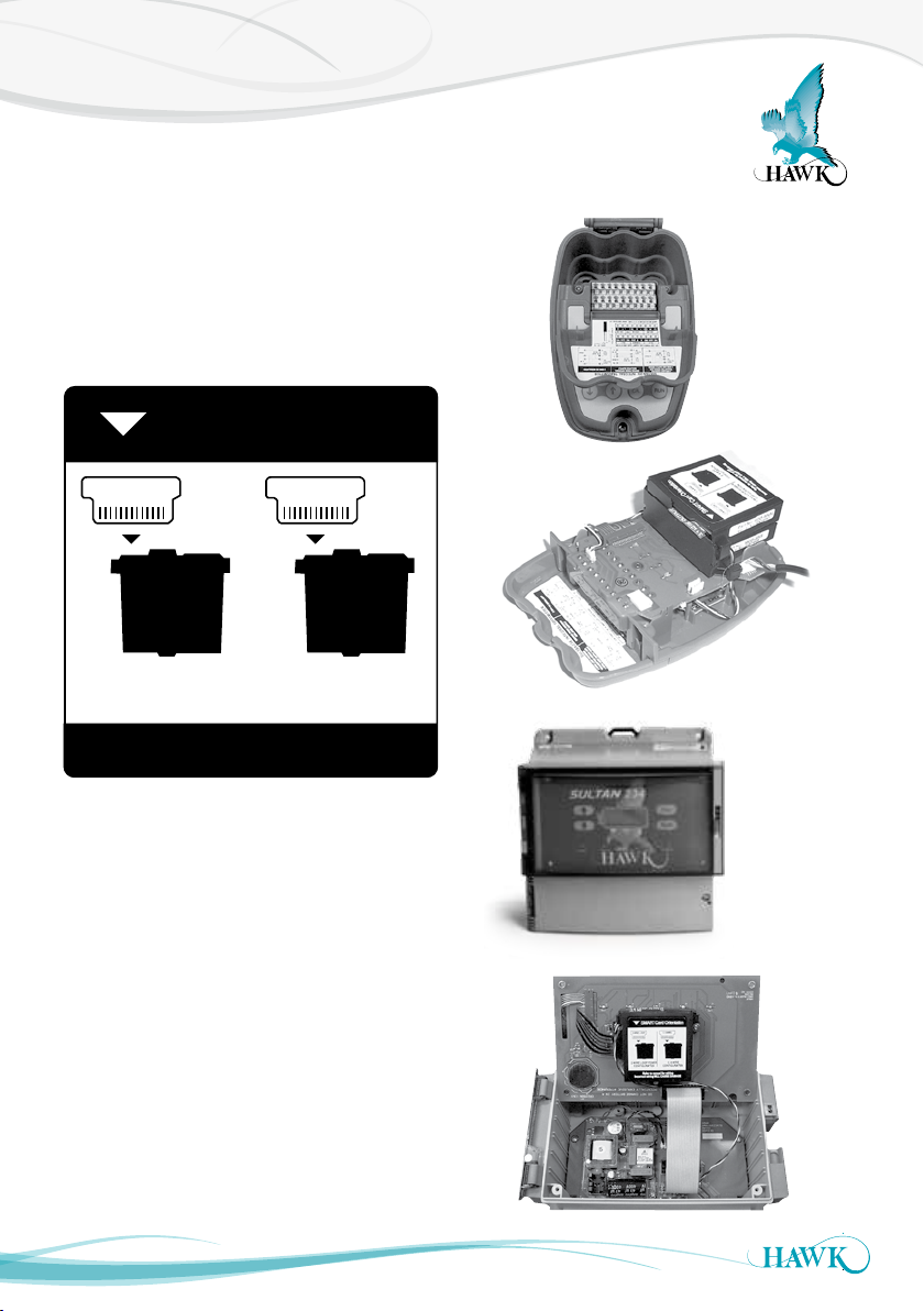
Converting 234 Wire to 2 Wire Loop
Sultan Acoustic Wave Series
Sultan234 units can be switched to 2 wire loop mode
by flipping a SMART card on the analogue module.
The module is located behind the display and will
have MOD-AN moulded on the plastic as well as a
sticker indicating the orientation of the SMART card
for both modes
SMART Card Orientation
2 WIRE LOOP 3, 4 WIRE
Remove screws
2 WIRE LOOP POWER
CONFIGURATION
3, 4 WIRE
CONFIGURATION
Refer to manual for wiring
Incorrect wiring WILL CAUSE DAMAGE
The card is secured by a small brown plastic lock.
Gently lift both tips of the plastic lock until they click
up to release the lock. Gently lift the card out and flip
to the required mode. Place the card back in and
re-lock down the plastic bracket.
The procedure is delicate, it is recommended to be
performed in a workshop or lab and not in the field.
41
Remove screws
Page 42

Troubleshooting
Sultan Acoustic Wave Series
39. Unit displays or transmits distance that is higher than the actual level / unit is locking on high level
40. Output doesn’t match level during filling / emptying
40. Output is erratic / inconsistent
40. Replacing the amplifier or transducer
41. Hardware checks - Voltage & Resistance (Remote & Integral)
42. Error Codes
43. Contacting HAWK
42
Page 43
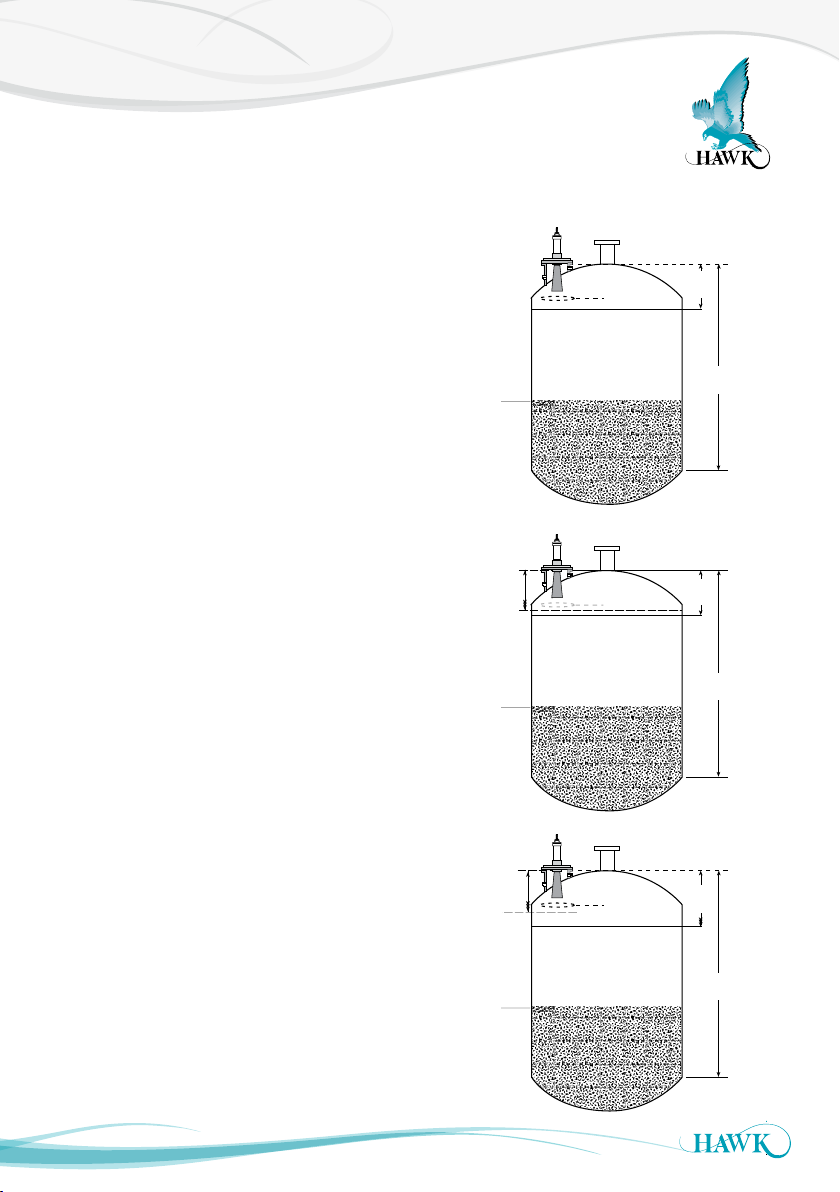
Displays Distance
Sultan Acoustic Wave Series
Unit displays or transmits distance that is higher than the actual level / unit is locking on
high level
1. Check the mounting conditions within the vessel.
Are there any obstacles in front or near the front
& side of the face of the transducer? If so, consider
moving the unit to a different location.
2. Check the distance of the false echo. If this is
above your high level you can change the unit
sensitivity to the echo. In ‘Advanced’ change the
‘Dist Step3’ to a distance further than the echo, and
lower the ‘Gain Step3’ to make the unit less
sensitive for the ‘Dist Step’ distance.
If the echo is below the ‘High Level’, you can still
modify the Distance & Gain Steps3 to solve the
problem. Consider lowering the ‘High Level’ value
below the ‘Dist Step3’.
If you cannot do this, lower the ‘Gain4’ value (also
located in ‘Advanced’) incrementally until the unit
cannot see the problem echo.
Lowering the Gain4 % will affect overall sensitivity
of the unit. It will reduce unit capabilit y. If you need
to lower this value by 5-10% to avoid the unit
locking onto an obstacle you must consider step 1
(adjusting mounting location).
3. You can extend the ‘Blanking’ (T X Setup) distance
to ‘blank’ the echo entirely. Anything within this
‘Blanking’ distance will NOT be tracked by the
unit under any circumstances. Consider this in
case of accidental over filling. Never have the
‘Blanking’ distance longer than the ‘High Level’.
Extend Distance
Step beyond
incorrect level.
Lower Gain Step%
Extend
Blanking
Distance
Actual
Level
Actual
Level
Actual
Level
Level unit
tracking
Level unit
tracking
Level unit
tracking
High
Level
High
Level
Lower
High
Level
Low
Level
Low
Level
Low
Level
43
Page 44
Output
Sultan Acoustic Wave Series
Output doesn’t match level during lling /
emptying
Ensure the span programmed into your PLC matches
the span (high & low level) programmed into the unit
Ensure the Fill Rate and/or Empty rate is set fast
enough for your application.
If the unit is ‘locked’ showing a higher level than see
‘Unit displays or transmits distance that is higher than
the actual level’.
Ensure resistance load is within HAWK specification
on analog wires.
For analogue output related problems it is important to isolate the Sultan
(disconnect from the network) and use a multimeter to read the analogue terminals directly.
Output is erratic / inconsistent
Increase the ‘damping’ values to stabilise unit
response times. The settings are in ‘Output
Adjustment’ menu as ‘FillDamp’ and ‘EmtyDamp’.
If material being measured forms angle of repose try
adjusting Transducer mounting angle to get better
reflections
Replacing a Transducer or Amplier
If replacing either the amplifier or transducer you
must re- enter your application settings into the unit.
Consider stocking spare amplifiers and transducers
to avoid potential down time.
44
Page 45

Unit Voltage Specs & Checks
Sultan Acoustic Wave Series
Remote & Integral
Sultan 234
Specified ranges (supply dependent): 90-260VAC,
12-30VDC, 36- 60VDC). For suspected power issues
ensure user supply is appropriate & consistent.
If using AC power you can check the power supply
for faults by reading the DC +/- terminals with a
multimeter set to DC. This terminal will produce 15-
16VDC stable. If this value is lower or inconsistent
you may a problem with the internal power supply.
Unit per formance will be affected if the unit detects
voltage below 9VDC. If ‘V in chk’ is on the unit will
trigger its failsafe routine. If V in chk is off the unit will
display V fail on the LCD.
Sultan 2
Specified ranges: 12-30VDC.
Unit per formance will be affected if power drops
below 7VDC. If ‘V in chk’ is on the unit will trigger its
failsafe routine. If V in chk is off the unit will display V
fail on the LCD.
Transducers
The Transducer power (red wire) should draw
8-10VDC. If this figure is too high or too low check
Sultan power & supplied power as above.
Check Resistances between transducer wires
(approximate values):
Black - Blue = 15.6Kohms
Black - White = 15.6Kohms
Resistances between transducer terminals
(approximate values):
Black - Blue = 16.2Kohms
Black - White = 16.2Kohms
45
Page 46

Troubleshooting
Sultan Acoustic Wave Series
Error Codes 01 - 04
Error 01: Amplifier/ Transmitter can not communicate
with transducer.
Wiring:
Check the terminals for a loose or incorrect
connection (including junction box/cable extensions).
Check the cables for any signs of damage. Ensure
any customer supplied cable meets HAWK
specifications.
If using junction box extension trace the 8-9VDC from
the red/black amplifier terminals to the transducer
to ensure wires are correct. If using a junction box
ensure you follow Hawk specification for extending
cable.
When the unit powers up does the transducer pulse
once? If it does this indicates the transducer has
powered correctly (red/black terminals). Check the
comms wiring (blue/white). If the transducer does
not pulse once when the red/black wires are applied
(wires must be the potted Transducer wires) the
Transducer most likely has a fault or damage.
Has the transducer ID number been modified while
connected to a different transmitter? Re-connect the
unit to the previous transmitter and change the ID via
Quickstart/SenAdd CAL TxAdds.
Error 01
It can also be caused by power supply related issues.
See ‘Unit Voltage Specs & Checks’.
Error 02:
Communication data corruption between Transmitter
and Transducer.
It can be a result of noise in data lines or one of data
lines (white or blue) being open circuit.
Make sure wiring is correct especially look to the
screen (ear th).
Ensure you are using quality shielded instrument
cable.
If using a junction box ensure you follow HAWK
specification for extending cable.
Integral units with Error 02 will be an internal problem,
contact your Hawk representative.
Error 03
Specif ic comms mode is selected (eg Profibus, FF)
but comms module is not connected or responding.
Check your unit part number to ensure it has correct
comms. If you do not have additional comms (option
X) then select Modbus.
Error 04
Amplif ier is programmed with incorrect soft ware.
Contact your local suppor t.
In general Error Code 01 indicates there is NO
communication and Error Code 02 says there IS
communication, but not of sufficient qualit y to be
read reliably.
46
Page 47

Technical Support
Sultan Acoustic Wave Series
Before contacting Hawk for assistance please write down the ‘Diagnostics’ displayed on the unit to assist with
suppor t speed. See ‘DIAGNOSTICS & SOFTWARE OVERVIEW’ for further information.
Also include a diagram or drawing of the vessel marked with where the transducer is installed along with
photographs of the installation and what is below the transducer.
47
Page 48

Part Numbering
Sultan Acoustic Wave Series
Sultan Remote Transmitter
Model
AWR2 Remote 2 Wire, No relays, 12-30VDC only, Modbus
AWR234 Remote 2 / 3 / 4 Wire, 5 relays, Modbus
Housing
S Polycarbonate
Power Supply
B 12-30VD C
C
U
Additional Communications (PC comms GosHawk standard)
S
X 4-20mA analogue
H
I
A Profibus PA
P
F Foundation Fieldbus
D
E
This option is no longer available
X Option no longer available
Approval Standard
X Not Required
i0
A0
i20
A20
A22 ATEX Grp II Cat 3 GD T85°C IP67 Tamb -40°C to 70°C
GP CSA Equip Class 2; Pollution deg 2; Tamb -20°C to 75°C
RN
Position Slave / Crane Master
X Not Required
PS
CM
AWR234 S U X X X X
1
36- 60VDC
1
12- 30VDC a nd 90 -260VAC
1
No additional communications (5 Relays, Modbus)
2
4-20mA analogue with HART 2 wire
1
4 -20mA analogue with HART Isolated 4 wire
1
Profibus DP
1
DeviceNet
1
4-20mA with Modbus over Ethernet TCP/IP
3
IECEx Zone 0 Ex ia IIA T4 IP67 Tamb -20°C to 70°C
3
ATEX Grp II Cat 1 GD IP67 EEx ia IIA T4
3
IECEx Zone 20 DIP A20 TA85C IP68 Tamb -20°C to 75°C
3
ATEX Grp II Cat 1 D T85°C IP67 Tamb -20°C to 75°C
3
CSA Class I; Div 1/2; Group D; Zone 0; AEx / Ex ia IIA; T4
1
Position Slave
1
Crane Master
1
Model AWR234 only
2
Model AWR 2 only
3
Model AWR 2 only.
Communication Option W, X, H only
(Ordinary Locations)
48
Page 49

Part Numbering
Sultan Acoustic Wave Series
Sultan Remote Transducer 3” and 3.5”
Model
AWRT Acoustic Wave Remote Transducer
Transducer Frequency
30 30 kHz for applications up to 15m for 3” (Cone required1)
20 20kHz for applications up to 20m, 3” only (Cone required1)
15 15kHz for applications up to 30m, 3” only (Cone required1)
10 10kHz for applications up to 40m, 3.5” only (Cone required1)
09 9kHz Positioning / Position Slave applications up to 180m (Cone required1)
05 5kHz for applications up to 60m, 3.5” only (Cone required1)
04 4kHz Positioning / Position Slave applications up to 180m (Cone required1)
Process Temperature - Facing material selection
S Polyolefin 80°C (176°F)
T Teflon 80°C (176°F)
Y Titanium 80°C (176°F)
Transducer Housing Material
4 Polypropylene
Back Cap Mounting Thread Standards
X Not Required (Standard Flange Mount)
TB BSP
Back Cap Mounting Thread Sizes
X Not Required (Standard Flange Mount)
3 0 3” BSP
50 3.5” BSP
Approval Standard
X Not Required
i0 IECEx Zone 0 Ex ia IIA T4 IP67 Tamb -20°C to 70°C
A0 ATEX Grp II Cat 1 GD IP67 EEx ia IIA T4
i1 IECEx Zone 1 Ex mb II IP68 T5(Tamb -20°C to 65°C) T6(Tamb -20°C to 5 0°C)
A1 ATEX Grp II Cat 2 GD EEx m II IP68 T5(Tamb -20°C to 65°C) T6( Tamb -20°C to 50°C)
i20 IECEx Zone 20 DIP A20 TA85C IP68 Tamb -20°C to 75°C
A 20 ATEX Grp II Cat 1 D T85°C IP67 Tamb -20°C to 75°C
A 22 ATEX Dust (Grp II Cat 3 D T8 5C IP67)
GP CSA Equip Class 2; Pollution deg 2; Tamb -20°C to 75°C (Ordinary Locations)
RN CSA Class I; Div 1/2; Group D; Zone 0; AEx / Ex ia IIA; T4
KN CSA Class II; Div 2; Group F&G; Class III; T6 T85 for Tamb -20°C to 75°C
QN CSA Class II; Div 1; Group E, F&G; Ex mb II; T5(T100) for Tamb -20°C to 65°C;
T6( T85) for Tamb -20°C to 50°C
Connection
C IP68 Sealed unit with cable
Cable Length
6 6m cable
15 15m ca ble
30 30m cable
50 50m cable
Mounting Accessories
X Not Required
CS End Cap Cable Suspension
Software Options
X Not Required
FP Fast Pulsing
PS Position Slave (Requires Position Slave A mplif ier)
AWRT 10 T 4 X X X C 6 X X
49
Page 50

Part Numbering
Sultan Acoustic Wave Series
Sultan Remote Transducer 2” Version
Model
AWRT Acoustic Wave Remote Transducer
Transducer Frequency
50 50kHz for liquid applications up to 5m (Cone required
40 40kHz for liquid applications up to 7m (Cone required
30 30kHz for liquid applications up to 11m (Cone required
Process Temperature - Facing material selection
T Tefzel 80°C (176°F)
Transducer Housing Material
6 Tefze l
Thread Standard
TB BSP
TN NPT
Thread Size
20 2” thread
Approval Standard
X Not Required
i0 IECEx Zone 0 Ex ia IIA T4 IP67 Tamb -20°C to 70°C
A0 ATEX Grp II Cat 1 GD IP67 EEx ia IIA T4
i1
A1
IECEx Zone 1 Ex mb II IP68 T5(Tamb -20°C to 65°C) T6(Tamb -20°C to 50°C)
ATEX Grp II Cat 2 GD EEx m II IP68 T5(Tamb -20°C to 65°C) T6(Tamb -20°C to 50°C)
i20 IECEx Zone 20 DIP A20 TA85C IP68 Tamb -20°C to 75°C
A20 ATEX Grp II Cat 1 D T85°C IP67 Tamb -20°C to 75°C
A22 ATEX Grp II Cat 3 GD T85°C IP67 Tamb -40°C to 70°C
GP CSA Equip Class 2; Pollution deg 2; Tamb -20°C to 75°C
RN CSA Class I; Div 1/2; Group D; Zone 0; AEx/Ex ia IIA; T4
KN CSA Class II; Div 2; Group F&G; Class III; T6 T85 for Tamb -20°C to 75°C
QN CSA Class II; Div 1; Group E, F&G; Ex mb II; T5(T100) for
Tamb -20°C to 65°C; T6( T85) for Tamb -20°C to 50°C
Connection
C IP68 Sealed unit with cable
Cable Length
6 6m cable
15 15m cable
30 30m cable
50 50m cable
Mounting Accessories
X Not Required
CS Cable Suspension on end cap
Software Options
X Not Required
1
1
1
)
)
1
See ‘Transduc er / Cone /
Flange combination table
)
(Ordinary Locations)
AWRT 30 T 6 TB 20 X C 6 X X
50
Page 51

Part Numbering
Sultan Acoustic Wave Series
Sultan Integral 3” and 3.5”
Model
AWI2 Integral 2 Wire, No relays, Modbus
AWI234 Integral 2 / 3 / 4 Wire, 2 relays, Modbus
Housing
S Valox 357U
Power Supp ly
B 12-30VDC
U
Transducer Frequency
30 30kHz for applications up to 11m for 2” and 15m for 3” (Cone required
20 20kHz for applications up to 20m, available in 3 ” only (Cone required
15 15kHz for applications up to 30m, available in 3” only (Cone required
10 10kHz for applications up to 40m, available in 3.5” only (Cone required
09 9kHz for Positioning / Position Slave applications up to 180m (Cone required
05 5kHz for applications up to 60m, available in 3.5” only (Cone required
04 4kHz for Positioning / Position Slave applications up to 180m (Cone required
Process Temperature - Facing material selection
S
T
Y
Transducer Housing Material
4 Polypropylene
This option is no longer available
X Option no longer available
This option is no longer available
X Option no longer available
Additional Communication
S1 No additional communications (5 Relays, Modbus)
X 4-20 mA analogue
H
I
A Profibus PA
F Foundation Fieldbus
Approval Standard
X Not Required
i0
1
Model AWI234 only
A0
2
Transducer Frequency 04, 05, 09, 10 only
i20
3
Transducer Frequency 10, 15, 20, 30 only
A20
4
Transducer Frequency 15 only
A22 ATEX Grp II Cat 3 GD T85°C IP67 Tamb -40°C to 70°C
5
Model AWI2 only. Communication Option W, X, H only
Soft ware Options
6
See Transducer / Cone / Flange combination table
X Not Required
AWI234 S U 10 S 4 X X X X X
1
12-3 0VDC a nd 9 0 -2 60VAC
2
Polyolefin 80°C (176°F)
3
Teflon 80°C (176°F)
4
Titanium 80°C (176°F)
1
6
)
6
)
6
)
6
6
)
5
4-20mA analogue with HART 2 wire
4-20 mA analogue with HART Isolated 4 wire
5
IECEx Zone 0 Ex ia IIA T4 IP67 Tamb -20°C to 70°C
5
ATEX Grp II Cat 1 GD IP67 EEx ia IIA T4
5
IECEx Zone 20 DIP A 20 TA85C IP68 Tamb -20°C to 75°C
5
ATEX Grp II Cat 1 D T85°C IP67 Tamb -20°C to 75°C
)
6
)
6
)
51
Page 52

Part Numbering
Sultan Acoustic Wave Series
Sultan Integral 2”
Model
AWI2 Integral 2 Wire, No relays, 12-30VDC only, Modbus
AWI234 Integral 2 / 3 / 4 Wire, 2 relays, Modbus
Housing
S Valox 357U
Power Supply
B 12-30VDC
U
Transducer Frequency
50 50kHz for
40 40kHz for liquid applications up to 7m (Cone required6)
30 30kHz for liquid applications up to 11m (Cone required6)
Process Temperature - Facing material selection
T Tefzel 80°C (176°F)
Transducer Housing Material
6 Tef z e l
Thread Standards
TB BSP
TN NPT
Mounting Thread Sizes
20 2” thread
Additional Communication
S
X 4-20mA analogue
H2 4-20mA analogue with HART 2 wire
`I1 4 -20mA analogue with HART Isolated 4 wire
A Profibus PA
F Foundation Fieldbus
Approval Standard
X Not Required
i0
A03 ATEX Grp II Cat 1 GD IP67 EEx ia IIA T4
1
Model AWI234 only
i203
2
Model AWI2 only
A203 ATEX Grp II Cat 1 D T85°C IP67 Tamb -20°C to 75°C
3
A 22 ATEX Grp II Cat 3 GD T85°C IP67 Tamb -40°C to 70°C
Model AWI2 only. Communication Option W, X, H only
6
Software Options
See Transducer / Cone / Flange combination table
X Not Required
AWI234 S U 40 T 6 TB 20 X X X
1
12-30VDC an d 9 0-260VAC
liquid applications up to 5m (Cone required
1
6
)
No additional communications (5 Relays, Modbus)
3
IECEx Zone 0 Ex ia IIA T4 IP67 Tamb -20°C to 70°C
IECEx Zone 20 DIP A20 TA85C IP68 Tamb -20°C to 75°C
52
Page 53

Part Numbering
Sultan Acoustic Wave Series
Flange Selection
F Flange
Dimension Standard
A ANSI
D DN
J JIS
Flange Sizes
2N Matches 2” NPT threaded units
2B Matches 2 ” BSP threaded units
3 3” acoustically isolated flange
4 4” acoustically isolated flange
6 6” acoustically isolated flange
8 8” acoustically isolated flange
10 10” acoustically isolated flange
Flange Mounting Position
A Cone Mounted (standard)
C Angled flange piece only
Flange Material
4 Polypropylene
F A 4 A - 4
Additional Flange Options
FA8A-4-C4 8” ANSI, polypropylene
FA10A- 4- C 4 10” ANSI, polypropylene
FA6D5 0-4 6” ANSI, polypropylene
FA8D5 0- 4 6” ANSI, polypropylene
FA10 D50- 4 6” ANSI, polypropylene
2
2
2
1
Cone Selection
C Focaliser Cone
Cone Type
02N C04 cone for 2” NPT transducer
02B C04 cone for 2” BSP transducer
04 4” cone for 20kHz and
3” 30kHz transducers
08-15 8” cone for 15kHz
08-10 8” cone for 10kHz
10-15 10” cone for 15kHz
10-10 10” cone for 10kHz and 9Hz
10-05 10” cone for 5kHz and 4kHz
Cone Material
4 Polypropylene
1
7A Carbon Fibre. Includes matching
ANSI Flange (4”, 8” or 10”)
7D Carbon Fibre. Includes matching
DN Flange (4”, 8” or 10”)
7J Carbon Fibre. Includes matching
JIS Flange (4”, 8” or 10”)
8 Polyurethane
C 04 - 4
Additional Cone Options
C04-4-ZOD90 C04- 4 trimmed to fit 90mm ID nozzle.
C03-4 -Z Cone and coupling to fit 72mm ID
nozzle for 20kHz and 30kHz (T4).
1
1
1
Important: See Transducer / Cone / Flange combination table for valid part combinations
2
See ‘Flange Dimension Standards’ table for full Flange specification
53
Page 54
Part Numbering
Sultan Acoustic Wave Series
Transducer / Cone / Flange Combination Table
• Each line represents fit ting combinations. Flange Dimension Standard A , D or J replaces underscore (_ ) position
Transducer Cone Flange Option 1 Flange Option 2 Flange Option 3 Flange Option 4
50 / 40kHz C02 F_ 3 A F_ 4A
30kHz (T6) C02 F_ 3A F_4A
30kHz (T4)
Back Cap Mount (TB30)
20kHz
Back Cap Mount (TB30)
15kH z
Back Cap Mount (TB30)
9 / 10kHz
Back Cap Mount (TB50)
4 / 5kHz
Back Cap Mount (TB50)
C03-4-Z F_3A
C04 F_3A F_ 4 A F_6A F_8A-4-C4
F_4A FA6 A
C03-4-Z F_3A
C04 F_3A F_ 4 A F_6A F_8A-4-C4
F_4A F_ 6 A
C04 F_4A F_ 6 A
C08 F_8A F_10 A F_6 D 5 0 - 4
C10 F_ 8 A F_10 A F_ 6 D 50- 4
F_4A F_ 6 A
C08 F_8A F_10 A F_6 D 5 0 - 4
C10 F_ 8 A F_10A F_ 6 D5 0 -4
F_6 D 5 0 - 4 F_8D 5 0 - 4 F_10D5 0 - 4
C08 F_ 8 A F_10A F_ 6 D5 0 -4
C10 F_ 8 A F_10A F_ 6 D5 0 -4
F_6 D 5 0 - 4 F_8D 5 0 - 4 F_10D5 0 - 4
Accessories
HAWKLink Data Modem
Model
HLR Remote stand alone HAWKLink system
Power Supply
B 12- 30 VD C
U 12-30VDC and 9 0-260VAC
Net w ork Type
G3 3G Autoband
Sim Card
S3 Australian Sim Card expires after 3 month
S12 Australian Sim Card expires after 12 month
X Not Required
HLR U G3 S3
54
Not Recommended
HAWKLink USB PC connector for GosHawkII
HAWKLink-USB
Stainless Steel Sunhood
SUNHOOD
Junction Box for twin Transducer applications
AWR T-JB - 01
AWRT-JB-06 (includes 6m cable)
Extra Cable (Belden 3084A)
CA-T XCC-R-C15 15m cable
CA-TXCC-R- C30 30m cable
CA-TXCC-R- C5 0 50m cable
CA-TXCC-R- C10 0 100m cable
Page 55

Specications
Sultan Acoustic Wave Series
Frequencies
• 4kHz, 5kHz, 9kHz, 10kHz, 15kHz, 20kHz, 30kHz,
40kHz, 50kHz
Operating Voltage
• 12-30VDC (residual ripple no greater than 100mV)
• 90-265VAC 50/60Hz
• 36- 60VDC
Power Consumption
• <10VA @ 240VAC
• <3W @ 24VDC
• <6W @ 48VDC
Analog Output
• 4-20mA (750 ohms @ 24Vdc User supply, 250 ohms
internally driven)
Communications
• GosHawk, HART, Modbus, Modbus over Ethernet
TCP/IP, Profibus DP, DeviceNet,
Foundation Fieldbus, Profibus PA. Multidrop mode
can address 1-250 units over 4 wire
Relay Output
(2) Integral (5) Remote
• Form ‘C’ (SPDT) contacts, rated 0.5A at 240VAC
non-inductive.
• All relays have independently adjustable dead
bands.
• Remote fail-safe test facility for one relay.
Blanking Distance
See ‘Minimum Measurement Range’ section
Maximum Range
• 5m (16ft) 50kHz liquids
• 7m (22ft) 40kHz liquids
• 10m (33ft) 30kHz liquids, 5m (16ft) solids
• 20m (65f t) 20kHz liquids/slurries, 10m (33ft) solids
• 30m (98ft) 15kHz liquids/slurries, 20m (65ft) solids
• 60m (196ft) 10kHz liquids/slurries 40m (165ft) /
powders/solids
• 60m (196ft) 5kHz liquids/slurries/powders/solids
• 180m (588ft) 4/9 kHz for extended range position
applications
Resolution
• 1 mm (0.04”) 50, 40, 30,20, 15, 10, 5kHz
• 4 mm (0.2”) 9, 4kHz
Sensor Accuracy
• +/- 0.25% of measured range
Operating Temperature
• Integral System -40°C (-40°F) to 80°C (176°F)
• Remote electronics -40°C (-40°F) to 80°C (176°F)
• Remote transducer - 40°C (-40°F) to 80°C (176°F)
Transducer / Amplier Separation
• Up to 1000m using specified extension cable
Cable
• 4 conductor shielded twisted pair instrument cable.
• Conductor size dependent on cable length.
• BELDEN 3084A , DEKORON or equivalent.
• Max: BELDEN 3084A = 500m (1640 ft)
• Max: DEKORON IED183A A002 = 350m (980 ft)
Maximum Operating Pressure
• +/- 7.5 PSI (+/- 0.5 Bar)
55
Page 56
Specications / Approvals & Certication
Sultan Acoustic Wave Series
Beam Angle
• 7.5° without focaliser 50kHz/40kHz / 30kHz
• 4° with focaliser 50kHz/40kHz
• 6° with focaliser 30kHz /20kHz / 15kHz/10kHz/5kHz
• 10° with focaliser 9kHz/4kHz
Display
• 2 line x 12 digit alphanumeric LCD
Memory
• Non-Volatile (No backup battery required)
• >10 years data retention
Enclosure Sealing
• Integral System IP67
• Remote Electronics IP65 (NEMA 4x)
• Remote Transducer IP68
Cable Entries
• Integral: 3 x M16 Glands
• Remote: 3 x 20mm, 1 x 16mm knock outs.
Mounting
• ANSI, JIS or DIN Flange
• 4 in/100mm to 10 in/250mm
• 2in BSP Thread / NPT Thread
Typical Weight kg lb
• Remote Amplifier with 6m cable 1 2.2
• Remote Amplifier with 15m cable 3 6.6
• Remote Amplifier with 30m cable 6 13.2
• Remote Amplifier with 50m cable 10 22.0
Typical Weight
Sultan Integral / Transducer with appropriate flange
and cone
• 4/5kHz Transducer 13kg 28.6lb
• 9/10kHz Transducer 10kg 22lb
• 15kHz Transducer 8kg 17.6lb
• 20/30kHz (3”) Transducer 3kg 6.6lb
• 2” 30/40/50kHz Transducer 1kg 2.2lb
Approvals & Certication
For queries about certification please contact
See www.hawkmeasure.com for full safety instructions
and installation requirements in hazardous environments.
• IECEx Zone 0 Ex ia I IA T4 IP67 Tamb -20°C to 70°C
• ATEX Grp II Cat 1 GD IP67 EEx ia IIA T4
• IECEx Zone 1 Ex mb I I IP68 T5 (Tamb -20°C to 65°C)
T6(Tamb -20°C to 5 0°C)
• ATEX Grp II Cat 2 GD EEx m II IP68 T5(Tamb -20°C to 65°C)
T6(Tamb -20°C to 5 0°C)
• IECEx Zone 20 DIP A20 TA85C I P68 Tamb -20°C to 75°C
• ATEX Grp II Cat 1 D T85°C I P67 Tamb -20°C to 75°C
• ATEX Grp II Cat 3 GD T85°C IP67 Tamb - 40°C to 70°C
• CSA Equip Class 2; Pollution deg 2; Tamb -20°C to 75°C
(Ordinary Locations)
• CSA Class I; Div 1/2; Group D; Zon e 0; AEx /Ex ia IIA; T4
• CSA Class II; Div 2; Group F&G; Class III;
T6 T85 for Tamb -20°C to 75°C
• CSA Class II; Div 1; Group E, F&G; Ex mb II; T5( T100) for
Tamb -20°C to 65°C; T6(T85) for Tamb -20°C to 50°C
All company or product names are registered trademarks or trademarks of their
respective owners.
Hawk Measurement Systems
(Head Ofce)
15 - 17 Maurice Court
Nunawading VIC 3131, AUSTRALIA
Phone: +61 3 9873 4750
Fax: +61 3 9873 4538
56
Hawk Measurement
90 Glenn Street
Suite 100B, Lawrence, MA 01843, USA
Phone: +1 888 HAWKLEVEL (1-888-429-5538)
Phone: +1 978 304 3000
Fax: +1 978 304 1462
DOC-SULTAN-MAN v1.13 0418
 Loading...