

Page 1
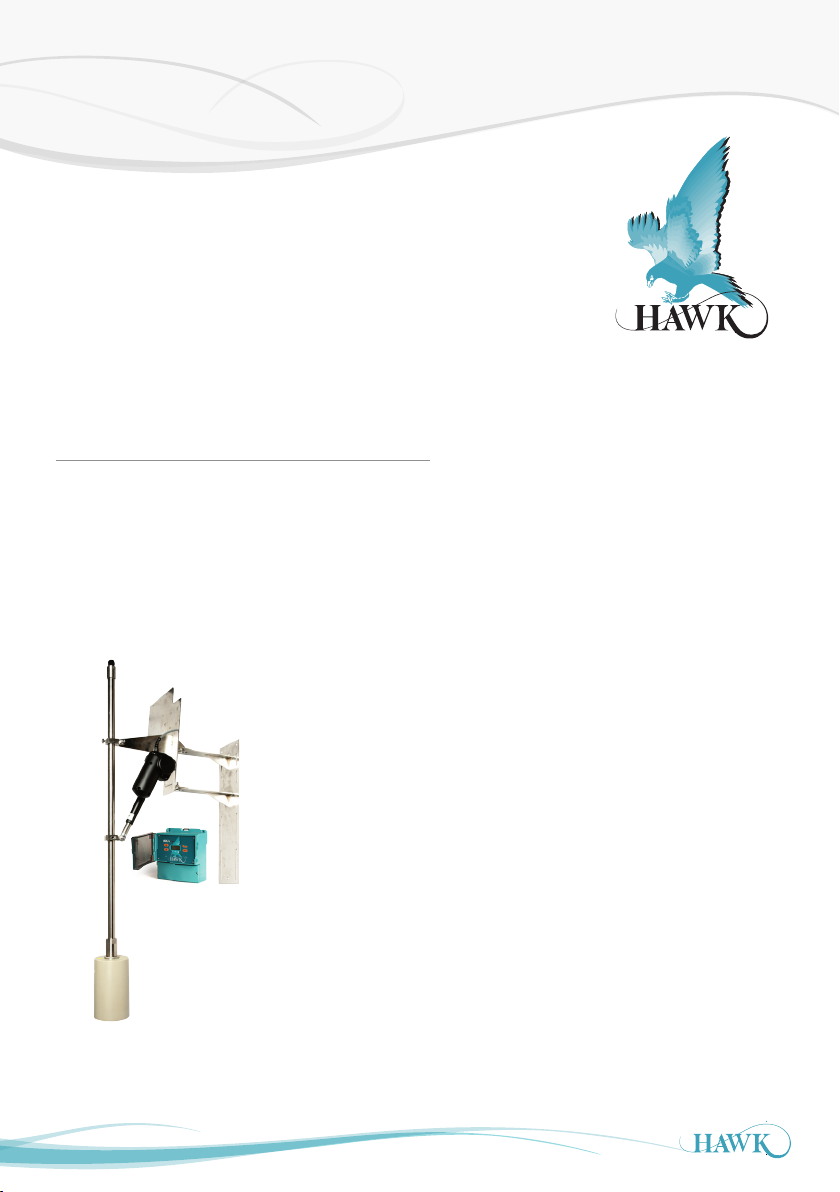
Sultan Sonar Manual Rev 1.0
A Higher Level of Performance
User Manual
ORCA
Sonar System
Sludge and Settling Level Interface Monitoring
For more information, please visit >
www.hawkmeasure.com
Page 2

Table of Contents
ORCA Sonar System
Contents
Overview 3
Principle of Operation 3
Function 3
Benefits 3
Features 3
System Components 4
Auto Scum Cleaner 4
OSIRT Transducer 4
OSIR Amplifier 4
Dimensions 5
OSIR Remote Ampli fier 5
OSIRM ELx* - Mounting Pole 5
OSIRSCE - Impact Pl ate 5
OSIRSCE Impact Plate 6
OSIRT302S4 Transducer 6
OSIRSCA Actuator 6
OSIRT302SH Transducer 6
OSIRSCD Floating Sonar 6
Mounting Bracket 7
Assembly 8
Mounting Bracket / Pole assembly 8
Mounting Bracket / Pole assembly 9
Dimensions & Mounting Connection 10
Impact Plate Mount ing Conn ection 10
Mounting & Hardware Assembly 11
Impact Plate Assembly 11
*A: Impor tant Cab ling Steps to Follow 11
Installation Guide 12
Installation Guide 12
Round Tanks – Cent re Feedwell 12
Rectangular Tanks – End Feed 12
Ball float 12
Impact Plates 12
Wiring 13
Wiring - Remote Transmitter 13
Wiring Extension 13
Actuator Cable Specication 14
Probus PA - Foundation Fieldbus (PA/FF) 15
DeviceNet 16
Probus DP 17
Setup Procedure 18
Powering The Unit 18
Quickset 19
Typical High & Low Level 19
App Type 20
Interface Table 20
Bed Depth
App Type2 21
Interface Table 21
Clarity 21
Output Adjustment 22
Comms Type 23
Comms Type (Menu) 23
Modbus 23
HART 23
Cleaning Menu 24
Cleaning 24
Actuator 24
Setup Procedure 25
Advanced 25
(1)
Gain4 default settings 25
(2)
Gain-Over-Distance bias 25
Relay Actions 26
Operating Diagnostics 27
Operating State 27
Application Calibration 28
How to set up the unit -
Bed Level + Hindered / settling layer measurement 28
Bed Depth
How to set up the unit - Bed Level + Clarity 29
Bed Depth
How to set up the unit - Hindered Layer + Clarity 30
Troubleshooting 31
Unit is measuring i ncorrect Bed or Space 31
PLC indication does not match measurement 31
Some menu options are missing 31
Error Codes 32
Unit Specs & Health Checks 33
ORCA Electric Actuator Troubleshooting 34
Part Numbering 35
Remote Ele ctronics 35
Remote Sonar Transducer 36
Automatic Scum Cleaner 37
Accessories 37
Specications 38
Warranty and Liability 39
20
28
29
2
Page 3

Overview
ORCA Sonar System
Principle of Operation
The ORCA Sonar Series transducer emits a high powered low frequency sonar pulse, which is reflected
from the interface densit y selected. The reflected signal is processed using specially developed software
algorithms that eliminate unwanted densities and stratified layers, allowing measurement of Bed or RAS
levels. It can be calibrated to measure lighter densities such as the hindered / free settling layer & floc or one
of the outputs could be used for a “Clarity” output, similar to a basic turbidity transmitter measuring solids in
suspension. The unit can include two outputs to measure two different interfaces simultaneously.
Function
The ORCA Series Sonar, sludge blanket and interface controller, consists of a microprocessor based
transmitter, with easy menu driven programming via keypad, PC or 3G modem. The ORCA controller works
together with appropriate sonar transducer and transducer cleaning mechanism.
Benets
• Improved ef ficiency and control of the thickener process
• Fully automated plant systems with reliable inter face level monitoring
• Advanced warning of process upset or hydraulic in-balance
• Reduced maintenance with automatic cleaning mechanism warranty (no blades to replace)
• Reduced site operational costs significantly with improved process & extraction control
• Improved health and safety on site (no manual dips required).
Features
• Dual independent analogue outputs to track two
different interfaces, or clarity simultaneously, with
the one sonar sensor
• Easy to use pre-set calibrations to track specic
density interfaces, eg: oc / uff layer, Bed
• Industrial scum cleaning mechanisms that do not
require maintenance
3
• Control room graphics of tanks and interfaces via
GosHawk II
• Wide range of communications: Modbus, HART,
Foundation Fieldbus, DeviceNet, Probus DP and
Probus PA
• 3G remote support capability for calibration,
commissioning or technical back-up
• 3 programmable relays.
Page 4
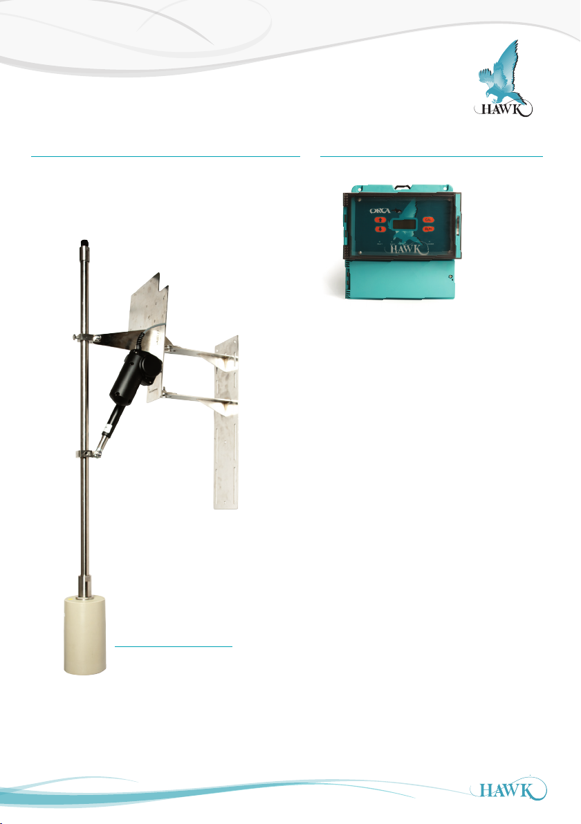
System Components
ORCA Sonar System
Auto Scum Cleaner
OSIRSCA Pictured with Mounting Pole
OSIR Amplier
OSIRT Transducer
4
Page 5
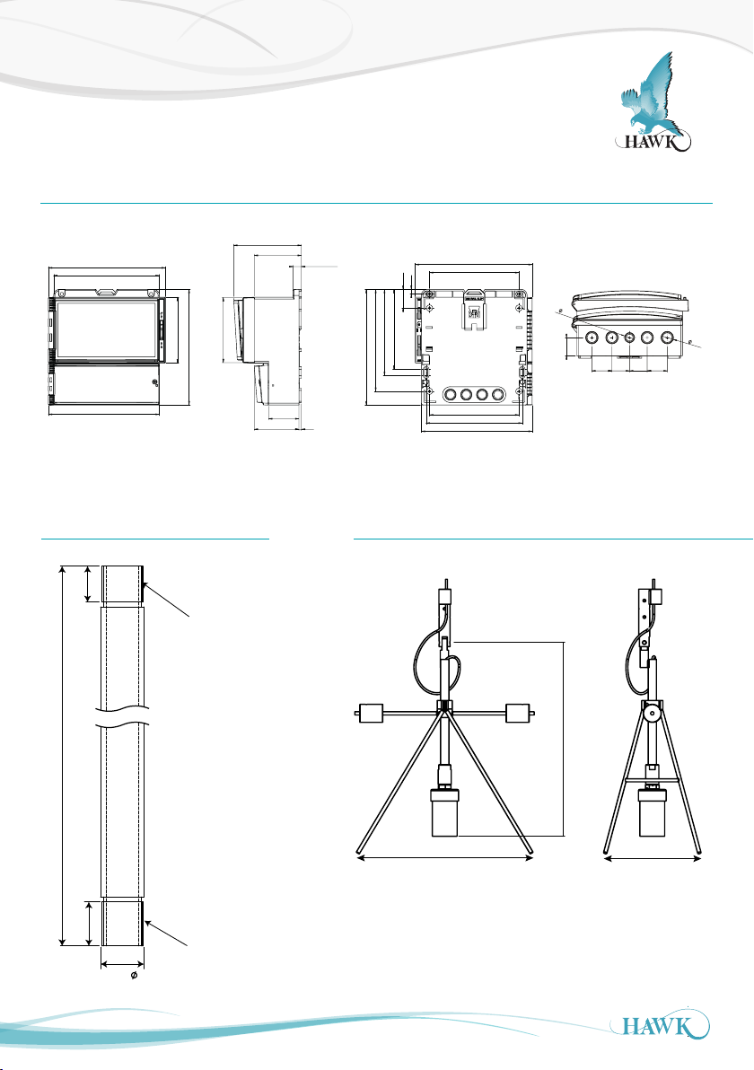
Dimensions
300mm
ORCA Sonar System
OSIR Remote Amplier
192.5 mm (7.6”)
174 mm (6.9”)
108 mm (4.3”)
190 mm (7.5”)
107 mm (4.2”)
111.5 mm (4.4”)
78 mm (3.1”)
14 mm (0.6”)
141.5 mm (5.6”)
167.5 mm (6.6”)
190 mm (7.5”)
7.5 mm (0.3”)
30.7 mm (1.2”)
131.5 mm (5.2”)
192.5 mm (7.6”)
147 mm (5.8”)
1
6
.
2
20
.
30.0
2
33.029.029.033.0
*X mm
22.0
27.0
182.5 mm (7.2”)
26.5
M25 x 1.5 Ext Thd
mates with Cable
Gland Adaptor
HAW_P_ST-SS-EPEC
M25 x 1.5 Ext Thd
mates with Pole Adaptor
HAW_P_ST-SS-TC
50 mm (2”)
74 mm (2.9”)
4 mm (0.2”)
147 mm (5.8”)
158 mm (6.2”)
182.5 mm (7.2”)
OSIRSCE - Impact PlateOSIRMELx* - Mounting Pole
588mm
605mm
300mm
5
Page 6
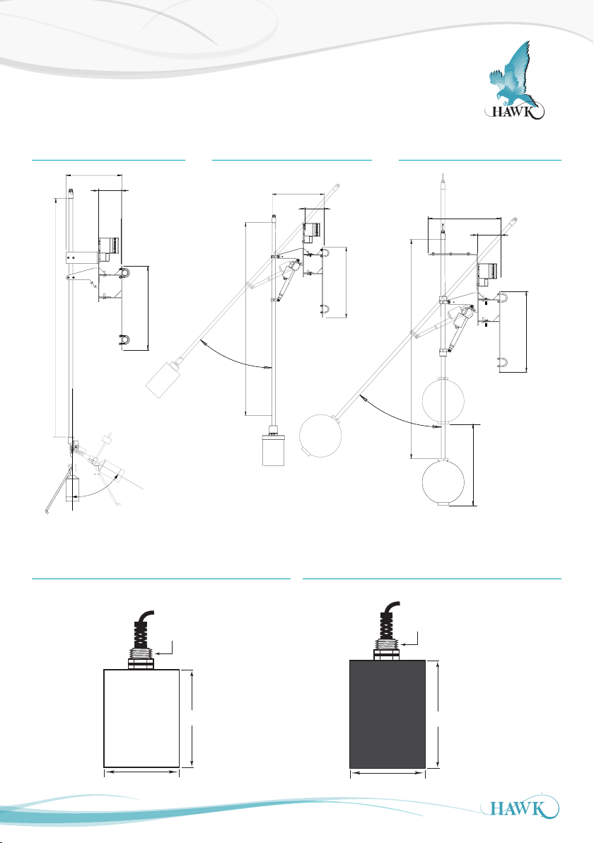
Dimensions
500mm (19.6”)
ORCA Sonar System
OSIRSCE Impact Plate OSIRSCA Actuator OSIRSCD Floating Sonar
X
252mm (9.9”)
650mm (25.6”)
42.5
500mm (19.6”)
252mm (9.9”)
X
o
650mm (25.6”)
42.5
X
o
α°
X = Decent Range
Distance from safety
rail or Bridge may vary
OSIRT302S4 Transducer OSIRT302SH Transducer
605mm (23.8”)
252mm (9.9”)
650mm (25.6”)
X
1" BSP Nipple
200mm (7.9”)
130mm (5.1”)
1" BSP Nipple
230mm (9.0”)
130mm (5.1”)
6
Page 7
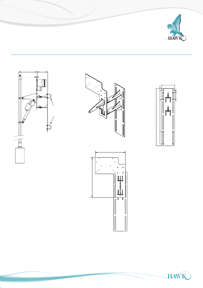
Dimensions
ORCA Sonar System
Mounting Bracket
240.0
252.0
5.0
Rail / Bridge
Mounting U bolts
(A) Base Plate
(A) Base Plate
150.0
20.0
111.5
365.8139.5
650.0
25.0
79.5
330.0
440.0
7
Page 8
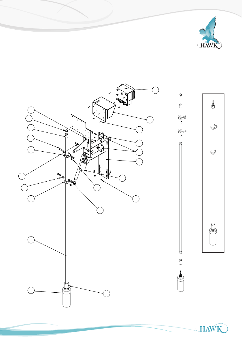
Assembly
11
4
12
10
9
8
3
6
13
7
14
15
18
19
20
1
13
2
5
16
17
ORCA Sonar System
Mounting Bracket / Pole assembly
OSIRSCA pictured
3
17
6
14
7
15
18
8
1
2
11
12
13
4
5
13
20
19
9
10
8
16
Page 9
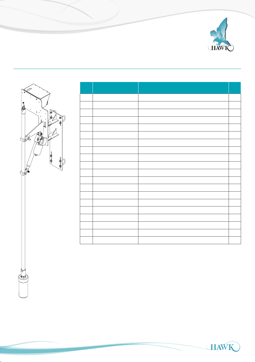
Assembly
ORCA Sonar System
Mounting Bracket / Pole assembly
Item
Part Number Description Qty
No.
1 OSIRxxx ORCA Transmitter 1
2 SUNHOOD Stainless Steel Sunhood 1
3 SA- SS-A AFB Stainless Steel Front Bracket 1
4 SA-SS -AARB Stainless Steel Rear Bracket 1
5 LAUS061196E Actuator Actuator (only with OSIRSCA/OSIRSCD) 1
6 ST-SS-EPEC Pole to Cab le Gland A daptor wi th M16 cable g land 1
7 ST-APC-26.8-IN T SS Internal Pipe Clamp 1
8 ST-APC-26.8-E XT SS External Pipe Clamp 1
9 ST-SS-EP Mounting Pole 1
10 OSIRTxxxxxxxx Sonar Transducer 1
11 ZPP-M5X 20MM M5x20 Phillips Pan Head 8
12 U-BOLT 50mm x 8DIA U -Bo lt with nuts and wash ers 4
13 BOL-M10x15SS M10 x 15mm SS Bo lt 4
14 BOL-M10x50SS M10 x 50 mm SS Bolt with wash er & nyloc nu t 1
15 BOL-M10x40SS M10 x 40 mm SS Bolt w ith washer & nyloc nut 2
16 ST- SS -TC Sonar Pole Adaptor 1
17 G LA -M16 M16 Ca ble glan d IP68 wi th washe r 1
18 Washer-M10 M10 washer for M10x40mm & M10x5 0mm SS Bolt 6
19 Nut-M10 M10 nut for M10x40mm & M10x5 0mm SS Bo lt 5
20 Nut- M8 M8 nyloc n ut for 50 mm U-b olt 8
9
Page 10
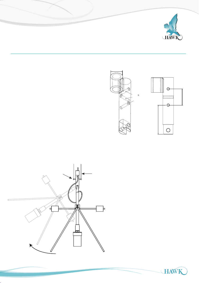
Dimensions & Mounting Connection
ORCA Sonar System
Impact Plate Mounting Connection
The top of the Impact Plate has 3 x 7mm bolt holes
which can be secured to an angle iron or equivalent
bracket. There is also a M25 (1.5”) threaded
connection for a mounting pole connection. The
Impact Plate is designed to swing parallel with the
counter weights. The surface sweeper must come
in contact with the legs of the Impact Plate which
swings the bracket lif ting the transducer out of the
liquid. When the sweeper has cleared, it will drop
back in and use the counter weights to re-center. The
force of the movement will clear the sensor face of
any build up
Bolt
Impact Plate Connection Point
M25 x 1.5 INT
THD THRU
ISOVIEW FOR
REFERENCE ONLY
Angle iron or equivalent
7.00
(0.79”)
×3
50mm (1.97”)
90mm (3.54”)
Swing
10
Page 11
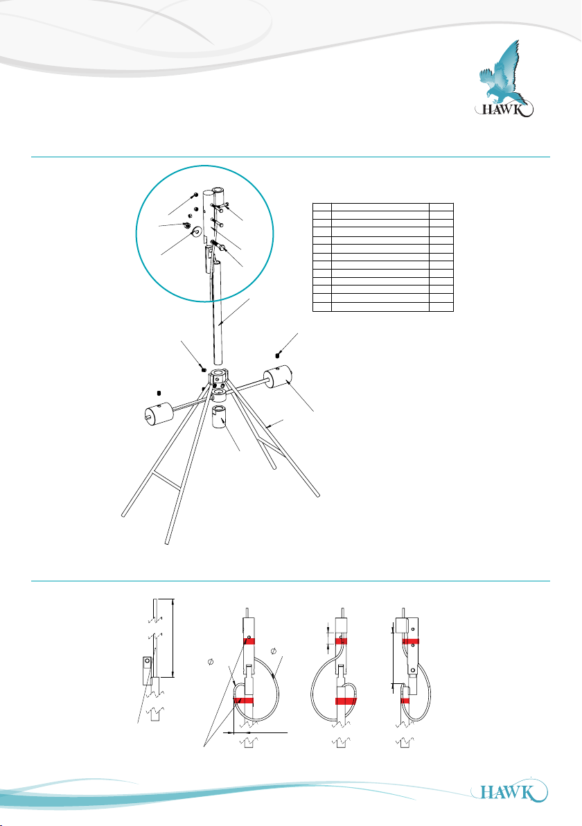
Mounting & Hardware Assembly
ORCA Sonar System
Impact Plate Assembly
*A
10
11
12
6
5
7
4
9
2
*A: Important Cabling Steps to Follow
1
No. Description
1
Impact Plate Dual Direction
Sonar Pole Adaptor
2
3
Impact Plate Counter Balance
4
Sonar Male Clevis Assembly
Sonar Female Clevis Assembly
5
6
M6×45 Stainless Steel Bolt
M10×40 Stainless Steel Bolt
7
M10×12 Stainless Steel Set Screw
8
M10×20 Stainless Steel Set Screw
9
M6 Stainless Steel Nut
10
M10 Stainless Steel Nyloc Nut
11
M10 Stainless Steel Washer
12
8
3
QTY.
1
1
1
1
1
3
1
4
2
3
1
1
mm03
Front
30mm
160mm
Back
170mm
Right
Allow 550mm loose
cable
to perform the
looping of the cable
550mm
Use electrical tape to
hold cable in place
60mm
11
Page 12
Installation Guide
1/2 Submerged
ORCA Sonar System
Installation Guide
ORCA Transmitter – Mounting Requirements
Select a suitable mounting position, preferably not in
direct sunlight. If necessary utilize a sunshade.
Observe the maximum and minimum temperature
specification.
Do not mount the sonar transmitter near high sources
of EMF, such as motor starters, variable speed drives
or 3 phase cables. Avoid mounting in high vibration
areas, or use rubber absorption mounts.
Be careful when removing the cable and compression
glands.
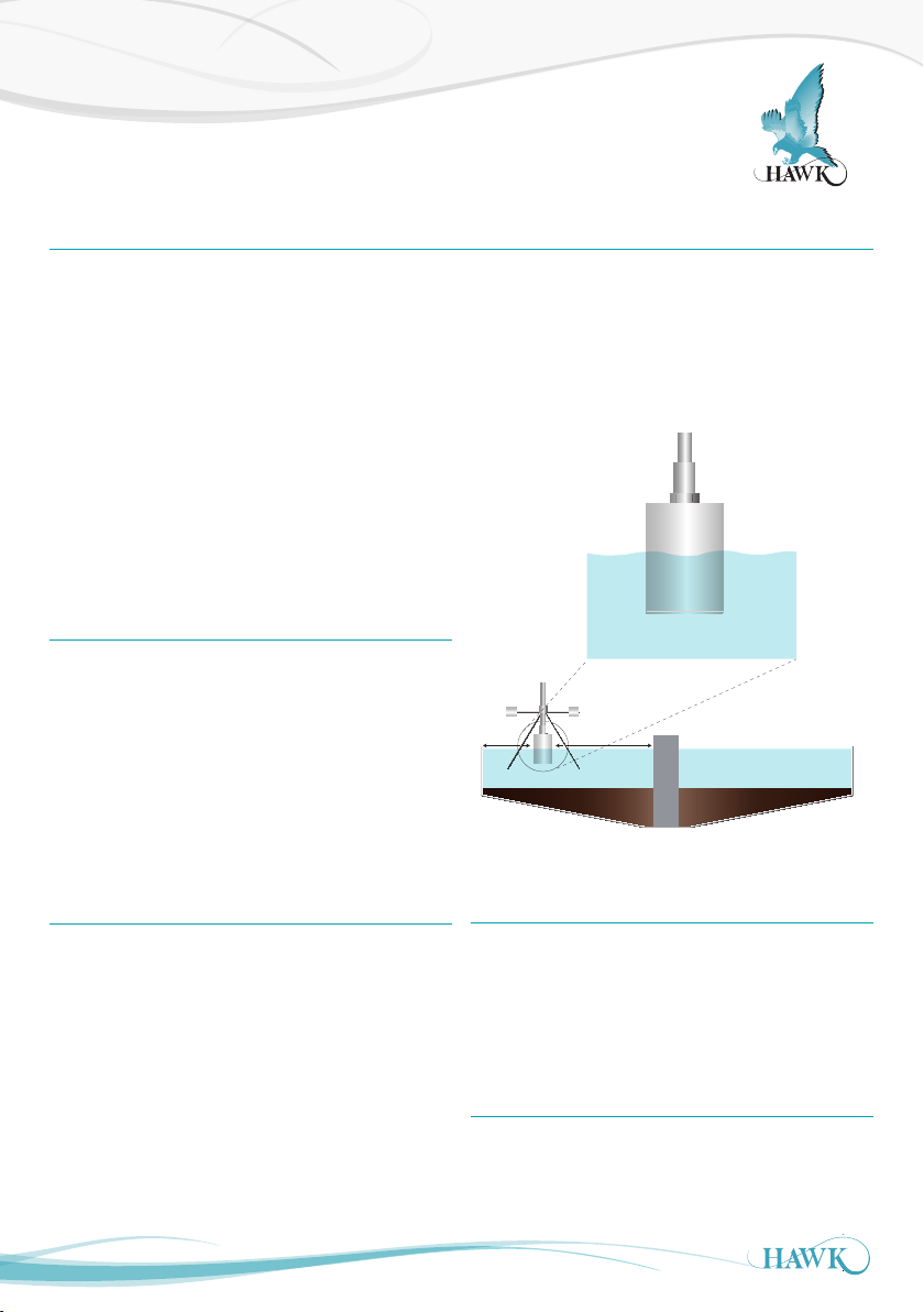
Round Tanks – Centre Feedwell
Mount the sonar transducer and cleaning mechanism,
approximately one third radius between the outside
tank wall and the feedwell. This is the same whether it
is a moving or f ixed bridge installation.
Do not mount near high infeed turbulence.
Choose a site installation where the infeed is least
disturbed.
Rectangular Tanks – End Feed
Sonar Transducer – Mounting Requirements
The transducer should be half submerged in the liquid
and the transducer face must always be submerged.
Wrap cable entry and lower connection cable with
Teflon tape
1/3 Radius
Ball oat
Mount the sonar transducer and cleaning mechanism
away from high infeed turbulence. A clearance of
700mm from the side wall.
Do not mount directly over scraper, chain
mechanisms. Choose a site installation where the
infeed is least disturbed.
12
Mount the floating sonar transducer and cleaning
mechanism as close as practicable to the launders.
Mount at least 1.00 metres from side walls. Ensure
alignment guides are installed on the mounting
bracket for decanter ranges above 500mm.
Impact Plates
Leave an extra 2 turns of cable where the transducer
connects to the actuator to minimise stress and wear
on the cable (see Impact Plate Assembly).
Page 13
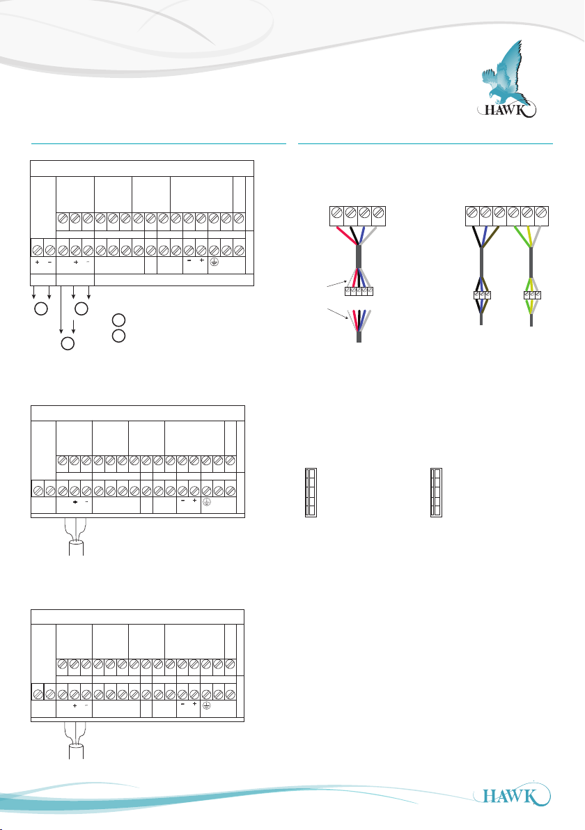
Wiring
Driving 4-20mA from ORCA to user PLC
Modulating 4-20mA from PLC input
1
2
1
2
+
+
RELAY 1 RELAY 2 RELAY 3 ACTUATOR
NC
COMNONC
COMNONC
COMNOBLK
BLU
BRN
GRN
YEL
SHLD
ANALOG1 TRANSDUCER
COMMS DC-IN AC-IN
RED
BLK
BLU
WHT
Test
B
A
N
L1
4-20mA
DC IN
AC IN
Is
BOTTOM TOP
SONAR 234 REMOTE TRANSMITTER
Output 1Output 2
Driving 4-20mA from ORCA to user PLC
Modulating 4-20mA from PLC input
1
2
1
2
+
+
RELAY 1 RELAY 2 RELAY 3 ACTUATOR
NC
COMNONC
COMNONC
COMNOBLK
BLU
BRN
GRN
YEL
SHLD
ANALOG1 TRANSDUCER
COMMS DC-IN AC-IN
RED
BLK
BLU
WHT
Test
B
A
N
L1
4-20mA
DC IN
AC IN
Is
+
4-20mA
BOTTOM TOP
ANALOG2
SONAR 234 REMOTE TRANSMITTER
1
Output 1Output 2
RED
BLK
BLU
WHT
BLK
BLU
BRN
GRN
YEL
SHLD
TRANSDUCER ACTUATOR
Junction Box for
wiring extension
RED
BLK
BLU
WHT
Shield
Separate
cable
shielding
Separate
potentiomer
wires from
power wires
V+
CAN_H
Top
B (in)
A (in)
Top
Driving 4-20mA from ORCA to user PLC
Modulating 4-20mA from PLC input
1
2
1
2
+
+
RELAY 1 RELAY 2 RELAY 3 ACTUATOR
NC
COMNONC
COMNONC
COMNOBLK
BLU
BRN
GRN
YEL
SHLD
ANALOG1 TRANSDUCER
COMMS DC-IN AC-IN
RED
BLK
BLU
WHT
Test
B
A
N
L1
4-20mA
DC IN
AC IN
Is
+
4-20mA
BOTTOM TOP
ANALOG2
SONAR 234 REMOTE TRANSMITTER
1
Output 1Output 2
RED
BLK
BLU
WHT
BLK
BLU
BRN
GRN
YEL
SHLD
TRANSDUCER ACTUATOR
Junction Box for
wiring extension
RED
BLK
BLU
WHT
Shield
Separate
cable
shielding
Separate
potentiomer
wires from
power wires
ORCA Sonar System
Wiring - Remote Transmitter Wiring Extension
SONAR 234 REMOTE TRANSMITTER
RELAY 1 RELAY 2 RELAY 3 ACTUATOR
NC
COMNONC
COMNONC
COMNOBLK
BLU
ANALOG2
ANALOG1 TRANSDUCER
+
Is
4-20mA
4-20mA
Output 1Output 2
1
2
+
1
COMMS DC-IN AC-IN
A
RED
BLK
1
2
B
BLU
WHT
DC IN
Test
Modulating 4-20mA from PLC input
Driving 4-20mA from ORCA to user PLC
Foundation Fieldbus
SONAR 234 REMOTE TRANSMITTER
RELAY 1 RELAY 2 RELAY 3 ACTUATOR
Prof ib us PA
NC
COMNONC
FIELDBUS TRANSDUCER COMMS DC-IN AC-IN
ENC
GND
FIELDBUS
RELAY 1 RELAY 2 RELAY 3 ACTUATOR
NC
PROFIBUS TRANSDUCER COMMS DC-IN AC-IN
ENC
GND
+
RED
SONAR 234 REMOTE TRANSMITTER
COMNONC
+
RED
COMNONC
COMNOBLK
BLK
BLU
COMNONC
BLK
BLU
A
B
WHT
Test
COMNOBLK
A
B
WHT
Test
BLU
DC IN
BLU
DC IN
BRN
+
BRN
+
BRN
GRN
+
GRN
AC IN
GRN
AC IN
AC IN
YEL
N
YEL
N
YEL
N
SHLD
L1
SHLD
L1
SHLD
L1
BOTTOM TOP
BOTTOM TOP
BOTTOM TOP
TRANSDUCER ACTUATOR
BLU
BRN
Separate
potentiomer
wires from
power wires
GRN
YEL
Separate
cable
shielding
RED
Shield
BLK
RED
BLU
BLK
BLU
WHT
Junction Box for
wiring extension
WHT
BLK
DeviceNet / Profibus DP
Terminal plug located right hand side of main terminal
board.
Top
V+
CAN_H
SHEILD
CAN_L
V-
DeviceNet Profibus DP
Top
B (in)
A (in)
SHEILD
B (out)
A (out)
SHLD
13
PROFIBUS
Page 14
Actuator Cable Specication
ORCA Sonar System
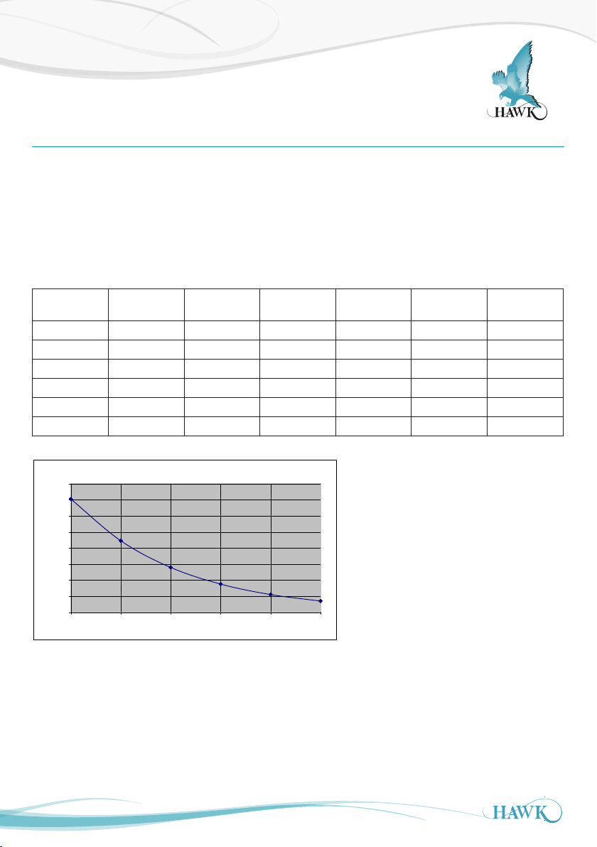
Actuator Cable Specication
Note 1: Calculations based on:
4.0 Amps max actuator current and;
4.0 Volts drop across max cable length ( 2 wires)
Note 1: Note 2: Maximum terminal capacity is 1.5mm, which limits 16AWG cable to35m.
Note 3: For long c able runs, use 16 AWG to local junction box, then extend using 10 -14 AWG.
Note 4: Also required: 3-wire cable for feedback potentiometer, 0.5mm - 1.0mm.
Gauge
AWG
Nom OD
mm
Resist
Ohm/1000ft
Resist
Ohm/m
Loss
V/m
Max Res
Ohm
10 2.9201 0.80 0.0035 0.028 1.00 141.1
12 2.4401 0.71 0.0056 0.045 1.00 89.1
14 1.9302 0.73 0.0090 0.072 1.00 55.8
16 1.5204 0.35 0.0143 0.114 1.00 35.0
18 1.2206 0.92 0.0227 0.182 1.00 22.0
20 0.965 0.90 0.0358 0.286 1.00 14.0
160.0
140.0
120.0
100.0
80.0
60.0
Max Distance (m)
40.0
20.0
0.0
10 12 14 16 18 20
Actuator Motor Cable Guide
Wire Gauge (AWG)
Max Dist
m
14
Page 15

Probus PA - Foundation Fieldbus (PA/FF)
ORCA Sonar System
Probus PA - Foundation Fieldbus (PA/FF)
See dedicated manual for Profibus PA and FF available from http://www.hawkmeausure.com
15
Page 16
DeviceNet
ORCA Sonar System
DeviceNet
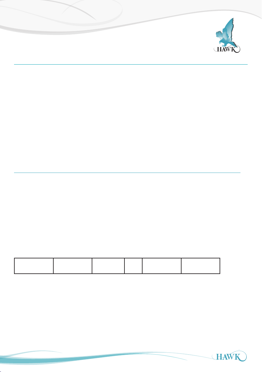
Set the BaudRate and the DeviceNet Address in
Sultan
Factory defaults of baudrate and FBusAdds are
125kbps and 63 in a Sultan unit with DeviceNet
CommType. To modify these values follow the
instructions below.
1. Go to the Output Adjustment menu
2. Use the Up and Down push buttons to reach the
CommType parameter
3. Make sure that the CommType is set to DeviceNet
4. Press the CAL button twice. If you see DeviceID do
not modify this parameter.
Output Data
Profibus DP and DeviceNet now transmit 18 bytes/9
words, description of the words is as follows (For
firmware version 5.54 and above)
1. Displayed Distance
(Space Distance is the Primary Variable)
2. Percentage (Percent of Range)
3. Hi Level (Upper Range)
5. Use the Down push button to reach the BaudRate
parameter
6. The default value for the BaudRate is 125kpbs.
Press CAL button and use the Up and Down push
buttons to modify this value
7. Press CAL button when finished
8. Use the Down push button to reach the FBusAdds.
The default value of the Fieldbus Address is 63.
Press CAL button and use the Up and Down push
buttons to modify this value
9. Press CAL button again when finished
4. Low Level (Lower Range)
5. Status Flags
6. Displayed Distance2 (Second Variable)
7. Percentage2 (Second Percent of Range)
8. Displayed Distance3 (Third Variable)+
9. Percentage3 (Third Percent of Range)+
Faile d ~~~~~~ Search 0 Echo Cfm : 1 =
True, 0 = False
Bit F Bit E Bit 3 Bit 1 Bit 0
Bit0 = Echo was received inside the span.
Bit1 = Echo is Confirmed.
Bit3 = Searching is searching for an Echo.
BitF = Unit has Failed to detect an Echo.
16
+Only used for ORCA Sonar Clarity output.
Echo R : 1 =
True, 0 = False
Page 17
Probus DP
ORCA Sonar System
Probus DP
Set the Prof ibus Address in Sultan
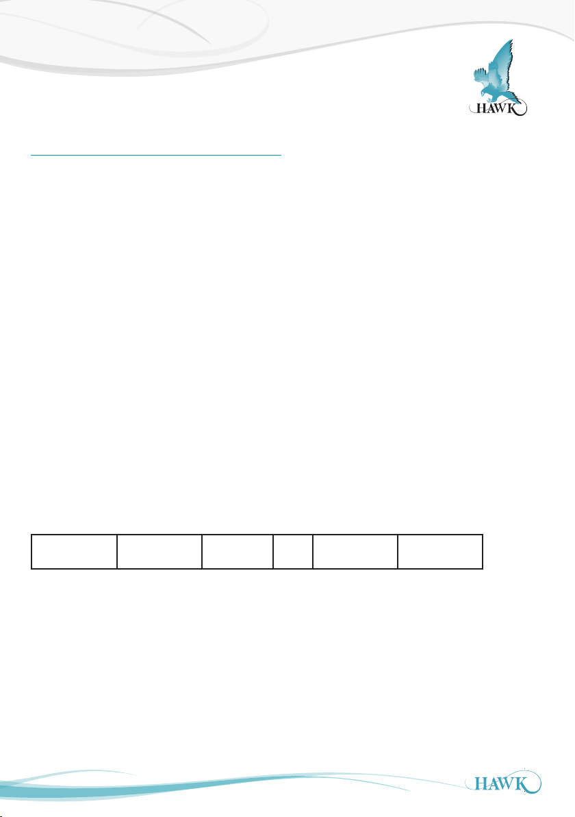
Factory defaults of FBusAdds is 126 in a Sultan unit
with Profibus CommType. To modify this value follow
the instruction below:
1. Go to the Output Adj menu
2. Use the Up and Down push buttons to reach the
CommType parameter
3. Make sure that the CommType is set to
Profibus DP
Output Data
Profibus/DeviceNet now transmit 18 bytes/9 words, description of the words is as follows (For f irmware
version 5.54 and above).
1. Displayed Distance
(Space Distance is the Primary Variable)
2. Percentage (Percent of Range)
3. Hi Level (Upper Range)
4. Low Level (Lower Range)
Faile d ~~~~~~ Search 0 Echo Cfm : 1 =
4. Press the CAL button twice - If you see DeviceID
do not modify this parameter
6. Use the Down push button to reach the BaudRate
parameter. Note this cannot be modified
8. Use the Down push button to reach the FBusAdds.
The default value of the Fieldbus Address is 126.
Press CAL button and use the Up and Down push
buttons to modify this value
9. Press CAL button again when finish.
5. Status Flags
6. Displayed Distance2 (Second Variable)
7. Percentage2 (Second Percent of Range)
8. Displayed Distance3 (Third Variable)+
9. Percentage3 (Third Percent of Range)+
Echo R : 1 =
True, 0 = False
True, 0 = False
Bit F Bit E Bit 3 Bit 1 Bit 0
Bit0 = Echo was received inside the span.
Bit1 = Echo is Confirmed.
Bit3 = Searching is searching for an Echo.
BitF = Unit has Failed to detect an Echo.
+Only used for ORCA Sonar Clarity output.
17
Page 18
Setup Procedure
Advanced
ORCA Sonar System
Powering The Unit
When power is applied the unit will start up automatic ally. It will scroll through its boot diagnostics and display
the serial numbers, software version and model types for the amplifier and transducer
The unit will display its default operating screen depending on the App Type selected (default: Bed) on the
top line and a distance or % on the bottom line. The distance will be the programmed display mode (Default:
Level).
The unit will re-scan for the measurement whenever it is powered up.
The sensor face must be submerged in liquid in order to operate correctly.
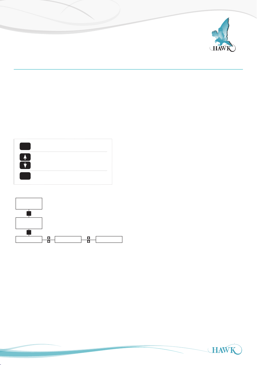
CAL for select / proceed / edit
CAL
Arrows to scroll / adjust
RUN
RUN to re-active unit
Bed
CAL
Unlock 0
CAL
Quickset
Amplif ier /
Application
settings
18
Operating Diagnostic Display
Unlock Code (default 0)
Output Adj Advanced*
Comms / Output
Settings
Transducer
settings.
*Do not adjust Advanced settings without expert knowledge
Main Menus
Page 19
Setup Procedure
1/2 Submerged
ORCA Sonar System
Quickset
The Quickset menu contains the basic parameters required to get the unit up and running.
It is one of the three main menu options in the internal software.
Parameter Description Options
Unit Adjust displayed measurement unit Inches Feet Meters Centimeters
Ap p Type Select Application Parameters for Output 1 See Unit Setup: 'App Type'
Ap p Type 2 Select Application Parameters for Output 2 See Unit Setup: 'App Type2'
Failsafe Set failsafe output & timer
DispMode Set LCD measurement display mode Level Level% Space
Offset Add offset distance to output Adjustable
Amp Reset Restore A mplifier settings to factory default Yes / No
20mA 4mA LastKnown 3.80mA 3.50mA
20.20mA
Typical High & Low Level
Blanking /
non-measured
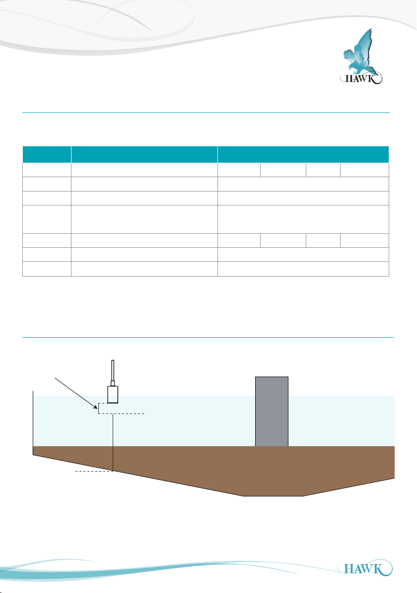
Typical installation - Set ‘Low Level’ (4mA) to be the distance from the transducer face to the bottom of the
tank. High Level should be 0.600m for most accurate and reliable measurement.
19
zone
High Level
20mA
0.600m
Low Level
4mA
X.xxm
Page 20
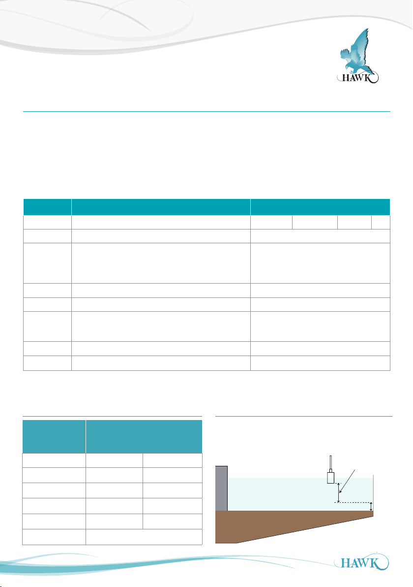
Setup Procedure
ORCA Sonar System
App Ty p e
App Type is the first output and should be considered the primary measurement. If monitoring Bed level this
should be selected here. App Type has three pre-set application types.
• Bed (dense/heavy blanket layer).
• RAS (return activated sludge)
• Floc (Flocculent /hindered settling layer).
Parameter Description Options
Ap p Type Set display readout Bed RAS Floc
Density Select inter face to be measured See Interface Table below
• Manually fine tune sensor sensitivity
Calibrat
Lo Level Set Lo Level measurement point (4mA) Adjustable
Hi Level Set Lo Level measurement point (20mA) Adjustable
Bed Depth
Fill Rate* Set potential filling rate for primary measurement Adjustable (units per hour)
Empty Rate* Set potential emptying rate for primary measurement Adjustable (units per hour)
*For most applications the unit is pre-calibrated with appropriate tracking speeds.
You will not need to adjust these settings.
Int e r fac e Ta b l e
• Press CAL to fire a test pulse which will
return the depth measurement.
Set maximum expected Bed Depth - see Bed Depth
(1)
for further information
Bed Depth
Higher value for lighter densities, lower
value for heavier densities.
(1)
Adjustable in depth (measured from
Sensor face down)
(1)
Density
Selected (g/l)
0.1 - 0.6 Lighter layers
0.6 - 1.2 Hindered Layer Settling Layer
1.2 - 3.0 RAS
3.0 - 6.0 RAS Bed
6.0 -1 0.0 Bed
10+ Bed / Heav y Sludge
20
Typical Applications
Bed Depth should be programmed to 1m (3ft) higher
than the application expected maximum depth
Bed Depth
(Max Bed + 1m (3ft)
Max Bed
1m
Page 21
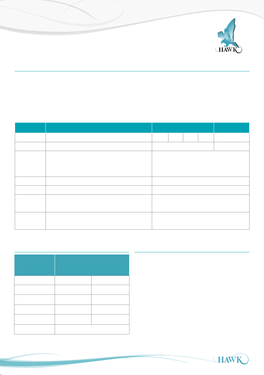
Setup Procedure
ORCA Sonar System
App Ty p e2
App Type is the second output and should be considered the secondary measurement. This output is sampled and
updated at programmed inter vals
• Bed (dense/ heavy blanket layer).
• RAS (return activated sludge)
• Floc (Flocculent/hindered settling layer).
• Clarit y (indication of signal lost due to liquid conditions, 0% poor conditions, 100% clean conditions)
Parameter Description Options
Ap p Type 2 Set display readout for secondary measurement Off Bed Ras
Density Select inter face to be measured See Interface Table below
• Manually fine tune sensor sensitivity
Calibrat
Lo Level2 Set Lo Level measurement point (4mA) Adjustable
Hi Level2 Set Lo Level measurement point (20mA) Adjustable
SmplRate
Damping2 Adjust 2nd output response time / smoothness
** See 'Clarity' for important information
• Press CAL to fire a test pulse which will
return the depth measurement.
Set the time between measurement samples taken
for the App Type2
Higher value for lighter densities, lower value
for heavier densities.
Adjustable (minutes)
Value in pulses, approximately 2 pulse per
second
Floc Clarity**
Int e r fac e Ta b l e
Density
Selected (g/l)
0.1 - 0.6 Lighter layers
0.6 - 1.2 Hindered Layer Settling Layer
1.2 - 3.0 RAS
3.0 - 6.0 RAS Bed
6.0 - 10.0 Bed
10+ Bed / Heav y Sludge
21
Typical Applications
Clarity
Clarity is a representation of how c lear the liquid is
between the inter face measured by App Type (output 1)
and the transducer face.
The unit monitors the number and quality of return
echoes and uses an algorithm to conver t this to a
percentage. The percentage is a rolling average of
approximately 5 minutes of measurement.
Page 22
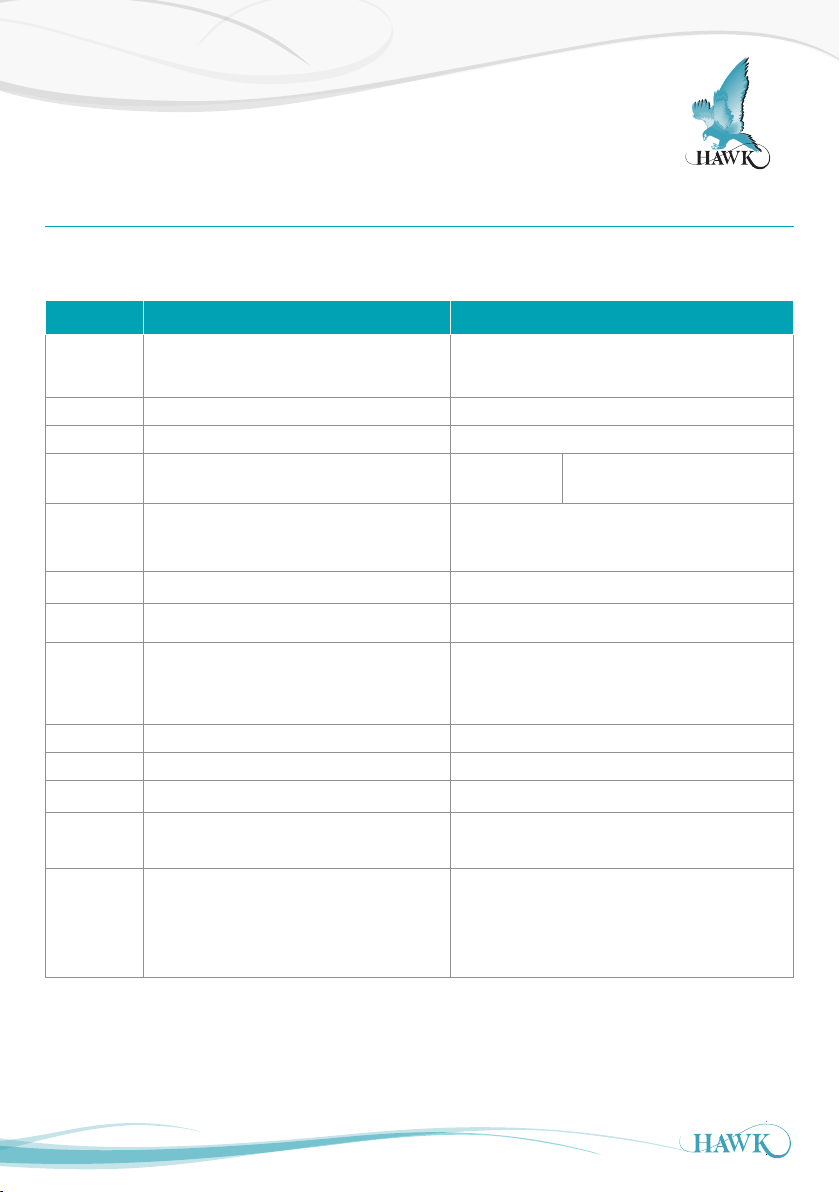
Setup Procedure
ORCA Sonar System
Output Adjustment
The Output Adj menu contains parameter s related to adjusting analogue, switch & communic ation protocol relayed
settings.
Parameter Description Options
FillDamp
EmtyDamp
4mA Adj Fine tune the 4mA output current Adjustable
20mA Adj Fine tune the 20mA output current Adjustable
Analog Invert analogue from 4-20mA to 20- 4mA 4-20mA 20 -4mA
Simulate
4mA Adj2 Fine tune the 4mA output 2 current Adjustable
20mA Adj2 Fine tune the 20mA output2 current Adjustable
Comm Type
RlyMo d 1-3 Configure Relay actions See 'Relay Actions' section
Cleaning Set auto cleaner parameters See 'Cleaning' section
Bk Light Turn on/off LCD backlight On/Off
DispChar
V In Chk
Adjust first output response time /
smoothness
A simulated distance reading is transmitted
as analogue (distance measured from sensor
face)
• Adjust communication protocol set tings
• Analogue and Switch models include
Modbus as standard
Switch display from 12 character to 8
character (older units)
When active the unit will switch to failsafe
mode if input voltage drops below required
power. When not active unit will display ‘Input
Voltage too low' on the display.
Value in pulses, approximately 2 pulse per second
Adjustable
See 'Comms Type' section
12 digit / 8 digit
On / Off
22
Page 23
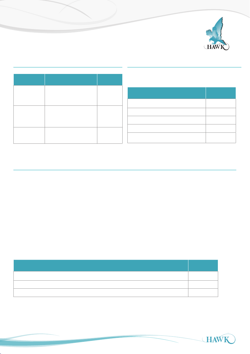
Comms Type
ORCA Sonar System
Comms Type (Menu)
Sub-Menu Description Options
DeviceID
FBusAdd
BaudRate
Adjust unit device ID for
Modbus, HART
Adjust unit Device ID
for FF/PA, DeviceNet,
Profibus DP
Adjust comms network
speed
1-255
1-255
Comms
dependant
HART
Command Number 3
Current and dynamic variables
Description Byte No.
Cur rent (mA) 0-3
PV1 Unit (App Type1) 4
PV1 Measurement (App Type 1) 5-8
SV unit (App Type 2) 9
SV measurement (App Type 2) 10 -13
Modbus
Protocol: Modbus RTU (2 wire)
Speed: 19200 Baud
Data bits: 8
Parity: None
Stop Bits: 1
HAWK Sultan series units act as ‘slave’ devices on a Modbus network. Units are shipped from the factor y with a
default Modbus address of 1. The Modbus address of any unit c an be changed individually if units are to be connected
in a multi-drop network. Each address number must only be used once on any network (possible addresses are
1-255).
Primary Measurement Modbus Registers
Description Address
App Type (Output 1) measured distance (from sensor face to measured level), mm 40125
App Type2 (Output 2) measured distance (from sensor face to measured level), mm 4 0 118
Clarity (%) 40 117
Note: Comms option 'X' and 'Y' includes Modbus as standard.
23
Page 24
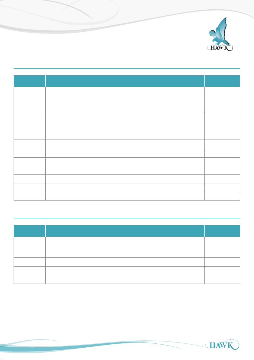
Cleaning Menu
ORCA Sonar System
Cleaning
Sub-Menu Description Options
Intvl
Spry
Solenoid Uses Relay 3 to drive an external solenoid (used for pneumatic actuator control) Selectable
Brush Uses Relay 3 to drive an external solenoid (used for wiper brush control) Selectable
Actuator
Off Disables Cleaner function Selectable
Actua In Manually trigger Actuator to 'in' (home) position* Selectable
Actua Out Manually trigger Actuator to 'out' (extended) position* Selectable
Keeps the ac tuator swing extended for the selected time inter val before
retracting to normal position
Uses Relay 3 to activate an ex ternal system (such as a spray cleaner) for the
selected time. The actuator swing will be at full extension for this selected time.
Selects Actuator auto cleaning function (default cleaning option). Actuator will
extend and retract based on programmed timer.
6 minutes
3 minutes
1 minutes
90 seconds
60 seconds
30 seconds
See 'Actuator'
Actuator
Sub-Menu Description Options
Act Max
Act Min
Cycle Set timer in minutes between Actuator swings Adjustable
VoltCutOff
Adjust the default swing position (Max) and Home position (Min Adjuatable (mm)
Set minimum voltage present before Actuator action is canc elled and error
message ActuatorErr or ActuatorVsErr is displayed on screen
Default 14V
*If testing with these parameters you must follow this sequence for the Actuator to function correctly
• Select 'Actua Out'
• Select 'Actua In'
• Select 'Actuator'
The Actuator must be returned to 'In' mode before activating the auto cleaning function for standard operation.
24
Page 25
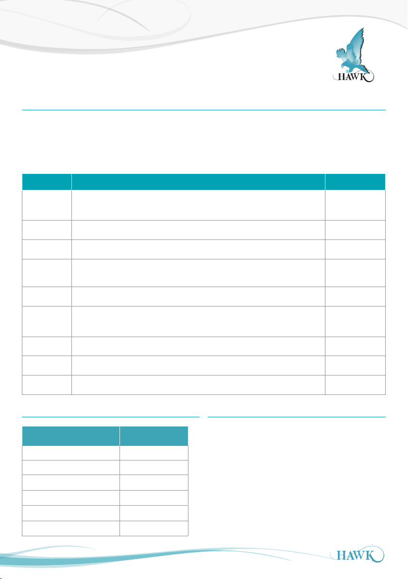
Setup Procedure
ORCA Sonar System
Advanced
The Advanced menu contains parameters for Gain control, manually adjustment of speed of sound, of fset and
restoring the amplifier and transducer to their default state.
These settings typically do not require adjustment unless there are special circumstances. Do not adjust
Advanced settings without expert knowledge or consulting your local representation.
Parameter Description Options
Gain4
GainStep3 Adjustment of sensitivity for DistStep3 zone. Adjustable
DistStep3 Depth of zone measured from the sensor face for non-variable GainStep3. Adjustable
Primary sensitivity adjustment. This value is automatically
selected Interface range in Quickset. Higher values for lighter densities.
(1)
set by the
Adjustable
SlopeInc
Threshold Minimum echo size which the unit will accept as a valid echo Adjustable
EmptyDist
Tem p Trim Create manual measurement offset for a specific temperature. Adjustable
Di s t Trim Create manual measurement offset for a specific distance. Adjustable
Velocity Adjusts the internal speed of sound calculation. Adjustable
(1)
Gain4 default settings
Increase or decrease Gain-Over-Distance bias
Unit will not consider any echoes beyond this distance valid.
This is automatically calculated by the ‘Low Level’ parameter.
Inter face Selected (g/l) Default Value
0.1 - 0.6 24.9%
0.6-1.2 14.9%
1.2-3.0 10.0%
3.0-6.0 4.9%
6.0-10.0 2.0%
10+ 1.1%
(2)
(2)
Gain- Over-Distance bias
The ORCA system uses automatic Gain control
to enhance signal tracking during difficult process
conditions. Increasing SlopeInc% from 1.5% to 2%-
4% will assist the unit to place emphasis on deeper
measurement (bed level). If the unit is locking to a
higher interface during sliming or difficult conditions
try increasing this value. Do not exceed 4%. See
'Troubleshooting' for more information.
Adjustable
(default 1.5%)
Adjustable
25
Page 26
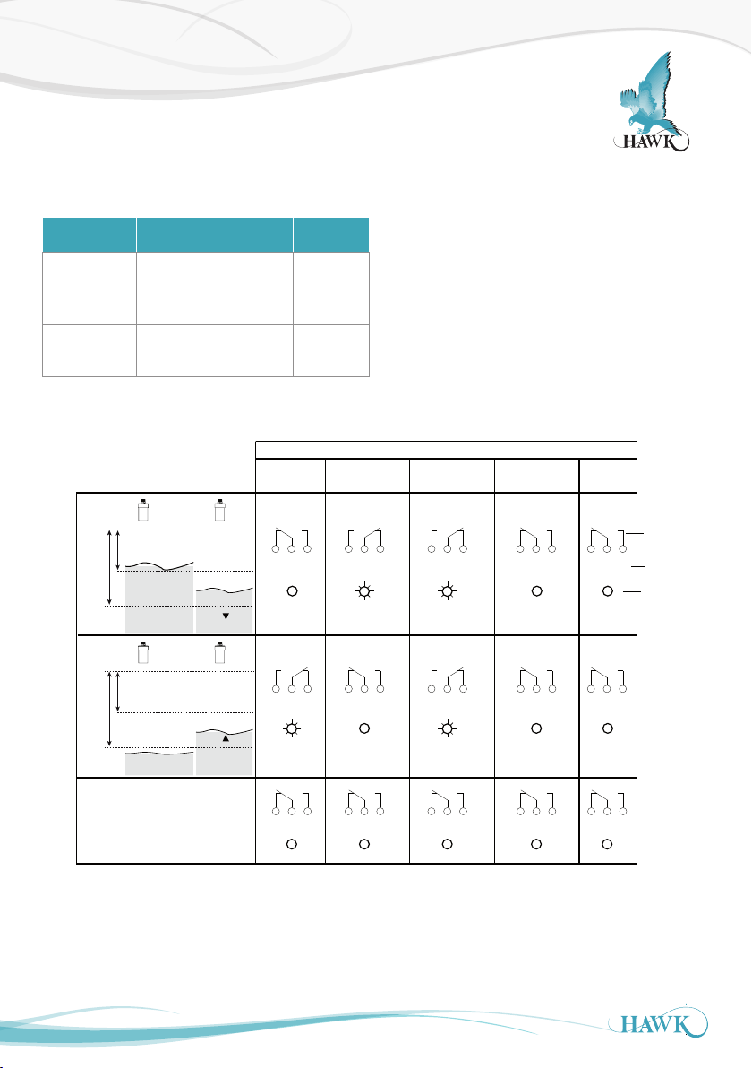
Relay Actions
ORCA Sonar System
Relay Actions
Sub-Menu Description Options
Rly L1 1- 5
RlyL2 1-5
Adjust Relay switch point
(L1 must be < L2)
Adjust Relay switch point
(L2 must be > L1)
L1
Above L1 or
State 1
L2
HIGH LEVEL or
L1
Below L2 or
L2
State 2
between L1 and
L2 after passing
above L1.
FALLING LEVEL
between L1 and
L2 after passing
below L2.
Energise
EN
NC NOCOM
Adjustable
Adjustable
DeEnergise
DEN
NC NOCOM
NC NOCOM
Set Relay Parameters in Output Adjustment menu
The two relay levels are RlyL1 and RlyL2
The display will show RlyL1 1, the last 1 indicated the
Relay number (eg 1 to 5)
L1 and L2 distances are measured from the
transducer face
L1 must be equal to or less than L2.
Relay Action
FailSafe
system operating
normally
FS
NC NOCOM
NC NOCOMNC NOCOM
FailSafe
power/system/
FS
measurement failure
NC NOCOM
NC NOCOM
OFF
NC NOCOM
NC NOCOM
Relay Status
Remote Amplifier
terminal function
labels
LED Status
LOW LEVEL or
RISING LEVEL
NC NOCOM NC NOCOM NC NOCOM NC NOCOM NC NOCOM
POWER FAILURE
26
Page 27
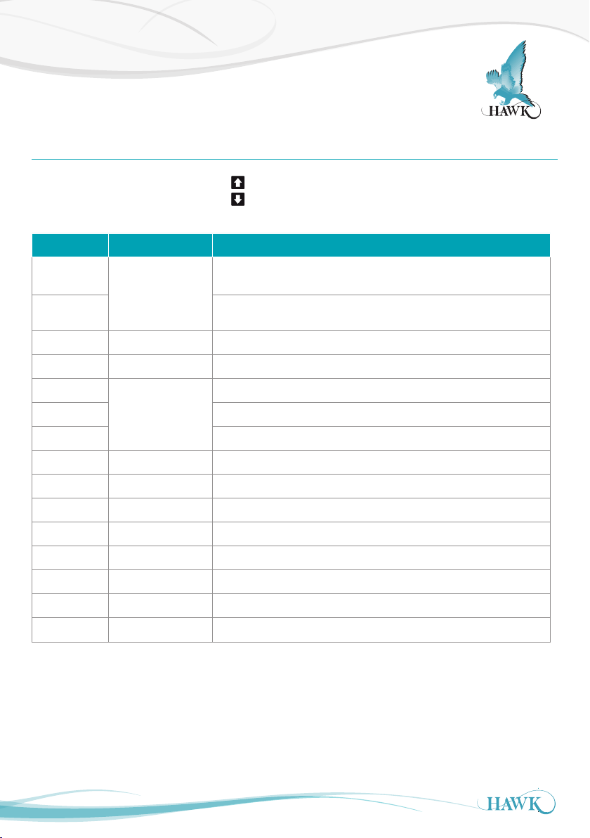
Operating Diagnostics
ORCA Sonar System
Operating State
In this operational state you can use the
measurements.
Diagnostic
Bed
Level
Bed% % Height of bed level proportionally based on High & Low level
Tx 1 Address of Transducer (default 1)
Normal
Recover Unit is searching for new signal
Failed Unit is in failsafe mode
W (down) Distance Tracking Window end point (measured from sensor face)
W (up) Distance Tracking Window star t point (measured from sensor face)
T: 23.8 Measured Temperature
N: 0.00% Noise (electrical and frequency interference)
R: 0.00% Current Recover Gain added
G: 24.6% Total amount of Gain applied to track current echo
Typical Reading
Distance
Distance
buttons to navigate through and view unit diagnostics and other
Description
Bed indicates Bed height measured from Low Level
Depth indicates depth of measured Density measured from the
transducer face
Unit is operating normally
S: 1.60V Signal size in Volts
E: Distance Non-damped measured distance measured from sensor face down
27
Page 28
Application Calibration
1/2 Submerged
4mA
Bed Depth
(Max Bed + 1m (3ft)
Max Bed
1m
ORCA Sonar System
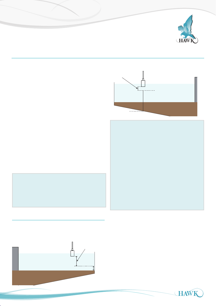
How to set up the unit - Bed Level + Hindered / settling layer measurement
Parameters for standard setups are located in the
'Quickset' menu.
You will need to program the following parameters:
- App Type - High & Low Level, Density, Bed Depth
- App Type2, High & Low Level2, Density
A) High and Low Level should be the same for
both App Types. High Level should not be less
than 0.600m (2ft).
B) Set Ap p Typ e to 'Bed' with Density 10+g/l. This
applies our pre-set parameters to measure the
Bed level with the first output.
Set Bed Depth - see Bed Depth
(1)
Set Ap p Typ e2 to 'Floc' with Density 0.6-1.2g/l.
This applies our pre-set parameters to measure
the hindered/settling layer to target with Floc
control.
App Type Notes
App Type is the primary measurement. If
measuring Bed level it should always be set to Bed
level. Density of 10+g/l is the optimum setting to
penetrate suspended material to the Bed.
Bed Depth
(1)
Blanking /
non-measured
zone
High Level
20mA
0.600m
Low Level
App Type2: Additional Settings
SmplRate - App Type2 is measured at a time
based interval. This can be reduced as low as
0.5mins (30 seconds)
Damping2 - Along with reducing SmplRate time,
increasing Damping2 will provide a smoother
output trend.
Calibr% - To see a lighter interface increase the
Calibr% parameter. Use 1% intervals and press
CAL to fire test pulses. This will return the depth
of the measured inter face and signal size. Target
1V+ signal at preferred depth. Higher% makes the
unit more sensitive to lighter material. Fire several
pulses with each adjustment.
Bed Depth should be programmed to 1m (3ft) higher
than the application expected maximum depth
Bed Depth
(Max Bed + 1m (3ft)
Max Bed
28
1m
Page 29
Application Calibration
1/2 Submerged
4mA
Bed Depth
(Max Bed + 1m (3ft)
Max Bed
1m
ORCA Sonar System
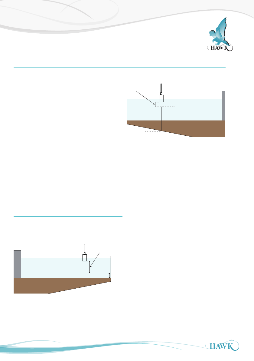
How to set up the unit - Bed Level + Clarity
Parameters for standard setups are located in the
'Quickset' menu.
You will need to program the following parameters:
- App Type - High & Low Level, Density
- App Type2, High & Low Level2
A) High Level for App Type should not be less
than 0.600m (2ft). High and Low level for Clarity
is represented as a %. 0% poor Clarity, 100%
optimal Clarity.
B) Set Ap p Typ e to 'Bed' with Density 10+g/l. This
applies our pre-set parameters to measure the
Bed level with the first output.
Set Bed Depth - see Bed Depth
Set Ap p Typ e2 to 'Clarity'. This programs output
2 for a proportional 0-100% representation of
Clarity
(1)
Blanking /
non-measured
zone
Low Level
High Level
20mA
0.600m
Bed Depth
(1)
Bed Depth should be programmed to 1m (3ft) higher
than the application expected maximum depth
Bed Depth
(Max Bed + 1m (3ft)
Max Bed
29
1m
Page 30
Application Calibration
1/2 Submerged
4mA
Bed Depth
(Max Bed + 1m (3ft)
Max Bed
1m
ORCA Sonar System
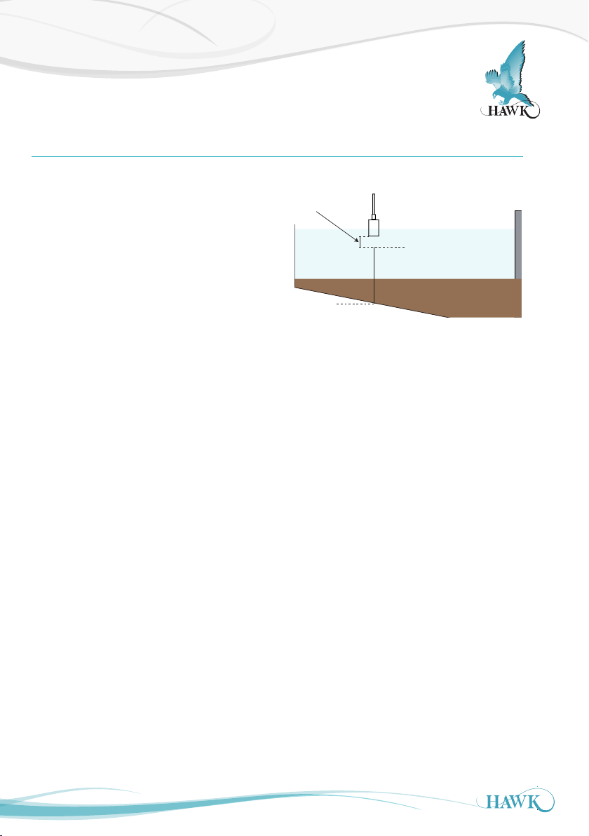
How to set up the unit - Hindered Layer + Clarity
Parameters for standard setups are located in the
'Quickset' menu.
You will need to program the following parameters:
- App Type - High & Low Level, Density
- App Type2, High & Low Level2
A) High Level for App Type should not be less
than 0.600m (2ft). High and Low level for Clarity
is represented as a %. 0% poor Clarity, 100%
optimal Clarity.
B) Set Ap p Typ e to 'Floc' with Density 0.6-1.2g/l.
This applies our pre-set parameters to measure
the Bed level with the first output.
Set Ap p Typ e2 to 'Clarity'. This programs output
2 for a proportional 0-100% representation of
Clarity
Blanking /
non-measured
Low Level
zone
High Level
20mA
0.600m
30
Page 31

Troubleshooting
ORCA Sonar System
Unit is measuring incorrect Bed or Space
• Confirm display mode is correct
• Space is measured from sensor face to target.
Bed is measured from low level to target.
• Confirm High Level, Low Level and Bed Depth (if
applicable) match application requirement.
• Increase or decrease 'Gain4'. Increasing this value
makes the unit more sensitive to to interfaces within
the tank and vice versa. Programming 'Bed Depth'
sets Gain4 to a recommended value based on the
expected depth of the Bed level
• The Parameter Slope Inc%
(Advanced Menu sof tware rev 5.81) can be used
to put more emphasis on deeper measurement -
increase this to 3%.
• High volumes of poor settling or suspended material
with attenuate the Sonar pulse. The unit may
read higher tracking suspended material if process
conditions in the tank fail.
PLC indication does not match measurement
• Disconnect the analogue wires from the amplif ier.
Use a multimeter on the 4-20mA terminals labeled
IS and + to read the direct mA from the unit. Re-
connected analogue wires and compare this value
with the reading from the control system.
• Confirm High Level and Low Level are set to the
same values in amplifier and control system.
Some menu options are missing
• HAWK is constantly updating and improving the
design and accessibility of its products and as a
result older units may have different software.
Contact your local representation for information on
updating to the latest software.
31
Page 32

Troubleshooting
ORCA Sonar System
Error Codes
Er ro r 01:
Amplifier/ Transmitter can not communicate with
transducer.
• Wiring: Check the terminals for a loose or
incorrect connection (including junction box/cable
extensions)
• Check the cables for any signs of damage
• Ensure any customer supplied cable meets
HAWK specifications
• If using junction box extension trace the 8 -10VDC
from the red/black amplifier terminals to
the transducer to ensure wires are correct
• If using a junction box ensure you follow HAWK
specification for extending cable
• ‘Unit Specs & Checks’ has additional checks for
causes of Error 01.
Error 02:
Communication data corruption between
Transmitter and Transducer.
• It can be a result of noise in data lines or one of
data lines (white or blue) being open circuit.
• Make sure wiring is correct especially look to the
screen (earth).
• Ensure you are using quality shielded
instrument cable.
• ‘Unit Specs & Checks’ has additional checks for
causes of Error 02.
Error 03:
• Specif ic comms mode is selected (eg Profibus, FF)
but comms module is not connected or responding
• Check your unit part number to ensure it has
correct comms
• If you do not have additional comms
(part number option X) then select Modbus.
Error 04:
Amplifier is programmed with incorrect software
or has wrong hardware connected.
• Contact your local suppor t.
ActuatorErr
Before the Actuator sweeps the ORCA will check
the incoming voltage to confirm it is not less than
the VoltCutOff parameter value. If it does detect the
error it will display ActuatorErr for a few seconds on
the LCD. Confirm 24VDC power supply is per spec
(min 5A at the terminal)
ActuatorVsErr
If the voltage drops below the VoltCutOff parameter
value during an attempted Actuator swing the ORCA
will display ActuatorVsErr for a few seconds on the
LCD. Confirm 24VDC power supply is per spec (min
5A at the terminal).
32
Page 33
Troubleshooting
ORCA Sonar System
Unit Specs & Health Checks
OSIR Transmitter
Specified ranges (supply dependant): 90-260VAC,
24-30VDC, 30 -48VDC). For suspected power issues
ensure user supply is appropriate & consistent. If
using VDC ensure minimum 24V 5A supply is
present or the actuator cleaning will not operate.
If using AC power you can check the power supply
for faults by reading the DC +/- terminals with a
multimeter set to DC. This terminal will produce 15-
16VDC stable. If this value is lower or inconsistent
you may a problem with the internal power supply.
Unit per formance will be affected if the unit detects
voltage below 9VDC. If ‘V in chk ’ is on the unit will
trigger its failsafe routine. If V in chk is of f the unit will
display V fail on the LCD.
Transducers
The Transducer power (red wire) should draw
8-10VDC. If this figure is too high or too low check
ORCA power & supplied power as above.
Disconnect transducer from amplifier.
There should be no open circuits between wires.
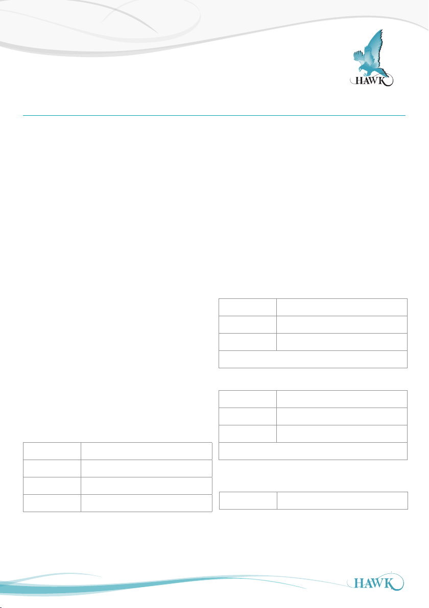
Resistances between transducer wires (approximate
values):
If any are open circuit check wiring connections or
there may be a problem with the transducer.
Transducer problems may exhibit via the amplifier
protecting itself against high current draw - measure
resistance across transducer: Red and DC:+
terminals on the amplifier while the transducer
disconnected and then connected. If the resistance
increases dramatically there is potentially a wiring or
transducer problem.
OSIRSCA (Electric Actuator)
Actuator position - disconnect the actuator wires and
read for the following values:
Default (pole should be vertical)
Black - Blue 2kohm
Blue - Brown 8kohm
Black - Brown 10kohm
Note: Lines 1 & 2 add to total of 10kohm
Peak extension (default parameters)
Black - Blue 4kohm (approx)
Blue - Brown 6kohm (approx)
Black - Brown 10kohm
Blue - White 32kohm
Black - Blue 15.6kohm
Black - Red 1-2Mohm (or OV / high resistance)
Black - White 15. 6ko hm
33
Note: Lines 1 & 2 add to total of 10kohm
Voltage draw during swing out:in - at the terminals (all
wires must be connected to amplifier).
Green - Yellow 26VDC: -26VDC
Note: The 'Actuator' LED turns on during the swing
process. If the swing fails the light stays on.
Page 34

Troubleshooting
ORCA Sonar System
ORCA Electric Actuator Troubleshooting
The ORCA Sonar system is of ten used with an
electric actuator, powered and controlled by internal
electronics in the ORCA Transmitter. This section
describes several tests which can be made on the
complete system, and on the individual parts, to try to
identif y the cause of a problem where a unit seems
not to be operating correctly.
If the Cleaner LED is illuminated with no Actuator
movement the ORCA Transmitter has attempted to
drive the Actuator but the action failed.
Wiring Checks: Confirm there are no loose or
misplaced wires.
Power Supply: Ensure that power supplied to the
instrument is within the specifications given (see unit
specs & helth checks). If DC power is used, then
the current capacity of the DC supply wiring is
critical.
Mechanical Checks:
Ensure that the actuator, bracket, transducer
mounting pipe and hinged clamps are assembled
correctly and that the pinch bolts which secure the
hinged clamps to the transducer mounting pipe are
firmly tightened. Correctly assembled hinges should
move very freely before the transducer mounting pipe
is inserted.
Software Settings:
To check for correct operation of the actuator go to
the ‘Cleaning’ parameter under ‘OutputAd’ and select
‘Actua Out’, then press CAL. The actuator should
move the transducer out to its end stop setting.
Return to the ‘Cleaning’ parameter and select ‘Actua
In’. The actuator should move the transducer back
in to its home position. Return to the 'Cleaning'
parameter and finally select ‘Actuator’ for the
standard automatic operation mode.
If the actuator does not move correctly or jitters:
If the actuator still does not operate when
commanded manually first attempt to reset the
international potentiometer.
This is done by applying voltage directly to the
Actuator wires: Disconnect the Green and Yellow
wires from the transmitter. Apply 24VDC directly to
these wires (Yellow positive, Green negative). This
will drive the actuator. After the extension stops,
remove the direct 24VDC. Re-connect the green and
yellow wires to the transmitter. After the unit attempts
a second cycle it will have detected the Actuator
at full extension and then attempt to retract it to the
default Start position.
If the Actuator still does not retract to the correct
home position connect a dif ferent power source to
the ORCA transmitter. Re-confirm the resistance and
voltage specifications are measured as per listed in
the 'Unit Spec s and Health Checks' section.
If the Actuator still does not function correctly you
may need to replace the Actuator.
34
Page 35

Part Numbering
ORCA Sonar System
Remote Electronics
Remote Electronics
Model
OSIR Sonar Level Transmitter, 3 relay alarms
Power Supply
B 24-30VDC (min 5A)
D 90-250VAC and 24-30VDC (min 5A)
Additional Communications (PC comms GosHawk standard)
X 1 x 4-20mA analog output module with Modbus
Y 2 x 4-20mA analog output modules with Modbus Comms
I 1 x 4-20mA analog output module with Modbus and HART
J 1 x 4 -20mA analog output module with Modbus and Dual Channel HART
A Profibus PA
P Profibus DP
F Foundation Fieldbus
D DeviceNet
W Modbus
N/A
X Not Required
OSIR D Y X
35
Page 36

Part Numbering
ORCA Sonar System
Remote Sonar Transducer
OSIRT ORCA Sonar Transducer
Transducer Strength
3 Industrial / Mining
Transducer
02 (150k Hz)
Facing & Housing material*
S4 Fiberglass face with Polypropylene housing (max 50°C 122°F)
SH Full fiberglass high temperature version (max 80°C 180°F)
Approval Standard
(consult safety instructions for potential IS barr ier req)
X Not Required
i0 IECEx Zone 0 (Ex ia IIA T4 IP68 Tamb -20°C to 70°C)
A0 ATEX Grp II Cat 1 GD EEx ia IIA T4 IP68 ( Tamb -20°C to 65°C)
A1 ATEX Grp II Cat 2 GD EEx m II IP68 T5 (Tamb -20°C to 65°C)
T6 (Tamb -20°C to 50°C)
i1 IECEx Zone 1 (Ex mb II IP68 T5(Tamb -20°C to 65°C)
T6 (Tamb -20°C to 50°C))
Connection
C IP68 Sealed with 6 metre cable
6 6m cable
15 15 m c able
30 30m cable
50 50m cable
FRP Full transducer / pole FRP fibreglass encapsulation
(requires OSIRMELxH) consult factory
OSIRT 3 02 SH X C 6
*Other facing & housing materials including GH and HH are now same specif ication as SH option.
36
Page 37

Part Numbering
ORCA Sonar System
Automatic Scum Cleaner
OSIRSC Automatic Scum Cleaner
Type
A 24VDC Electric Actuator incl. Mounting Accessories
B Pneumatic Actuator (please consult the factory)
D Floating Sonar with 24VDC Electric Actuator incl.
Mounting Accessories
E Impact Plate Dual Direction plus Mounting Bracket
with Mounting Accessories
OSIRSC A
Accessories
Mounting Extension
OSIRMEL Mounting Extension Stainless Steel Pipe
Length
2 2 meters
3 3 meters
4 4 meters
5 5 meters
H Full transducer / pole FRP
fibreglass encapsulation
(consult factory)
OSIRMEL 2
HAWKLink USB PC connector for GosHawkII
HAWKLink-USB
Stainless Steel Sunhood
SUNHOOD
Extra Cable (Belden 3084A)
CA-T XCC-R-C15 15m cable
CA-T XCC-R- C30 30m cable
CA-T XCC-R- C50 50m cable
CA-T XCC-R- C100 100m cable
37
Page 38

Specications
ORCA Sonar System
Sonar Frequency Selection
• 150kHz
Operating Voltage
• 90 - 260Vac 50 / 60Hz
• 24Vdc (min 5A supply)
• Residual ripple no greater than 100mV.
Power Consumption
• <10VA @ 240Vac
• <10W @ 24Vdc.
Analogue Output
• Either single or dual analogue
1 x 4-20mA (isolated) 600 ohms max
1 x 4-20mA (non isolated) 600 ohms max.
Communications
• GosHawk, HART, Modbus, Profibus DP,
DeviceNet, Foundation Fieldbus, Profibus PA.
Relay Output
• 3 x s.p.d.t. 0.5amp / 240vac
• Form c. type non-inductive load
• Fully programmable.
Maximum Range
• 65 meters.
Blanking Distance
Operating Temperature
• Remote Electronics: - 40°C to 70°C
• Sonar Transducer Polypropylene: -40°C to 50°C
• Sonar Transducer FRP Fibreglass:
-40°C to 80°C.
Transducer / Transmitter Separation
• >500m
Note: Must be BELDEN 3084A
IMPORTANT
“USE SPECIFIED CABLE ONLY”
Cable (Sonar Transducer)
• BELDEN 3084A.
Sealing
• Remote Electronics IP67
• Remote Transducer IP68.
Cable Entries
• Remote Electronics: 3 x 20mm 1 x 16mm.
Typical Weight
• Remote Electronics 1kg
• Remote Transducer 1kg
• Cleaning Mechanism 5kg.
• 450mm: 150kHz.
Resolution
• 1mm.
Accuracy
• +/- 0.25%
38
Page 39

Warranty and Liability
ORCA Sonar System
Warranty and Liability
HAWK specializes in ultrasonic, sonic and sonar level transmitters and have thousands of installed
instruments in critical applications around the world.
HAWK guarantees the ‘ ORCA’ sonar range, when delivered, is free of material defects and undertakes to
replace, repair any defective par t, free of charge. HAWK will provide two levels of warranty period.
A one year electronic warranty period extends from this delivery date. HAWK warranty, solely covers,
workmanship, material defects, only, unless specified in writing by the factory.
The warranty does not cover, wearing parts, consumables, incorrect handling, incorrect installation, or using
the instrument for anything other than what it is intended to do.
39
Page 40

A Higher Level of Performance
ORCA Sonar System
HAWK, Since 1988
Hawk Measurement Systems Pty Ltd (HAWK) was
established in 1988. It's founding members saw the
universal requirement of various industries requiring
improved process control and efficiency in their
operations.
We Can Help
HAWK understands the difficulties customers face
when seeking accurate level measurement. Every
application is different, involving a multitude of
environmental factors. This is where HAWK excels.
Our aim is to ensure that customers feel comfortable
with our technology, and are provided with long term
and reliable solutions. We believe that a combination
of application and product expertise, as well as
forward thinking and proactive support policies
are the foundation of successful customer-supplier
relationships.
Progressive Technical Support
HAWK believes that the future of the Level
Measurement Industry revolves around the quality
of pre and post sales - support. Our aim is for all
sales & support staff to be product experts, and more
importantly application exper ts making our customers
applications as ef ficient and consistent as possible.
Remote Innovation
HAWK understands the need for immediate technical
assistance.
The HAWKLink 3G communication device allows
any computer with internet access and our free
GosHawk diagnostic & calibration software; to dial in,
calibrate, test, and check the performance of HAWK
products. This innovative system allows our Global
Suppor t Team to assist with commissioning and
after sales service of HAWK equipment worldwide.
Measurement problems are addressed as they
happen; not days or weeks later.
Knowledge Sharing
HAWK believes that knowledge sharing is key to
creating long term relationships. Empowering our
customers and our worldwide distribution network,
whilst being available at all times to lend a helping
hand, is the perfect recipe for long term solutions and
relationships. HAWK openly extends an invitation to
share our 25 years of level measurement experience,
and ensure that your day to day processes are
efficient, understood, and always working.
All company or product names are registered trademarks or
trademarks of their respective owners.
Hawk Measurement Systems
(Head Ofce)
15 - 17 Maurice Court
Nunawading VIC 3131, AUSTRALIA
Phone: +61 3 9873 4750
Fax: +61 3 9873 4538
Hawk Measurement
96 Glenn Street
Lawrence, MA 01843, USA
Phone: +1 888 HAWKLEVEL (1-888-429-5538)
Phone: +1 978 304 3000
Fax: +1 978 304 1462
For more information and global representatives: www.hawkmeasure.com
DOC-OS-MAN 07/14
 Loading...