

Page 1

HA - MC01 V2
Installation Manual
Guide to intelligent Alarm Immobiliser
Manufacturer:
COMMERCIAL ELECTRONICS
264 HAYDONS ROAD, WIMBLEDON, LONDON SW19 8TT. UK
TEL: +44 020 8404 7105 FAX: +44 020 84047104
http://www.hawkcaralarm.com e-mail: [email protected]
ISO 9001
ISO
9001
C
E
R
T
I
F
I
C
A
D
O
QS 9000
Page 2

1
Installing HAWK® Motorcycle Alarm System
(General Guidance)
We think youʼve made an excellent choice in allowing HAWK® to protect your bike. Now the
question is: “How in the world am I going to install this – there are so many wires.” What seems
like a hard task is actually not too bad; however, you need to have a least some mechanical ability.
Installation is all about planning, gathering information, and careful execution. Yes, you will need to
do a little research to make your installation easier. The more information and reference diagrams,
the better. You will need to learn how to test the polarity of a wire using a digital multi-meter; see
separate section how to use digital multi-meter. Lastly, you will need your basic tools to remove
some vehicle panels to access the vehicle wiring.
Gathering Information and Reference Material
Information is the backbone of your soon to be successful installation. You should gather documents
with vehicle specific wiring colours, locations and polarities.
Planning the Alarm Install
Your plan will be the difference between a finished product and a job left for next winter. A few
minutes of planning and prepping will yield at least an hour and a half less install time. Itʼs not fun,
but it needs to be done! Begin by studying your vehicle specific diagram side by side with your bike
alarm installation diagram. Identify which features you plan to use on the alarm, not all features are
necessary. (e.g., remote starting)
Preparing the Wiring
Once you identify which items you will install along with the alarm, eliminate the unused wires to
prevent clutter. It is common practice to twist the wires of a same plug together then secure them
to each other with electrical tape. Do not wrap the entire bundle, as different wires go to different
locations. Once you finish wrapping all the harnesses tape them to each other to create one large
pigtail containing all of the used wires. This keeps the wires together, secure and free from frays
and obstruction. You will now want to identify the locations of the wires which you will connect to
on your bike. Take your harness of wires on the alarm which you just organized together, and split
it down once more into vehicle locations. Group wires into three different groupings, for example
dash, rear, and engine wires, or use your own grouping procedure. Tape these wires together in their
bundles to create individual wiring bundles.
Checking the Bike
You will need to inspect your vehicle to be sure of a few things previous to beginning the
installation process. Check your vehicle and identify which tools are needed to remove the necessary
panels. You will once again refer to your vehicle wiring diagram to find the locations of the wires
where the panels will be removed. Once done, you are ready to begin the installation.
Execution
Removing the Panels
The right tools are the difference between bloody knuckles or no sweat. We suggest you seriously
consider the specialty items, as they will be handy in other wiring projects in your future. You will
want to begin be removing the panels where your wires are located. Be sure to notate where all clips
and screws go.
Page 3

2
Wiring the Alarm Unit
Once the panels are removed, you will want to locate a good spot to mount the module. The harder
to see, the better. This will make it much more difficult for a would-be-thief. You will generally
tie strap, screw, or adhere (if adhesive pad is provided) the module to a support brace or stiff, flat
surface. Be sure to mount the unit in a location that is not too close to the engine. As a general rule
we suggest at least 12 inches from the engine. Also, if an adhesive strip is provided with your alarm
system, be sure to prep the surface with rubbing alcohol or degreaser prior to mounting. Next, run
the LED display light, siren, and external antenna, if equipped. Be sure to mount your siren in an
obscure location also. At this time, everything which will be plugged into the unit should be. Begin
by wiring any necessary relays first, if any are necessary. Getting this out of the way now will save
you from a ratʼs nest of wires. After the relays are wired, begin connecting your wires to the proper
locations. You may want to read the article on testing wires polarity before making any connections.
You should always test wires before you make a connection. Connecting the wires can be done in
a number of fashions. You can splice the wires and tape them using electrical tape. You can solder
then tape or heat shrink. You can use t-tap connectors, although we personally do not recommend
them. It is completely your preference, but we suggest soldering connections followed by heat
shrinking. Just be sure the connection is solid and free of any tension.
Congratulations, your bike is now safer!!
Your installation should now be complete. Put the panels back on the vehicle and open your alarm
manual. There should be a section which displays the functions of your alarm system; this is great
for testing your installation. Go through this process thoroughly.
Itʼs virtually impossible to install a motorcycle alarm system without a multi-meter; therefore, if you
plan to do the install, this is a must have. You can purchase a digital multi-meter for about £4.99
from Electronic Hardware e.g. Maplin. (See below for detailed instructions on using a multi-meter).
Using a Multi-meter and Testing Wires
A digital multi-meter is your safeguard when doing a motorcycle alarm. Testing wires before you
make a connection is a sure fire way to make sure you are making a proper connection. Your multimeter should have a DC setting with 2 leads, red and black: positive (+) and negative (-).
Testing Wires
When installing any electrical component into a vehicle, you will have 3 polarities which you may
need to test for. There are positive, negative and reverse polarity configurations which you must
know how to test for.
Positive (+)
When testing for a wire which should have a positive polarity, you will need to do as follows. Set
your multi-meter to 12Volts DC. Connect your black lead to chassis ground (-). Next connect your
red lead to the wire which you believe has 12volts. The meter will show 12V if that wire is positive.
The meter will show 0 if it is not.
Negative (-)
When testing for a wire which should be negative (grounded), you will need to do as follows.
Connect the red lead from your meter to 12volts constant (+). Connect the black lead to the wire you
believe is grounded. The meter should show 12V if that wire is grounded. It will show 0 if it is not.
Page 4

3
Reverse Polarity
Reverse Polarity is the combination of 2 wires operating a motor of some sort. When you activate
a reverse polarity motor, one wire goes to 12volts the other wire becomes grounded (-). When you
move the motor in the opposite direction, the leads swap polarity. To test for a reverse polarity
system, do as follows. Locate the 2 wires you believe run the motor. First, connect your red lead to
12volts constant, and then connect your black wire to ONE of the leads on the motor. Operate the
motor in each direction, notating which direction makes your meter say 12V. Now, swap your leads.
Put the black lead from the meter to ground and the red lead to the same wire you just had your
black lead on. Operate the motor in the opposite direction. If the meter shows 12volts positive (+)
when you operate it in the other direction, this is likely one of your wires.
For example…say there is a button with up and down on it and a motor with wires colored white
and black. IF you are testing the white wire, you would first connect your red lead to 12volts
constant (+) and your black lead to the wire. Press the button UP. This should make the meter say
12volts, telling us that the wire is grounded when you press UP. Now you switch your leads and
retest. The meter shows 12V again when you press down, telling us the wire is reverse polarity.
You now test the opposite wire (black in example) using the same guidelines. If it follows criteria,
then you have located your 2 reverse polarity wires.
Specific Testing Applications
Ignition Wires
12Volts with key in all positions except for ʻoffʼ
Testing an ignition wire is simple. Ignition wires are generally positive in polarity. Start by setting
your meter to DC 12V. Next, take your black lead and put it to chassis ground (-). Next, connect the
red lead to what you believe to be the ignition wire in the vehicle. It should show 0 Volts when the
key is off. Next, cycle the key through the Accessory and Ignition position. It should show 12Volts
in both positions. Next, crank and run the vehicle. It should show power even while cranking. If it
does, it is an ignition wire. If not, please read “testing an accessory wire” below. Ignition Wires
are used for motorcycles alarm and remote Starting.
Accessory Wires 12Volts with key in all positions except off and crank
Testing an accessory wire is the same as testing an accessory wire. The only exception is the meter
should show 12volts with the key in the accessory and ignition positions only. There should be 0
volts in the off and crank position. Accessory wires are used in remote starting Installations, and are
especially important on bikes with EFI.
Starter Wires 12volts ONLY in crank position
Testing a starter wire is very simple. Start by locating the suspected wire in the vehicle. Next, take
your meters black lead and connect it to ground. Next, connect the red lead to the wire you believe
is the starter wire. Crank the vehicle. The meter should ONLY show 12V when the key is in the
crank position. There should be 0 volts in all other positions. Starter Wires are used in Remote Car
Starter Installations.
Using the above testing guidelines, you can test any wire. When testing an accessory like a horn or
dome light in the vehicle, simply activate the accessory with your meter leads in place to get the
meter reading. The meter should only read power and ground on accessory items when they are
activated.
Page 5
4
Install Your HAWK compact Motorcycle Alarm System
PLANNING THE INSTALLATION
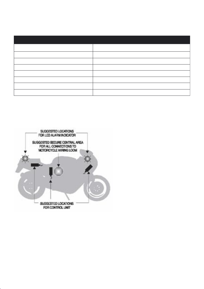
LOCATION OF MAIN SYSTEM COMPONENTS
Before commencing with the installation, plan where to secure the main components. See the
location diagram for suggested locations for the main components of the system.
CONTROL UNIT
The control Unit should be located in a protected environment with good access to the motorcycle
wiring loom. Avoid extremes of heat i.e. exhaust engine and direct exposure to the elements, and
make sure that the unit does not interfere with normal operation of the motor cycle. The control
wiring must point down to avoid any water ingress.
LED ALARM INDICATOR
The desired location of the LED Alarm Indicator should be mounted in a prominent position;
suggested locations are the instrument cluster or a rear body panel with good viewing access.
• The Control Unit • Pliers/Cable Cutters
• Two Remote Transmitters • Motorcycle wiring diagram
• Installation Instruction • Drill (9.5mm & 8mm bits)
• User Guide • Soldering Equipment
• Siren • Self Adhesive Heat sink Tubing
• Wiring Loom • Good quality insulating tape
• Warranty Information • Masking Tape
• Neck Strap & Alarm Warning Sticker • General Workshop Tools - Multi-meter
The Box Contains Tools Required
Page 6
5
INSTALLATION OF MAIN SYSTEM COMPONENTS
Great care has been take in the design and manufacture of HAWK products, Correct installation and
good working practices will enhance the operation of the alarm system and give long term benefit to
the user.
1. position and attach the Control unit
2. position and attach the LED Alarm indicator
ALARM WIRING
Plan where to make the connections to the motorcycle wiring loom. The alarm loom should run
alongside the original motorcycle loom taking full advantage of the motorcycle wiring loom
integrity. Normally all connections can be made to a central area on the motorcycle loom, such as
under the petrol tank.
NOTE: Soldered joints are recommended for all wiring connections.
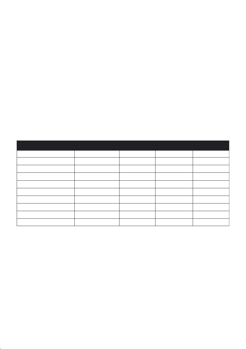
Common wiring diagram of various bikes (guidance only).
ALARM WIRING INSTALLATION
IMPORTANT
Make sure that you have planned the wiring connections before adapting / cutting the alarm loom or
the motorcycle loom.
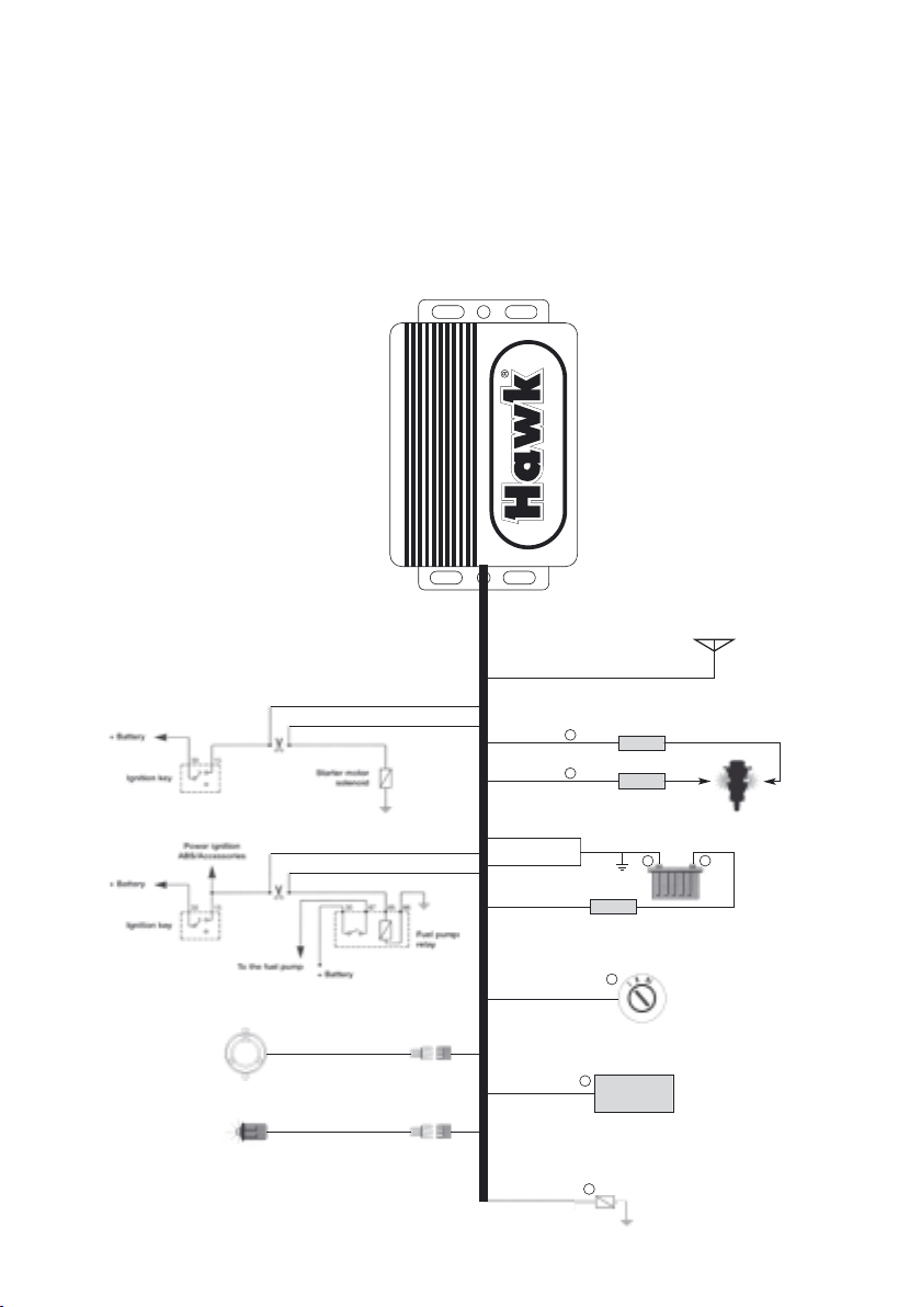
1. Connect RED wire to constant power input (+) 12v supply from the battery.
2. Connect BLACK wire to any wire in the ignition system which becomes live when
the ignition is switched ON, and remains live when the starter is pressed e.g. power
feed from ignition switch to fuse box.
3. Connect ORANGE wire to left indicator positive (+) lead output. Take care not to use
the motorcycle indicator negative (-) wire.
4. Connect LIGHT BLUE wire to right indicator positive (+) output. Take care not to
use the motorcycle indicator negative (-) wire.
5. Connect YELLOW/RED wire to the remote starter (+) lead output.
Cables of HA-MC01 v2 Function HONDA SUZUKI YAMAHA
Red Positive
Red Red Red
Green x 2
Negative Green Black/White Black
Orange
Indicator Orange Dark Green Dark Green
Light Blue
Indicator Light Blue Black Dark Brown
Black
Ignition positive Black Orange Brown
Grey
Immobiliser (1)
Grey
Immobiliser (1)
White/Black
Immobiliser (2)
Black/White
Immobiliser (2)
Yellow/Red
Remote Start Yellow/Red Yellow/Green Blue/White
Page 7
6
6. Engine immobilisation- there are 4 cables 1) BLACK/WHITE wire 2) WHITE/
BLACK wire 3) Grey 4) Grey. Recommended circuits are the starter motor
or fuel pump relay. (The CPU on Italian motorcycles or the Hall Effect ignition on
Harley Davidsons is not recommended.)
7. Connect 2 x GREEN earth wires to the motorcycle frame or the battery negative terminal.
8. Connect small 2 pin connector to LED
9. Blue wire for optional negative input sensor e.g. tilt or microwave sensor
10. Connect large 2 pin connector to Siren
IGNITION SWITCH
LIVE
BLACK ANTENNA
LED
SIREN
+
5A fuse
ORANGE
LIGHT BLUE
GREY
GREY
WHITE/BLACK
IMMOBILISER 1
IMMOBILISER
2
BLACK/WHITE
+
+
BLACK
YELLOW/RED
(REMOTE
STARTER
OUTPUT)
STARTER
SOLENOID
OPTIONAL
TI
LT/MICROWAVE
SENSOR
BLUE
(TRIGGER
INPUT)
INDICA
TORS
LEFT/RIGHT
5A fuse
-
10A fuse
GREEN
GREEN
RED
-
PERMANENT
EA
RTH
PERMANENT
LIVE
+
+
Page 8

Manufactured By Commercial Electronics . Great Britain . © Commercial Electronics 2008
www.hawkcaralarm.com
ATTENTION: Commercial Electronics always suggests installation be performed by a certified and
trained installation technician, professional installation is requirement to obtain full warranty. This
wiring information is being provided free of charge and on an “as is” basis, without any representation
or warranty to the products being installed. It is your responsibility to insure proper installation.
Commercial Electronics assumes no responsibility with regards to the accuracy or currency of
this information. Proper installation in every case is and remains the responsibility of the installer.
Commercial Electronics assumes no responsibility resulting from an improper installation, even in
reliance upon this information. Any harm or injury to the installer is in no way the responsibility of
Commercial Electronics. Any damage to the vehicle during installation or after installation is not the
responsibility of Commercial Electronics.
 Loading...