

Page 1
HA - FM10
ALARM MANUAL
Manufacturer:
COMMERCIA L E LECT RONIC S
26 4 HAYDONS ROAD, WIMBLEDON, LONDON SW19 8T T. UK
TE L: +44 02 0 8404 71 05 FAX: +44 020 8 40 4 7 10 4
http://www.hawkcaralarm.com e-mail: [email protected]
Manufactured by Commercial Electronics. Great Britain. © Commercial Electronics 2013.
HA - FM10
Page 2

Warning! Safety rst
Remote Engine Start
When properly installed, this system can start the vehicle via a command signal from
the remote control transmitter.
erefore, never operate the system in an enclosed area or partially enclosed area
without ventilation (such as a garage). It is the user’s sole responsibility to properly
handle and keep out of reach from children all remote control transmitters to assure
that the system does not unintentionally remote start the vehicle. THE USER
MUST INSTALL A CARBON MONOXIDE DETECTOR IN OR ABOUT THE
LIVING AREA ADJACENT TO THE VEHICLE. ALL DOORS LEADING FROM
ADJACENT LIVING AREAS TO THE ENCLOSED OR PARTIALLY ENCLOSED
VEHICLE STORAGE AREA MUST AT ALL TIMES REMAIN CLOSED. ese
precautions are the sole responsibility of the user.
Use of this product in a manner contrary to its intended mode of operation may result
in property damage, personal injury, or death. (1) Never remotely start the vehicle with
the vehicle in gear, and (2) Never remotely start the vehicle with the keys in the ignition.
e user must also have the neutral Safety feature of the vehicle periodically checked,
wherein the vehicle must not remotely start while the car is in gear. If the vehicle starts
in gear, cease remote start operation immediately and consult with the authorized dealer
to x the problem.
OPERATION OF THE REMOTE START MODULE IF THE VEHICLE STARTS IN
GEAR IS CONTRARY TO ITS INTENDED MODE OF OPERATION. OPERATING
THE REMOTE START SYSTEM UNDER THESE CONDITIONS MAY RESULT IN
PROPERTY DAMAGE OR PERSONAL INJURY. YOU MUST IMMEDIATELY CEASE
THE USE OF THE UNIT AND SEEK THE ASSISTANCE OF AN AUTHORIZED
DEALER TO REPAIR OR DISCONNECT THE INSTALLED REMOTE START
MODULE. HAWK CAR ALARM WILL NOT BE HELD RESPONSIBLE OR PAY FOR
INSTALLATION OR REINSTALLATION COSTS.
Note:
Range of LCD Alarm system is based on line of sight, unobstructed testing in ideal
conditions. Actual range will vary due to local conditions including but not limited
to environment, terrain, physical obstructions, vehicle location and orientation
interference and other possible impediments.
Page 3

CONTENTS
FUNCTION ICONS .........................................................1
BUTTON FUNCTION .......................................................2
LCD FEATURES ............................................................2
FUNCTION ................................................................3
1. Programming setting ...................................................3
2. Arm ..................................................................5
3. Disarm ............................................................... 5
4. Check car condition ....................................................5
5. Car nder ............................................................. 6
6. Anti-Hijacking ........................................................ 6
7. SOS ..................................................................6
8. Warning for low voltage of car storage battery .............................. 6
9. Dual Stage Shock Sensor ................................................6
10. Door alarm delay .....................................................7
11. Pulse for central lock .................................................. 7
12. Auto door closing when driving ......................................... 7
13. Channel 1 output (break line) choosing ..................................7
14. Channel 2 output choosing .............................................8
15. Clock setting ......................................................... 8
16. Temporary isolation of shock sensor .....................................8
17. European mute mode ON/OFF .........................................9
18. Valet mode ON/OFF ..................................................9
19. Auto arm function ON/OFF ........................................... 10
20. Remote controller vibration ON/OFF (optional) .........................10
21. Set siren volume for LCD remote fob ...................................10
22. SRP (Safe roadside parking ) function ON/OFF ..........................11
23. Power disconnecting memory .........................................11
24. Trigger memory .....................................................11
25. Trigger status identication ............................................11
26. Engine auto start work time setting .....................................11
27. Remote engine start under automatic gear ...............................11
28. Starter ON delay before engine start (Diesel mode) .......................12
29. Reservation mode (Gear mode) ........................................12
30. Outer device trigger start function. . . . . . . . . . . . . . . . . . . . . . . . . . . . . . . . . . . . . . 13
31. Turbo function ......................................................13
32. Timely auto start function ............................................14
33. Low temperature auto start function ...................................14
34. Low car storage battery level auto start function ..........................15
35. Call from the car function ............................................15
36. Revise PIN code ..................................................... 15
37. Remote controller learning ............................................16
38. Emergency disarm ................................................... 16
39. Emergency set arm ...................................................16
40. Attention for installation .......................................... 17-23
41. System parameters ...................................................23
INSTALLATION DIAGRAM .............................................. 24-25
CENTRAL LOCK INSTALLATION DIAGRAM ............................. 26-29
OTHER DIAGRAMS .......................................................30
Page 4
1
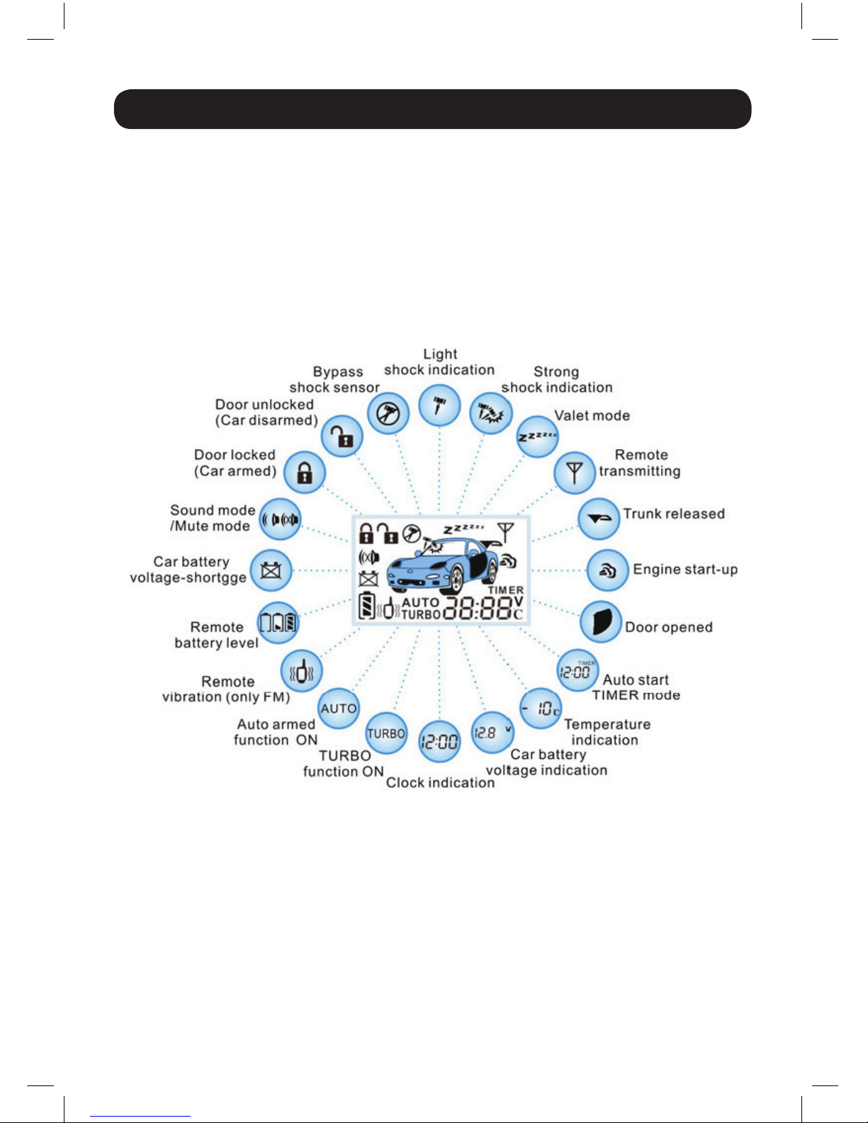
FUNCTION ICONS
Page 5
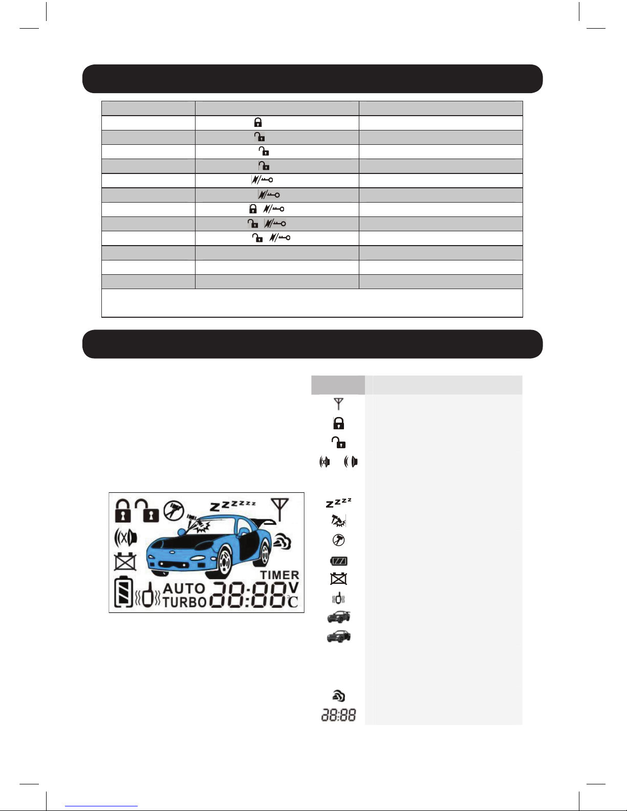
BUTTON FUNCTION
System status Button Function
Ignition OFF I ( ) 0.5 sec Arm / Car finder
Ignition OFF II ( ) 0.5 sec Disarm
Ignition OFF II ( ) 2 sec Remote engine start
Ignition ON II ( ) 2 sec SOS
Any III ( ) 0.5 sec Check car condition
Any III ( ) 2 sec Channel 2 output
Ignition ON I +III ( + ) 0.5 sec Revise PIN code
Ignition ON II+III ( + ) 0.5 sec Anti car-jacking
Ignition ON II+III ( + ) 2 sec Programming setting
Any IV ( F ) 2 sec “ F ” function setting
Any V ( * ) 0.5 sec LCD Back light ON 3 sec
Any V ( * ) 2 sec LCD Back light ON 60 sec
“ F ” function: you can choose different function in the menu, press button I to ON, press
button II to OFF.
BUTTON FUNCTION
System status Button Function
Ignition OFF I ( ) 0.5 sec Arm / Car finder
Ignition OFF II ( ) 0.5 sec Disarm
Ignition OFF II ( ) 2 sec Remote engine start
Ignition ON II ( ) 2 sec SOS
Any III ( ) 0.5 sec Check car condition
Any III ( ) 2 sec Channel 2 output
Ignition ON I +III ( + ) 0.5 sec Revise PIN code
Ignition ON II+III ( + ) 0.5 sec Anti car-jacking
Ignition ON II+III ( + ) 2 sec Programming setting
Any IV ( F ) 2 sec “ F ” function setting
Any V ( * ) 0.5 sec LCD Back light ON 3 sec
Any V ( * ) 2 sec LCD Back light ON 60 sec
“ F ” function: you can choose different function in the menu, press button I to ON, press
button II to OFF.
LCD FEATURES
Icons Icon Description
Signal transmitting
Door locked (Car armed)
Door unlocked (Car disarmed)
/ Mute mode / Sound mode
AUTO
Auto arm ON
Valet mode
Triggered by shock sensor
Bypass shock sensor
Remote battery level
Car battery voltage-shortage
Remote vibration
Trunk release
Door opened
TURBO
TURBO ON
TIMER
Auto start TIMER mode
Engine start-up
Clock indication
2
BUTTON FUNCTION
LCD FEATURES
Page 6
FUNCTION
1. Programming setting
System can program functions, please follow steps below:
1. Disarm the system, then switch ON ignition;
2. Press and hold II+III 2 sec, LED will ash once – pause – ash once , and siren
will sound 1 sec . It means that user come to program mode and stay in the 1st
level. Within 20 sec, you can press button I, II, III to conrm the function.
3. Follow below step within 20 sec (If nobody presses button or somebody switch
OFF ignition, system will exit program setting mode, LED will stop ash):
Press emergency switch twice within 2 sec, program mode will come from 1st
level to 2nd level, siren will sounds twice to conrm, LED will ash twice – pause
– ash twice.
en press emergency switch 3 times within 3 sec to come next point, Siren
sounds 3 times and LED ashes 3 times – pause – ash 3 times.
If user needs to come 11th level, please press emergency switch 11 times within
11 sec, siren will sound 11 times, LED will ash 11 times – pause – ash 11
times.
4. Press and hold II 2 sec, if siren sounds 2 sec, all F function and program setting
will be default setting (underlined in part).
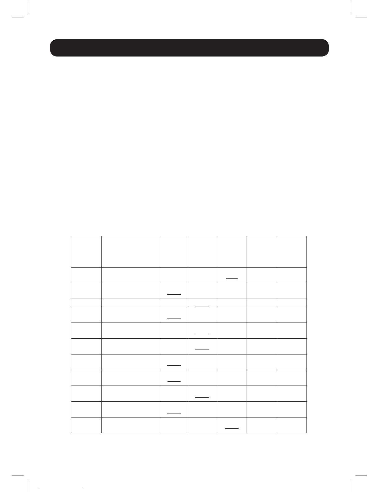
Programming table
FUNCTION
1. Programming setting
System can program functions, please follow steps below:
①Disarm the system, then switch ON ignition;
②Press and hold II+III 2 sec, LED will flash once – pause – flash once , and siren will
sound 1 sec . It means that user come to program mode and stay in the 1st level. Within 20
sec, you can press button I, II, III to confirm the function.
③Follow below step within 20 sec (If nobody presses button or somebody switch OFF
ignition, system will exit program setting mode, LED will stop flash):
Press emergency switch twice within 2 sec, program mode will come from 1st level to 2
nd
level, siren will sounds twice to confirm, LED will flash twice – pause – flash twice.
Then press emergency switch 3 times within 3 sec to come next point, Siren sounds 3
times and LED flashes 3 times – pause – flash 3 times.
If user needs to come 11th level, please press emergency switch 11 times within 11 sec,
siren will sound 11 times, LED will flash 11 times – pause – flash 11 times.
④Press and hold II 2 sec, if siren sounds 2 sec, all F function and program setting will be
default setting (underlined in part).
Programming table
Function
level
Description of
function
Press
I,
Siren
1 chirp
Press
II,
Siren
2 chirps
Press
III,
Siren
3 chirps
Press
I + II,
Siren
4 chirps
Press
I + III,
Siren
5 chirps
1
st
Door alarm delay
time
5 sec 30 sec OFF
2
nd
Pulse for central
lock
Ver. 1 Ver.2 Ver.3 Ver.4 Ver.5
3
rd
Central lock auto Ver.1 Ver.2
4
th
Break line (CH1)
Method choosing
Ver. 1 Ver.2
5
th
Enabling impulse
length for CH2
Ver.1 Ver. 2 Ver.3
6
th
Safe roadside
parking function
Ver. 1 Ver.2
7
th
Starter operation
time for auto start
Ver. 1 Ver.2 Ver.3 Ver.4 Ver.5
8
th
Starter ON delay
before engine start
2sec 5sec 10sec
9
th
IGN2 ON/OFF at
remote start-up
Ver. 1 Ver.2 Ver.3
10
th
Trunk/hood trigger
setting
Ver. 1 Ver.2
11
th
Temperature reach
high level
Ver. 1 Ver.2 Ve r.3
3
Page 7

Description of programming functions:
1st: Alarm delay time for dome-light delay: 5 sec / 30 sec / OFF
2nd: Pulse length for central lock
Version 1: 0.5 sec to close, 0.5 sec to open
Version 2: 3.5 sec to close, 3.5 sec to open
Version 3: 0.5 sec to close, two 0.5 sec pulses to open
Version 4: two 0.5 sec pulses to close, two 0.5 sec pulses to open
Version 5: 25 sec to close, 0.5 sec to open
3rd: Central lock auto function
Version 1: Ignition ON, press foot brake, central lock closes automatically;
Ignition o, central lock open automatically
Version 2: Ignition ON, press foot brake, central lock do not close ;
Ignition o, central lock do not open
4th: Break line (Channel 1) method choosing
Version 1: Break line output –250mA constant pulse when armed
Version 2: Break line output –250mA constant pulse when disarmed
5th: Enabling impulse length for Channel 2
Version 1: Channel 2 output –250mA pulse 25 sec for closing windows when armed.
Version 2: Channel 2 output –250mA pulse 0.8 sec for opening trunk when press
button III 2 sec
Version 3: Channel 2 output –250mA potential pulse 30 sec when press button III
2 sec
6th: SRP (Safe roadside parking) function
Version 1: Lights ashes 15 times when open the door
Version 2: Lights do not ash when open the door
7th: Starter operation time for auto start-up
Version 1: ree start-up time is 0.5 sec, 1 sec, 2sec
Version 2: ree start-up times is 0.8 sec, 1 sec, 2sec
Version 3: ree start-up times is 1 sec, 1sec, 1sec
Version 4: ree start-up times is 2 sec, 2 sec, 2sec
Version 5: ree start-up times is 3 sec, 3 sec, 3sec
8th: Starter ON delay before engine start: 2 sec / 5 sec / 10 sec
9th: IGN2 signal at auto start-up
Version 1: IGN2 appear 12V all the time when auto start-up
Version 2: IGN2 appear 12V before starting, 0V during start, 12V aer start
Version 3: IGN2 appear 0V before starting, 0V during starting, 12V aer staring
10th: Trunk/hood triggers setting
Version 1: Nothing trigger when trunk/hood is closed, “–” trigger when trunk/
hood is opened
Version 2: “–” trigger when trunk/hood is closed, nothing trigger when trunk/hood
is opened
11th: Temperature rich high level and car storage battery high level setting
Version 1: Engine automatically stops when its temperature exceeds 70°c or battery
voltage reaches 15.5V.
Version 2: Engine automatically stops when its temperature exceeds 80°c or battery
voltage reaches 15.5V.
Version 3: Engine automatically stops when its temperature exceeds 90°c or
battery voltage reaches 15.5V.
4
Page 8
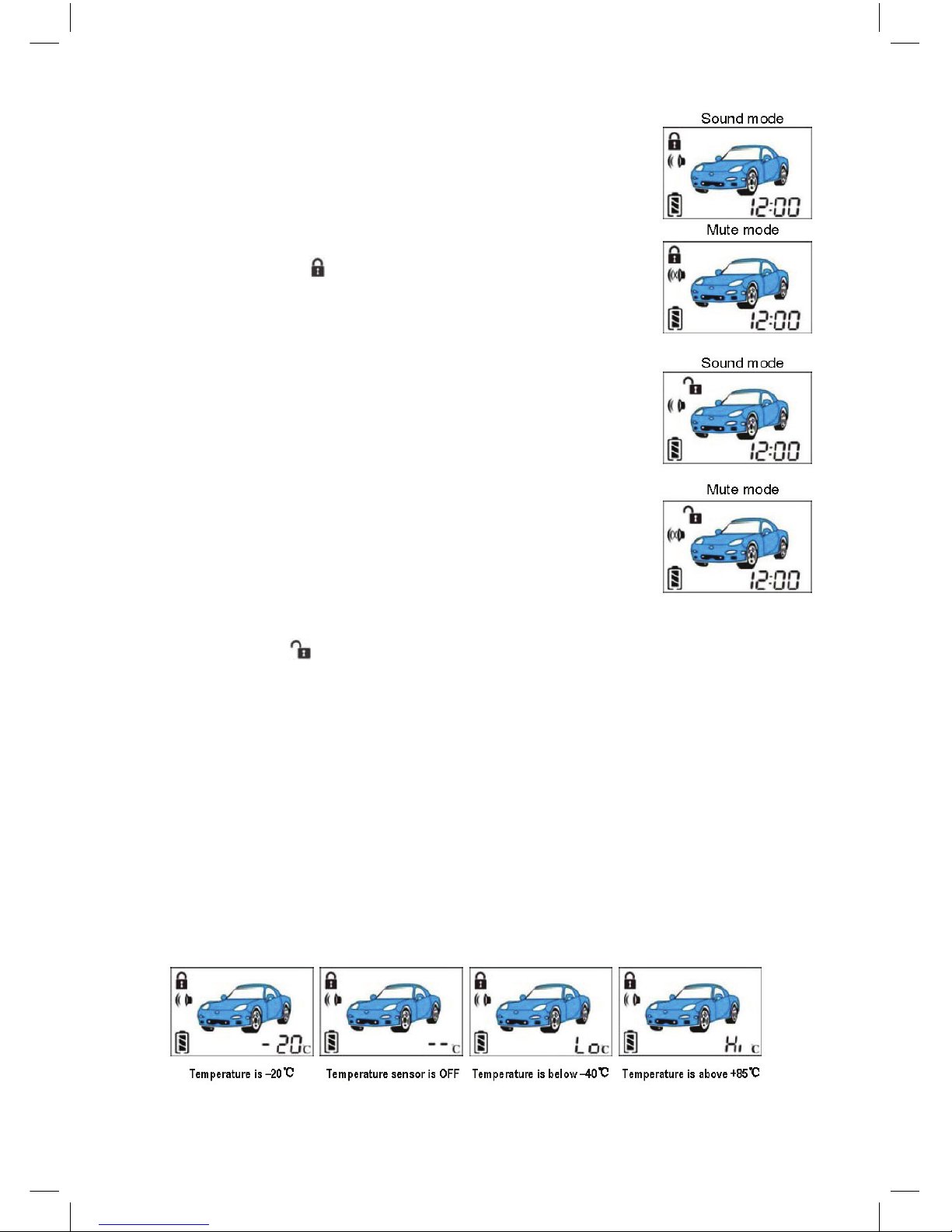
2. Arm
To arm your system within proper operation range, press but-
ton I shortly (while system in disarmed and Acc o position).
Siren will sound once (siren will not sound in mute mode),
lights ash once, doors lock, disable engine starter, and LED
will ash slowly.
Remote controller will sound “Bi-”, LCD screen will ash 5
times, and show “ ” .
If the security system is armed at the same time that an input
is active (such as door opened or hood / trunk opened or
shock sensor is triggered), siren will sound and lights will
ash.
3. Disarm
To disarm your system within proper operation range, press
button ll shortly.
Siren will sound twice (siren will not sound in mute mode),
lights will be on twice, doors will unlock, enable engine started. If nobody opens the door, LED will ash quickly. Before
disarming your system, if door is opened or ignition on, LED
will ash twice per second. If trunk is opened illegally, LED
will ash 3 times per second. If shock sensor is triggered, LED
will ash 4 times per second. At this time, if you switch ON
ignition, LED will stop ash.
Remote controller sounds “Bi- Bi-”, LCD screen will ash 5 times,
and will show “ ”.
If nobody opens the door and enters into the car within 30 sec, system will arm
automatically.
4. Check car condition
When you change battery for remote controller, please press button III shortly, all
data of F function setting (TIMER1 and TIMER2 except) will be sent to remote
controller within 3 sec.
If you press button III shortly again, remote controller will sound “Bi-”, LCD screen
will ash 5 times, and will show car temperature. If you press button III shortly
again, LCD screen will show car battery voltage.
1. Check car temperature
System check car temperature with a sensor, we suggest that you can install this sen-
sor in the surface of engine. e range of temperature is –40°c to +85°c. In a variety
of conditions, the LCD screen shows the following:
5
Page 9
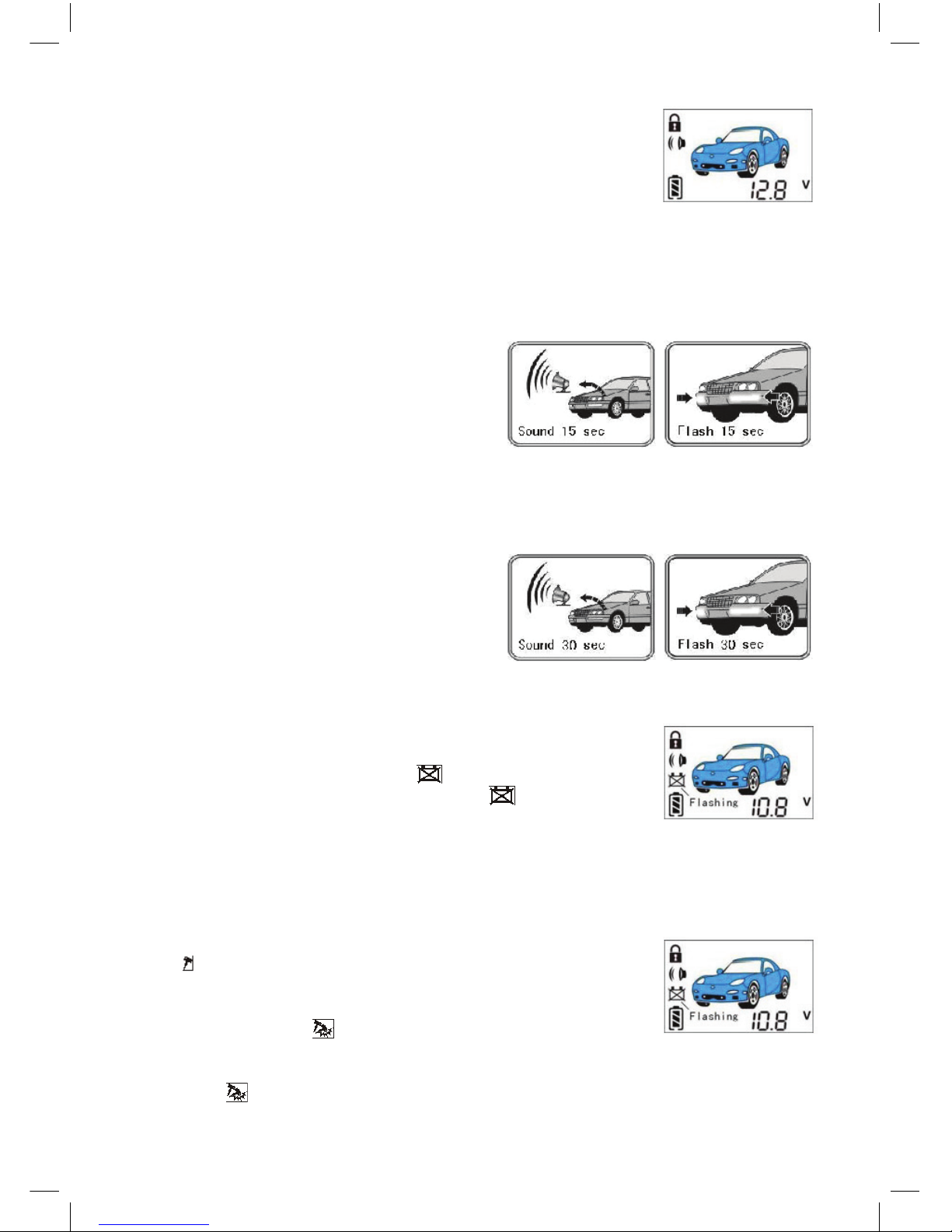
2. Check car battery voltage
System can check car battery voltage, if voltage is 12.8V, remote
controller LCD screen shows the right picture like here.
5. Car nder
In arm status, press button I shortly, siren sound 4 times (siren
will not sound in mute mode), turning light ash at the same
time for car nder. Remote controller will sound “Bi-”, LCD screen
will ash 5 times.
6. Anti-Hijacking
While driving, press button II + III
shortly while meeting the threaten or in
urgent circumstance, siren will sound and
lights will ash sharply, system enters into
Anti-Hijacking status. 15 sec later, system
will enter into arm status unconditionally,
when car is immobilised, it will not be started again.
Press button II shortly can stop this function within 15 sec.
7. SOS
When driving, press and hold button II
2 sec in urgent circumstance, siren will
sound 30 sec continuously and lights will
ash at the same time for SOS.
Press button II shortly can stop this func-
tion.
8. Warning for low voltage of car storage battery
When car battery voltage is lower than the initialization
(11.0V), main unit will send signal to remote controller, remote
controller will warn and show “ ” and the car battery volt-
age will remind car owner. At this time, “ ” will ash con-
tinuously, and the buzzer will sound once at regular intervals to
remind car owner till the car owner press button to release warning.
If switch on ignition, system will not test voltage of car storage battery.
9. Dual Stage Shock Sensor
In arm status, if car body is hit soly, siren will sound 5 times, and lights will ash 5
times; remote controller will sound, and LCD screen will show
“ ”.
If car body is hit heavily, siren will sound 25 times and lights
will ash 25 times; remote controller will sound and LCD
screen will show “ ”.
When alarm triggered, press button I can stop warn, but system
still in arm status. If users do not press any button to stop this warn, screen will
show “ ” till user stop it.
6
Page 10

10. Door alarm delay
System default setting door alarm delay is OFF, in this mode:
1. Press button I to set arm, if door (or trunk) do not be closed properly, siren will
sound 3 times and lights will ash 3 times (in mute status, only lights ash 3 times),
which can warn car owner to close door and set arm again. System will not warn
again otherwise door is closed and opened again.
At the same time, remote controller beep will sound“Bi-Bi-Bi”. If door do not be
closed properly, LCD screen will show “ ”. If trunk do not be closed properly,
LCD screen will show “ ”. Beep will sound “Bi-” each 30 sec to remind car
owner to lock the door and trunk. When closed door and trunk properly, remote
controller will not warn again.
2. While setting arm, door (or trunk) is closed properly, 2 sec later, if you open the
door, system will alarm.
If car has interior light delay, please set alarm delay time 5 sec (or 30 sec), in this mode:
1. Press button I to set arm, if door (or trunk) do not be closed properly, system en-
ter into arm status, system will not remind car owner to close the door and will not
warn. Otherwise, when the car owner set arm 2 sec later, close the door and open
again, 5 sec (or 30 sec) later siren will sound and lights will ash at the same time.
If boot is not be closed properly, siren will sound 3 times, and lights will ash 3
times. (In mute mode, only lights ash 3 times). At the same time, remote controller
beep will sound and screen will show “ ”, Beep will sound “Bi-” each 30 sec to
warn the user to close the trunk properly.
2. While setting arm, door (or boot) is closed properly, system will arm aer open-
ing the door 5 sec (or 30 sec).
11. Pulse for central lock
System default setting is electric lock, 0.5 sec to close and 0.5 sec to open. If need,
you can set program to select pneumatic lock, 3.5 sec to close and 3.5 sec to open.
If you need two-step opening door function, you can set program to select pulse 0.5
sec to close and two pulses 0.5 sec to open.
Also, you can set other pulses for central lock with programming table.
12. Auto door closing when driving
System default setting auto door closing function is OFF, you can set program to ON.
While driving, user can press button I to lock the central lock, or press button II to
unlock, but system will not be armed or disarmed.
When switch ON ignition, you can close the door and step on foot brake, central
lock will be locked automatically for safety driving. When switch OFF ignition,
central lock will be unlocked automatically for easily getting o or getting on.
If a passenger needs get o during trac, you can unlock the central lock, then step
on the foot brake, central lock is not locked to facilitate the passengers to get o.
When you open the door, and get o then closed the door, step on the foot brake,
lock function is automatically restored.
13. Channel 1 output (break line) choosing
System default setting is the main unit channel 1 output -250mA pulse for N.C.
engine stopper when armed. You can set program to output -250mA pulse for N.O.
engine stopper when disarmed.
7
Page 11
14. Channel 2 output choosing
Channel 2 output can program to 0.8 sec pulse for opening trunk, 25 sec pulse for
closing window, or 30 sec potential pulse. Factory default setting is 0.8 sec.
1. Remote open boot
Press and hold button III 2 sec, the main unit channel 2 output
-250mA pulse 0.8 sec to open the boot. Remote sound “Bi-”
and screen shows “ ”.
Note:
1. Lever boot can not be opened.
2. In arm status, open the boot, system will be disarmed and door will be unlocked.
3. In arm status, if boot is opened illegally, siren will sound 25 sec, and lights will
ash at the same time, car can not be started. Remote will show “ ” and will
sound “Bi-Bi-Bi-”.
2. Close window(comfort output)
Simply press button I shortly to arm your system, the main unit channel 2 output
-250mA pulse 25 sec to close window. Simply press button II will stop close win-
dow, the same time system will be disarmed.
3. Potential pulse
Press and hold button III 2 sec, the main unit channel 2 output -250mA potential
pulse 30 sec, you can press and hold button III 2 sec to stop it.
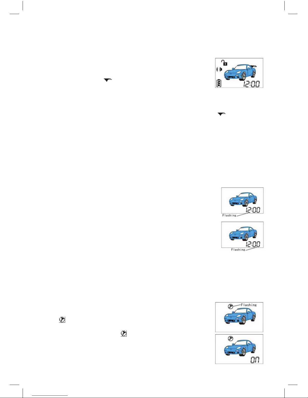
15. Clock setting
Press and hold button IV ( F )2 sec, remote controller sound “Bi-”
, clock hour gure will ash and system enter into clock hour set-
ting status. At this time, press button I shortly, gure will add 1,
press and hold button I , gure will add 1 continuously. Press but-
ton II shortly, gure will reduce 1, press and hold button II , gure
will reduce 1 continuously. Press button III shortly to conrm.
Press button IV ( F ) shortly, remote controller sounds “Bi-”, clock
minute gure will ash, system will enter into clock minute setting
status. At this time, press button I shortly, gure will add 1, press
and hold button I , gure will add 1 continuously. Press button II
shortly, gure will reduce 1, press and hold button II , gure will reduce 1 continu-
ously. Press button III shortly
Press and hold button IV ( F ) 2 sec, remote controller sounds “Bi-Bi-”, clock setting
exit. If user do not press and hold button IV ( F ) 2 sec to exit aer setting, time
gure will ash 10 sec to exit automatically.
16. Temporary Isolation of Shock / Ultrasonic Sensors
Press and hold button IV ( F ) 2 sec, then press button IV ( F )
shortly many times, till remote controller LCD screen icon
“ ” ashes.
At this time, press button I shortly, remote controller sound
“Bi-”, LCD screen shows “ ON ”, shock sensor alarm func-
tion is ON, system can receive shock sensor alarm signal.
8
Page 12
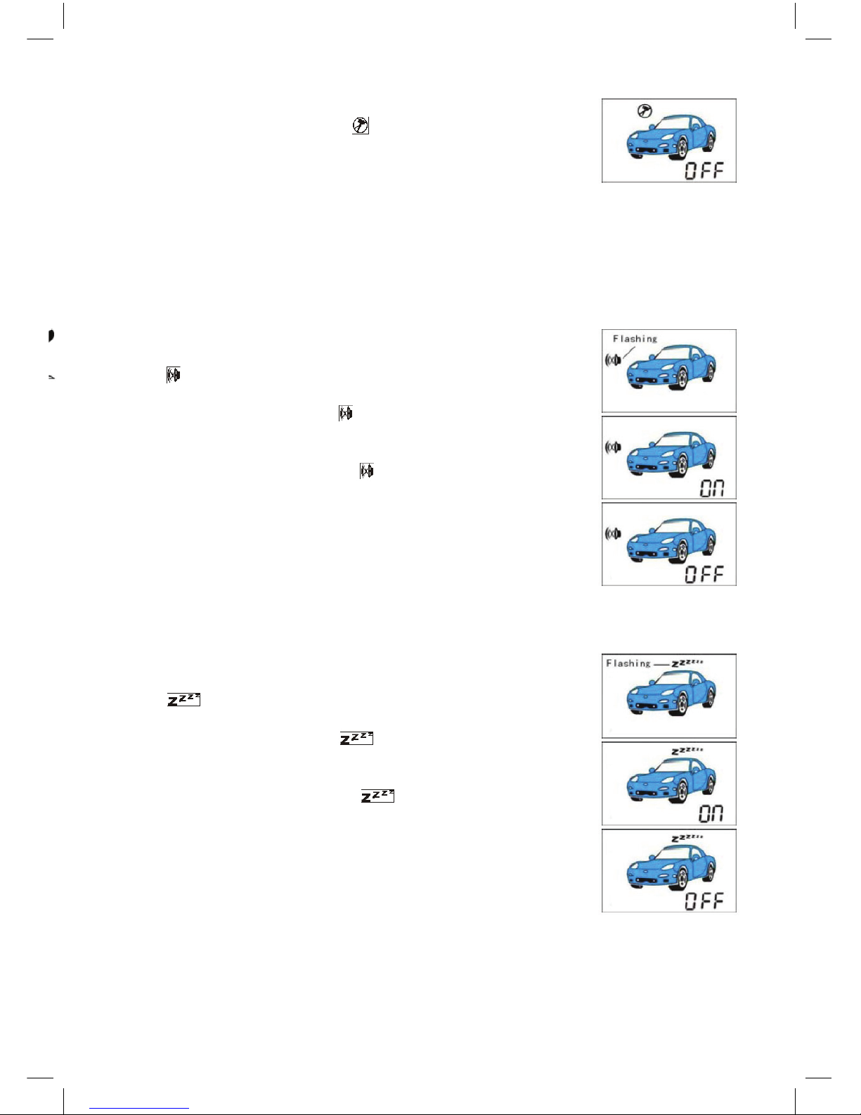
At this time, press button II shortly, remote controller sound
“Bi-Bi-”, LCD screen show “ OFF ”, shock sensor alarm
function is OFF, system can not receive shock sensor alarm
signal.
Hint:
If you do not need shock sensor, it is possible to temporarily disconnect the sensor
when leaving children or pets in the car. You can set it to o this function.
Note:
When re-power the remote and control the main unit, this function will be recov-
ered to default setting. It means system has shock sensor alarm function.
17. European mute mode ON/OFF
Press and hold button IV ( F ) 2 sec, then press button IV ( F )
shortly many times, till remote controller LCD screen icon
“ ” ashes.
At this time, press button I shortly, remote controller sound
“Bi-”, LCD screen shows “ ON ”, Europe mute function is
ON.
At this time, press button II shortly, remote controller sound
“Bi-Bi-”, LCD screen shows “ OFF ”, Europe function is
OFF, siren will sound.
Set European mute mode ON, press button I shortly to set arm,
lights ash once but siren will not sound, and you can press
button I shortly again within 5 sec to check system status,
lights ash once and siren will sound.
In this mode, siren will not sound (except: car is stolen or in
Anti-Hijacking mode, siren will sound unconditionally).
18. Valet mode ON/OFF
Press and hold button IV ( F ) 2 sec, then press button IV ( F )
shortly many times, till remote controller LCD screen icon
“ ” ashes.
At this time, press button I shortly, remote controller sounds
“Bi-”, LCD screen shows “ ON ”, valet mode is ON, all
functions will be stop except open and close central lock.
At this time, press button II shortly, remote controller sounds
“Bi-Bi-”, LCD screen shows “ OFF ”, valet mode is OFF,
all function can be used.
Note:
When re-power the remote and control the main unit, this
function will be recovered to default setting, and all function
can be used.
9
Page 13
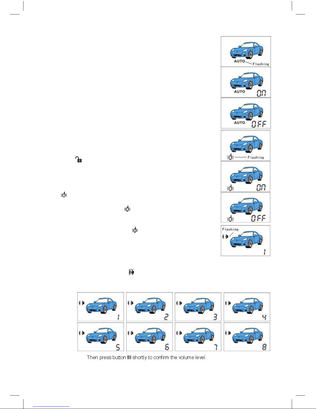
19. Auto arm function ON/OFF
Press and hold button IV ( F ) 2 sec, then press button IV ( F
) shortly many times, till remote controller LCD screen icon “
AUTO ” ashes.
At this time, press button I shortly, remote controller sounds
“Bi-”, LCD screen shows
“ AUTO ON ”, auto arm function is ON.
At this time, press button II shortly, remote controller sounds
“Bi-Bi-”, LCD screen shows “ AUTO OFF ”, auto arm function
is OFF.
Set auto arm function ON, stop engine, get o the car, close
the door properly, if user do not set arm, 10 sec later, siren will
sound 3 times and turning light ash 3 times, system activate
break line but doesn’t enter into arm status 30 sec later, and
central lock will not be locked.
At the same time, remote controller received the signal, if the
door is not locked, beep will sound. en, LCD screen will
show “ ”.
20. Remote controller vibration ON/OFF (optional)
Press and hold button IV ( F ) 2 sec, then press button IV ( F )
shortly many times, till remote controller LCD screen icon
“ ” ashes.
At this time, press button I shortly, remote controller sounds
“Bi-”, LCD screen shows “ ON ”, remote controller vibration
function is ON.
At this time, press button II shortly, remote controller sounds
“Bi-Bi-”, LCD screen shows “ OFF ”, remote controller
vibration function is OFF.
21. Set siren volume for LCD remote fob
You can set siren volume.
Press and hold button IV ( F ) 2 sec, then press button IV ( F ) shortly many times,
till the remote screen icon “ ” ashes.
At this time, press button I shortly or press button II shortly select the volume from
1st level to 8th level, remote screen shows:
10
Page 14
22. SRP (Safe roadside parking) function ON/OFF
System default setting SRP function is OFF, you can set it to ON.
If you park the car roadside and open the door, lights will ash 15 times to warn.
23. Power disconnecting memory
When re-powered, system will keep the original status before power o.
24. Trigger memory
When disarm, if car is triggered (shock or opening doors), siren will sound 4 times
and lights will ash 4 times. Otherwise, siren will sound twice and lights will ash
twice (in mute status, siren will not sound).
25. Trigger status identication
If the alarm system is triggered under the state of arm, there will be two ways of
warning: one is hitting (such as the car door and windows by hit or external impact,
etc.), the siren will sound intermittently (in the state of mute only the lights ash,
the siren does not sound); the other is trigger (such as the car door is opened or the
engine is started), the siren will sound continuously.
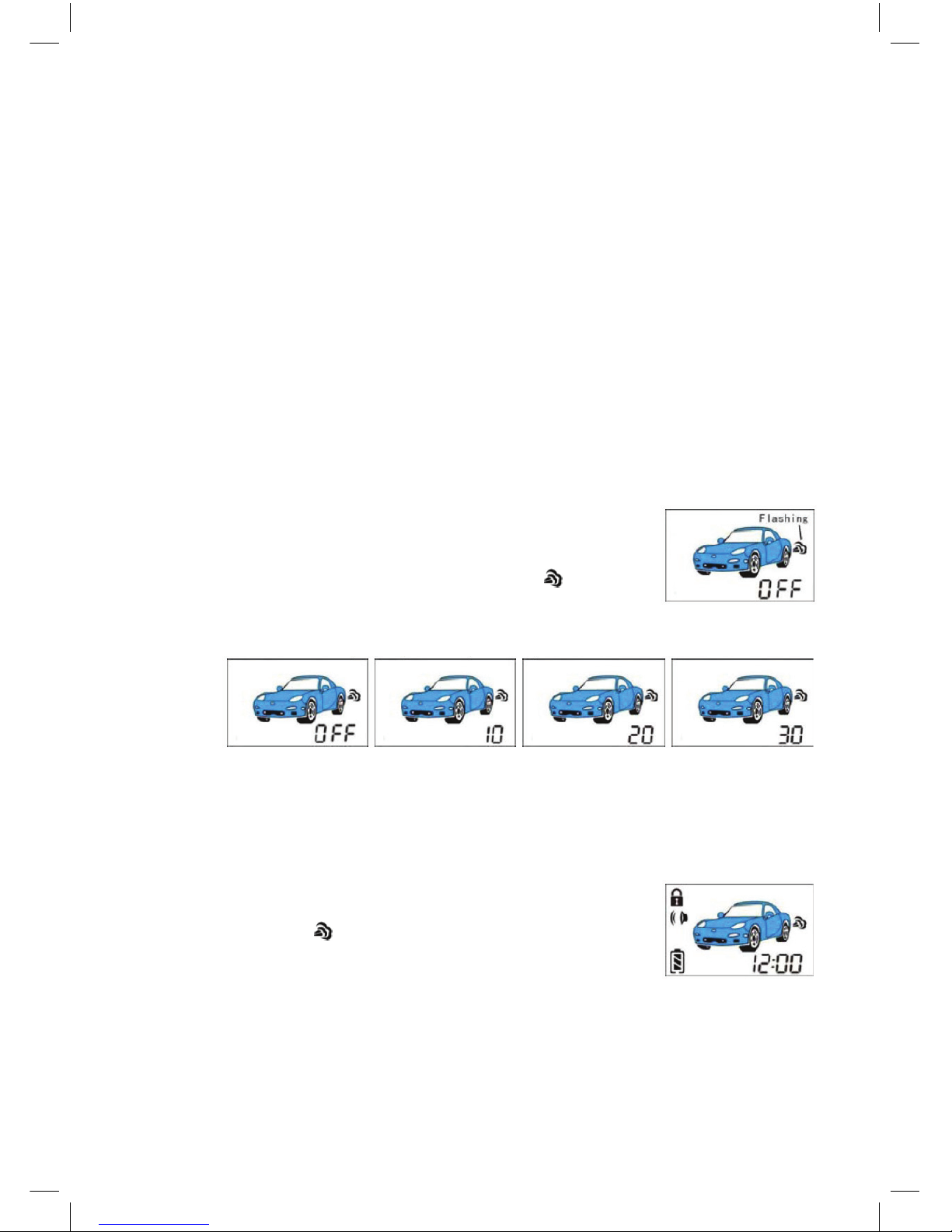
26. Engine auto start work time setting
System default setting, auto start function is OFF. You can set
engine work 10 min or 20 min or 30 min.
Press and hold button IV ( F ) 2 sec, then press button IV ( F )
shortly many times, till the remote screen icon “ ” ashes.
At this time, press button I shortly or press button II shortly
to select the time OFF, 10 min, or 20min, or 30 min, remote
screen shows:
en press button III shortly to conrm.
If user sets start function OFF, when remote controller enters into F function, LCD
screen will not show low temperature auto start, low car storage battery level auto
start and Timely auto remote engine start.
27. Remote engine start under Automatic Gear
In engine o status, press and hold button II 2 sec, if engine
is started, lights will ash slowly, and remote controller LCD
screen will show “ ”.
At this time, engine work 10 min continuously (user can set to
20 min or 30 min). If engine stop running within this 10 min,
system will auto start once again.
During this time, if press and hold button II 2 sec or pull down the hand-brake or
press the foot-brake, engine will be stopped.
If press button II shortly, user can open the door to get on the car. Aer opening the
door, user must turn the key to ON position within 60 sec, otherwise engine will be
stopped. If you press and hold button II 2 sec or pull down the hand-brake or press
the foot-brake in this time, engine also will be stopped.
11
Page 15

If press button II shortly, open the door and close it again, the system is still under
reservation mode and can be auto started (including remote engine start and timely
engine start) again.
Before using auto start, please check the car style. For manual gearshi car must be
set reservation mode rst. ere is a wire ring outside the main unit to set car style.
If your car is auto gearshi car, please cut this wire. If your car is manual gearshi
car, please keep this wire.
If car door (or trunk) is opened, hand-brake is pull down or reservation mode is
not successful, please press and hold button II, siren will sound 4 times and car can
not be started. At this time, remote controller LCD screen will show “ FAL ” .
And “ FAL ” icon will stay on the LCD screen before user press any button.
If auto start is failed, while press button III shortly to check the car condition,
remote controller LCD screen will show “ FAL ”.
e main unit channel 3 output -250mA pulse to bypass immobilizer while engine
running.
Hint:
1. e start-up time are 3 times, 0.5 sec, 1 sec and 2 sec (can be set to other time).
If it failed, please check ACC wires, ignition wires, start wires and engine start-up
testing line.
2. Aer starting, if the car is started again, please check engine start-up testing line
connection.
3. If you need to open the IGN2 when car is started, please use program.
4. During 5sec (or 30sec) alarm delay time, you can not use remote to start.
28. Starter ON delay before engine start (Diesel Mode)
is system is suitable for the car which need to warming-up before starting (such
as diesel car).
Start-up delay time default setting is 2 sec, you can program to 5 sec or 10 sec.
29. Reservation mode (Gear Mode)
For manual gearshi car, user must set reservation mode rst. ere are two meth-
ods to set reservation mode for system.
1. Auto reservation
Please follow steps below:
1. When stop the car, push the gearlever to neutral position before engine cut o stop.
2. Pull up hand- brake.
3. Pull out the key, engine remain running 3 min more.
4. Open the door and get o within this 3 min and then close the door, engine
is still running. During this time user can open and close doors many times. If
set arm, engine will stop automatically, reservation mode is set successfully. If
TURBO mode is ON, Engine will stop in time 1 min or 2 min or 3 min (depend
on F function settings for the Turbo delay). Auto start function can be used before next driving.
2. Manual reservation
Please follow steps below:
1. When park the car, push the gearlever to neutral position before engine o.
2. Pull up hand- brake.
3. Press and hold button I 2 sec, siren will sound once and lights will ash once,
main unit output ACC/IGN1/IGN2 signal. At this time, please pull out the ignition key, engine remain running 3 min.
12
Page 16
4. Open the door and get o within this 3 min and close the door, engine is still
running. During this time user can open and close doors many times. If you set
arm, engine will stop automatically, reservation mode is set successfully.
Situation of failure to set reservation mode:
1. If 3 min passed, engine will stop automatically, setting fails.
2. When pull out the ignition key, but hand-brake is pull down, setting fails.
Method for disable or cancel the reservation mode:
1. If you do not need auto start or must stop the car in stall (such as parking the car
on a slope), aer pull out the ignition key, please hold button II 2 sec to stop the
engine running and do not set reservation mode.
2. Aer setting reservation mode successfully and engine do not working, if user
open the door, reservation mode will be cancelled.
3. If door is opened or ignited illegally, reservation mode will be cancelled.
30. Outer device trigger start function
If the main unit receives outer trigger signal for engine start, system will be entered
into automatic start function. If engine is started, lights will ash slowly, and remote
LCD screen will show “ ”. At this time, engine work 10 min continuously (user
can program 20 min or 30 min).
If car door is opened, or reservation mode is not successful, car can not be started.
is feature is easy to install an outer module for auto start.
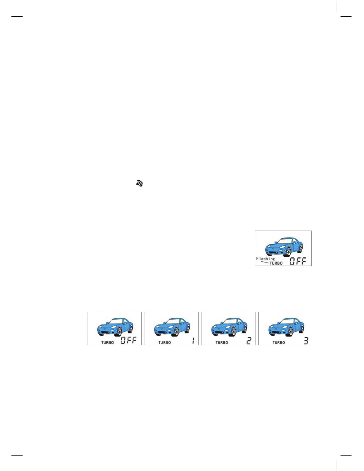
31. Turbo function
is feature is available for turbo charged vehicles that can
keep the engine running automatically for 1 min (can set to
2 min or 3 min) when engine stop the car by ignition key. In
idle status, the turbo-charged system temperature decreases
gradually to avoid high temperature, it can eectively extend
the life of the engine.
Press and hold button IV ( F ) 2 sec, then press button IV ( F ) shortly many times,
till the remote screen icon “ TURBO ” ashes.
At this time, press button I shortly or press button II shortly to select the time from
OFF, 1 min, 2 min to 3min, remote screen shows:
en press button III shortly to conrm.
Set turbo function to ON, when engine running 2 min later, pull up the hand-brake,
switch OFF ignition, the system automatically maintain the engine running for 1
min (or 2 min or 3 min). During this time, user can set arming or set disarming
many times, engine will not be stopped, if user press and hold button II 2 sec or
pull down the hand-brake, engine will be stopped.
For manual gearshi car, when set reservation mode, follow set arm and set mode
successfully, but the engine remains running, which is TURBO function working.
13
Page 17
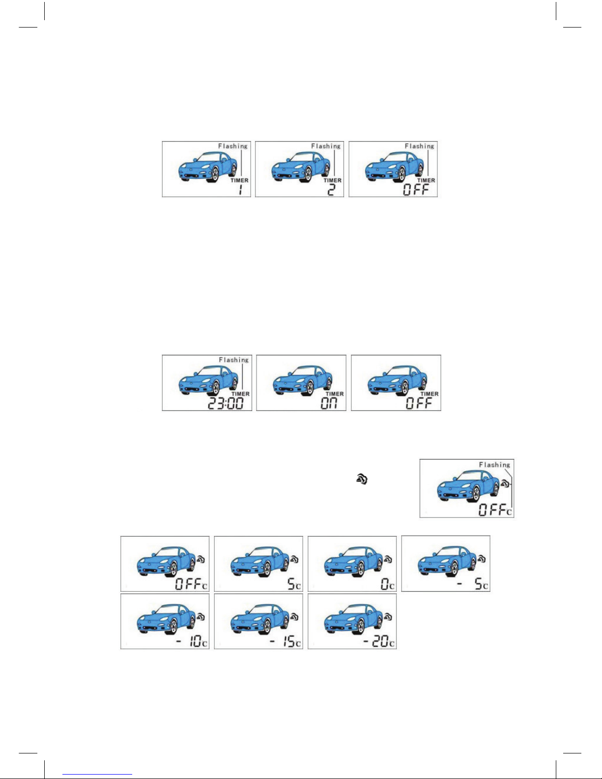
32. Timely auto start function
You can set two timely auto start time. Press and hold button IV ( F ) 2 sec, then
press button IV ( F ) shortly many times, till the remote screen icon “ TIMER 1 ”
or “ TIMER 2 ” ashes. Default setting timely auto start function is OFF, remote
screen will show “ TIMER OFF ”.
At this time, press button I shortly, it can set the auto start time, gure will increase
with step 10 min, press and hold button I, gure will add 10 continuously. Press
button II shortly, gure will decrease with step 10 min, press and hold button II,
gure will reduce 10 continuously.
If you need to set 23:00 to TIMER 1 auto start, You can press and hold button IV
( F ) 2 sec, then press button IV ( F ) shortly many times, till the remote screen icon
“ TIMER 1 ”, remote screen will show “ TIMER OFF ” , then press button I shortly
or press button II shortly, till remote screen shows “ 23:00 ”. en press button III
shortly to conrm, remote screen will show “ 23:00 ”. If you need cancel TIMER1,
you can press button III shortly again to cancel, remote screen will show “ TIMER
OFF ”.
TIMER 1 valid only once, but TIMER 2 valid day by day.
33. Low temperature auto start function
Press and hold button IV ( F ) 2 sec, then press button IV ( F )
shortly many times, till the remote screen icon “ °c ” ashes.
At this time, press button I shortly or press button II shortly to
select the time from OFF, 5°c, 0°c, –5°c, –10°c, –15°c to –20°c,
remote screen shows:
If you select the temperature –10°c, press button III shortly to conrm, then press
and hold button IV ( F ) 2 sec, remote will sound “Bi-Bi-”, it means that temperature setting is successful and exit.
14
Page 18
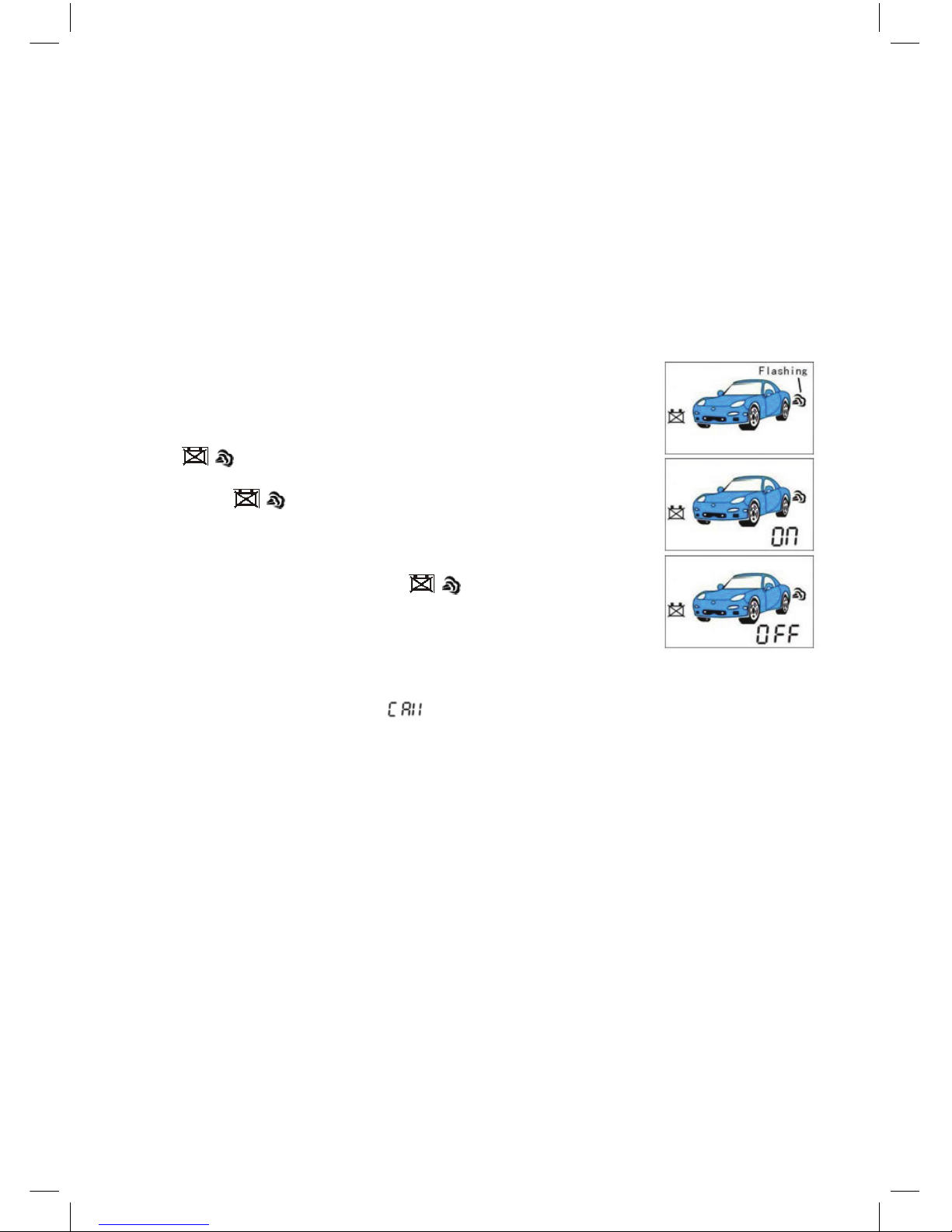
When the engine temperature below –10°c, 10 sec later engine will auto start. At
this time, engine will work 10 min continuously (user can set it to 20 min or 30
min). At this time, if temperature below –10°c, engine will auto start again.
If the temperature below 20°c aer engine start twice continuously, system will can-
cel low temperature auto start function in this anti-the cycle. Disarmed and armed
again, this function will be available.
If low temperature start is not successful, system will auto start 2 min later. If the
second start is still not successful, system will cancel low temperature auto start
function in this anti-the cycle. Disarmed and armed again, this function will be
available.
Default setting low temperature auto start function is OFF, but always valid aer
setting ON. If you don’t need this function, please set OFF.
34. Low car storage battery level auto start function
Press and hold button IV ( F ) 2 sec, then press button
IV ( F ) shortly many times, till the remote screen icon
“ ” ashes.
At this time, press button I shortly, remote sounds “Bi-”, screen
shows “ ON ”, low car storage battery level auto start
function is ON. When car battery voltage is lower than the
initialization (11.5V), engine will auto start 10 sec later.
At this time, press button II shortly, remote controller will
sound “Bi-”, screen will show “ OFF ”, low car storage
battery level auto start function is OFF.
35. Call from the car function
Press button on antenna, LED will blinks and turning light ash 3 times. At this
time, remote controller will receive CALL signal from car, buzzer will sound 25 sec
and LCD screen will show “ ” icon.
36. Revise PIN code
In disarm status,
1. Switch ON ignition,
2. Press button I + III, siren sound once, LED will be glowing continuously.
3. Enter into the rst old PIN code (press “Emergency switch” M times, M is the
rst PIN code number).
4. Switch OFF ignition, 0.5 sec later and within 2 sec, switch ON ignition.
5. Enter into the second old PIN code (press “Emergency switch” N times, N is the
second PIN code number).
6. Switch OFF ignition, 0.5 sec later and within 2 sec, switch ON ignition, if siren
sounds 3 times, PIN code will be wrong, please repeat above procedure; if siren
sounds once, PIN code will be right, please follow below procedure:
7. Enter into the rst new PIN code (press “Emergency switch” X times, X is the
rst new PIN code number).
8. Switch OFF ignition, 0.5 sec later and within 2 sec, switch ON ignition.
9. Enter into the second new PIN code (press “Emergency switch” Y times, Y is
the second new PIN code number).
10. Switch OFF ignition, 0.5 sec later and within 2 sec, switch ON ignition.
15
Page 19

11. Please repeat 7. ~ 10. procedure, enter into new PIN code again, if siren sounds
twice, new PIN code will be correct and saved; if siren sounds 3 times, system will
exit revising PIN code status, new PIN code is invalid.
Note:
1. During entering into PIN code, if user do not press “Emergency switch” within
10 sec, system will exit entering into PIN code.
2. Eective number is 1 to 9, if Pin code is wrong when entering into PIN code,
siren will sound 3 times.
3. Default setting Pin code is 11, user can revise it anytime.
4. In revising PIN code status, press I + II + III shortly, PIN code will recover to
default setting.
37. Remote controller learning
In disarm status, close the door, following below steps:
1. Switch ON ignition, if you hold the “Emergency switch”, the siren will sound
twice, turning light will ash twice.
2. Press any button of the remote controller, the turning light will ash once, the
remote controller learn successful. Learning another remote controller with same
method.
3. Aer leaning code, release the “Emergency switch”, then the new remote controller is already available but the old ones is cancelled accordingly.
Note:
Each main box can match at most 2 remote controllers. When learning the new
remote controller, the old remote controller can not be used.
38. Emergency disarm
When remote controllers lost or damaged, and you can not use remote to release
arm, Please use PIN code to release arm (enter into eective PIN code, default setting is “11”) as following:
1. Open the door.
2. Switch ON ignition.
3. Enter into the rst PIN code (press “Emergency switch” M times, M is the rst
PIN code number).
4. Switch OFF ignition and then switch ON.
5. Enter into the second PIN code(press “Emergency switch” switch N times, N is
the second PIN code number).
6. Switch OFF ignition and then switch ON.
39. Emergency set arm function
If remote is damaged, user can set arm by hand. In disarm status:
1. Turn the ignition switch from OFF to ON position, repeat 3 times and stop ON
position, siren will sound once, LED will be glowing continuously.
1. Press “Emergency switch” 8 times within 10 sec.
2. Switch OFF ignition. If setting is right, siren will sound once, and turning light
will ash once; otherwise LED will stop ash.
3. Get o the car and close the door, system enters into arm status but door will not
be locked; if do not close the door, system will arm automatically aer 30 sec later.
16
Page 20
17
Installation points to remember
is product represents many years of research and development. It is very sophisticated and should be installed by experienced security installers only. Please do not attempt
installation of this product without reading this guide. e system has been designed
to provide the ultimate in security, coupled with limitless convenience and expansion
options.
Do not disconnect the battery if the vehicle has an anti-the coded radio. If equipped
with an air bag, avoid disconnecting the battery if possible.
IMPORTANT! Many airbag systems will display a diagnostic code through their
warning light aer they lose power. Disconnecting the battery requires this code to
be erased, a procedure that can require a trip to the dealer.
Deciding on component locations
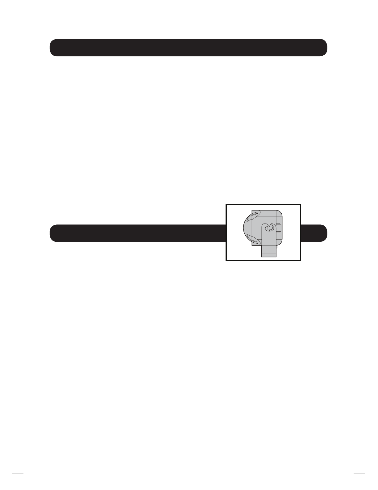
Locations for the siren
Some things to remember about mounting the siren:
• Keepitawayfromheatsources,suchasradiators,exhaustmanifolds,turbochargers
and heat shields.
• Mountitwhereathiefcannoteasilydisconnectit,whetherthebonnetisopenor
shut.
Both the siren and its wires should be dicult to nd. is usually involves
disguising the wire to look like a factory harness.
• Whenpossible,placethesirenonthesamesideofthevehicleasthecontrol
module, where its wires will reach the control module’s wires without extending
them. Always run the wires through the centre of a grommet, never through bare
metal!
• Pointthesirendownsowaterdoesnotcollectinit.
Page 21
18
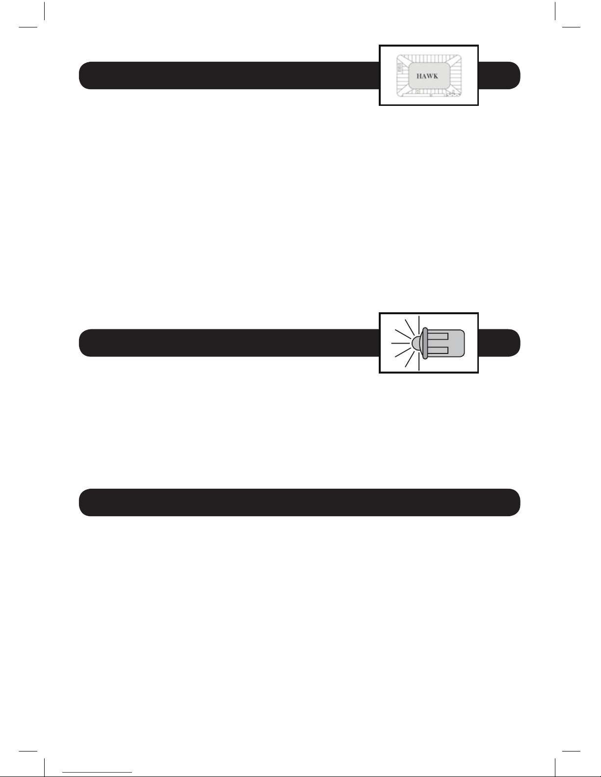
Locations for the control box
Some things to remember about where to mount the control module:
• Neverputthecontrolmoduleintheenginecompartment!
• erststepinhotwiringavehicleisremovingthedriver’ssideunder-dashpanel
to access the starter and ignition wires. If the control module is placed just behind
the driver’s side dash it can easily be disconnected.
• Whenmountingthecontrolmodule,trytondasecurelocationthatwillnot
require you to extend the harness wires. Keep it away from the heater core (or any
other heat sources) and any obvious leaks.
• ehigherthecontrolmoduleisinthevehicle,thebetterthetransmitterrangewill
be. If you put the control module under a seat or inside a metal dashboard, range
will suer.
• Somegoodcontrolmodulelocations:abovetheglovebox,insidethecentreconsole, above the under-dash fuse box, above the radio etc.
Locations for the status LED
Some things to remember when positioning the status LED:
• Itshouldbevisiblefrombothsidesandtherearofthevehicle,ifpossible.
• Itneedsatleast1/2inchclearancetotherear.
• Itiseasiesttouseasmallremovablepanel,suchasaswitchblankoradashbezel.
Remove it before drilling your 1/2 inch hole.
Locations for the Hawkguard shock sensor
Some things to remember about where to mount the shock sensor:
• Neverputtheshocksensorintheenginecompartment!
• Findaspotclosetothecontrolmodulesothatthewirestonotneedtobeextended.
Keep it away from the heater core (or any other heat sources) and any obvious leaks.
How the shock sensor is mounted is the most important factor in its performance.
We recommend 2 methods:
• Usingdouble-sidedtapeorhook-and-loopfastenertomounttoatrimpaneloran
air duct, or
• Wire-tyingtoawireharness.
Page 22
19
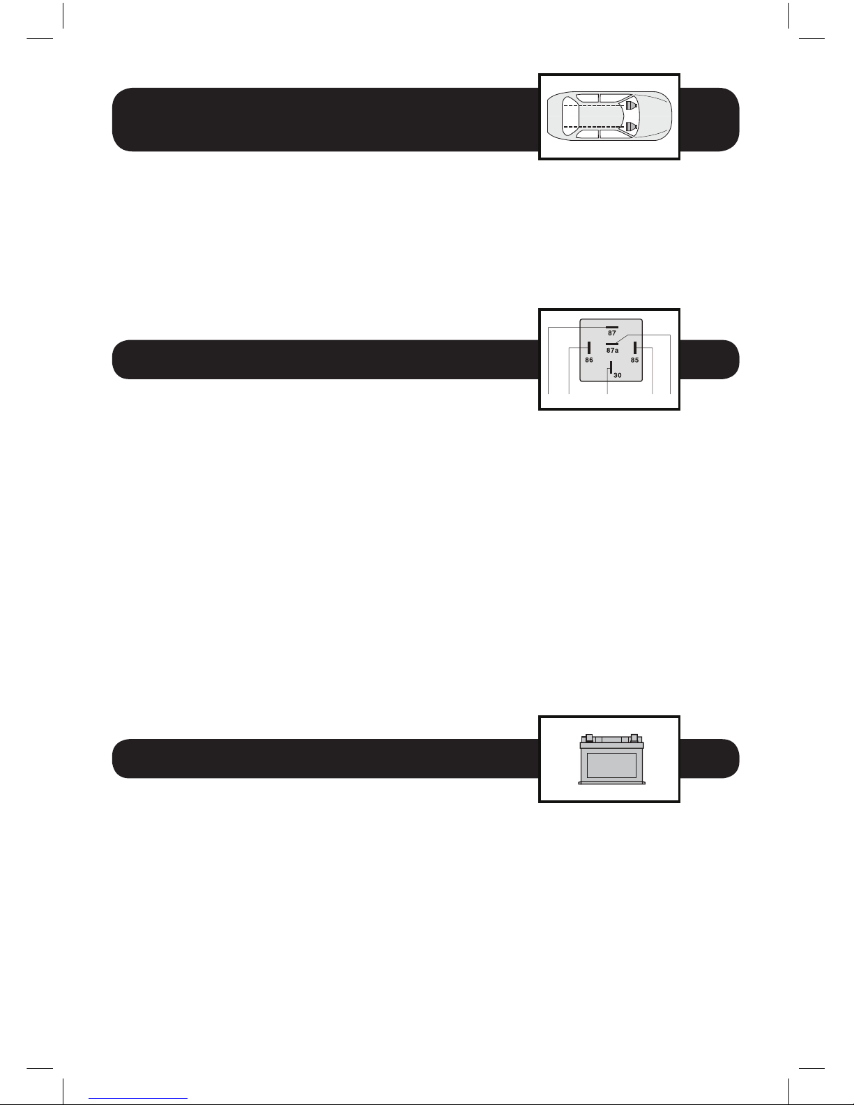
Locations for the Hawkguard
Ultra soniuc sensor
Ultrasonic cells should be placed on the le and right side as high as possible so to obtain
the best performance.
Inappropriate adjustment for the Ultrasonic sensor may let to a false alarm. To prevent
the false alarm, make sure the sensibility of ultrasonic sensor is in an appropriate degree.
An over adjustment is usually the main reason to cause false alarm.
Locations for the immobiliser relay
If Immobiliser relay or its connections are immediately visible upon removal of the underdash panel, they can easily be bypassed. Always make the relay and its connections
dicult to discern from the factory wiring! Exposed yellow butt connectors do not look
like factory parts, and will not fool anyone! For this reason, routing the immobiliser relay
wires away from the steering column is recommended.
Finding the wires you need
Now that you have decided where each component will be located, you’re going to nd
the wires in the car that the security system will be connected to:
IMPORTANT! Do not use a 12v test light to nd these wires! Use a digital multi-meter for
all testing.
Obtaining Constant 12 volts
We recommend two possible sources for obtaining constant 12 volts: the (+) terminal of
the battery, or the constant supply to the ignition switch. Always install a fuse within 12
inches of this connection. If the fuse also will be powering other circuits, such as door
locks, a power window module, headlight control system etc, fuse accordingly.
N/O COIL COIL N/CCOMMON
N/O COIL COIL N/CCOMMON
Page 23
20
Finding e 12v switched
Ignition wire
e ignition wire is powered when the key is in the run or start position. is is because
the ignition wire powers the ignition system (spark plugs, coil) as well as the fuel delivery
(fuel pump, fuel injection computer). Accessory wires lose power when the key is in the
start position to make current available to the starter motor.
How to nd (+) 12v ignition with your multi-meter:
1. Set to DCV or DC voltage (12v or 20v is ne).
2. Attach the (-) probe of the meter to chassis ground.
3. Probe the wire you suspect of being the ignition wire. e steering column harness or
ignition switch harness is an excellent place to nd this wire.
4. Turn the ignition key switch to the run position. if your meter reads (+)12v, go to the
next step. If it doesn’t, probe another wire.
5. Now turn the key to the start position. the meter display should stay steady, not
dropping more than a few tenths of a volt. If it drops close to or all the way to zero, go
back to Step 3. If it stays steady at (+) 12v, you have found an ignition wire.
How to nd starter wires 12 volts
ONLY in crank position
Testing a starter wire is very simple. Start by locating the suspected wire in the vehicle.
Next, take your meter’s black lead and connect it to ground. Next, connect the red lead to
the wire you believe is the starter wire. Crank the vehicle. e meter should ONLY show
12v when the key is in the crank position. ere should be 0 volts in all other positions.
Starter wires are used in Remote Car Starter Installations.
Using the above testing guidelines, you can test any wire. When testing an accessory like a
horn or interior light in the vehicle, simply activate the accessory with your meter leads in
place to get the meter reading. e meter should only read power and ground on accessory items when they are activated.
Page 24
21
Finding the door pin switch circuit
e best places to nd the door switch wire are:
• Atthepinswitch:whentestingthepinswitch,checkwiretoensurethatit‘sees’all
the doors. Oen, the passenger switch will cover all the doors even if the driver’s
switch will not.
• Attheinteriorlight:thismaynotbeyourbestchoiceifthevehiclehasdelayed
interior light supervision, but it will work in many Hondas, or any vehicle with
completely diode-isolated pin switches.
• Onceyouhavedeterminedthewirecolour,theeasiestplacetoconnecttothewire
is oen at the kick panel, at the windscreen pillar, or in the running board. When
an easy location is not available, running a wire to the interior light itself is oen the
best solution.
How to nd a door pin switch trigger wire with multi-meter:
1. Set to DCV or DC voltage (12v or 20v is ne).
2. In most Fords, fasten the (-) probe of the meter to chassis ground. In most other
cars,
fasten the (+) probe of your meter to (+) 12v constant.
3. Probe the wire you suspect of being the door trigger wire. If the meter reads (+) 12v
when any door is opened, you have found a trigger wire.
Making your wiring connections
ere are two acceptable ways of making a wire connection – solder connections and
crimp connectors. When properly performed, either type of connection is reliable and
trouble-free. Regardless of whether you solder your connections or you use mechanicaltype crimp on connections are mechanically sound and that they are insulated.
Cheap electrical tape, especially when poorly applied, is not a reliable insulator. It oen
falls o in hot weather. Use good quality electrical tape or heat shrink.
•Nevertwist-and-tapethewirestogetherwithoutsoldering.
•Neveruse‘fusetaps’asthecandamagefuseboxterminals.
Page 25

40. Attention for installation
H1: 6 PIN Remote start-up power socket
PIN1: Black and yellow wire – Starter switch-on wire (+12V).
It is connected to ignition lock wire where +12V appears in the “Starter” key posi-
tion. is signal means engine start-up.
PIN2: Blue wire – IGN 1 wire, output signal +12V.
It is connected to ignition lock wire where +12V appears in the “Ignition ON” key
position and does not disappear in the “Starter” position.
PIN3: Orange wire – An output signal +12V ACC – auxiliary equipment.
It is connected to ignition lock wire where +12V appears in the “ACC” and “Igni-
tion ON” key position.
PIN4: ick red wire – Remote start-up circuit power supply wire (+12V)
It is connected to ignition battery “+” terminal via 30A fuse.
PIN5: in red wire – System power supply wire (+12V)
It is connected to ignition battery “+” terminal via 3A fuse.
PIN6: Blue and red wire – IGN 2 wire, output signal +12V.
It is connected to ignition lock wire where +12V appears in the “Ignition ON” key
position and disappears in the “Starter” position.
H2: 6 PIN central lock connection socket
System has in-built power relays for central lock control. Wiring for connection of
central lock is made in a separate six-pin socket. Please refer to central lock Installation diagram.
PIN1: White wire – Central contact for central lock closing relay
PIN2: Yellow wire – Normally open contact for central lock closing relay
PIN3: Orange wire – Normally closed contact for central lock closing relay
PIN4: Orange and black wire – Normally closed contact for central lock opening relay
PIN5: Yellow and black wire – Normally open contact for central lock opening relay
PIN6: White and black wire – Central contact for central lock opening relay
H3: 8 PIN main socket 1
PIN1: No connection
PIN2: Black wire – System “–”, connect to ground (Ensure reliable contact)
PIN3: Yellow and red wire – Immobiliser bypass output (–250mA), main unit
output –250mA pulse while engine running.
PIN4: Green wire – Siren output (3A).
PIN5: Purple wire – Channel 2 output, wire for trunk release(–250mA, 0.8 sec, de-
fault setting) or windows closer(–250mA, 25 sec) or potential pulse(–250mA, 30 sec).
is function can be program setting.
PIN6: ick brown wire – Parking light output wire (7.5A)
PIN7: Yellow wire – Engine-immobiliser control wire (–250mA output aer arm-
ing system or –250mA output aer disarming system with program setting), connected to engine-immobiliser relay. Please refer to installation diagram 1 page 24.
PIN8: ick brown wire – Parking light output wire(7.5A)
22
Page 26

H4: 8 PIN main socket 2
PIN1: Brown/white wire – Negative hand-brake trigger input
PIN2: Brown/black wire – Positive foot-brake trigger input
PIN3: Gray wire – Negative trunk trigger input
PIN4: White wire – Negative door trigger input
PIN5: White/Red wire – Positive door trigger input
PIN6: Blue/black wire – Control input to start engine from outside device, the
negative pulse time is not less than 100ms.
PIN7: Blue/red wire – Engine start testing wire 1, input for engine high-voltage,
signal to be eective more than 1V. Please refer to installation diagram 2.
PIN8: Blue/white wire – Engine start testing wire 2 input for oil pressure sensor,
signal to be eective more than 6V. Please refer to installation diagram 2.
Note:
Depending on your need to install testing wire 1 or testing wire 2.
H5: Selection manual or automatic gearshi car
Selection of manual or automatic gearshi car is done using wire loop (refer to
installation diagram 2 page 25):
Keep wire loop: Manual gearshi car
Cut wire loop: Automatic gearshi car
ATTENTION:
For manual gearshi car, please do not cut the wire loop outside the main unit.
41. System parameters
1. Main unit
Working voltage: DC12V±3V
Average working current in static status: ≤20 mA
ACC output current: 25A
IGN1 output current: 25A
IGN2 output current: 25A
START output current: 25A
Turning light output current: 7.5A
Central lock output current: 15A
Siren output current: 3A
Trunk output current: –250mA
Window roll up output current: –250mA
Working frequency: 433.92MHz
2. Remote controller
Working voltage: DC1.5V
Average working current in static status: ≤1mA
Working frequency: 433.92MHz
3. Shock sensor
Working voltage: DC12V±3V
Average working current in static status: ≤2mA
23
Page 27
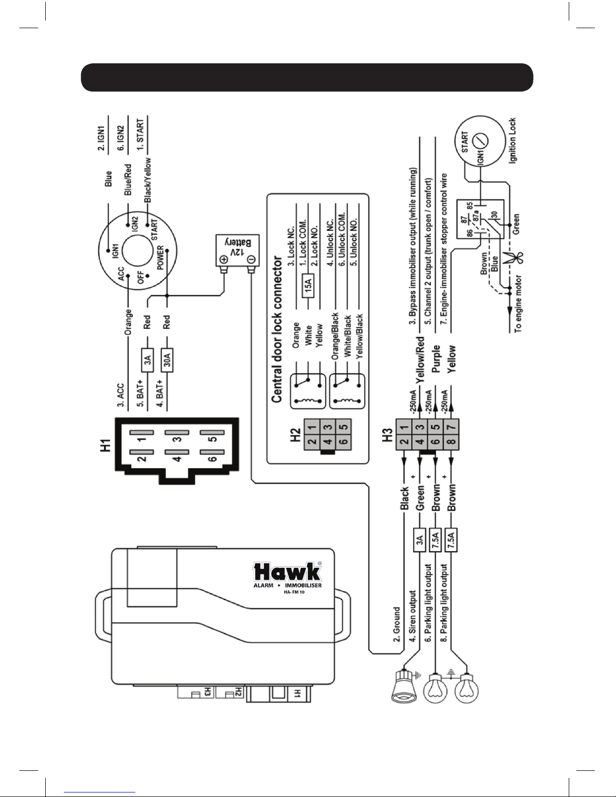
INSTALLATION DIAGRAM 1
24
Page 28
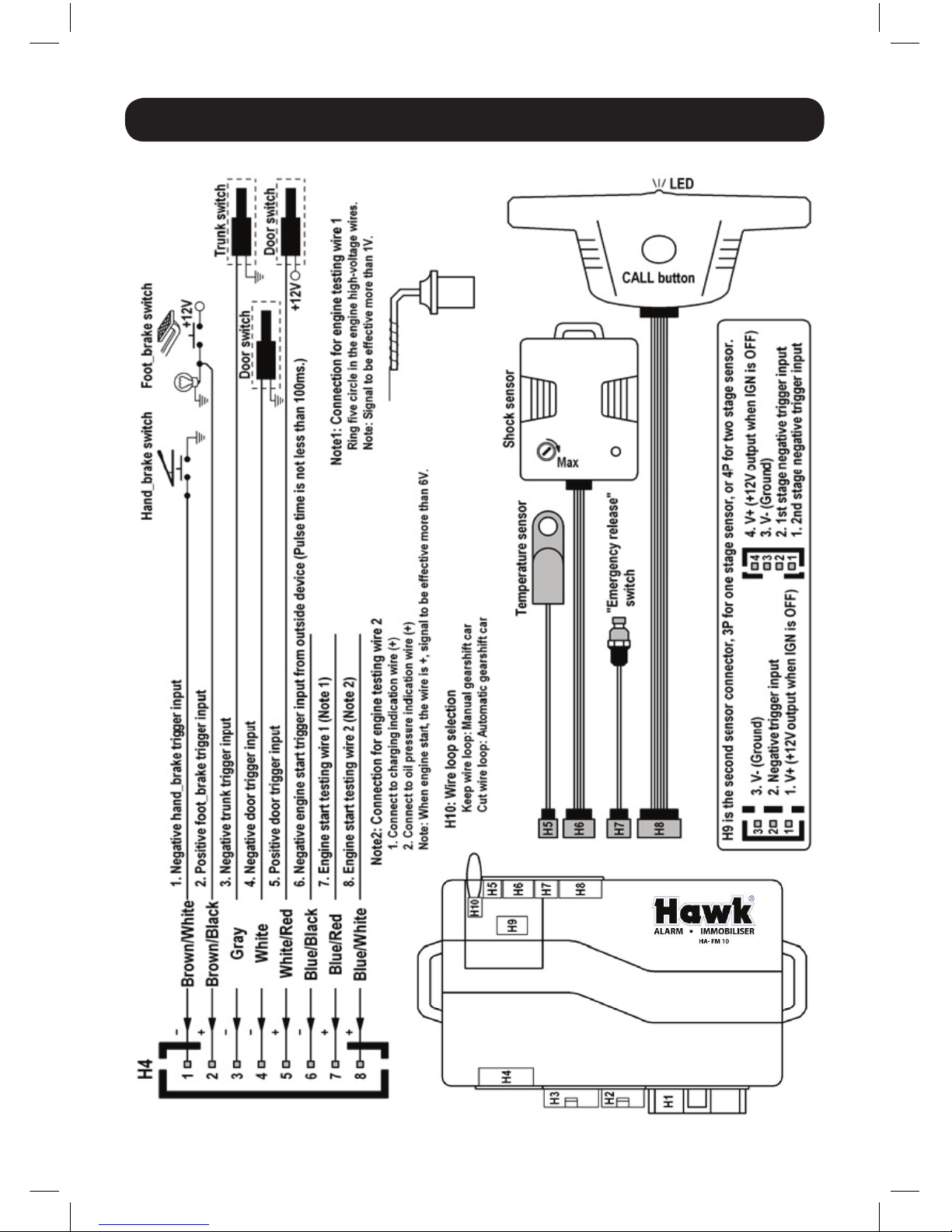
INSTALLATION DIAGRAM 2
25
Page 29
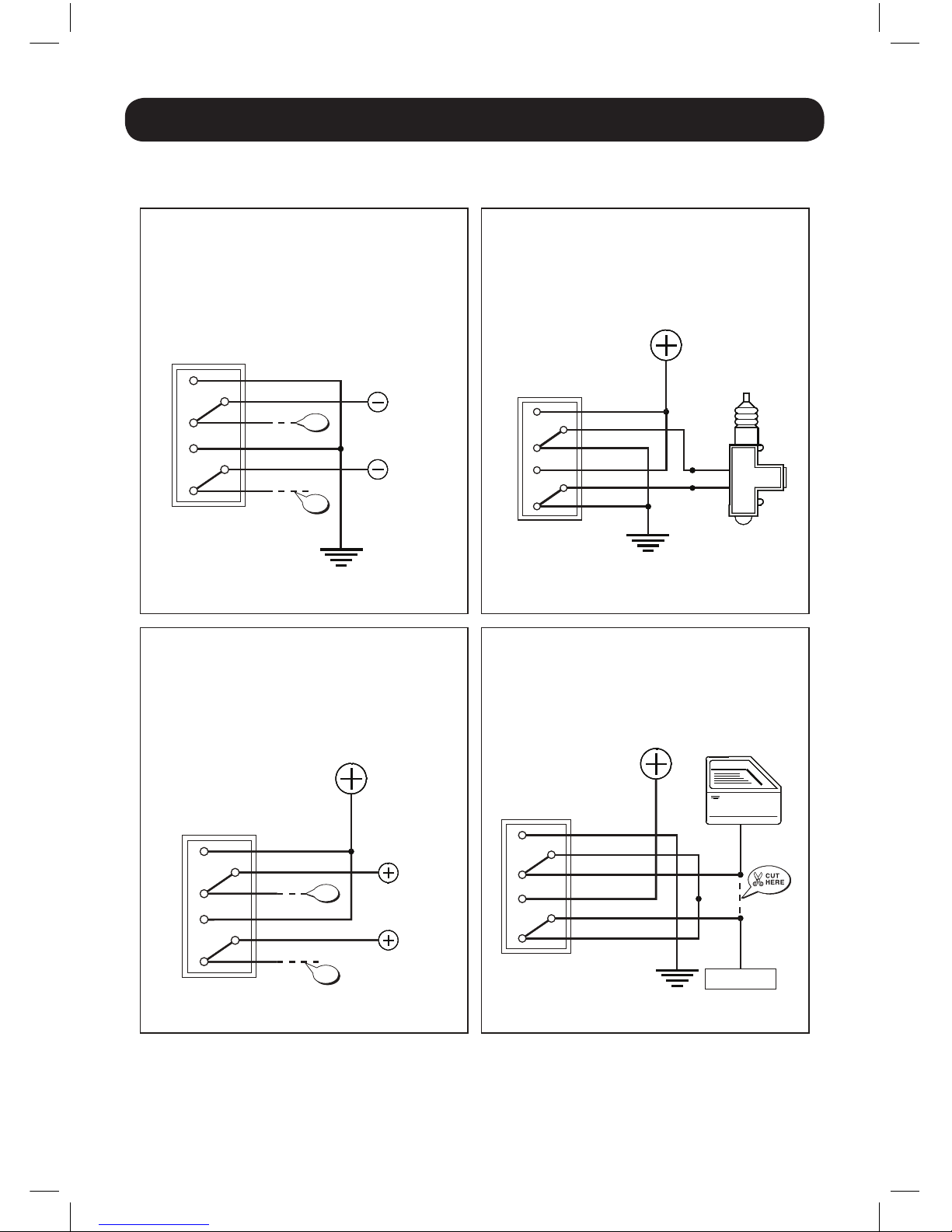
CENTRAL LOCK TECHNICAL DIAGRAM
26
Diagram A
Negative locking
Diagram B
Positive locking
Diagram C
Single point locking
Diagram D
Vacuum locking
PRIOR TO MAKING THE CONNECTION ENSURE
THE ALARM IS PROGRAMMED FOR THE
APPROPRIATE LOCKING PULSE
PRIOR TO MAKING THE CONNECTION ENSURE
THE ALARM IS PROGRAMMED FOR THE
APPROPRIATE LOCKING PULSE
PRIOR TO MAKING THE CONNECTION ENSURE
THE ALARM IS PROGRAMMED FOR THE
APPROPRIATE LOCKING PULSE
INTERNAL ALARM
RELAYS
PULSE TO
LOCK
PULSE TO
UNLOCK
GROUND
GROUND
GROUND
YELLOW
WHITE
ORANGE
YELLOW / BLACK
WHITE / BLACK
ORANGE / BLACK
PRIOR TO MAKING THE CONNECTION ENSURE
THE ALARM IS PROGRAMMED FOR THE
APPROPRIATE 3 SECOND LOCKING/
UNLOCKING PULSE
YELLOW
BLUE
GREEN
WHITE
ORANGE
YELLOW / BLACK
WHITE / BLACK
ORANGE / BLACK
INTERNAL ALARM
RELAYS
SLAVE DOOR
ACTIVATOR
INTERNAL ALARM
RELAYS
PULSE TO
LOCK
PULSE TO
UNLOCK
POSITIVE
(+12v)
YELLOW
WHITE
ORANGE
YELLOW / BLACK
WHITE / BLACK
ORANGE / BLACK
INTERNAL ALARM
RELAYS
DOOR LOCK
SWITCH
VACUUM
PUMP
YELLOW
WHITE
ORANGE
YELLOW / BLACK
WHITE / BLACK
ORANGE / BLACK
POSITIVE
(+12v)
POSITIVE
(+12v)
Central locking technical diagramsCentral locking technical diagrams
Diagram A
Negative locking
Diagram B
Positive locking
Diagram C
Single point locking
Diagram D
Vacuum locking
PRIOR TO MAKING THE CONNECTION ENSURE
THE ALARM IS PROGRAMMED FOR THE
APPROPRIATE LOCKING PULSE
PRIOR TO MAKING THE CONNECTION ENSURE
THE ALARM IS PROGRAMMED FOR THE
APPROPRIATE LOCKING PULSE
PRIOR TO MAKING THE CONNECTION ENSURE
THE ALARM IS PROGRAMMED FOR THE
APPROPRIATE LOCKING PULSE
INTERNAL ALARM
RELAYS
PULSE TO
LOCK
PULSE TO
UNLOCK
GROUND
GROUND
GROUND
YELLOW
WHITE
ORANGE
YELLOW / BLACK
WHITE / BLACK
ORANGE / BLACK
PRIOR TO MAKING THE CONNECTION ENSURE
THE ALARM IS PROGRAMMED FOR THE
APPROPRIATE 3 SECOND LOCKING/
UNLOCKING PULSE
YELLOW
BLUE
GREEN
WHITE
ORANGE
YELLOW / BLACK
WHITE / BLACK
ORANGE / BLACK
INTERNAL ALARM
RELAYS
SLAVE DOOR
ACTIVATOR
INTERNAL ALARM
RELAYS
PULSE TO
LOCK
PULSE TO
UNLOCK
POSITIVE
(+12v)
YELLOW
WHITE
ORANGE
YELLOW / BLACK
WHITE / BLACK
ORANGE / BLACK
INTERNAL ALARM
RELAYS
DOOR LOCK
SWITCH
VACUUM
PUMP
YELLOW
WHITE
ORANGE
YELLOW / BLACK
WHITE / BLACK
ORANGE / BLACK
POSITIVE
(+12v)
POSITIVE
(+12v)
Central locking technical diagrams
DON’T
USE
DON’T
USE
DON’T
USE
DON’T
USE
Page 30
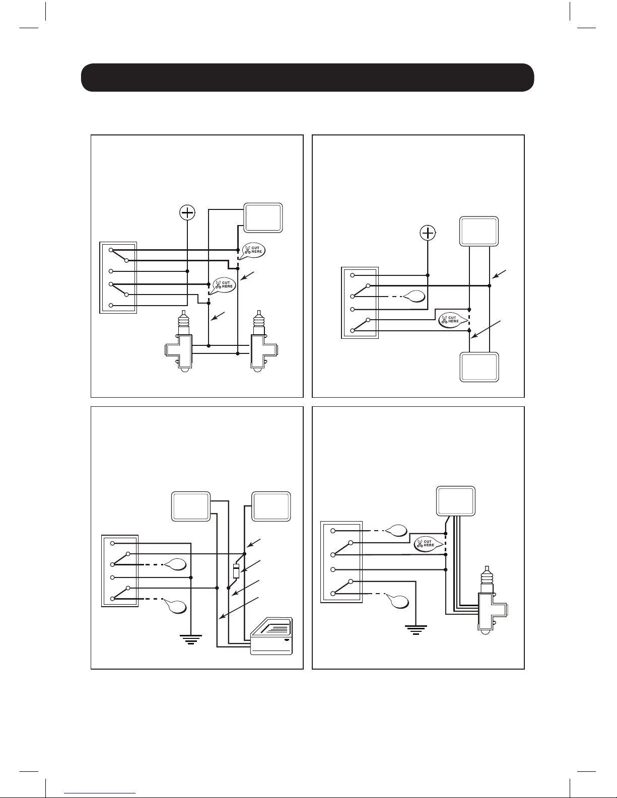
CENTRAL LOCK TECHNICAL DIAGRAM
27
Central locking technical diagrams
Diagram E
Actuator interrupt (negative at rest)
Diagram F
Negative locking with comfort closing
Vauxhall vehicles only
Diagram G
Positive locking with comfort closing
VW Golf vehicles only
Diagram H
Single wire - negative to unlock, interrupted to lock
PRIOR TO MAKING THE CONNECTION ENSURE
THE ALARM IS PROGRAMMED FOR THE
APPROPRIATE LOCKING PULSE
NOTE: NORMALLY ONLY THE
DRIVER’S DOOR ACTUATOR
NEEDS TO BE INTERRUPTED
IN THIS WAY.
NO MORE THAN 2 ACTUATORS
MUST BE CONNECTED IN THIS
WAY WITHOUT USING
ADDITIONAL 30 AMP RELAYS!
PRIOR TO MAKING THE CONNECTION ENSURE
THE ALARM IS PROGRAMMED FOR THE
APPROPRIATE LOCKING PULSE
INTERNAL ALARM
RELAYS
VEHICLE
CENTRAL
LOCKING
RELAY
VEHICLE
CENTRAL
LOCKING
RELAY
ORANGE
WHITE
YELLOW
ORANGE / BLACK
WHITE / BLACK
YELLOW / BLACK
YELLOW
ORANGE
WHITE
WHITE / BLACK
YELLOW / BLACK
ORANGE / BLACK
INTERNAL ALARM
RELAYS
GROUND
POSITIVE
(+12v)
VEHICLE
ACTIVATOR
LOCK
UNLOCK
VEHICLE
ACTIVATOR
VEHICLE
ACTIVATOR
PRIOR TO MAKING THE CONNECTION ENSURE
THE ALARM IS PROGRAMMED FOR THE
APPROPRIATE LOCKING AND COMFORT
CLOSING PULSE
YELLOW
WHITE
ORANGE
YELLOW / BLACK
WHITE / BLACK
ORANGE / BLACK
INTERNAL ALARM
RELAYS
POSITIVE
(+12v)
DRIVER’S
SIDE
DOOR
VEHICLE
CENTRAL
LOCKING
RELAY
PULSE TO
LOCK
PULSE TO
UNLOCK
DON’T
USE
PRIOR TO MAKING THE CONNECTION ENSURE
THE ALARM IS PROGRAMMED FOR THE
APPROPRIATE LOCKING AND COMFORT
CLOSING PULSES
YELLOW
WHITE
ORANGE
YELLOW / BLACK
WHITE / BLACK
ORANGE / BLACK
INTERNAL ALARM
RELAYS
GROUND
VEHICLE
ACTIVATOR
COMFORT CLOSING
CONNECTION
C
A
LOCKING
CONNECTION
UNLOCKING
CONNECTION
DIODE IN 4002
VEHICLE
CENTRAL
LOCKING
RELAY
COMFORT
CLOSING
DON’T
USE
DON’T
USE
DON’T
USE
DON’T
USE
Page 31
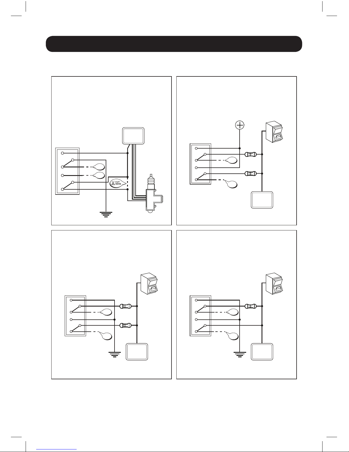
28
CENTRAL LOCK TECHNICAL DIAGRAM
Diagram I
Single wire - negative to lock, interrupted to unlock
Diagram L
Central locking control resistive negative
(type CHRYSLER VOYAGER)
Diagram M
Central locking control resistive positive
(type CHRYSLER STRATUS)
Diagram N
Central locking control resistive negative lock only
(type MERCEDES)
PRIOR TO MAKING THE CONNECTION ENSURE
THE ALARM IS PROGRAMMED FOR THE
APPROPRIATE LOCKING PULSE
PRIOR TO MAKING THE CONNECTION ENSURE
THE ALARM IS PROGRAMMED FOR THE
APPROPRIATE LOCKING PULSE
YELLOW
WHITE
ORANGE
YELLOW / BLACK
WHITE / BLACK
ORANGE / BLACK
WHITE
YELLOW
ORANGE
YELLOW
/ BLACK
WHITE / BLACK
ORANGE / BLACK
INTERNAL ALARM
RELAYS
INTERNAL
CENTRAL
LOCKING
SWITCH
INTERNAL ALARM
RELAYS
GROUND
POSITIVE
(+12v)
RESISTANCE
TO LOCK
RESISTANCE
TO UNLOCK
Central locking technical diagrams
GROUND
VEHICLE
ACTIVATOR
VEHICLE
CENTRAL
LOCKING
RELAY
VEHICLE
CENTRAL
LOCKING
RELAY
PRIOR TO MAKING THE CONNECTION ENSURE
THE ALARM IS PROGRAMMED FOR THE
APPROPRIATE LOCKING PULSE
YELLOW
WHITE
ORANGE
YELLOW / BLACK
WHITE / BLACK
ORANGE / BLACK
INTERNAL ALARM
RELAYS
INTERNAL
CENTRAL
LOCKING
SWITCH
RESISTANCE
TO LOCK
RESISTANCE
TO UNLOCK
VEHICLE
CENTRAL
LOCKING
RELAY
PRIOR TO MAKING THE CONNECTION ENSURE
THE ALARM IS PROGRAMMED FOR THE
APPROPRIATE LOCKING PULSE
YELLOW
WHITE
ORANGE
YELLOW / BLACK
WHITE / BLACK
ORANGE / BLACK
INTERNAL ALARM
RELAYS
INTERNAL
CENTRAL
LOCKING
SWITCH
RESISTANCE
TO LOCK
GROUND
VEHICLE
CENTRAL
LOCKING
RELAY
DON’T
USE
DON’T
USE
DON’T
USE
DON’T
USE
DON’T
USE
DON’T
USE
DON’T
USE
DON’T
USE
Page 32
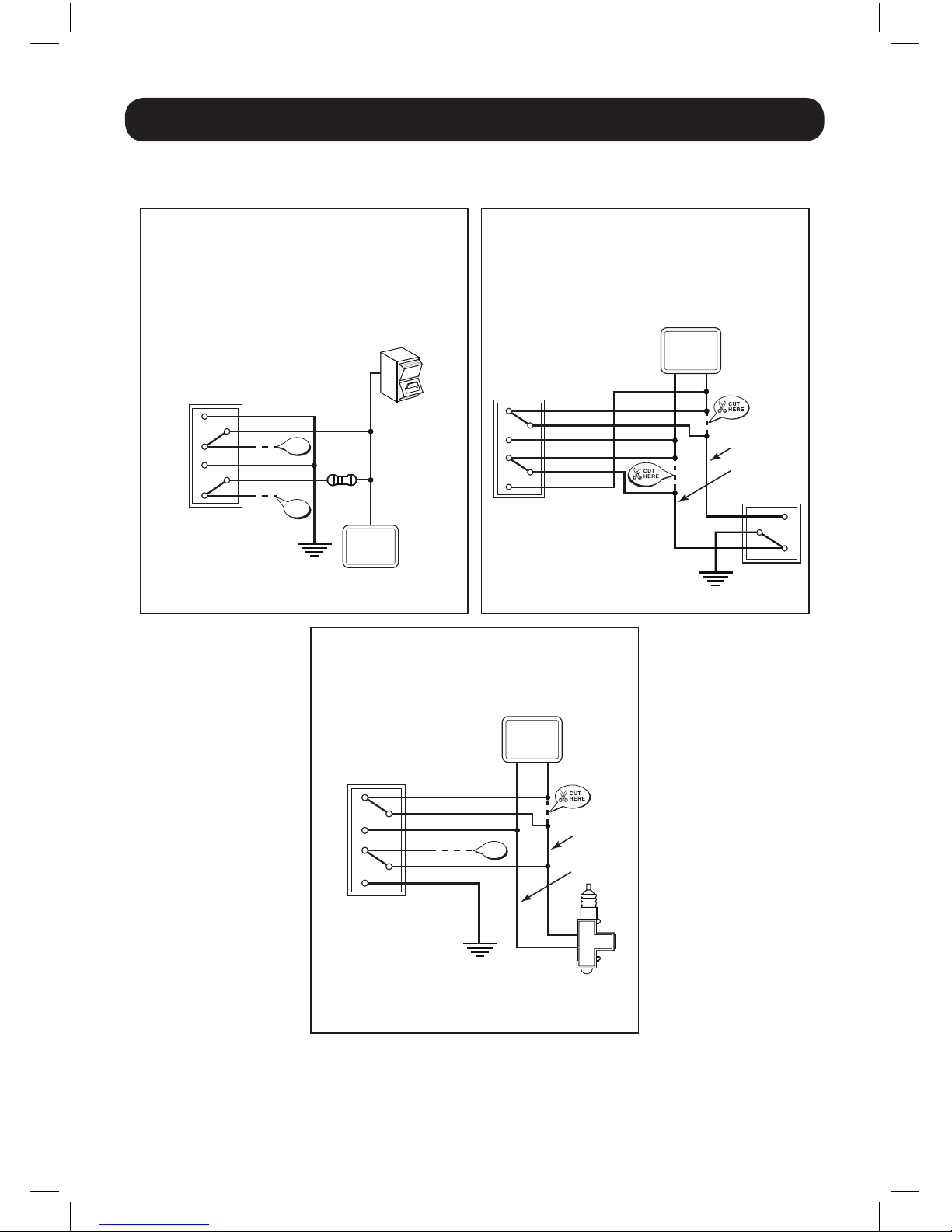
29
CENTRAL LOCK TECHNICAL DIAGRAM
Central locking technical diagrams
Diagram O
Central locking control resistive
negative unlock only
Diagram Q
Central locking control actuator switch interrupt
(negative at rest) (type Honda)
Diagram R
Central locking control negative unlock -
input switched interrupt to lock
PRIOR TO MAKING THE CONNECTION ENSURE
THE ALARM IS PROGRAMMED FOR THE
APPROPRIATE LOCKING PULSE
PRIOR TO MAKING THE CONNECTION ENSURE
THE ALARM IS PROGRAMMED FOR THE
APPROPRIATE LOCKING PULSE
PRIOR TO MAKING THE CONNECTION ENSURE
THE ALARM IS PROGRAMMED FOR THE
APPROPRIATE LOCKING PULSE
VEHICLE
CENTRAL
LOCKING
RELAY
VEHICLE
CENTRAL
LOCKING
RELAY
ORANGE
WHITE
YELLOW
ORANGE / BLACK
WHITE / BLACK
YELLOW / BLACK
INTERNAL ALARM
RELAYS
GROUND
GROUND
GROUND
VEHICLE
CENTRAL
LOCKING
ACTUATOR
YELLOW
WHITE
ORANGE
YELLOW / BLACK
WHITE / BLACK
ORANGE / BLACK
ORANGE
DOOR
ACTUATOR
SWITCH
WHITE
YELLOW
ORANGE / BLACK
WHITE / BLACK
YELLOW / BLACK
INTERNAL ALARM
RELAYS
INTERNAL ALARM
RELAYS
INTERNAL
CENTRAL
LOCKING
SWITCH
RESISTANCE
TO UNLOCK
DON’T
USE
DON’T
USE
VEHICLE
CENTRAL
LOCKING
RELAY
UNLOCK WIRE
LOCK WIRE
UNLOCK WIRE
UNLOCK WIRE
DON’T
USE
Page 33
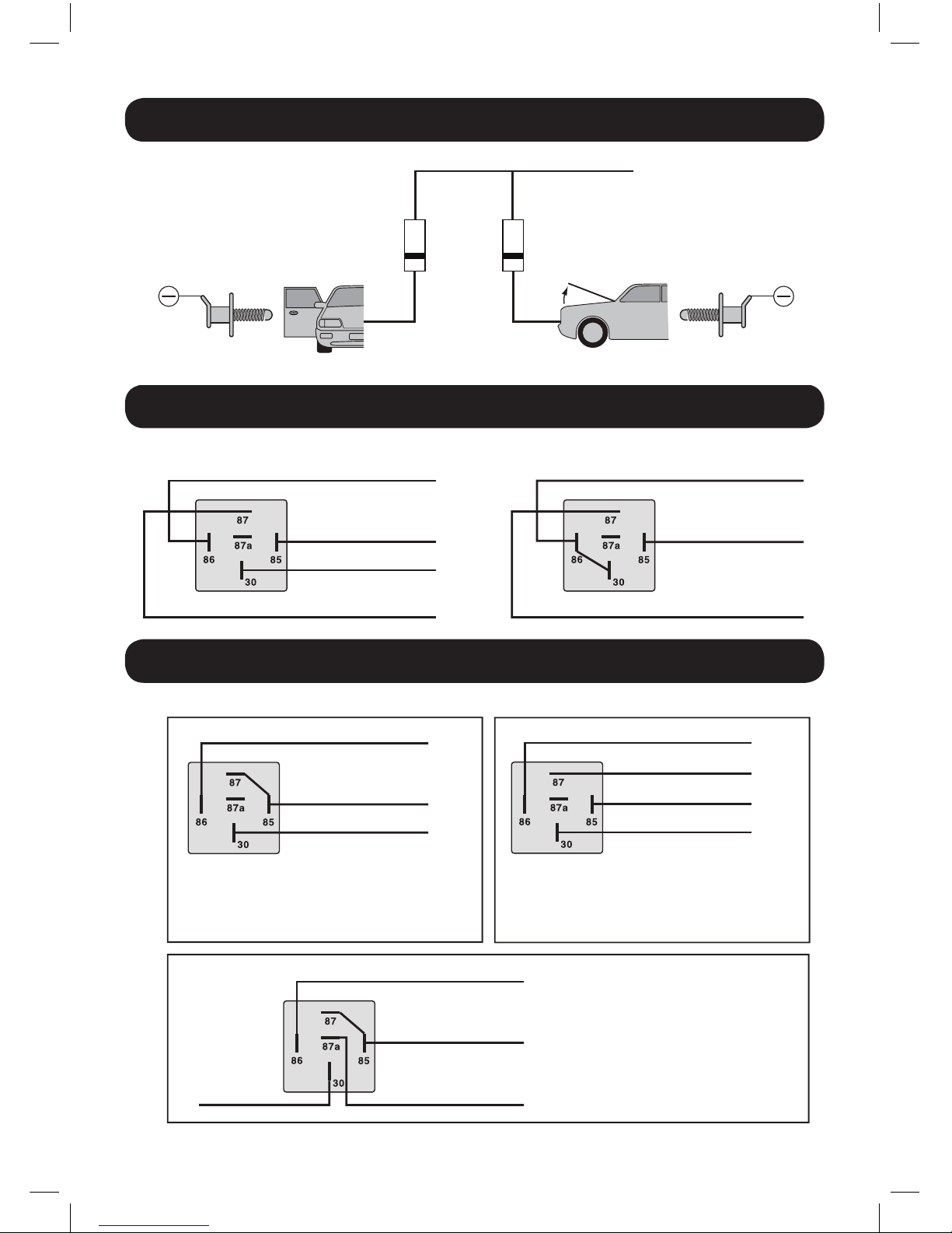
BONNET AND DOOR PROTECTION
INTERIOR LIGHT SUPERVISION RELAYS
BOOT RELEASE CONFIGURATIONS
30
Bonnet and door protection
Optional diode and
bonnet pin switch
not included
DRIVER’S PIN SWITCH BONNET PIN SWITCH
BLUE WIRE (–) INPUT FROM ALARM
1N4007 1N4007
Bonnet and door protection
Optional diode and
bonnet pin switch
not included
DRIVER’S PIN SWITCH BONNET PIN SWITCH
BLUE WIRE (–) INPUT FROM ALARM
1N4007 1N4007
Bonnet and door protection
Optional diode and
bonnet pin switch
not included
DRIVER’S PIN SWITCH BONNET PIN SWITCH
BLUE WIRE (–) INPUT FROM ALARM
1N4007 1N4007
Interior light supervision relays
Bonnet and door protection
Optional diode and
bonnet pin switch
not included
For negative interior light For positive interior light
DRIVER’S PIN SWITCH BONNET PIN SWITCH
BLUE WIRE (–) INPUT FROM ALARM
1N4007 1N4007
(-) 0v NEGATIVE CONSTANT
RED / BLACK WIRE
INPUT FROM ALARM (-)
+12v CONSTANT
TO INTERIOR LIGHT (WIRE THAT’S NEGATIVE (-) WHEN DOOR IS OPENED
)
RED / BLACK WIRE
INPUT FROM ALARM (-)
+12v CONSTANT
TO INTERIOR LIGHT (WIRE THAT’S POSITIVE (+) WHEN DOOR IS OPENED
)
Interior light supervision relays
Boot release configurations
Bonnet and door protection
Optional diode and
bonnet pin switch
not included
For negative interior light For positive interior light
Optional extra
DRIVER’S PIN SWITCH BONNET PIN SWITCH
BLUE WIRE (–) INPUT FROM ALARM
1N4007 1N4007
(-) 0v NEGATIVE CONSTANT
RED / BLACK WIRE
INPUT FROM ALARM (-)
+12v CONSTANT
TO INTERIOR LIGHT (WIRE THAT’S NEGATIVE (-) WHEN DOOR IS OPENED
)
RED / BLACK WIRE
INPUT FROM ALARM (-)
+12v CONSTANT
TO INTERIOR LIGHT (WIRE THAT’S POSITIVE (+) WHEN DOOR IS OPENED
)
+12v CONSTANT
TO BOOT RELEASE SWITCH
OR SOLENOID (+)
(-) INPUT FROM ALARM PINK WIRE
+12v CONSTANT
(-) CONSTANT GROUND
TO BOOT RELEASE SWITCH
OR SOLENOID (-)
(-) INPUT FROM ALARM PINK WIRE
This configuration is used when the vehicle’s boot release
switch operates with a 12 volt signal to the boot solenoid.
Always fuse the 12 volt supply to the relay.
This configuration is used when the vehicle’s boot release
switch operates with a high current ground output. The
ground output from your unit may not be sufficient to
trigger the switch and a relay must be added and wired in
this manner. Always fuse the 12 volt supply to the relay.
This configuration is used when the output
from the vehicle’s boot release switch rests at
ground and a 12 volt pulse cannot be applied
directly to the wire. Always fuse the 12 volt
supply to the relay.
+12v CONSTANT
TO BOOT RELEASE
SWITCH SIDE
TO BOOT RELEASE
MOTOR SIDE
(-) INPUT FROM ALARM PINK WIRE
Page 34

31
NOTES
Page 35

Consumer Warranty
Commercial Electronics (“HAWK®”) promises to the original purchaser to repair or replace
with a comparable reconditioned model any HAWK unit (hereaer the “unit”), excluding
without limitation the siren, the remote transmitters, the associated sensors and accessories,
which proves to be defective in workmanship or material under reasonable use during one year
from date of purchase, provided the following conditions are met: the unit was professionally
installed and serviced by an authorised HAWK dealer; the unit will be professionally reinstalled
in the vehicle in which it was originally installed by an authorised HAWK dealer; and the unit is
returned to HAWK, shipping prepaid with a legible copy of the bill of sale or other dated proof of
purchase bearing the following information: consumer’s name, telephone number and address;
the authorised dealer’s name, telephone number and address; complete product description,
including accessories; the year, make and model of the vehicle; vehicle license number and vehicle
identication number. All components other than the unit, including without limitation the siren,
the remote transmitters and the associated sensors and accessories, carry a one-year warranty
from the date of purchase of the same. is warranty is non-transferable altered, the unit has been
modied or used in a manner contrary to its intended purpose; the unit has been damaged by
accident, unreasonable use, neglect, improper service, installation or other causes not arising out
of defects in materials or construction. e warranty does not cover damage to the unit caused by
installation or removal of the unit. HAWK, in its sole discretion, will determine what constitutes
excessive damage and may refuse the return of any unit with excessive damage.
TO THE MAXIMUM EXTENT ALLOWED BY LAW, ALL WARRANTIES, INCLUDING
BUT NOT LIMITED TO EXPRESS WARRANTY, IMPLIED WARRANTY, WARRANTY
OF MERCHANTABILITY, FITNESS FOR PARTICULAR PURPOSE AND WARRANTY OF
NON-INFRINGEMENT OF INTELLECTUAL PROPERTY, ARE EXPRESSLY EXCLUDED;
AND HAWK NEITHER ASSUMES NOR AUTHORISES ANY PERSON OR ENTITY TO
ASSUME FOR IT ANY DUTY, OBLIGATION OR LIABILITY IN CONNECTION WITH ITS
PRODUCTS. HAWK DISCLAIMS AND HAS ABSOLUTELY NO LIABILITY FOR ANY AND
ALL ACTS OF THIRD PARTIES INCLUDING ITS AUTHORISED DEALERS OR INSTALLERS.
HAWK SECURITY SYSTEMS, INCLUDING THIS UNIT, ARE DETERRENTS AGAINST
POSSIBLE THEFT. HAWK IS NOT OFFERING A GUARANTEE OR INSURANCE AGAINST
VANDALISM, DAMAGE OR THEFT OF THE AUTOMOBILE, ITS PARTS OR CONTENTS;
AND HEREBY EXPRESSLY DISCLAIMS ANY LIABILITY WHATSOEVER, INCLUDING
WITHOUT LIMITATION, LIABILITY FOR THEFT, DAMAGE AND/OR VANDALISM. THIS
WARRANTY DOES NOT COVER LABOUR COSTS FOR MAINTENANCE, REMOVAL
OR REINSTALLATION OF THE UNIT OR ANY CONSEQUENTIAL DAMAGES OF
ANY KIND. IN THE EVENT OF A CLAIM OR A DISPUTE INVOLVING HAWK OR ITS
SUBSIDIARY, THE PROPER VENUE SHALL BE ENGLAND & WALES . THE MAXIMUM
RECOVERY UNDER ANY CLAIM AGAINST HAWK SHALL BE STRICTLY LIMITED
TO THE AUTHORISED HAWK DEALER’S PURCHASE PRICE OF THE UNIT. HAWK
SHALL NOT BE RESPONSIBLE FOR ANY DAMAGES WHATSOEVER, INCLUDING
BUT NOT LIMITED TO, ANY CONSEQUENTIAL DAMAGES, INCIDENTAL DAMAGES,
DAMAGES FOR THE LOSS OF TIME, LOSS OF EARNINGS, COMMERCIAL LOSS, LOSS OF
ECONOMIC OPPORTUNITY AND THE LIKE. NOTWITHSTANDING THE ABOVE, THE
MANUFACTURER DOES OFFER A LIMITED ONE YEAR WARRANTY TO REPLACE OR
REPAIR THE CONTROL MODULE AS DESCRIBED ABOVE.
Manufactured by Commercial Electronics. Great Britain. © Commercial Electronics 2013.
Page 36

HA - FM10
ALARM MANUAL
Manufacturer:
COMMERCIA L E LECT RONIC S
26 4 HAYDONS ROAD, WIMBLEDON, LONDON SW19 8T T. UK
TE L: +44 02 0 8404 71 05 FAX: +44 020 8 40 4 7 10 4
Manufactured by Commercial Electronics. Great Britain. © Commercial Electronics 2013.
HA - FM10
 Loading...