

Page 1
Principle of Operation
The Gladiator Acoustic Switch uses Acoustic Wave technology in a
new Sender/Receiver form for blocked chute detection. The Gladiator
Amplifier powers two Transducers which use special Hawk developed
software where both units pulse & receive each others Acoustic echoes.
When the path between the Transducers is blocked the units immediately detect the change of the return signal and trigger a communications
relay for indication or control purposes.
Hawk’s Acoustic Wave Transducers are self cleaning. The Acoustic
Switch is designed for continuous operation in dusty, wet environments
where other technologies fail. The power of each pulse (pressure wave)
blows the water, moisture & build-up off the face of the diaphragm.
Blocked Chute Detection
Quickstart
Gladiator Acoustic Switch
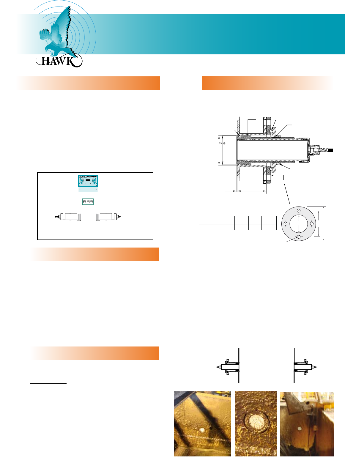
Mounting
4” FLANGE
D
A
B
C
Note: Other flange sizes available upon request.
STANDARD 4” ANSI FLANGE DIMENSIONS
FLANGE A (PCD) B (OD) C (ID) D (Hole)
TYPE mm in. mm in. mm in. mm in.
FA4 190.5 7.5 228 9.0 100 4 19 0.75
SIZE
4”
UHMW Sleeve
Threaded interface
Flange to UHMW Sleeve
100.00mm
102.00mm
95mm2.50mm
O-ring
Resin/Glue
Locking Ring
Impor tant: Mount the transducers flush with the vessel wall
or slightly (<2mm) protruding.
Transducer Setup
Gladiator Acoustic Switch transducer pairs leave the factor y
programmed as pairs (marked TD1 and TD2). A single transducer
may need to be initialised.
If your amplifier is displaying ‘error 01’ or ‘error 11’ with a
reset loop you will need to enter the advanced menu to initalise
the transducer. See the full version manual for information on
transducer initialisation.
If on power up you are prompted by the unit to ‘press cal to
initialise’ follow on screen instructions. If you are seeing ‘error
01’ or ‘error 11’ continually most likely one of the transducers
has not been initialised correctly. See the full version manual for
information on transducer initialisation.
For vessels with falling product the transducers MUST be flush
mount with the vessel wall. For heavy falling product chutes the
titanium face 15kHz version is recommended along with welding
a protective hood above each transducer (not in front of).
The transducer has a specially designed UHMW seal which must
either be per fectly in line with the vessel wall interior or slightly
(<2mm) protruded.
It should not be recessed in the vessel wall.
Pipe Specification: 4-00” Z40 ID = 100mm Black Pipe
The closest point of the mounting flange when fully screwed on
will be 95mm from the face of the transducer. Take note that
this 95mm should theoretically be the flush mount point for the
transducer face in the vessel.
Alignment - The transducers need to be as accurately facing
each other as possible. No special rotation required. ‘Alignment’
software not required.
RED
BLACK
BLUE
WHITE
RED
BLACK
BLUE
WHITE
RED
BLACK
BLUE
WHITE
AMPLIFIER
Two Acoustic Switch Remote Transducers with
UHMW flush mount sleeve & FA4A-4 flange mount.
JUNCTION BOX
Min. 400mm
Cable Extension
If using a cable run or extending the Hawk supplied cable use
Belden 3084A cable. Hawk supplies lengths of this cable. For
customer supplied cable junction boxes seperate the shield
cable at the terminals of the junction box. The shield should
only have one ground point through the cable run which is the
Gladiator amplifier ‘black’ terminal along with the black wire as
per the cable which is potted to the Transducers.
It is preferable to have no extra connection points between the
Transducers and the Hawk supplied junction box. Transducers
can be ordered with 50m potted cable.
Page 2
Contact
Hawk Measurement Systems Australia
Phone: +61 3 9873 4750
[email protected]
Hawk Measurement US
Phone: +1 888 429 5538
[email protected]
For global representatives:
www.hawkmeasure.com
Part number: DOC-GASBC-QUICK
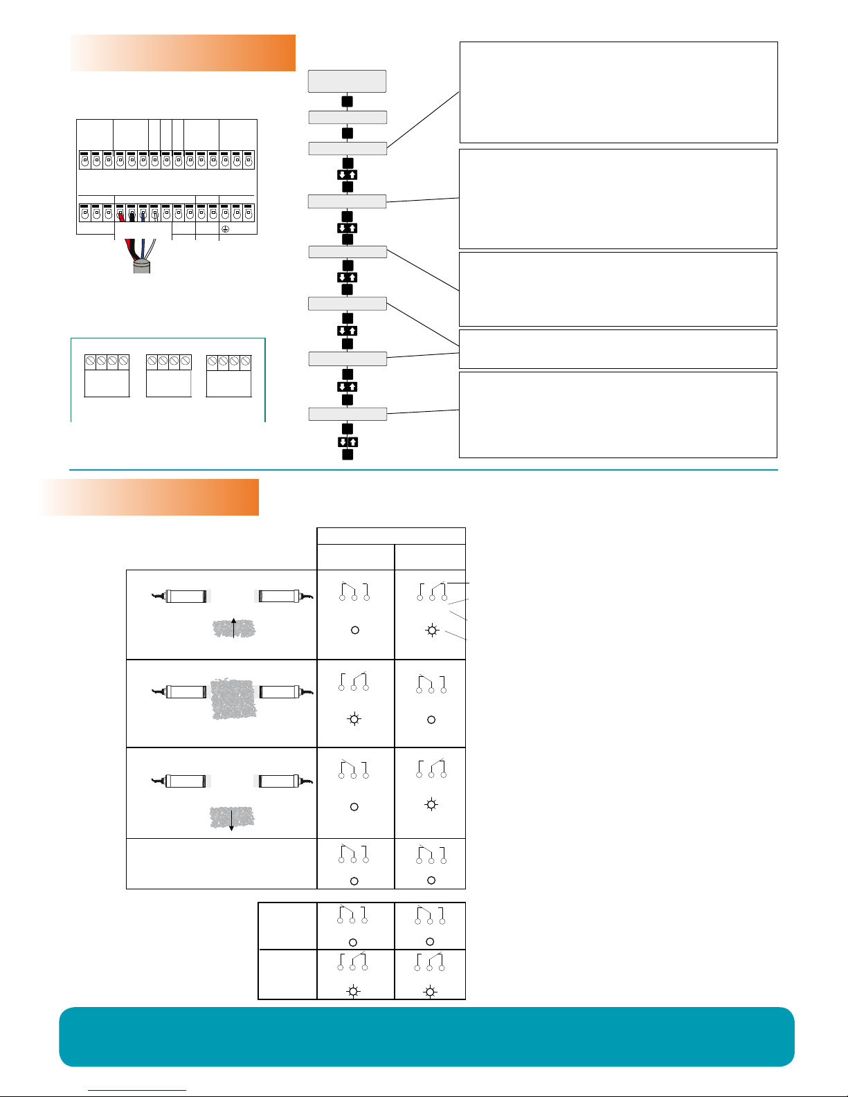
FailSafe Switch Contact Action
Relay 2
Setup Procedure
Contact Action
Relay Functions
Selec t the Switch point
The output relay will switch at the entered % value. The default value of 76% will be
suitable for detecting most media. For detection of lighter / fine products select a lower
% value and vic e versa. For heavy materials a higher % setting may be required. When
the level or target falls below the sensors the relay will switch back on.
If product constantly falls in the sensor path choose a higher %.
Selec t the Switch Time Delay
Set the delay time for the relay switching on and of f. If produc t constantly falls in
front of the sensor path allow a few seconds for O N delay.
Mounting
Do not proc eed with this step unless the material or target position is well beneth
the line bet ween the sender and receiver.
Select ‘ Yes’ to start the mounting c alibration. ‘Wait’ will be displayed dur ing the
calibration for up to 3 0 seconds. Unit is now able to cancel the inf luence of the
mounting. The % reading on the back lit display has been zeroed with the existing
proces s conditions and the measurement histor y log has been cleared.
Always CAL MOUNT after changing application type or moving the transducers.
Selec t the required r elay action
The Relay action can be defaulted to either ‘ON’ or ‘OFF’ and switch ‘ON’ or ‘OFF’
in response to an instr ument failure.
Failsafe High - Relay is energised during normal operation and de-energised
during blocked conditions or unit failure.
Failsafe Low - Relay is de -energised dur ing normal operation and energised
during blocked conditions or unit failure.
Choose Applic ation Type
Alignment - Not used
Blocked Chutes - Configures the unit for blocked chute applications.
Boom Protection - Not used
Other - If you have a light /low dielectr ic
material w hich is failing to switch select this
mode and enter a low or lower sens. % value.
Note: If prompted to ‘re -calc app params’ this means you have already sele cted
Blocked Chute mode and the unit is asking if you wish to re- conf igure the settings..
QuickSet
Cal Mounting
Relay Action
Unlock
0
App Type
CAL
CAL
CAL
CAL
CAL
CAL
CAL
CAL
CAL
CAL
RUN
Switch Point
CAL
On Delay Adj
OffDelay Adj
CAL
CAL
1 2 3
1 2 3
1 2 3
1 2 3
1 2 3
1 2 3
1 2 3
1 2 3
Material level rising
Material detected
NC NO
NC NO
NC NO
NC NO
NC NO
NC NO
NC NO
NC NO
COM COM
COM COM
COM COM
COM COM
POWER FAILURE
NC NO NC NOCOM COM
INTERNAL FAILURE
POWER FAILURE
OR
SYSTEM OPERATING
NORMALLY
NC NOCOM
NC NOCOM
State 1State 2State 3
Smart Integral
Receiver terminal
numbers
Remote Amplifier
terminal function
labels
FailSafe Low
FSL
FailSafe High
FSH (default)
Relay Status
LED Status
Relay Action
Material level falling
AC-IN
A
L1
+
–
DC-INCOMMSSENSOR
N
B
RELAY 2
NC
COM
NO
RED
BLACK
BLUE
WHITE
12-30VDC
90-260 VAC
RELAY 1
NC
COM
NO
TEST IN
SLAVE IN
MASTER OUT
BROWN
CURRENT
+
–
Is
Relay 1 - Output Relay
Relay 2 - FailSafe Relay
WIRING
HAWK JUNCTION BOX
AC-IN
A
L1
+
–
DC-INCOMMSSENSOR
N
B
RELAY 2
NC
COM
NO
RED
BLACK
BLUE
WHITE
12-30VDC
90-260 VAC
RELAY 1
NC
COM
NO
TEST IN
SLAVE IN
MASTER OUT
BROWN
CURRENT
+
–
Is
Relay 1 - Output Relay
Relay 2 - FailSafe Relay
TRAN SDUCE R 1
TRAN SDUCE R 2
AMPLI FIER
Connect colour to colour
To Junction Box
RED
BLACK
BLUE
WHITE
RED
BLACK
BLUE
WHITE
RED
BLACK
BLUE
WHITE
Use CAL as select / proceed
Use RUN as back / cancel
Arrows to scroll between menu options
 Loading...