

Hawk gladiator, Gladiator AS2000, Gladiator GARP, Gladiator AS2100, Gladiator AS2200 Instruction Manual
...Page 1

INSTRUCTION MANUAL
Admittance Smart Switch Series
- An all-round point level switch
-
A higher level of performance
Page 2

1
Sultan 234 Series
Admittance Smart Switch Series
Manual
Rev 1.2, June 2008
PROPRIETARY NOTICE
The information contained in this publication
is derived in part from proprietary and patent
data. This information has been prepared for
the express purpose of assisting operating and
maintenance personnel in the efcient use of
the instrument described herein. Publication of
this information does not convey any rights to
use or reproduce it, or to use for any purpose
other than in connection with the installation,
operation and maintenance of the equipment
described herein.
WARNING
This instrument contains electronic components
that are susceptible to damage by static
electricity. Proper handling procedures must
be observed during the removal, installation, or
handling of internal circuit boards or devices:
Handling Procedure:
1. Power to unit must be removed prior to
commencement of any work.
2. Personnel must be grounded, via wrist strap
or other safe, suitable means, before any
printed circuit board or other internal devices
are installed, removed or adjusted.
3. Printed circuit boards must be transported
in a conductive bag or other conductive
container. Boards must not be removed from
protective container until the immediate time
of installation. Removed boards must be
placed immediately in a protective container
for transport, storage, or return to factory.
Comments:
This instrument is not unique in its content
of ESD (electrostatic discharge) sensitive
components. Most modern electronic designs
contain components that utilize metal oxide
technology (NMOS, CMOS, etc.). Experience
has proven that even small amounts of static
electricity can damage or destroy these
devices. Damaged components, even though
they appear to function properly, exhibit early
failure.
General Description
Features 2
Typical Applications 3
Dimensions 5
Mounting 9
Flexile Cable Probe Adjustment 11
Wiring
- Smart Probe 12
- Remote Probe 13
- Relay Functions 14
- Multidrop Connections 15
- HawkLink GSM 16
- Test Terminal 18
Smart Probe Setup Procedure 19
Remote Setup Procedure 22
Remote Software Menu 24
- Software Tree 25
- QuickSet 26
- Advanced Menu 27
- Diagnostic Displays 30
Multidrop Communication 32
Remote Communication 33
Troubleshooting 34
Part Numbering 35
Specications 37
Dielectric Constant 38
CE Declaration 39
Contact Information (back cover)
INTRODUCTION
CONTENTS
Page 3
2
Admittance Smart Switch Series
Manual
Rev 1.2, June 2008
3
GENERAL DESCRIPTION
The Gladiator Smart Admittance Switch
is a third generation, state-of-the-art
level probe, designed to operate in
tough industrial environments. The
probe of the Admittance Switch forms
one plate of a capacitance circuit, with
the vessel wall making the second plate.
The dielectric constant of the product
between the probe and the vessel wall
will cause a capacitive change as the
level approaches the probe, and the
output will switch in response. A special
circuit is used to ignore product build-up
between the sensing probe (active element) and guard, and also between the
guard and vessel wall. The output has
adjustable hysteresis and delays for ‘on’
or ‘off’ switching.
A test function is available to remotely
conrm the probe integrity by switching
the relay contacts.
The Gladiator Smart Switch Series
includes communications capability for
remote adjustment, control and monitoring.
Principle of Operation
The dielectric constant of the material
in the vessel will be different to that of
air. When the material comes near or in
contact with the probe an admittance
change will occur. The resonant frequency of the internal oscillator will then
change. The relay will switch when the
frequency reaches the user selected
Switch Point value.
Excellent immunity to product build-up
Excellent temperature stability - no
false trips
Simple ‘1-minute’ set-up
Relay outputs: Smart probe (1)
Remote (2)
Remote test function
Adjustable ON and OFF delays (0-20 sec)
Smart communication options:
GosHawk, Modbus,
HART, Probus
DP, DeviceNet
Remote GSM Connection option
Remote amplier to probe separation
up to 500 m (1640 ft)
Bright visual status indication on
Probe
LCD Diagnostic for Remote version
Independant housing alignment after
mounting thread locked
Non contact switching possible with
many materials
•
•
•
•
•
•
•
•
•
•
•
•
•
FEATURES
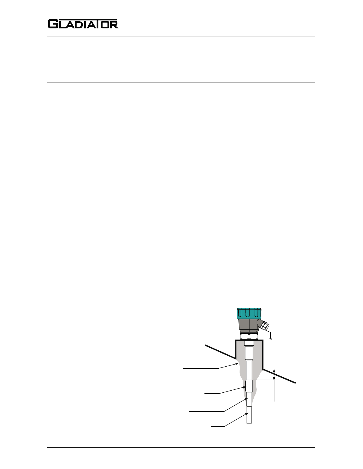
Probe
Probe Insulation
Guard
Material build up
> 100mm
Ground the housing to
vessel, if vessel is metallic.
Ground the housing to
plant ground, if vessel is
non-metallic.
Page 4
3
Sultan 234 Series
Admittance Smart Switch Series
Manual
Rev 1.2, June 2008
TYPICAL APPLICATIONS
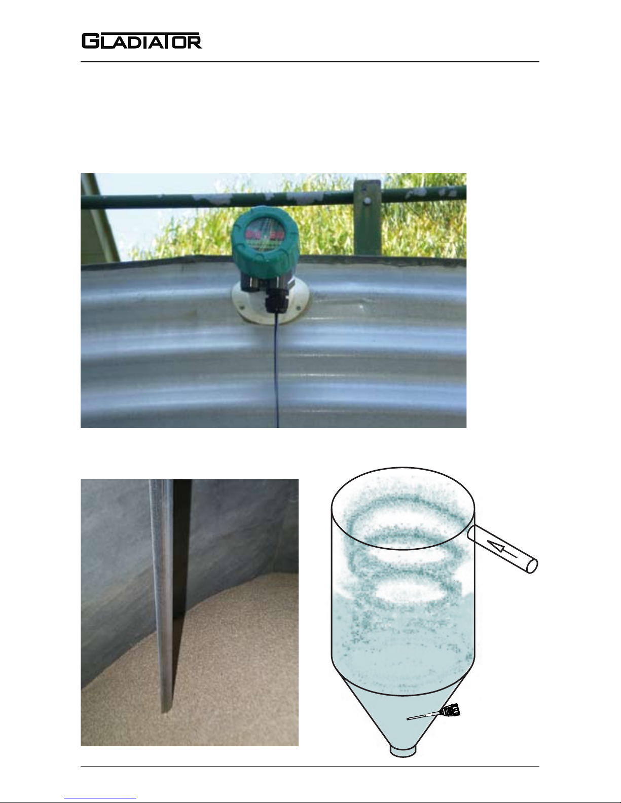
High level switch in grain application
Cyclone bin level switch
High level switch in plastic pellet silo
Page 5
4
Admittance Smart Switch Series
Manual
Rev 1.2, June 2008
5
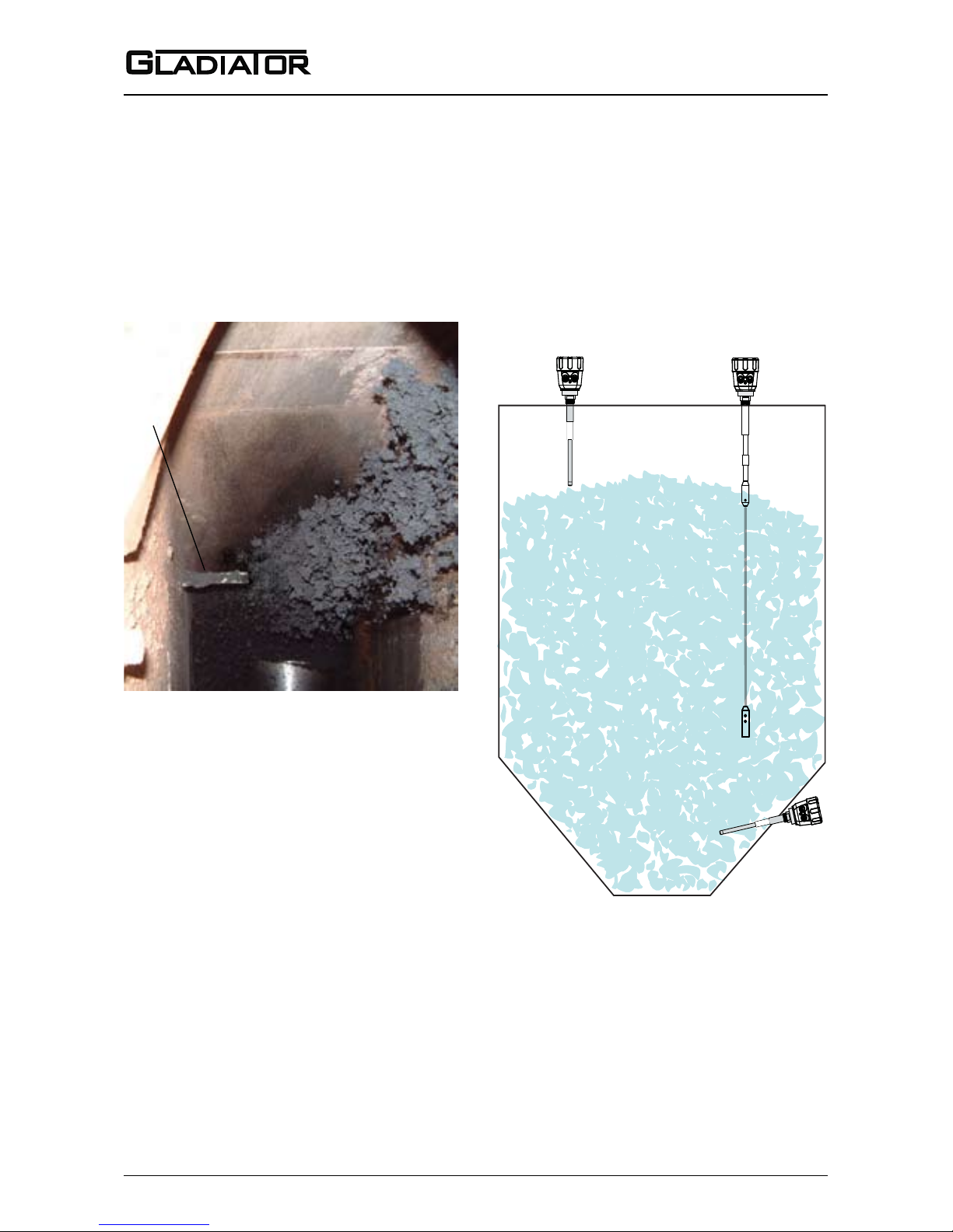
Continuous lling with build-up
on probe
High and low level switch in a hopper
If impact from falling material is
expected, mount a protection plate
above the probe to ensure no
physical damage can occur to the
probe in normal operation. If it is not
possible to do this or to move the
probe to an alternative position, use
a microwave switch.
See www.hawkmeasure.com for
further information on Microwave
switches and other level products.
TYPICAL APPLICATIONS
Probe
Low level
(side mounted)
Low level
(top mounted)
High level
(top mounted)
Page 6
5
Sultan 234 Series
Admittance Smart Switch Series
Manual
Rev 1.2, June 2008
83mm (3.3”)
76.5 (3”)
61mm (2.4”)
8mm (0.3”)
106mm (4.2”)
106mm (4.2”)
10mm (0.4”)
151mm (5.9”)
145mm (5.7”)
38mm (1.5”)
160mm (6.3”)
192mm (7.6”)
166mm (6.5”)
142mm (5.6”)
10.5mm (0.4”)
3 x 20mm (0.7”), 1x16mm (0.6”)
Knock outs
166mm (6.5”)
192mm (7.6”)
160mm (6.3”)
Front Side Back
DIN Rail Mounting
(clips included)
DIMENSIONS
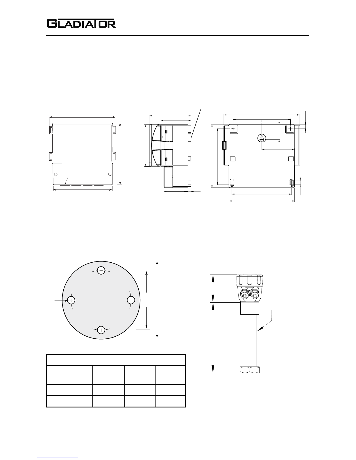
REMOTE AMPLIFIER ENCLOSURE
X mm
temperature
extension
SS 316
X mm:
Max. 80ºC (176ºF) ~ no temperature extension required.
Max.150ºC (302ºF) ~ 150mm (5.9”)
Max. 250ºC (482ºF) ~ 250mm (9.8”)
For the 450ºC (842ºF) Probe, a different extension applies.
165mm (6.5”)
125mm (4.9”)
4x18mm (0.7”) holes
90mm (3.5”)
HIGH TEMPERATURE
EXTENSIONS (<250°C, <482°F)
Remote Probe or Smart Probe
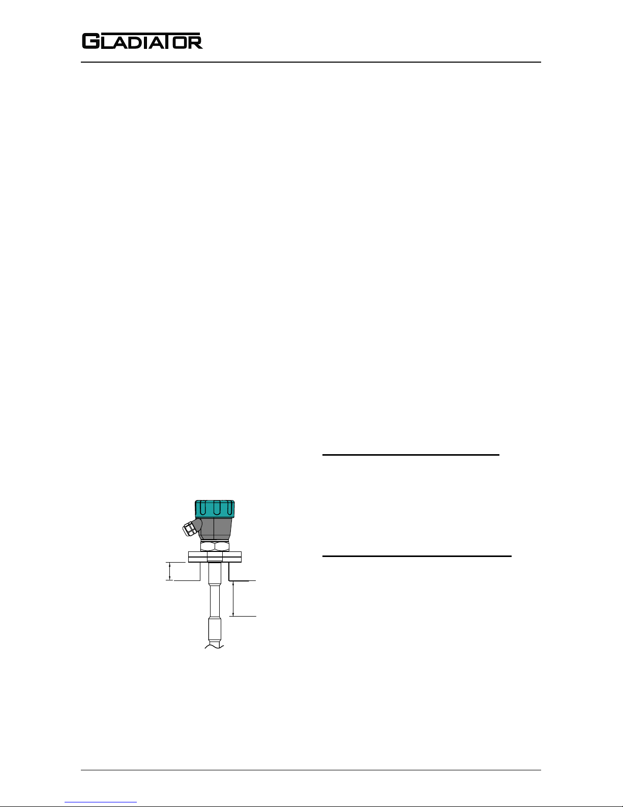
OPTIONAL FLANGE
Flange Dimensions - 50mm (2”)
ANSI (Class 150)
A
120.7 4.75”
B
152.4 6”
C
19.1 0.75”
DIN (PN40)
125 4.9” 165 6.5” 18 0.7”
JIS (10K)
120 4.7” 155 6.1” 19 0.75”
A B
C
Page 7
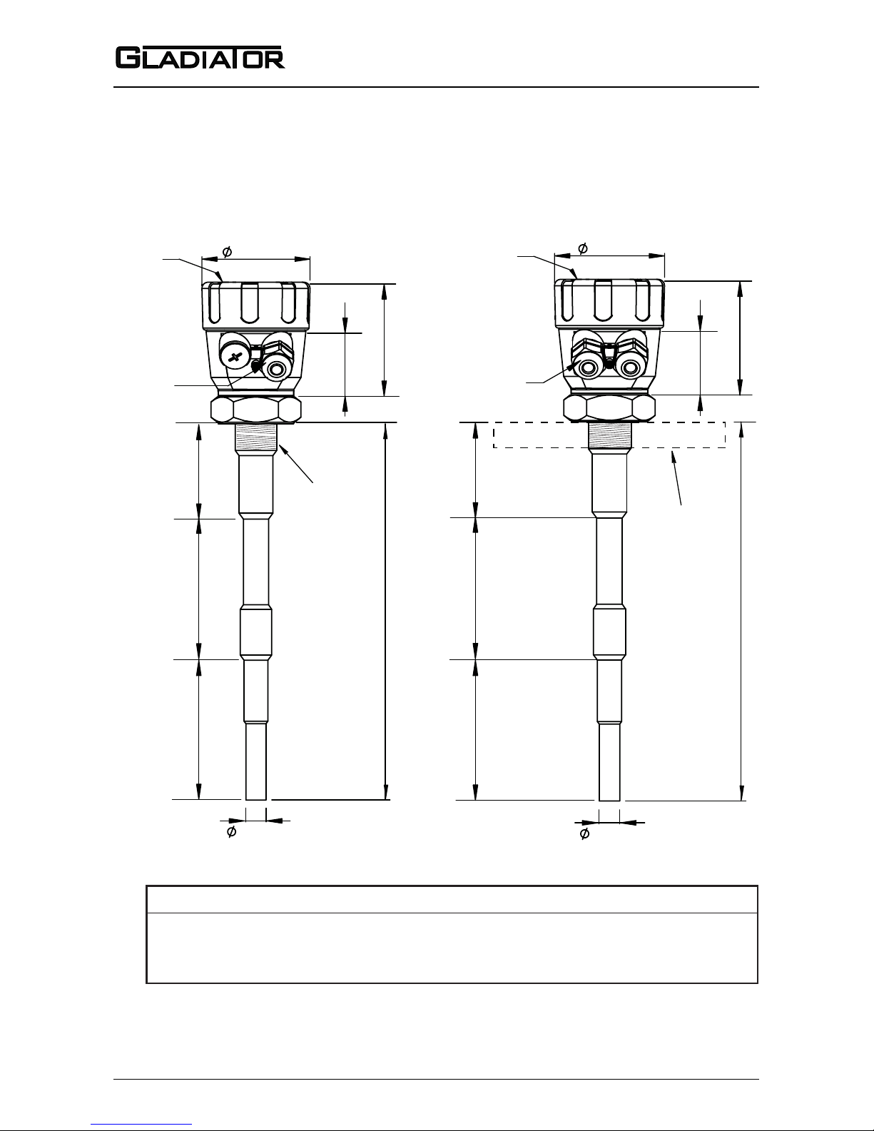
6
Admittance Smart Switch Series
Manual
Rev 1.2, June 2008
7
Probe Length (mm, inch) Active + Guard + Ground
= 50mm, 2”
= 250mm, 9.8”
P30 (300mm,11.8”)
P50 (500mm, 19.7”)
= 750mm, 29.5”
P100 (1000mm, 39.4”)
250mm, 9.8”
250mm, 9.8”
250mm, 9.8”
+
+
+
Ground 100mm (3.9”)Guard 150mm (5.9”)Active (mm)
85mm (3.3”)
probe length
M20 cable gland
or 3/4” NPT adaptor
Window for
viewing status
LEDs
Mounting
thread
90mm (3.5”)
50mm (2”)
16mm (0.6”)
Ground 100mm (3.9”)
Guard 150mm (5.9”)Active (mm)
85mm (3.3”)
probe length
Window for
viewing status
LEDs
Optional Flange
90mm (3.5”)
50mm (2”)
2 x M20
cable glands
or 3/4” NPT adaptors
16mm (0.6”)
DIMENSIONS
REMOTE PROBE SMART PROBE
Page 8
7
Sultan 234 Series
Admittance Smart Switch Series
Manual
Rev 1.2, June 2008
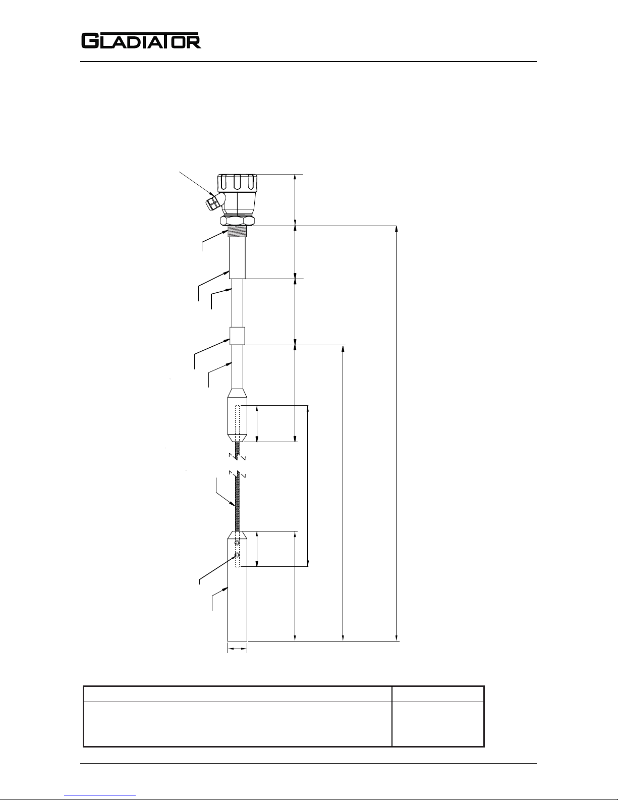
DIMENSIONS
FLEXIBLE CABLE PROBE
M20 x 1.5
or 3/4” NPT adaptor
115mm
Cable Length (mm, inch) Active + Guard + Ground (Rope Length)
C100 (1000mm, 39.3”) = 750mm, 29.5” + 250mm, 9.8” 451mm, 17.8”
C200 (2000mm, 78.7”) = 1750mm, 68.9” + 250mm, 9.8” 1451mm, 57.1”
C300 (3000mm, 118.1”) = 2750mm, 108.3” + 250mm, 9.8” 2451mm, 96.5”
SS 316
Removable grub screws
for cable adjustment
Ø 8mm (0.3”)
SS 316
Teflon
SS 316
Teflon
SS 316
100mm (3.9”)
Ground
150mm (5.9”)
Guard
Rope
250mm (9.8”)
Weight
Active
Cable Length
Mounting Thread
(1.5” NPT or BSP only)
Ø 40mm (1.6”)
83mm (3.3”)
83mm (3.3”)
215mm (8.4”)
Page 9
8
Admittance Smart Switch Series
Manual
Rev 1.2, June 2008
9
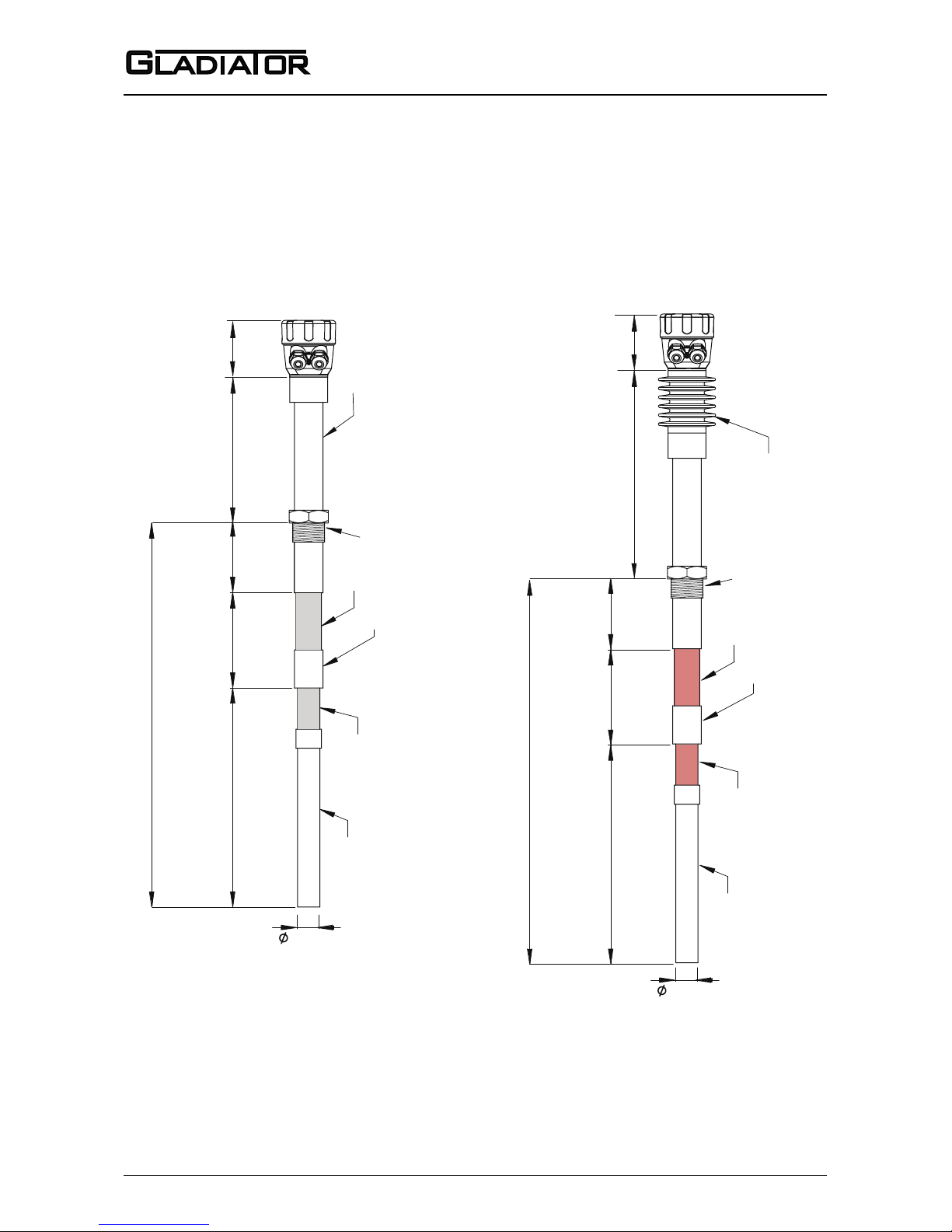
DIMENSIONS
HIGH TEMPERATURE PROBES
HIGH TEMP PROBE (<250°C, <482°F) HIGH TEMP PROBE (450°C, 842°F)
Probe length
150mm
(5.9”)
Guard
Active
Element
Temperature extension
100mm
(3.9”)
Ground
Teflon
Teflon
Max 150ºC (302ºF)
Max 250ºC (482ºF)
SS 316
SS 316
SS 316
16mm (0.6”)
Mounting Thread
Ø90mm (3.5”) L100mm (4”)
Aluminium heat sink
Ceramic
Ceramic
Max 450ºC (842ºF)
SS 316
SS 316
36mm (1.4”)
329mm (13”)
Probe length
150mm
(5.9”)
Guard
Active
Element
100mm
(3.9”)
Ground
Mounting Thread
(1.5” NPT or BSP only)
90mm (3.5”)
90mm (3.5”)
(See page 5 for
temperature ex tension
options)
Page 10
9
Sultan 234 Series
Admittance Smart Switch Series
Manual
Rev 1.2, June 2008
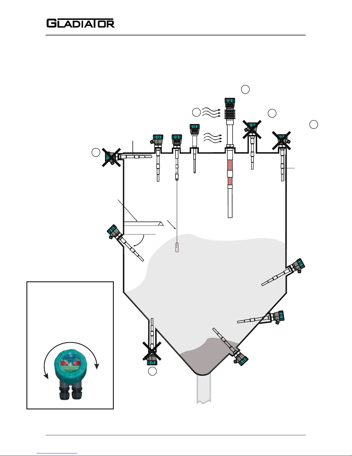
MOUNTING
Probes can be mounted from the top,
side and bottom.
Points to consider when mounting:
A. Material Infeed Clearance
Install the probe away from the infeed to
minimize the inuence of build-up and
impact forces, and to avoid false trigger-
ing from product ow.
B. Wall Clearance
Install the probe far enough away from
the wall to prevent the probe or cable
from coming into contact with the vessel
wall. Avoid creating a conned area
where material could build-up over time.
See note
C. Nozzle Clearance
Where possible, ensure the probe guard
has at least 100mm clearance from the
nozzle.
D. Top mounting
When top mounting, ensure adequate
clearance is provided between probe
and wall. Avoid creating a conned area
where material could build-up over time.
In the case of cable probe versions,
ensure enough clearance is provided
between the probe and wall to allow for
build-up of material occurring on the
wall.
See note
E. Side mounting
It is highly recommended to install any
side mounted probe at a downward
angle of 30-45º. Use a protection plate
for side mounting where the probe may
be subject to impact strain or collapsing
material.
F. Bottom mounting
Bottom mounting is not recommended.
Only mount from the bottom if no buildup of material occurs. If low level mounting is required, suitable options are
shown in the diagram on page 10.
CORRECT MOUNTING NOTES:
(Refer to picture on page 10)
Select correct probe for high temperature applications.
Allow adequate air ow for cooling extensions dissipate heat.
INCORRECT MOUNTING NOTES:
Incorrect mounting because the
probe is too close to the wall or roof.
Positioning too close to a wall or roof
will limit probe sensitivity. Material may
build-up between the probe and the
vessel.
Incorrect mounting because the
probe’s guard is mounted inside the
nozzle. The correct arrangement is for
the guard to protrude out of the mounting
pipe at least 100mm. Product will buildup in the nozzle.
Recommended 50mm (2”)
Correct Mounting in a Nozzle
min. 100mm (4”)
Page 11
10
Admittance Smart Switch Series
Manual
Rev 1.2, June 2008
11
MOUNTING
Incorrect
Correct Correct
Correct
Correct
Correct (non-preferred
low level mounting)
Correct
Incorrect
2
3
Correct
Correct
3
If necessary mount a
protection plate to
prevent direct impact
or to prevent pull
from down feed.
Flexible cable
Incorrect
2
Incorrect
1
Housing can be rotated
within 200º after the
mounting thread is
tightened, to allow cable
entries to face downwards
or allow optimal cable
clearance.
30-45º
1
Possible
product
build-up
Possible product
build-up
Page 12
11
Sultan 234 Series
Admittance Smart Switch Series
Manual
Rev 1.2, June 2008
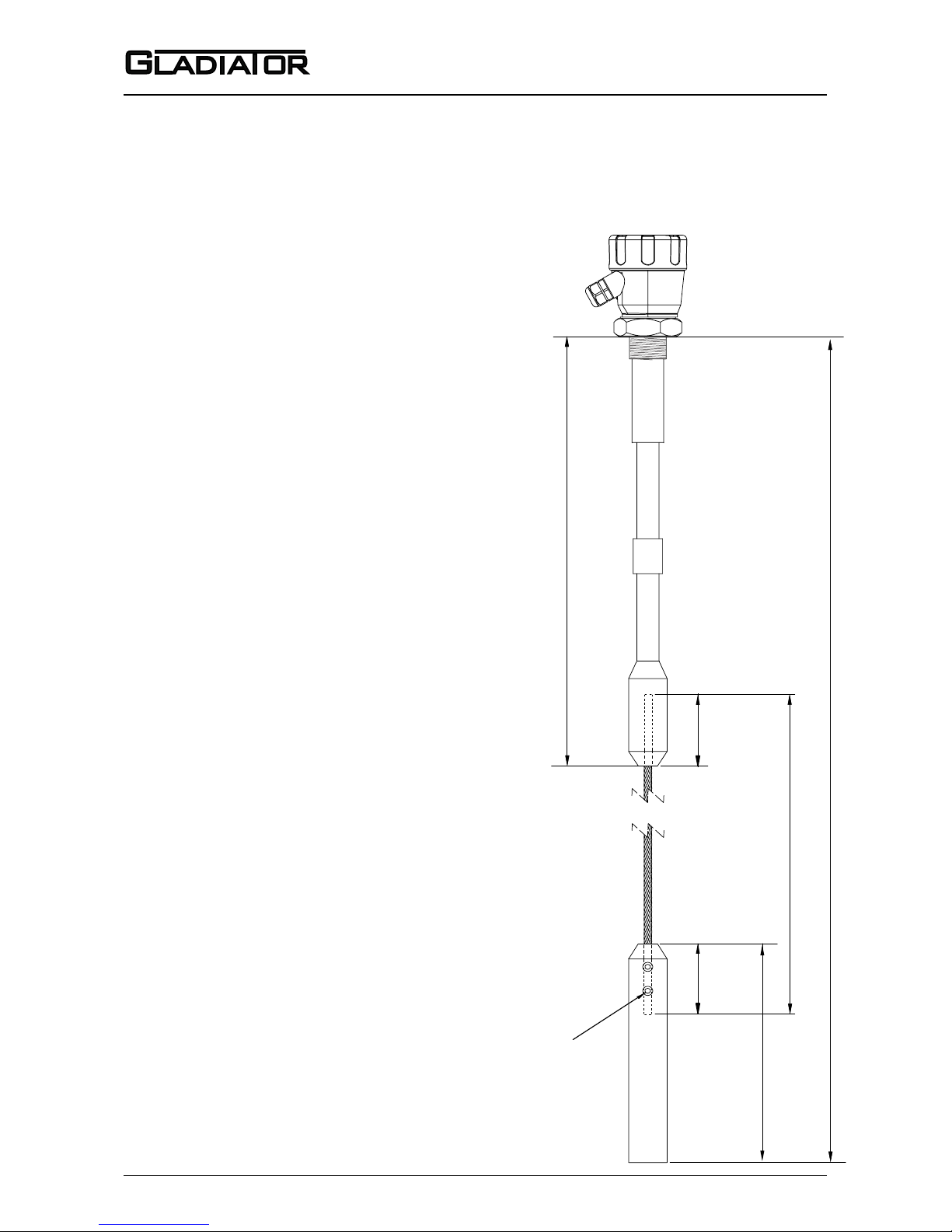
FLEXIBLE CABLE PROBE ADJUSTMENT
Notes for adjusting probe rope length
The Gladiator rope type probe can be
altered to any sensing length between
approx. 750mm and 3m by cutting down
from the standard sizes as required.
If a new rope is to be used, the rope
should be cut to:
Cable probe length - 549mm = new wire rope
length
(total sensing length - 549mm)
For example, within a 1000mm (1m) cable:
1000 = [rope + 549]
So rope length = 451mm
Remove or install the probe weight grub
screws with a 4mm allen key.
When fastening the rope, apply threadlocking adhesive onto grub screws
before re-installation.
Weight
Removable SS grub screws
for cable adjustment
Rope
Concealed
rope
Concealed
rope
250mm (9.8”)
83mm83mm
465mm (18.3”)
Cable Probe Length
Page 13
12
Admittance Smart Switch Series
Manual
Rev 1.2, June 2008
13
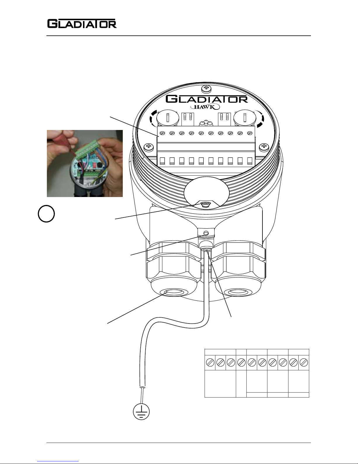
WIRING
SMART PROBE
RELAY
1. NC
2. COM
3. NO
COMMS DC-IN AC-IN
4. Test
12-30VDC
80-265 VAC
7.
8.
N
9.
L1
10.
1 2 3 4 5 6 7 8 9 10
RS 485
5.
B
6.
A
S
E
N
S
I
T
I
V
I
T
Y
D
E
L
A
Y
HI
FSH
TESTCAL
-
GLADIATOR SMART PROBE TERMINAL LAYOUT
Hole for securing of
optional identification tag
M4 grounding screw
Ground the housing to
vessel, if vessel is metallic.
Ground the housing to
plant ground, if vessel is
non-metallic.
The AC earth/ground
cable must be connected
to the ground screw
inside the housing when
using AC power.
If only one cable is used for both
power and output signal, then the
second entry port must be
plugged or blinded. Every Smart
unit is supplied with two M20
glands (or 3/4”NPT adaptors)
mounted on the unit and one
blind plug loose.
Remove Plug-In
terminal block for
easier wiring.
!
Page 14
13
Sultan 234 Series
Admittance Smart Switch Series
Manual
Rev 1.2, June 2008
1 2 3 4 5 6 7 8 9 10
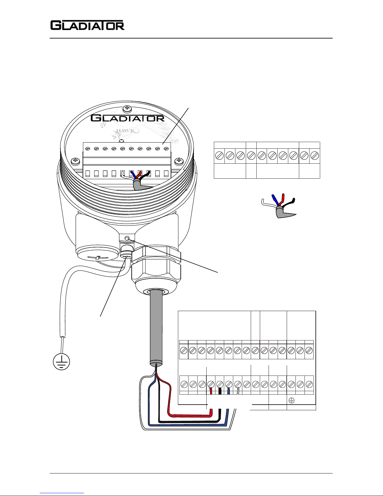
GLADIATOR REMOTE AMPLIFIER TERMINAL LAYOUT
GLADIATOR REMOTE PROBE TERMINAL LAYOUT
M4 grounding screw
7.1. 2. 3. 4. 5. 6.
8.
9.
10.
TRANSDUCER
RED
WHITE
BLUE
BLACK
Cable type between Amplifier and Probe
4 conductor shielded twisted pair instrument cable.
Conductor size dependent on cable length.
BELDEN 3084A, DEKORON or equivalent.
Max: BELDEN 3084A = 500m (1640 ft)
Max: DEKORON IED183AA002 = 350m (1150 ft)
Hole for securing of
optional identification tag
Ground the housing to
vessel, if vessel is metallic.
Ground the housing to
plant ground, if vessel is
non-metallic.
Remove Plug-In
terminal block for
easier wiring.
Terminals 1, 2, 3, 4, 9, 10 not used.
AC-IN
A
L1
+
–
DC-INCOMMSSENSOR
N
B
RELAY 2
(FAIL SAFE)
NC
COM
NO
RED
BLACK
BLUE
WHITE
24 VDC 80-265 VAC
RELAY 1
NC
COM
NO
Test in
NOT USED
CURRENT
+
–
Is
NOT USED
WIRING
REMOTE PROBE TO AMPLIFER
Page 15
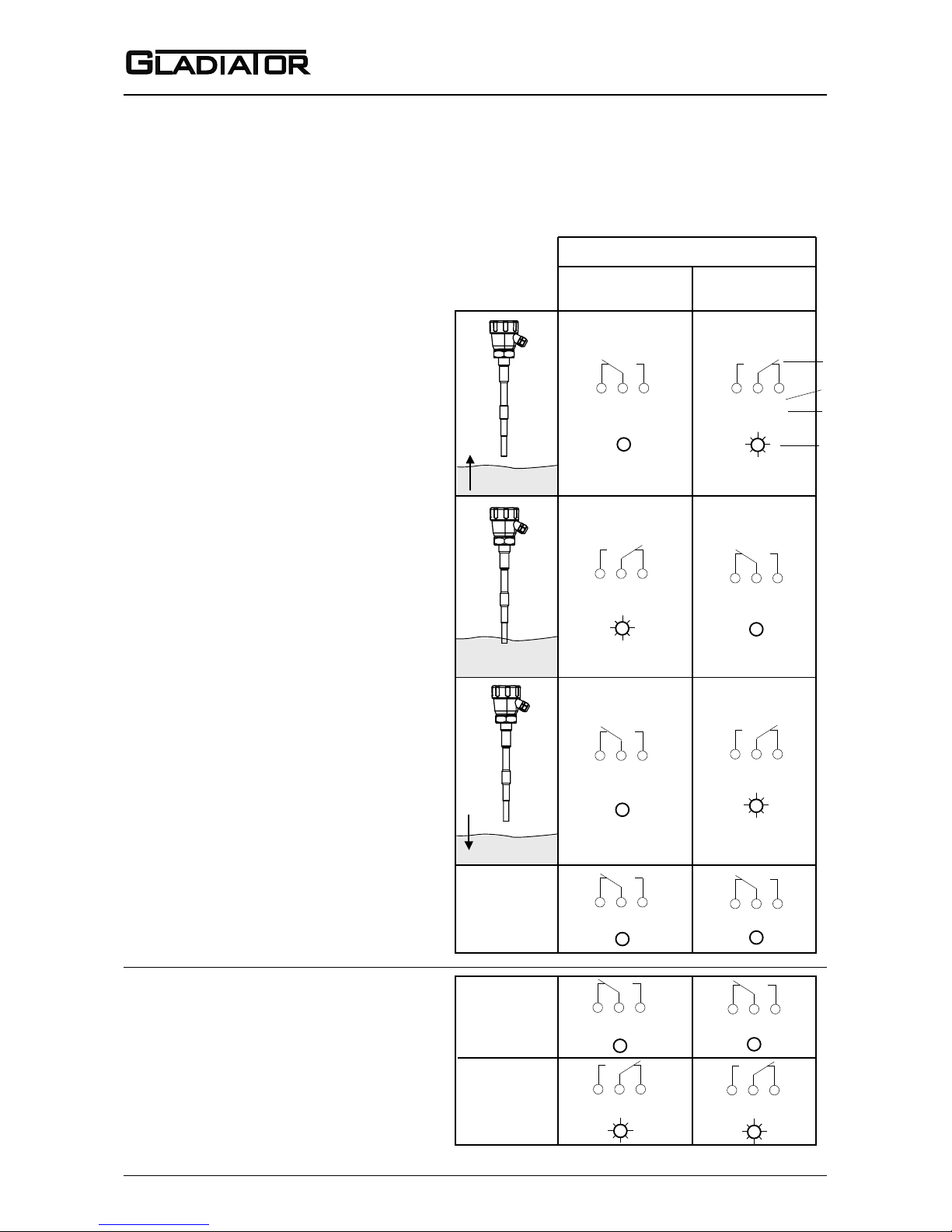
14
Admittance Smart Switch Series
Manual
Rev 1.2, June 2008
15
1 2 3
1 2 3
1 2 3
1 2 3
1 2 3
1 2 3
1 2 3
1 2 3
RISING LEVEL
(not detected)
CONTACT LEVEL
(detected)
FALLING LEVEL
(not detected)
NC NO
NC NO
NC NO
NC NO
NC NO
NC NO
NC NO
NC NO
COM COM
COM COM
COM COM
COM COM
POWER FAILURE
NC NO NC NOCOM COM
INTERNAL FAILURE
POWER FAILURE
OR
SYSTEM OPERATING
NORMALLY
NC NOCOM
NC NOCOM
State 1State 2State 1
Smart Probe
terminal numbers
Remote Amplifier
terminal function
labels
FailSafe Low
FSL
FailSafe High
FSH (default)
Relay Status
LED Status
Relay Action
WIRING
RELAY FUNCTIONS
FailSafe Switch Contact Action
Relay 2 - Remote version only.
For Smart Probes the Test terminal can act as a solid state output
with a similar function.
(see page 18)
Level Switch Contact Action
Relay - for Smart Probe Version
(Set Relay Action selection switch
pages 19 and 20)
Relay 1 - for Remote Version
(Set ‘Relay Action’ parameter
pages 23 and 26)
*It is possible for the Gladiator to
switch state before actual product
contact with the probe. State 2 represents product being detected by
the probe, even if it occurs without
contact.
Page 16
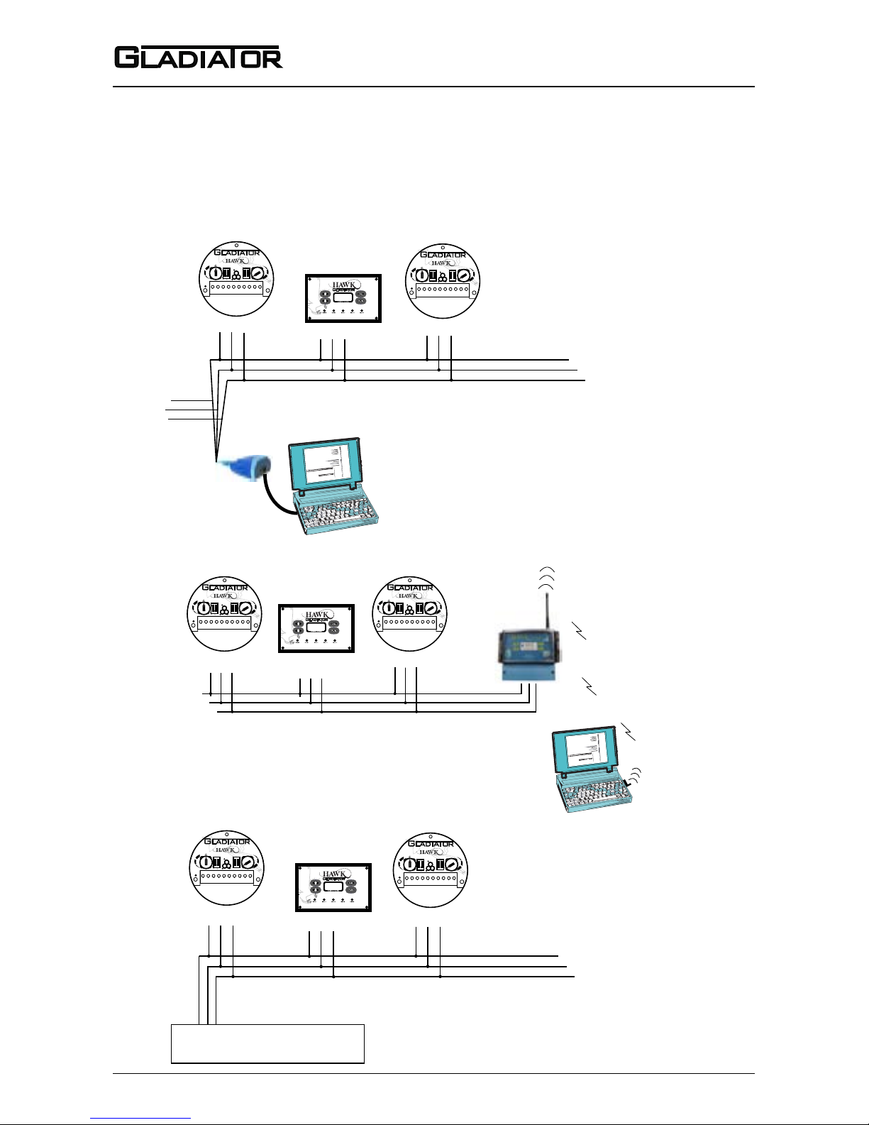
15
Sultan 234 Series
Admittance Smart Switch Series
Manual
Rev 1.2, June 2008
Laptop or PC Communications using
PCMCIA card or wired (PSTN) modem
and remote GSM/CDMA connection
with GosHawk software.
A B Gnd
A B Gnd
A B Gnd
Laptop or PC Communications using
Hawklink USB or RS485 / 232 converter
with GosHawk software.
Hawklink
USB
1 2 3 4 5 6 7 8 9 10
HI
LO
FSH
FSL
OFF OFF
TEST
CAL
ON ON
1 2 1 2
S
E
N
S
I
T
I
V
I
T
Y
D
E
L
A
Y
A B Gnd
A B Gnd
A B Gnd
PLC / DCS / SCADA for Remote
Communication with Modbus.
A B Gnd
A B Gnd
A B Gnd
1 2 3 4 5 6 7 8 9 10
HI
LO
FSH
FSL
OFF OFF
TEST
CAL
ON ON
1 2 1 2
S
E
N
S
I
T
I
V
I
T
Y
D
E
L
A
Y
HawkLink
GSM/CDMA unit
White
Blue
Black
Multidrop Connection Using HawkLink USB*
Multidrop GSM/CDMA Connection*
Multidrop Connection to PLC/DCS/SCADA*
* Wiring installation should follow
RS-485 standards for layout and
termination.
1 2 3 4 5 6 7 8 9 10
HI
LO
FSH
FSL
OFF OFF
TEST
CAL
ON ON
1 2 1 2
S
E
N
S
I
T
I
V
I
T
Y
D
E
L
A
Y
1 2 3 4 5 6 7 8 9 10
HI
LO
FSH
FSL
OFF OFF
TEST
CAL
ON ON
1 2 1 2
S
E
N
S
I
T
I
V
I
T
Y
D
E
L
A
Y
1 2 3 4 5 6 7 8 9 10
HI
LO
FSH
FSL
OFF OFF
TEST
CAL
ON ON
1 2 1 2
S
E
N
S
I
T
I
V
I
T
Y
D
E
L
A
Y
1 2 3 4 5 6 7 8 9 10
HI
LO
FSH
FSL
OFF OFF
TEST
CAL
ON ON
1 2 1 2
S
E
N
S
I
T
I
V
I
T
Y
D
E
L
A
Y
WIRING
MULTIDROP CONNECTIONS
Page 17
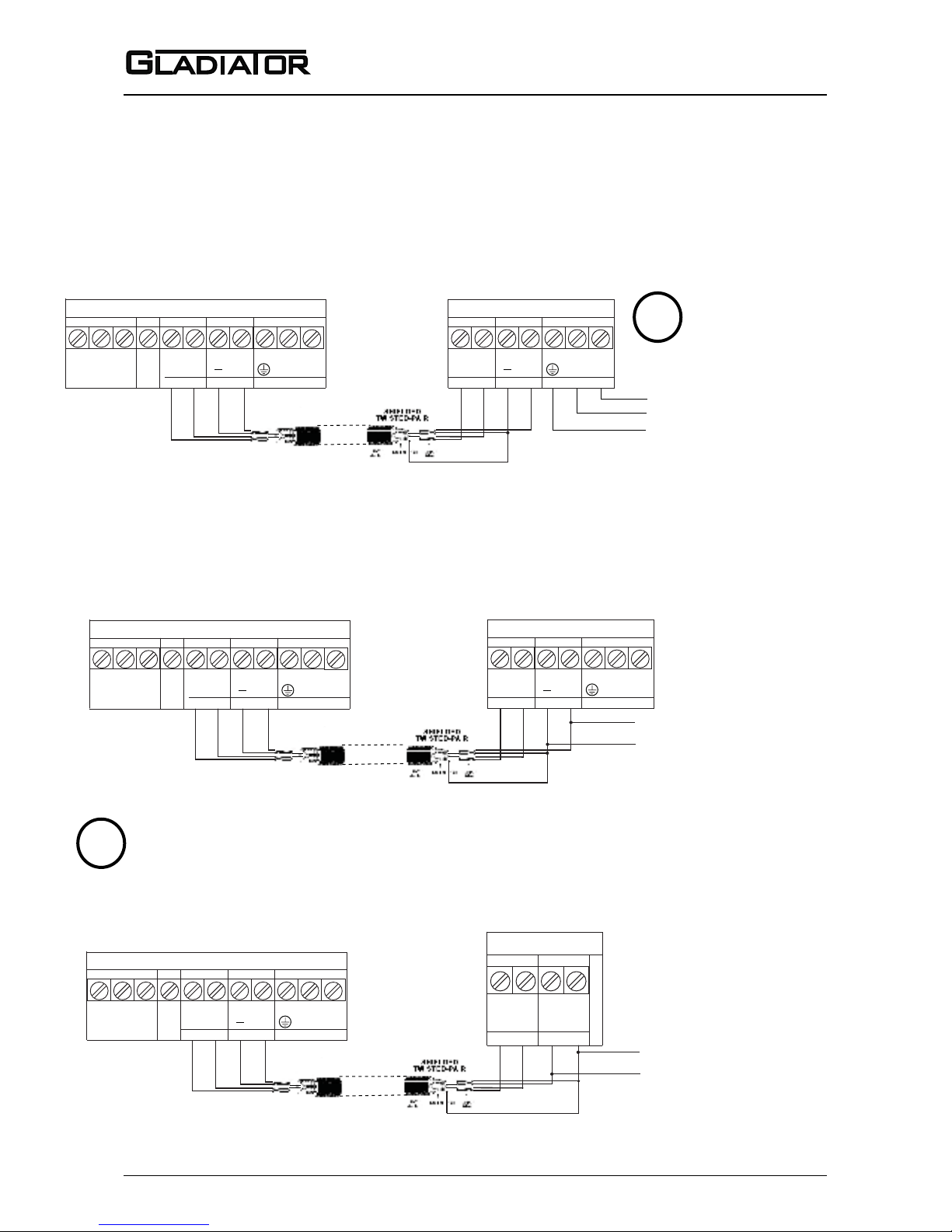
16
Admittance Smart Switch Series
Manual
Rev 1.2, June 2008
17
Connect shield to
DC “-” only at this end.
1 2 3 4
1 2 3 4
1 2 3 4
-
Existing DC power supply
Existing AC power
supply (GSM will be
powered by DC
generated by the Gladiator)
COMMS DC-IN
A
B
12-30VDC
GSM
RS 485
AC-IN
N
L1
80-265VAC
COMMS DC-IN
A
B
12-30VDC
GSM
RS 485
AC-IN
N
L1
80-265VAC
COMMS DC-IN
A
B
12-30VDC
REMOTE AMP
RS 485
AC-IN
N
L1
80-265VAC
COMMS DC-IN
A
B
12-30VDC
RS 485
-
Connect shield to
DC “-” only at this end.
1 2 3 4
2 1 4 3
SMART PROBE
COMMS DC-IN
A
B
12-30VDC
GSM
RS 485
AC-IN
N
L1
80-265VAC
Connect shield to
DC “-” only at this end.
1 2 3 4
COMMS DC-IN
A
B
12-30VDC
REMOTE AMP
RS 485
AC-IN
N
L1
80-265VAC
-
Existing DC power supply
USING DC POWER FROM GLADIATOR SMART PROBE
USING DC POWER DERIVED FROM AC POWERED REMOTE GLADIATOR
USING DC POWER FROM REMOTE GLADIATOR
WIRING
HAWKLINK GSM - CONNECTING POWER AND COMMS
!
NOT POSSIBLE WITH
GLADIATOR SMART
PROBES. INTERNAL
POWER SUPPLY HAS INSUFFICIENT CAPACITY.
!
TERMINAL ORDER VARIES BETWEEN GLADIATOR SMART PROBE
AND REMOTE AMPLIFIER. ENSURE CORRECT LAYOUT IS USED.
Page 18
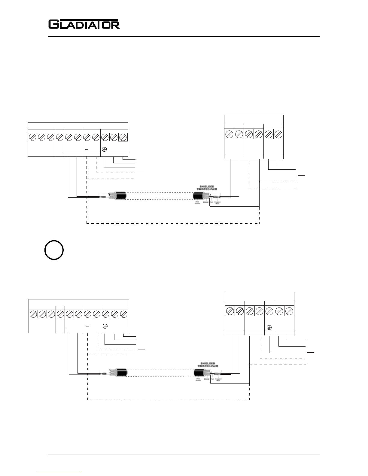
17
Sultan 234 Series
Admittance Smart Switch Series
Manual
Rev 1.2, June 2008
COMMS DC-IN
A
B
12-30VDC
GSM
RS 485
Connect shield to
DC “-” only at this end.
1 2
2 1
AC-IN
N
L1
Separate AC power supply
for the GSM module
or
DC power
supply
COMMS DC-IN
A
B
12-30VDC
RS 485
-
AC-IN
N
L1
80-265VAC
Existing AC
or
DC power
supply
SMART PROBE
80-265VAC
COMMS DC-IN
A
B
12-30VDC
GSM
RS 485
Connect shield to
DC “-” only at this end.
1 2
1 2
AC-IN
N
L1
Separate AC power supply
for the GSM module
or
DC power
supply
COMMS DC-IN
B
A
12-30VDC
RS 485
-
AC-IN
N
L1
80-265VAC
Existing AC
or
DC power
supply
REMOTE AMP
80-265VAC
*
*
*Ensure separate DC supplies have the same ground potential
!
TERMINAL ORDER VARIES BETWEEN GLADIATOR SMART PROBE
AND REMOTE AMPLIFIER. ENSURE CORRECT LAYOUT IS USED.
WIRING
HAWKLINK GSM - CONNECTING POWER AND COMMS
USING SEPARATE AC OR DC POWER WITH SMART PROBE
USING SEPARATE AC OR DC POWER WITH REMOTE GLADIATOR
Page 19
18
Admittance Smart Switch Series
Manual
Rev 1.2, June 2008
19
Terminal Block
PLC / SCADA / DCS Output
Test
Terminal Block
Test
Test
Coil rating
500mW max
or 50mA max
Test
To switch an external relay
+12-24Vdc
PLC
SCADA
DCS Input
Pull up
12-24Vdc
max 50mA
To a PLC input
Externally provided
test button
!
!
PLC/SCADA/DCS GROUND MUST
CONNECT BACK TO GLADIATOR
GROUND OR DC ‘-’ TERMINALS
EXTERNAL PUSH BUTTON GROUND
MUST CONNECT BACK TO GLADIATOR
GROUND OR DC ‘-’ TERMINALS
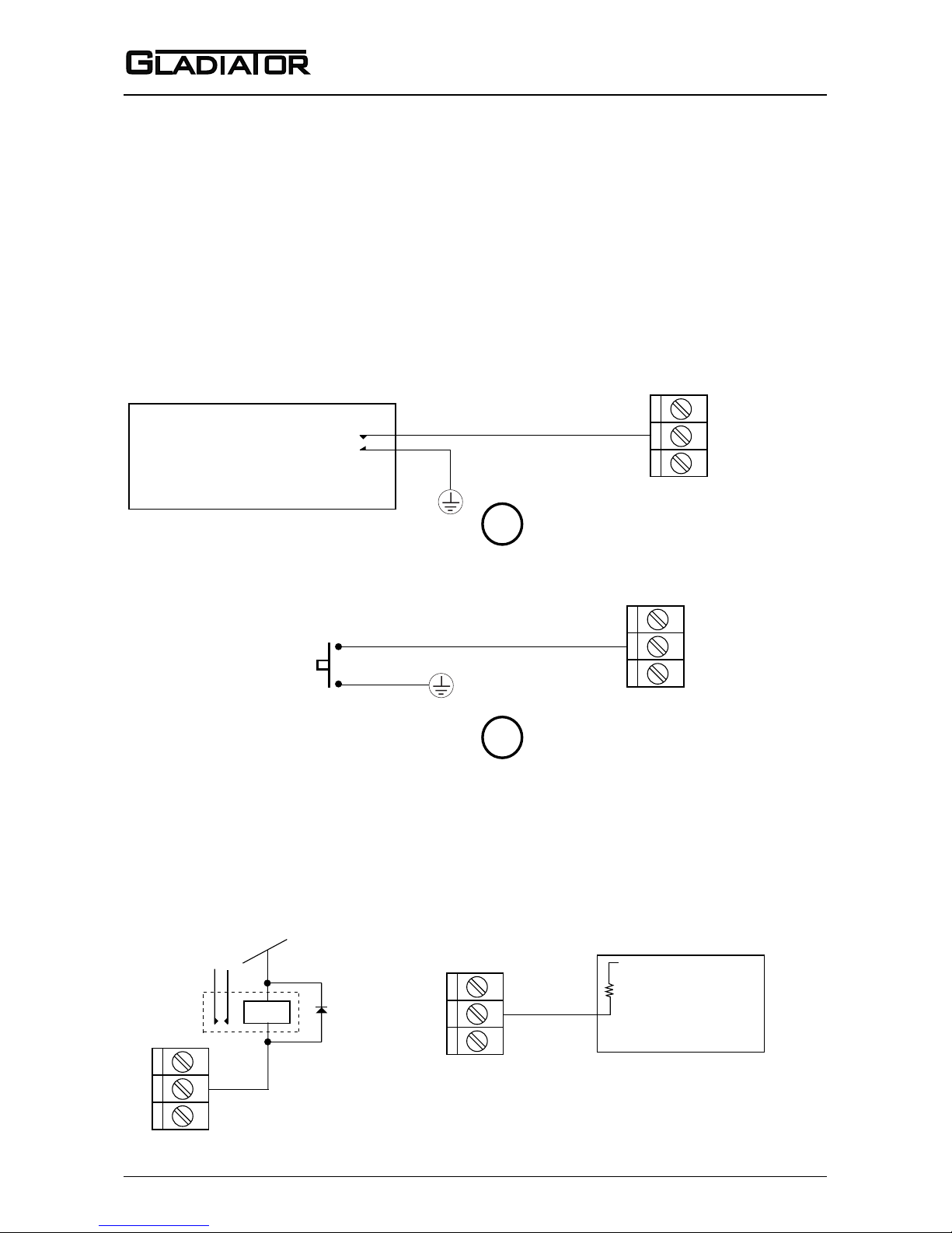
Test terminal will provide an output which is able to switch an external failsafe relay or PLC/SCADA/DCS input.
During normal system operation this terminal will internally switch a solid state output to ground (or DC ‘-’).
If power fails or an internal system failure occurs, the terminal will act as an open circuit.
Relay will turn on during
normal system operation
or off in failed or unpowered
conditions.
Input will detect ‘0’ state during normal system
operation, or ‘1’ in failed or unpowered conditions.
WIRING
TEST TERMINAL FUNCTION SELECTION
TEST INPUT MODE
Test switch must be in ‘TEST’ (ON) position on Smart Probe - function always enabled on Remote Ampli-
er.
Test terminal acts as an input for remote testing of the instrument’s switching function.
Used to check for malfunction of unit from a remote position, PLC, SCADA etc. For more
information see page 21.
TEST INPUT FROM PLC/SCADA/DCS DIGITAL OUTPUT
OPERATOR CONTROLLED PRESS TO TEST
FAILSAFE OUTPUT MODE (Test switch must be in the ‘OFF’ position - default setting)
Page 20
19
Sultan 234 Series
Admittance Smart Switch Series
Manual
Rev 1.2, June 2008
1 2 3 4 5 6 7 8 9 10
HI
LO
FSH
FSL
OFF OFF
TEST
CAL
ON ON
1 2 1 2
S
E
N
S
I
T
I
V
I
T
Y
D
E
L
A
Y
1
5
2
7
10
11
8
3
6
4
9
1
2
3
4
5
6
7
8
9
10
11
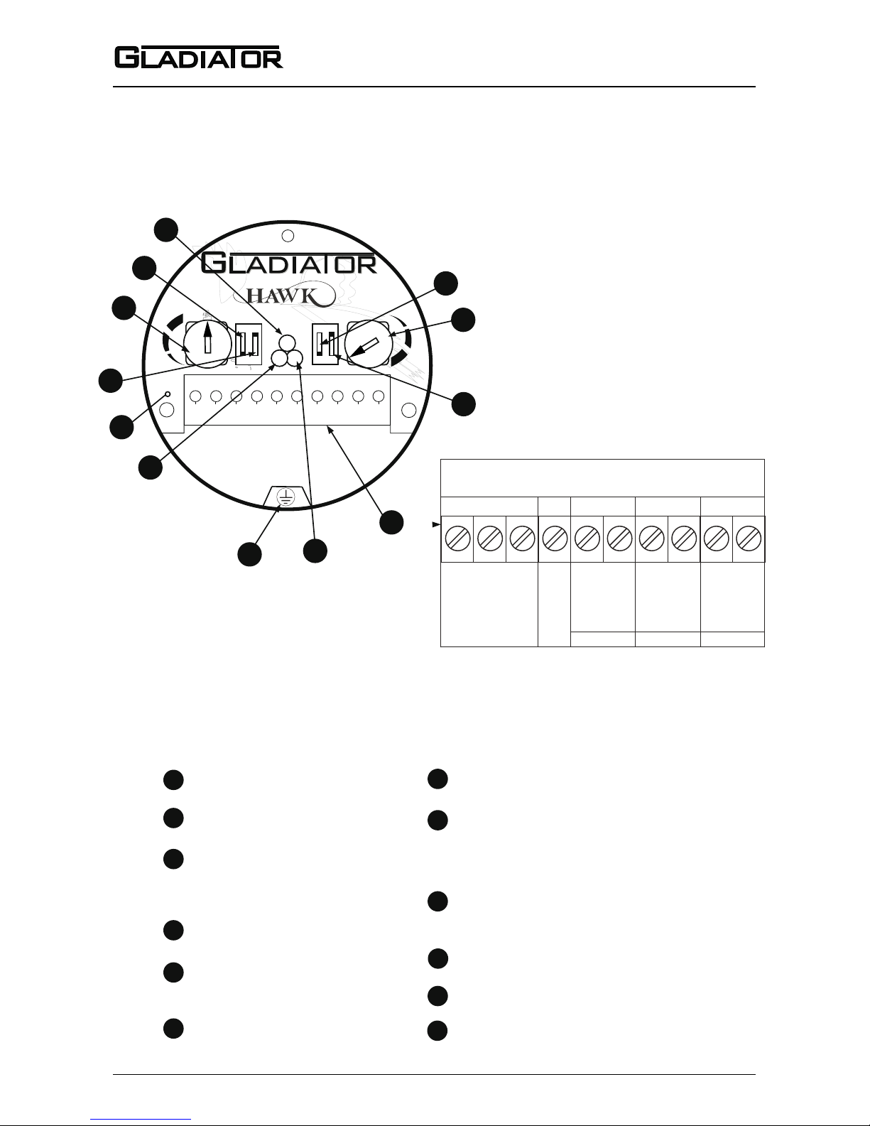
Mounting Calibration switch CAL/OFF
Relay action selection
switch
FSH - FailSafe High
FSL - FailSafe Low
Sensitivity Potentiometer
Default 50% = 12 o’clock
HI / LO sensitivity switch
BLUE LED:
Blinking indicates calibration function is on.
Continuously ON indicates failed calibration.
AC Ground - must be used for
AC powered installations
GREEN LED: Power / Status
Blinks to indicate the functioning
is correct and no media is detected.
Continuously ON when media is detected.
Removable terminal block - plug in type
Delay Potentiometer (0-20 sec)
(Default 0 sec. at minimum
position)
Test input function select TEST/OFF
RED LED: Relay status
ON when relay coil is energised
RELAY
1. NC
2. COM
3. NO
COMMS DC-IN AC-IN
4. Test
12-30VDC
80-265 VAC
SMART PROBE REMOVABLE
TERMINAL BLOCK
7.
8.
N
9.
L1
10.
RS 485
5.
B
6.
A
Functionality Description (bold is default)
+ -
12
signal
12
Signal indicator
SETUP PROCEDURE
SMART PROBE FUNCTIONALITY LAYOUT
(see page 14)
- Not used in Gladiator Admittance products
Page 21

20
Admittance Smart Switch Series
Manual
Rev 1.2, June 2008
21
SETUP PROCEDURE
SMART PROBE VERSION
1. Mount the unit in its actual position.
(See mounting procedure - pages 9-10)
Make sure that external ground wire is connected between the outside ground screw on
the Gladiator housing and the roof/wall/side
of the silo/tank/vessel/chute. (For non metallic tanks make sure that external ground
wire is connected between the same outside
ground screw on the housing and the general plant ground potential).
2. Check where the actual level is relative
to the probe.
Make sure that product is not touching the
probe - ideally it needs to be > 500mm away.
(If the silo/vessel/tank/chute is very small
you must ensure that the material is as far
away as possible - it must not be touching
the probe).
3. Turn the power on.
The green LED will either stay on for 2 seconds then begin ashing or stay on permanently to indicate operation.
4. Select the required relay contact action.
The Relay can switch ‘ON’ or ‘OFF’ as the
product approaches the probe and switch
‘ON’ or ‘OFF’ in response to an instrument
failure (for details see page 14). Set the relay
action selection switch position (FSL or FSH)
depending on your requirements.
5. Cancel inuence of mounting and/or
build up.
Do not proceed with this step unless the
product is not touching the probe. Ideally the
level needs to be > 500mm away.
Switch the Mounting Calibration switch to
‘CAL’ (ON) position. The Blue LED will blink
to indicate that mounting calibration is
now in progress.
Wait for at least 10 sec. then switch the
mounting calibration switch to ‘OFF’ position.
The blue LED should turn off after a short
time. The Blue LED will stay on if there
was a calibration error. If this is the case
please check that the probe is not touching
the product or the mounting, then try the
calibration again. If mounting calibration was
successful the blue LED should be off and
the Green LED should blink every 2 sec.
Unit is now able to cancel inuence of
mounting and/or build-up and probe history
has been cleared.
6. Select the sensitivity.
There are two adjustments controlling the
sensitivity of the switch point:
6.1. The ‘HI/LO’ sensitivity switch is used
to set your unit depending on the dielectric
properties of the product to be measured.
This switch sets the range of adjustment
possible with the sensitivity potentiometer.
If the material to be detected has a lower
dielectric constant than 10 - set the switch to
‘HI’ (ON) - default.
If material to be detected has a higher dielectric constant than 10 - set switch to ‘LO’
If you are not aware of your material dielectric constant – set the switch to ‘HI’ (ON)
- default.
6.2 The sensitivity potentiometer.
Set the potentiometer according to your
requirements. A 12 o’clock setting (50%)
- default, will cover the majority of instances
- for the remaining instances, turning the
potentiometer anti clockwise will decrease
sensitivity. Switch point will then occur with
the material nearer to the probe or more
in contact with the probe than before. The
reverse is also true.
Page 22

21
Sultan 234 Series
Admittance Smart Switch Series
Manual
Rev 1.2, June 2008
SETUP PROCEDURE
SMART PROBE VERSION
The test function allows you to check the
functionality of the unit. Applying a ground
wire to the Test terminal will change the
state of the relay. It will hold this state until
the ground is removed, then it will change
back to the standard running mode.
If the unit was in a Fail mode then the relay
will not change status.
‘OFF’ (Default) Position: Fail safe output
function is selected. Test terminal (terminal
number 4 of Smart probe) will function as an
open drain drive. This can be used to drive a
relay or an active low PLC input to detect a
Fail condition. In normal operation mode the
Test terminal will output Zero Volts (Short to
GND). In Fail or unpowered mode the Test
terminal will be open circuit.
See page 18 for further information.
7. Select the time delay
Set the required delay using the Delay
potentiometer. (Default is 0 sec. at minimum
position) Turn the potentiometer clockwise if
any delay is required. Maximum rotation is
¾ of a revolution. Max delay is 20 sec. The
selected delay will be used for both an ON
delay and
an OFF delay.*
8. Test function (used to check for
malfunction of unit from remote position,
PLC, SCADA etc)
Select the desired Test function by switching
the ‘Test’ switch (Default = ‘OFF’).
‘TEST’ (ON) Position: Test function is
selected. Test terminal (terminal number 4 of
Smart probe) is used as an input to the unit.
* Setting of different time ranges for the delay potentiometer for ON delay and OFF delay is possible using a PC connected via GosHawk2 software. By default, both will have the same time adjustment range
(20 sec max) and adjustment will result in equal ON delay and OFF delay.
Page 23
22
Admittance Smart Switch Series
Manual
Rev 1.2, June 2008
23
SETUP PROCEDURE
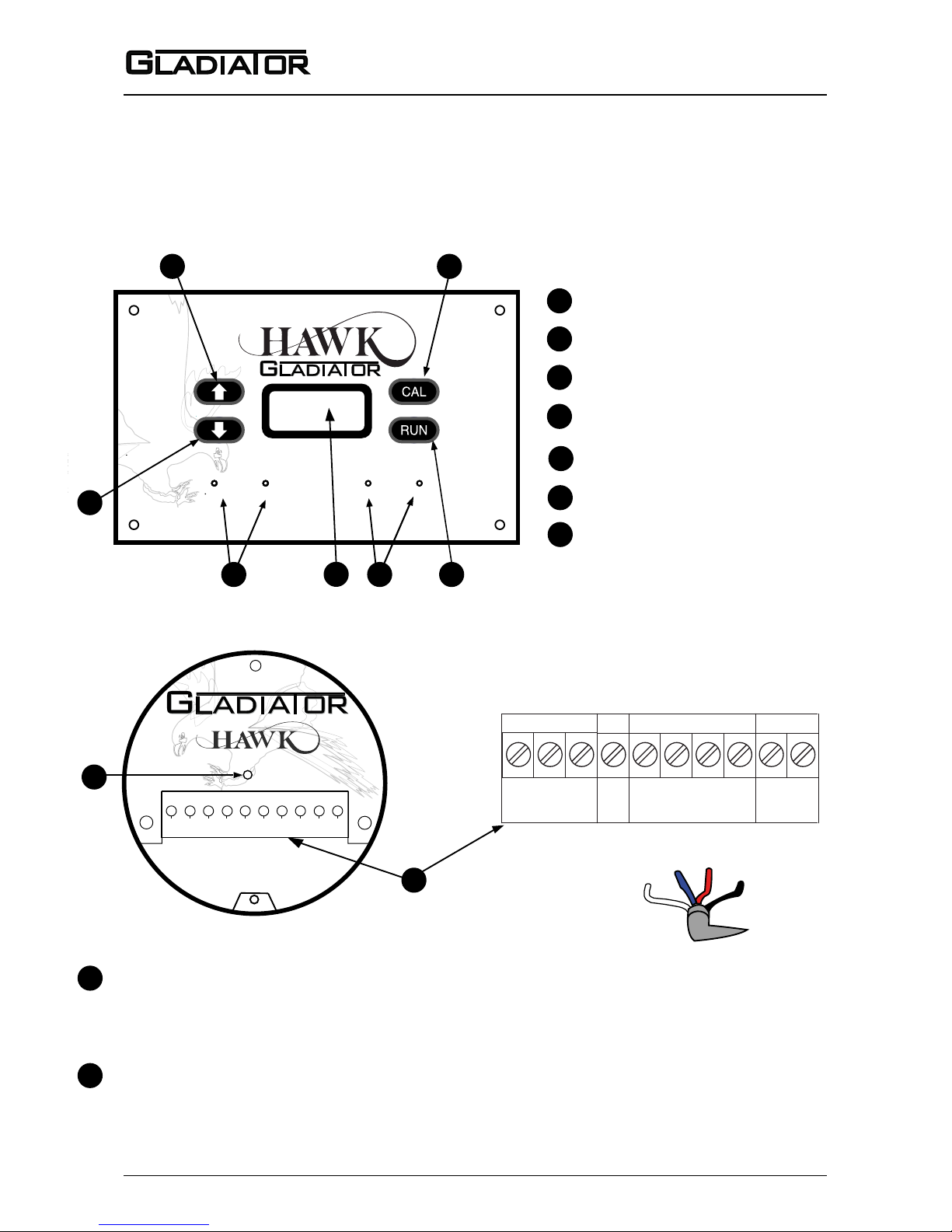
REMOTE FUNCTIONALITY LAYOUT
STATUS
REMOTE
1 2 3 4 5 6 7 8 9 10
8
9
1
2
3
4
5
8
9
Calibrate button
Down button
Up button
Relay LEDs 1 and 2
Run button
Removable terminal block - plug in type
1
2
3
4
5
GREEN LED: Power / Status
Blinks every 1/2 second to indicate that functioning
is correct and no medium is detected.
LED on continuously indicates correct functioning and media is detected.
REMOVABLE REMOTE PROBE TERMINAL BLOCK
7.1. 2. 3. 4. 5. 6.
8.
9.
10.
TRANSDUCER
RED
WHITE
BLUE
BLACK
6
6
Display (LCD with backlight)
Terminals 1, 2, 3, 4, 9, 10 not used.
7
Status LEDs A and B
- Status A flashes with probe to amplifier communications
- Status B has no function in this product
7
STATUS A STATUS BRELAY 2RELAY 1
Page 24
23
Sultan 234 Series
Admittance Smart Switch Series
Manual
Rev 1.2, June 2008
SETUP PROCEDURE
REMOTE VERSION
1. Mount the unit in its actual position. (see mounting procedure - page 9-10)
Make sure that external ground wire is connected between the outside ground screw on the Gladiator housing and the roof/wall/side of the silo/tank/vessel/chute. (For non metallic tanks make sure
that external ground wire is connected between the same outside ground screw on the housing
and the general plant ground potential.)
2. Check where the actual level is relative to the probe.
Make sure that product is not touching the probe - ideally it needs to be > 500mm away.
(If the silo/vessel/tank/chute is very small you must ensure that the material is as far away as possible - it must not be touching the probe).
3. Turn the power on
The display will turn on and the failsafe relay will switch. The display will scroll through the following messages: Hawk, Amp SerialNo, Type, Amp Soft Ver, Device ID, SensorSerial, SensorModel,
Sens SoftVer, Sensor Addrs, Gladiator System Amp.
The unit will then go into operational mode displaying ‘Switch’ with a % value. This % value represents the changing admittance reading.
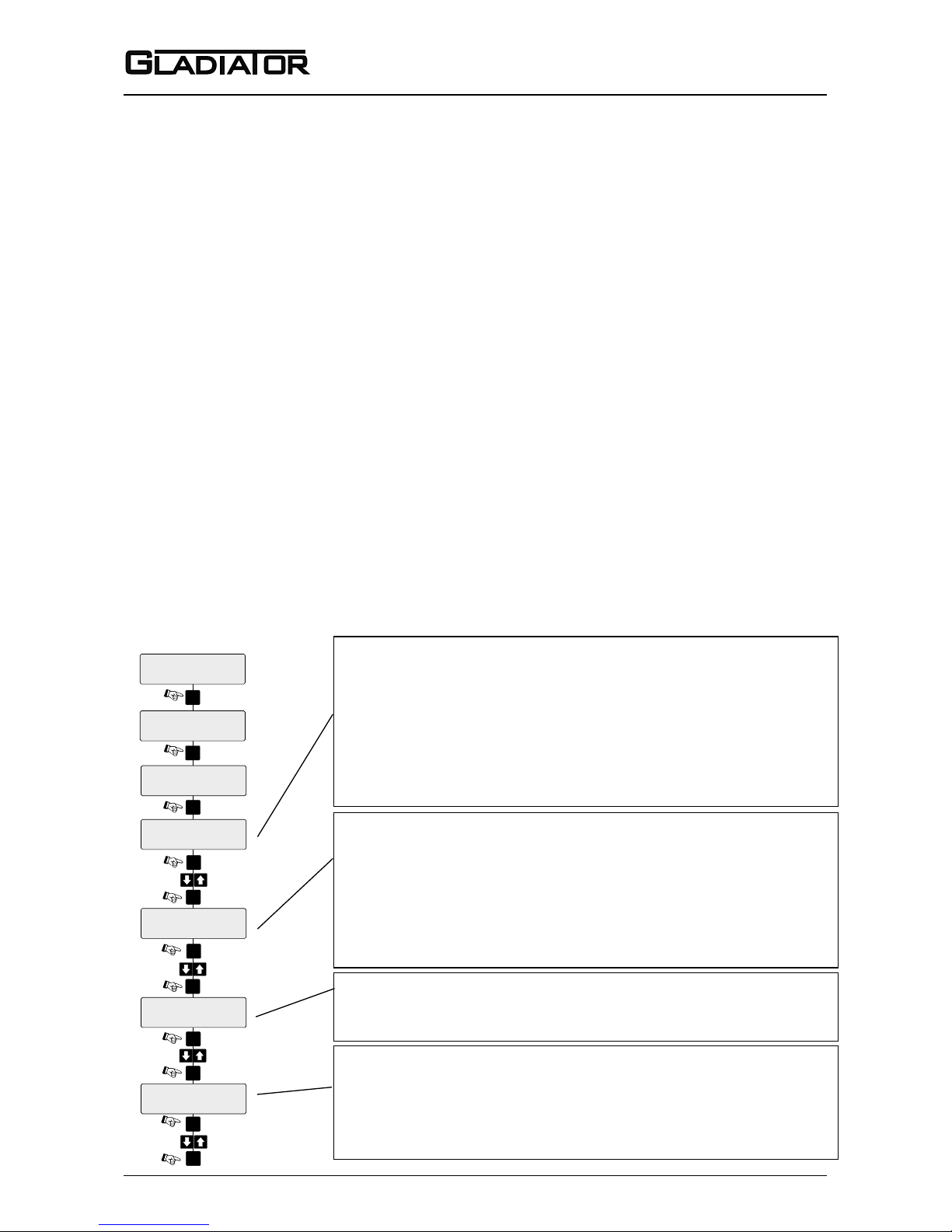
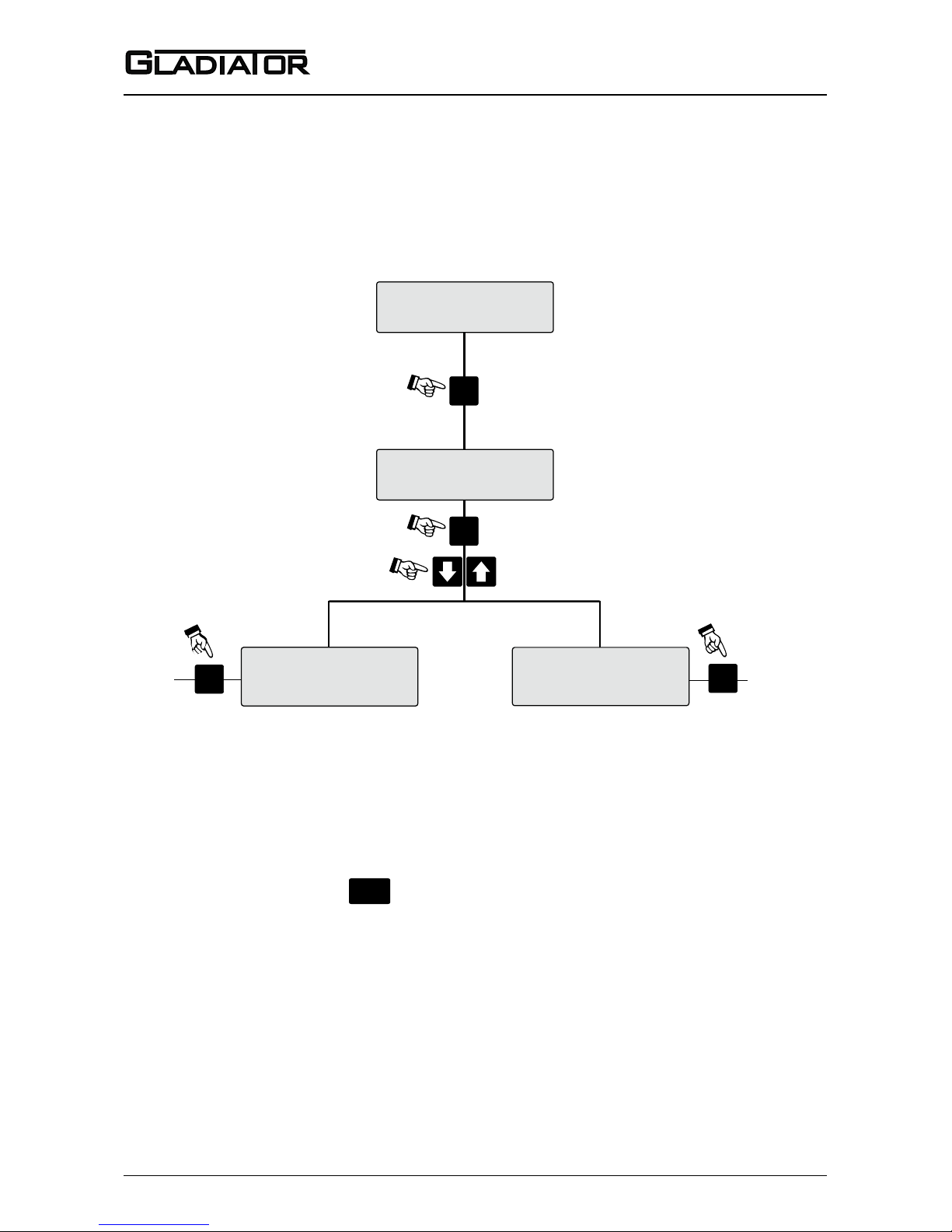
4. Simple “1-minute” Setup - Follow the ow chart
QuickSet
Cal Mounting
Yes / No
Relay Action
FailSafe Hi
UnLock
0
Sensor Value
0.0%
CAL
CAL
Press
Press
CAL
CAL
CAL
Press
Press
Press
Press
CAL
CAL
Press
CAL
CAL
CAL
RUN
Press
Press
Press
Press
Twice
Switch Point
50%
Delay Adjust
0.1S
Yes
50%
0.1S
FailSafe Hi
FailSafe Low
Select the Switch point (sensitivity)
The output relay will switch at the entered % value. The default value of
50% will be suitable for detecting most media. For detection of products
having low dieletric constant, select a lower % value and vice versa. A
higher % value will require the product to come nearer to the probe or
cover more of the probe before switching will occur. When the level falls
the relay will switch back at half of the entered switch point % value.
Select the Time Delay
Set the time to be used for both switch on and switch off delays
(default: 0.1 seconds). Maximum Delay is 40 seconds.
Cancel Inuence of Mounting and/or Buildup
Do not proceed with this step unless the product is not touching the
probe. Ideally it needs to be > 500mm away.
Select ‘Yes’ to start the mounting calibration. ‘Wait’ will be displayed during the calibration for up to 30 seconds.
Unit is now able to cancel the inuence of the mounting and/or
build-up. The % reading has been zeroed with the existing process
conditions and probe history log has been cleared.
Select the required relay action
The Relay can switch ‘ON’ or ‘OFF’ as the product approaches the
probe and switch ‘ON’ or ‘OFF’ in response to an instrument failure.
For details see page 14. Set the parameter to FailSafe Low or
FailSafe Hi depending on your requirements.
Page 25
24
Admittance Smart Switch Series
Manual
Rev 1.2, June 2008
25
SOFTWARE MENU
REMOTE AMPLIFIER
In Run Mode
(A) Press and hold - interrupts normal operations and allows access
to software menu headings.
In Calibrate Mode
(B) Steps into a menu selection to allow editing (down one level)
(C) Saves selected value and moves onto the next menu item.
ENTERING DATA
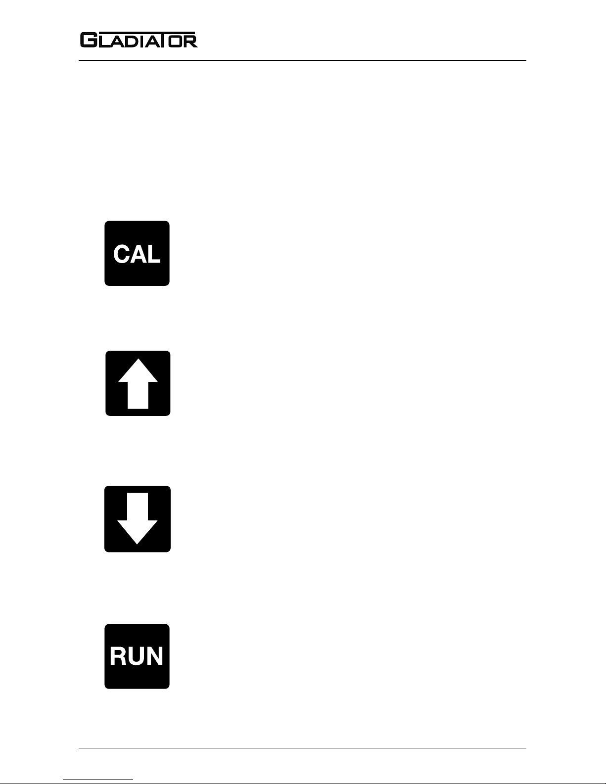
All software adjustments are achieved via the four PUSHBUTTONS on the front
panel.
In Run Mode
(A) Scrolls up through operating diagnostics on display LCD.
In Calibrate Mode
(B) Scrolls up through software parameters when browsing the
menus.
(C) Increases display value when editing a parameter.
In Run Mode
(A) Scrolls down through operating diagnostics on LCD display.
In Calibrate Mode
(B) Scrolls down through software parameters when browsing the
menus.
(C) Decreases display value when editing a parameter.
In Run Mode
(A) Hides diagnostics if they are in view and returns to the standard
running display.
In Calibrate Mode
(B) Steps out of a menu or selection (up one level). Parameter value
will be stored automatically when stepping up.
(C) Returns to running mode from the top level menu.
Page 26
25
Sultan 234 Series
Admittance Smart Switch Series
Manual
Rev 1.2, June 2008
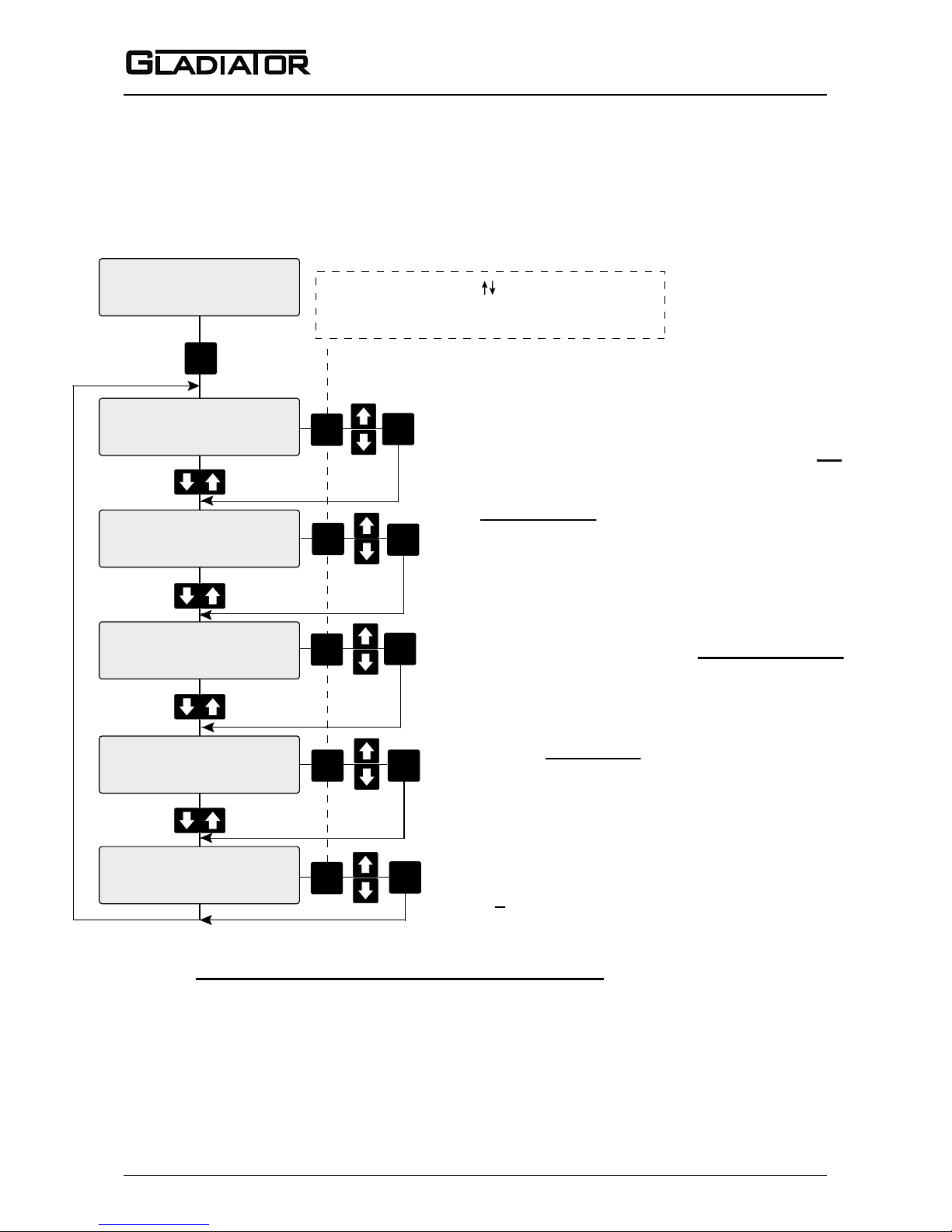
QuickSet
Advanced
To Calibrate
UnLock
0
Sensor Value
0.0%
Advanced Menu
covers less commonly
used or advanced
parameters.
CAL
CAL
Press
Press
QuickSet Menu
covers all parameters
required for standard
setups.
On first start up there is
no security code protection.
Press
CAL
Press
To QuickSet
flow chart
CAL
Press
To Advanced
flow chart
Normal Running Display
to return to normal operation
RUN
Press
FLOW CHART
SOFTWARE TREE
SOFTWARE VERSION 7.14
See page 26
See page 27
Page 27
26
Admittance Smart Switch Series
Manual
Rev 1.2, June 2008
27
FLOW CHART
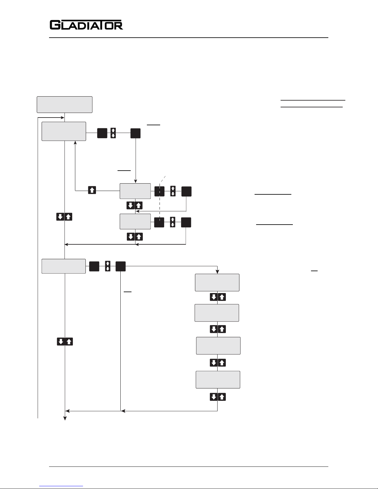
QUICKSET
Relay 1 will switch at the entered Switch Point
value (default 50%) and switch back at half of this
value. Manual will be displayed if you
have set the parameter ‘Switch Mode’ to Manual in
Advanced menu. The Manual setting can only be
removed or adjusted from the Advanced menu.
CAL
CAL
Relay Action
FailSafe Hi
Lock Code
0
Relay Action (FailSafe Hi or FailSafe Low)
CAL
Set switch delay time 0.1-40sec (default 0.1 sec).
Security code lock
Adjustable 0-200
Default 0
CAL
Calibrate mount will cancel the mounting influence
and zero the % reading with the existing process
conditions. Probe history log will be cleared.
Vessel must be empty before calibration. Yes / No
CAL
Default values/settings in bold and underlined
QuickSet
Switch Point
50%
Delay Adjust
0.1S
Cal Mounting
No
CAL
CAL
CAL
CAL
CAL
CAL
*When CAL is pressed ‘ edit’ will flash on the
bottom line of the display for a short time to indicate
that the parameter is being opened for editing.
(see page 14)
Page 28
27
Sultan 234 Series
Admittance Smart Switch Series
Manual
Rev 1.2, June 2008
FLOW CHART
ADVANCED MENU
CAL
Auto -
Switch point is set in QuickSet by the ‘Switch Point’ parameter.
‘
Switch On’ = ‘Switch
Point’
, ‘Switch Off’ = Half of ‘Switch
Point’
value
(by default).
‘Switch On’ and ‘Switch Off’ can not be changed (view only) in Auto.
Manual - ‘Switch On’ and ‘Switch Off’ values can be edited in Manual
mode. Manual editing over-rides the QuickSet selected
values.
CAL
Relay switch point On (Default 50%)
*Output relay in ‘State 2’ above this value.
CAL
Relay switch point Off (Default 25%)
*Output relay in ‘State 1’ below this value.
Manual
(editable) *Only possible if manual selected
Auto
(view only)
Advanced
Switch Mode
Auto
Switch On
50%
Switch Off
25%
Default values/settings
in bold and underlined
CAL
CAL
CAL
*Switch points are refered to as ‘On’ and ‘Off’ to
reflect the most simply understood performance in FailSafe Low
mode. Actual relay state may be different according
to setting of relay contact action.
Min Sensor %
0.0%
Minimum Sensor % since last
Reset Log (not adjustable).
Maximum Sensor % since last
Reset Log (not adjustable).
Minimum temperature value since
last Reset Log (not adjustable).
Maximum temperature value since
last Reset Log (not adjustable).
View Log
Max Sensor %
288.4%
Min Temp
20.0C
Max Temp
26.9C
CAL
CAL
No
Yes
View history log of probe
% and temperature Yes / No
Continued next
page (Reset Log)
(see page 14)
Page 29
28
Admittance Smart Switch Series
Manual
Rev 1.2, June 2008
29
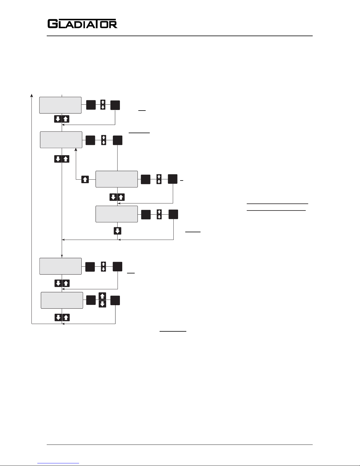
FLOW CHART
ADVANCED MENU
CAL
Reset probe history log
(Yes / No)
Log will automatically reset when Cal Mounting is used in
QuickSet to cancel mounting influences and re-zero the % reading.
Default values/settings
in bold and underlined
Reset Log
No
CAL
1200
4800
9600
19200
38400
57600
Modbus
HART
Profibus DP
DeviceNet
1-255
Comms Type
Modbus
CAL
Device ID
1
Baud Rate
19200
CAL
CAL
CAL
CAL
CAL
Selection should not be changed
unless required hardware is
present.
CAL
Display Span: 0-100% change in displayed value will occur with the
selected change of raw internal units.
Changing of this parameter will change the value of the Switch Point
(Switch On and Switch Off) values.
Back Light
On
Display Span
3
CAL
Display Backlight
On/Off
CAL
CAL
From previous page
0. 0 - 40000 2. 0 - 20000 4. 0 - 5000
1. 0 - 30000
3. 0 - 10000 5. 0 - 1000
(see part numbers - page 34-35)
Page 30
29
Sultan 234 Series
Admittance Smart Switch Series
Manual
Rev 1.2, June 2008
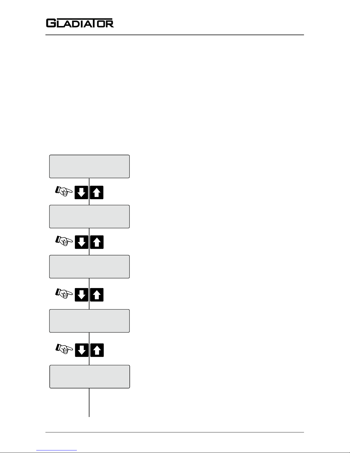
Normal
0.0%
Press
Press
Press
Min: 0.0%
0.0%
Press
Operation Mode
Current temperature inside probe housing (ºCelsius).
Programmed switch On / switch Off delay (seconds).
Minimum captured Sensor Value % since last history
log reset, or last Cal Mounting operation.
Normal / Comms Retry / Fail
Sensor Value
0.0%
Temp: 23.3C
0.0%
Delay: 0.1S
0.0%
(Continued next page)
FLOW CHART
DIAGNOSTIC DISPLAYS (Remote type only)
The diagnostic displays appear on the top line of the LCD, after pressing the Up or
Down push button when the Gladiator switch is in its normal running mode.
The diagnostics provide the user with valuable performance feedback on how the
instrument is performing whilst in operation.
The measured reading Sensor Value (%) continues to be displayed on the second
line of the LCD during diagnostic viewing on the top line. Ouput relays will continue to
operate during diagnostic viewing.
Page 31
30
Admittance Smart Switch Series
Manual
Rev 1.2, June 2008
31
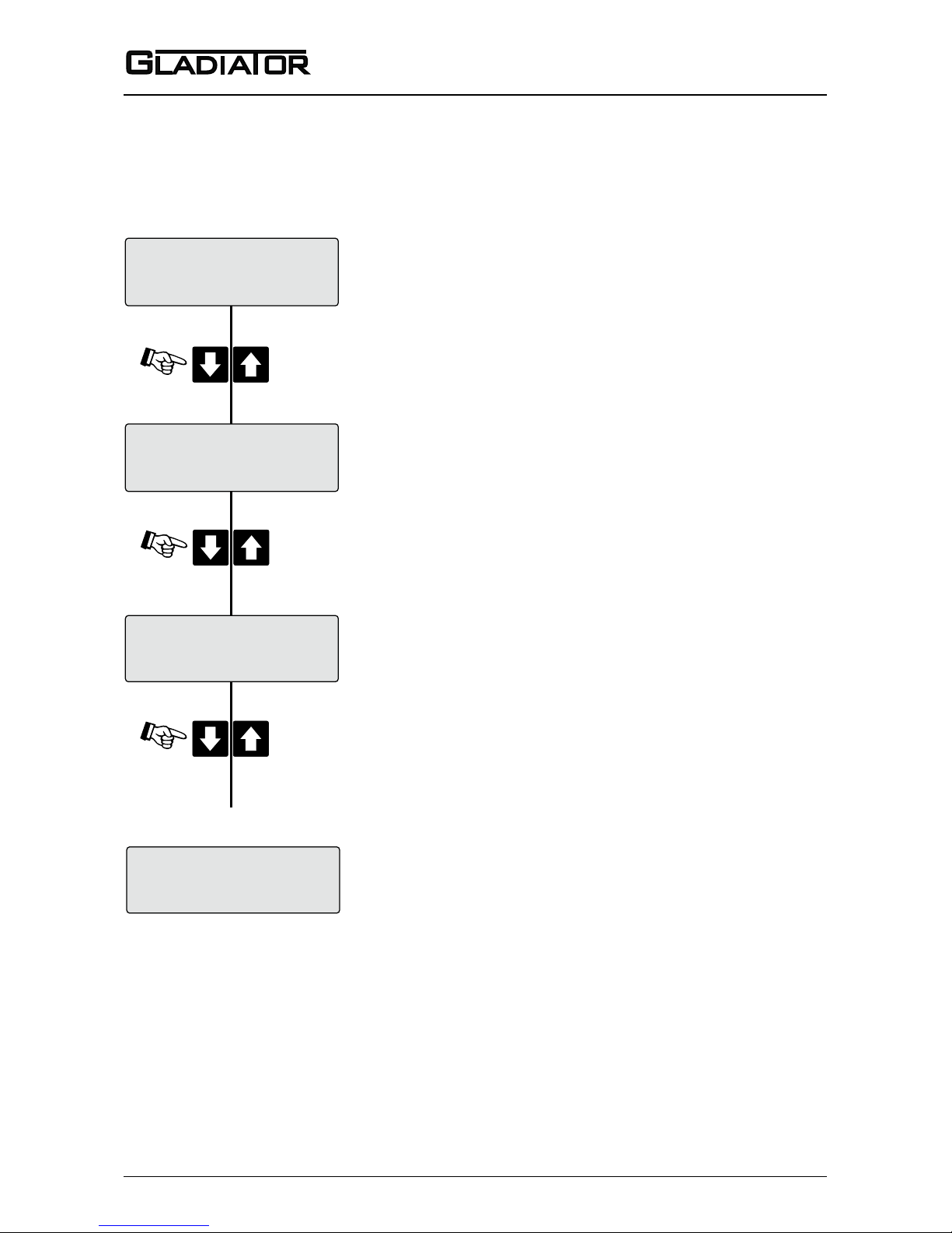
SwOff: 25%
0.0%
SwOn: 50%
0.0%
Press
Press
Max: 72.9%
0.0%
Percentage below which the Relay will be in
State 1*.
Press
Sensor Value
0.0%
Returns to
Percentage above which the Relay will be in
State 2*.
*Switch points are refered to as ‘On’ and ‘Off’ to
reflect the most simply understood performance in
FailSafe Low mode. Actual relay state may be different
according to setting of relay contact action.
Maximum captured Sensor Value % since last
history log reset, or last Cal Mounting operation.
FLOW CHART
DIAGNOSTIC DISPLAYS
(see page 14)
Page 32
31
Sultan 234 Series
Admittance Smart Switch Series
Manual
Rev 1.2, June 2008
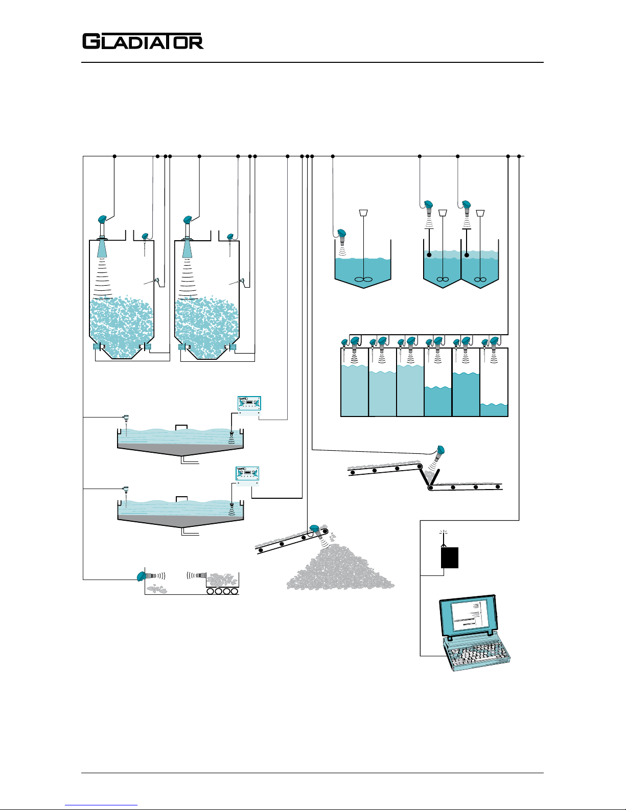
Laptop or PC Communications
or PLC / DCS with
MODBUS RTU Port
GosHawk Software for
inventory monitoring on PC
GSM Network
or
CDMA Network
Floatation Cells
Sultan Acoustic
Wave Transmitter
Slurries
Gladi ator
Admit tance
Switc h
Sultan Acoustic Wave Transmitter
Silo, bin levels, coal, plastic powder,
woodchip, sawdust, cement,
clinker, iron ore, lime etc.
Orca Sonar Interface
Thickener, CCD
GSM or CDMA Network
•
Typically up to 31 transmitters or switches per string.
•
Maximum 250 transmitters or switches.
•
Using GSM/CDMA network, transmitters and switches can be
monitored, calibrated remotely.
•
Alarm status, diagnostics can be monitored.
•
Support from factory engineering for customer application problems.
Sultan Acoustic Wave Transmitter
Stockpiles, Stackers,
Reclaimers
Sultan Acoustic
Wave Switch
Blocked Chute Detection
Sultan Smart Transducer
Farm Tanks, Grain Terminals
Orca Sonar Interface
Clarier
SULTAN 234
SULTAN 234
Gladi ator
Admit tance
Switch
Gladi ator
Vibra tion
Switch
Gladi ator
Admit tance
Switc h
Gladi ator
Admit tance
Switch
Microw ave
Low Leve l
Microw ave
Low Leve l
Sultan Master/Slave Positioning System
Gladi ator
Conduc tivi ty
Switch
Gladi ator
Conduc tivi ty
Switch
(Limited Modbus query rate for Switches only)
Sultan Acoustic
Wave Transmitter
MULTIDROP CONNECTIONS
Page 33
32
Admittance Smart Switch Series
Manual
Rev 1.2, June 2008
33
HawkLink GSM/CDMA communication
device allows any authorized computer
with a standard modem and
GosHawkII
software to dial in and calibrate, test
or check in on the performance of the
connected Hawk product. The HawkLink
device can be wired to the standard
communication terminals of the Hawk
products.
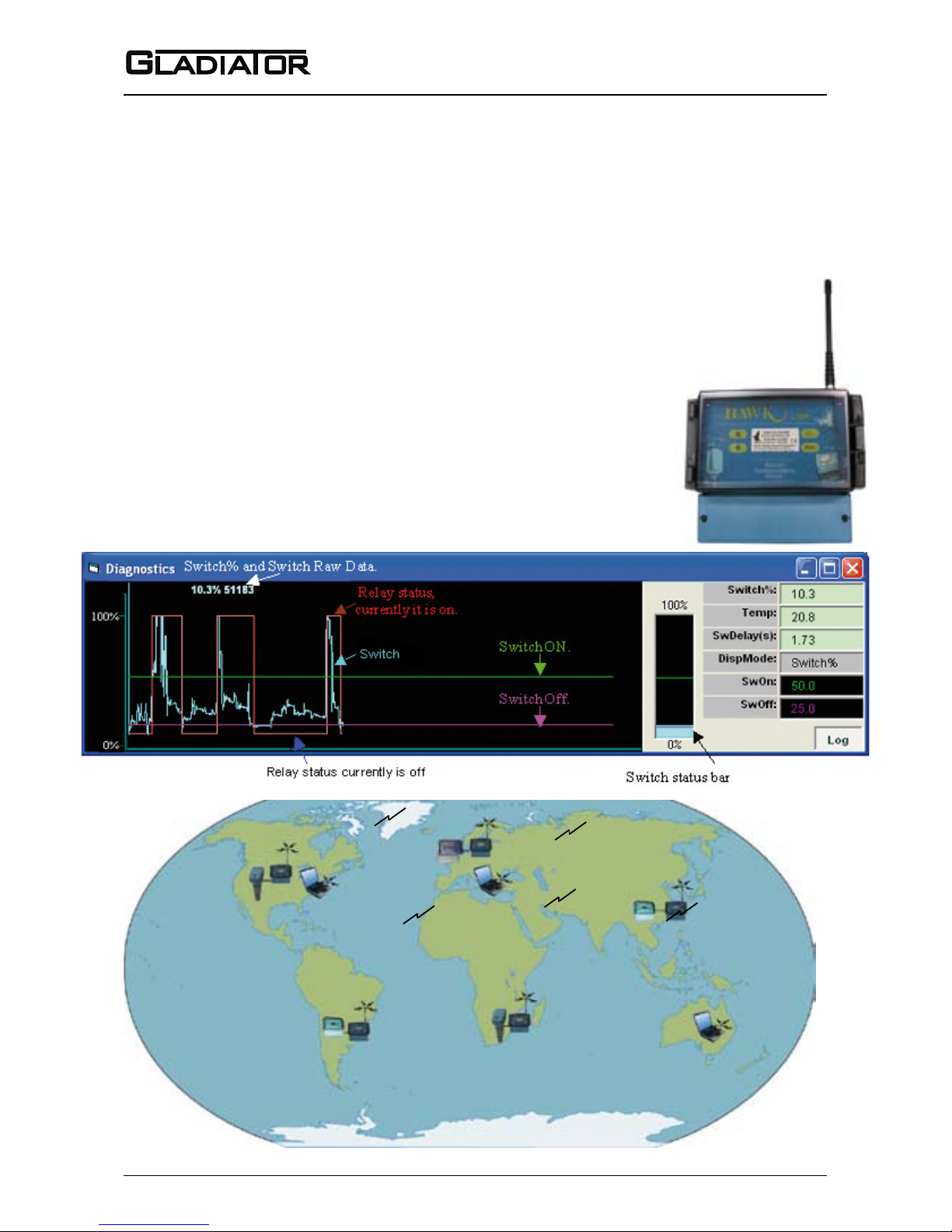
Remote connection worldwide!
ADVANCED REMOTE COMMUNICATION
GSM/CDMA
Remote technical support and complete
commissioning of equipment in applications is possible via our GSM/CDMA
module and allows monitoring and
adjustment of settings no matter what
corner of the world.
Page 34

33
Sultan 234 Series
Admittance Smart Switch Series
Manual
Rev 1.2, June 2008
TROUBLESHOOTING
REMOTE VERSION
Operation Setup Check
After nal adjustment it is advisable to
check the performance of the probe
relative to your entered settings.
Ensure there is no mounting inuence.
When calibrating the mounting of the
unit, there should be no product within
at least 500mm of the probe. After calibrating the unit the Sensor Value (%)
should read approximately 0.0% with
no product near or touching the probe.
Allow infeed to occur and note the Sensor Value (%) change (if there is any) as the level gets closer to the probe the
Sensor Value (%) number will increase
and continue to increase as the product
gets closer to, touches and covers the
probe.
The Gladiator is capable of switching
repeatably and reliably without product
contacting the probe for a wide variety
of materials. Some very low dielectric
materials may need to touch the probe
to be detected.
The Sensor Value (%) will reach its
maximum after the probe is covered
- but the Switch Point can be set at any
value less then the maximum. It is recommended to select the set point more
than 10% below the maximum value
seen with material touching the probe.
For instance the following readings may
occur during lling:
Sensor Value (%)
- Before lling 0.0%
- Filling starts 0.7%
- Filling continue 4.9%
- Filling continue 27.5%
- Material approaching probe 48.5%
- Material contacts probe 96.5%
- Material covers probe 285.7%
A. You may choose to leave the Switch
Point at the default 50%. The Gladiator
will switch reliably without contact of
the material to the probe.
B. You may choose to adjust the Switch
Point to 100% to switch when the prod
-
uct contacts the probe.
By default the Switch Off % is set at 1/2
of the Switch Point. You may wish to
adjust this to a higher or lower number.
This is adjustable in the Advanced
Menu by selecting Switch Mode - Manual. You can then manually select your
Switch On and Switch Off values.
In general, you should not choose the
Max Sensor % (Max) value nor the Min
Sensor % (Min) value as the Switch
Point.
If possible, always have the Switch On
% at a value of at least 10% less than
the Max Sensor % (Max) value and
Switch Off at least 10% more than the
Min Sensor % (Min).
If the % change on the display is too
small then the Display Span parameter
in the Advanced menu can expand the
display resolution (select a larger number - smaller raw range) and vice versa.
Changing the Display Span will change
Switch Point value.
Page 35
34
Admittance Smart Switch Series
Manual
Rev 1.2, June 2008
35
PART NUMBERING
SMART PROBE VERSION
AS2100 Gladiator Admittance Switch - Smart Probe
Power Supply
B 24 Vdc standard (7-30Vdc)
U Universal AC power supply (80-260Vac input) and 7-30Vdc
Output Options
S Switch only, 1 level relay, Modbus
Z Special Request
Housing
S Standard Powder Coated, Diecast with glass lid
C Corrosion Resistant, stainless steel housing
Guard Length (excludes 100mm ground length)
1 150 mm (5.9”)
Z Special Request
Temperature
1 Maximum 80ºC (176ºF)
2 Maximum 150ºC (302ºF) Temperature extension length 150 mm (5.9”), Teon
3 Maximum 250ºC (482ºF) Temperature extension length 250 mm (9.8”), Teon
4 Maximum 450ºC (842ºF) Temperature extension length 350 mm (13.7”), Ceramic
Probe Type
1 Standard rod (non-insulated)
2 Insulated rod
3 Cable (non-insulated)
Mounting
TN07 3/4” NPT Thread (not available with high temp ceramic version)
TB07 3/4” BSP Thread (not available with high temp ceramic version)
TN10 1” NPT Thread (not available with high temp ceramic version)
TB10 1” BSP Thread (not available with high temp ceramic version)
TN15 1.5” NPT Thread
TB15 1.5” BSP Thread
TZ Special Thread Request
FA2 2” Flange ANSI (Class 150)
FD2 2” Flange DIN 50 (PN 40)
FJ2 2” Flange JIS (10K)
FZ Special ange request
Approvals
A22 ATEX 22 (Pending)
X Standard CE Approved
(P)Probe (C)Cable Length
P30 - 300mm (11.8”)
P50 - 500mm (19.6”)
P100 - 1000mm (39.3”)
C100 - 1000mm (39.3”)
C200 - 2000mm (78.7”)
C300 -
3000mm (118.1”)
For longer consult factory
AS2100
B S S 1 1 1
TB15
X P30
Page 36
35
Sultan 234 Series
Admittance Smart Switch Series
Manual
Rev 1.2, June 2008
Remote Amplier
GSA Remote Gladiator System Amplier
Housing
S Standard polycarbonate electronics housing
Power Supply
B 24 Vdc standard (12-30Vdc)
C 48Vdc
U Universal AC power supply (80-260Vac input) and 7-30Vdc
Output Options
S Switch only, 1 level relay, 1 failsafe relay, Modbus
I HART Isolated, 1 level relay, 1 failsafe relay
D Probus DP, 1 level relay, 1 failsafe relay
P Devicenet, 1 level relay, 1 failsafe relay
Z Special Request
GSA S B S
Remote Probe
AS2200 Remote Gladiator Admittance Probe
Housing
S Standard Powder Coated, Diecast with glass lid
C Corrosion Resistant, stainless steel housing
Guard Length (excludes 100mm ground length)
1 150 mm (5.9”)
Z Special Request
Temperature
1 Maximum 80ºC (176ºF)
2 Maximum 150ºC (302ºF), temperature extension length 150 mm (5.9”), Teon
3 Maximum 250ºC (482ºF), temperature extension length 250 mm (9.8”), Teon
4 Maximum 450ºC (842ºF), temperature extension length 350 mm (13.7”), Ceramic
Probe Type
1 Standard rod (non-insulated)
2 Insulated rod
3 Cable (non-insulated)
Mounting
TN07 3/4” NPT Thread (not available with high temp ceramic version)
TB07 3/4” BSP Thread (not available with high temp ceramic version)
TN10 1” NPT Thread (not available with high temp ceramic version)
TB10 1” BSP Thread (not available with high temp ceramic version)
TN15 1.5” NPT Thread
TB15 1.5” BSP Thread
TZ Special Thread Request
FA2 2” Flange ANSI (Class 150)
FD2 2” Flange DIN 50 (PN 40)
FJ2 2” Flange JIS (10K)
FZ Special ange request
Approvals
A22 ATEX 22 (Pending)
X Standard CE Approved
(P)Probe (C)Cable Length
P30 - 300mm (11.8”)
P50 - 500mm (19.6”)
P100 - 1000mm (39.3”)
C100 - 1000mm (39.3”)
C200 - 2000mm (78.7”)
C300 - 3000mm (118.1”)
For longer consult factory
AS2200 S 1 1 1
TB15
X P30
PART NUMBERING
REMOTE VERSION
Page 37

36
Admittance Smart Switch Series
Manual
Rev 1.2, June 2008
37
SPECIFICATIONS
Operating Voltage
• 7 - 30Vdc (residual ripple no greater than
100mV)
• 80 - 260Vac 50/60Hz
Power Consumption
• <0.8W @ 24Vdc
• <5VA @ 240Vac
• <3VA @ 115Vac
Communications
• GosHawk, Modbus
• Remote version also with HART,
Probus DP and DeviceNet (options)
• Multidrop mode can address 1-250 units
over 4 wires
Relay Output: (1) SMART (2) Remote
• Form ‘C’ (SPDT) contacts, rated 5A at
240Vac resistive
• Remote failsafe test facility for one relay.
Measurement Range
• 0.2pF - 100nF
Resolution
• 0.01 pF
Electronic Accuracy
• 0.05 pF
Stability
• 0.01% / °C
Operating Temperature
• Remote electronics -40°C (-40°F) to 80°C (176°F)
• Smart Probe -40°C (-40°F) to 450°C 842°F)*
• Remote Probe -40°C (-40°F) to 450°C (842°F)*
Probe/Amplier Separation
• up to 500m (1640ft) using specied exten-
sion cable
Cable type between Amplier and Probe
• 4 conductor shielded twisted pair instrument
cable.
Conductor size dependent on cable length.
BELDEN 3084A, DEKORON or equivalent.
Max: BELDEN 3084A = 500m (1640 ft)
Max: DEKORON IED183AA002 = 350m
(1150 ft)
Maximum Operating Pressure
• 2 BAR
Display (Remote version only)
• 2 line x 12 character alphanumeric LCD
• Backlight standard
Memory - Remote
• Non-Volatile (No backup battery required)
• >10 years data retention
Enclosure Sealing
• Smart Probe IP67
• Remote Electronics IP65 (Nema 4x)
• Remote Probe IP67
Cable Entries
BSP process mounting
• 2 x M20 glands
NPT process mounting
• 2 x 3/4” NPTF threaded adaptors
Remote
3 x 20mm (0.8”), 1 x 16mm (0.6”) knock outs
Mounting
• 3/4” NPT or BSP Thread
• 1” NPT or BSP Thread
• 1.5” NPT or BSP Thread
• 50mm (2”) Flange (ANSI, DIN or JIS
patterns available)
Remote Test Input
Press to test
(used to check for malfunction of
unit from remote position, PLC, SCADA etc)
*correct temperature range probe must be specied when ordering
Patents Pending
Page 38

37
Sultan 234 Series
Admittance Smart Switch Series
Manual
Rev 1.2, June 2008
DIELECTRIC CONSTANTS TABLE
Dielectric
Material Constant
Glycerine 47.0
Glycer ol 43.0
Glycol 35.6
Heptane 1.9
Heptanoic Acid 2.5
Hexane 1.9
Hydrogen Bromide 3.8
Hydrogen Chloride 4.6
Hydrogen Cyanide 95.4
Hydrogen Fluoride 84.0
Hydrogen lodide 2.9
Hydrogen Peroxide 84.2
Hydrogen Sulfide 5.8
Hydrazine 52.9
lodine 118.0
Isobutyl Alcohol 18.7
Kerosene 1.8
Lead Oleate 3.2
Lonone 10.0
Menthol 3.95
Mesityl Oxide 15.4
Methanol 33.6
Methyl Alcohol 33.0
Methyl Ether 5.0
Methyl Ether Ketone 18.4
Mineral Oil 2.1
Nephthyl Ethyl Ether 3.2
Nitroethane 19.7
Nitromethane 39.4
Octane 1.96
Octyl Alcohol 3.4
Octylene 4.1
Oleic Acid 2.46
Oil, Oiive 3.1
Oil, Peanut 2.2
Oil, Transformer 2.2
For other materials contact the factory
Dielectric
Material Constant
Acetal 3.6
Acetic Acid 6.1
Acetone 17.7
Acetyl Acetone 23.1
Acetyl Bromide 16.5
Allyl Alcohol 21.0
Allyl Bromide 7.0
Allyl Choloride 8.2
Allyl lodide 6.1
Ammonia 15.5
Amyl Alcohol 11.2
Amyl Bromide 6.3
Amyl Choloride 6.6
Amyl Ether 3.1
Amyl lodide 6.9
Amyl Nitrate 9.1
Arsenic Tribromide 9.0
Arsenic Trichloride 12.4
Arsenic Triiodide 7.0
Asphalt 2.65
Benzene 2.3
Benzil 13.0
Benzoyl Chloride 22.1
Benzyl Alcohol 13.0
Benzyl Chloride 6.4
Boron Bromide 2.6
Bromine 3.1
Butane 1.4
Butyl Chloride 9.6
N Butyl lodide 6.1
Iso Butyl lodide 5.8
Cable Oil 2.2
Camphene 2.7
Carbon Dioxide 1.6
Carbon Disulphide 2.6
Carbon Tetrachloride 2.2
Dielectric
Material Constant
Castor Oil 2.6
Camphene 2.3
Cement 2.1
Chloracetic acid 12.3
Chlorine 2.0
Chloroform 5.5
Cr eosol 10.6
Cyclohexane 2.0
Deuterium 1.3
Deuterium Oxide 78.3
Dichloracetone 14.0
Dichlorobenzene 2.8
Dichloroethane 16.7
Diethyl Sulfide 7.2
Dimethyl Ethyl 11.7
Dimethyl Sulfide 6.3
Dimethyl Sulfate 55.0
Dowtherm 3.3
Ethanol 24.3
Ethyl Acetate 6.4
Ethyl Amyl Ether 4.0
Ethyl Benzene 2.5
Ethyl Benzoate 6.0
Ethyl Cyclobutane 1.9
Ethylene Chloride 10.5
Ethylene Cyanide 58.3
Ethylene Glycol 37.0
Ethylene Oxide 13.9
Ethyl lodide 7.4
Ethyl Nitrate 19.7
Ethyl Silicate 4.1
Fly Ash 2.6
Formic Acid 58.5
Freon 12 2.4
Freon 11 3.1
Freon 113 2.6
Dielectric
Material Constant
Palmitic Acid 2.3
Pentane 1.8
Phenol 9.9
Phenol Acetate 6.9
Phosgene 4.7
Phosphorus 4.1
Polyethylene chips 1.3
Polyethylene powder 1.4
Propyl Acetate 6.3
Propyl Alcohol 21.8
Propyl Benezene 2.4
Pyridine 12.5
Reburned Lime 2.2
Sand (Dry) 4.8
Sodium Chloride 6.1
Sodium Oleate 2.7
Succinic Acid 2.4
Sodium Chloride 6.1
Sulphur 3.4
Sulphur Dioxide 17.6
Sulfuryl Chloride 10.0
Sulphur Trioxide 3.6
Teflon Powder 1.3
Teterabromiethane 7.1
Thionyl Bromide 9.1
Thionyl Chloride 9.3
Titanium Tetrachloride
2.8
Toluene 2.4
Trichloroxoluene 6.9
Trimetylbenzene 2.2
Trimethyl Borate 8.2
Urethane 3.2
Valeric Acid 2.6
Vinyl Ether 3.9
Water 80.0
Xylene 2.4
Page 39

38
Admittance Smart Switch Series
Manual
Rev 1.2, June 2008
DECLARATION OF CONFORMITY
Manufacturer’s Name: HAWK MEASUREMENT SYSTEMS PTY LTD
Manufacturer’s Address: 15–17 Maurice Court
Nunawading, Vic.
Australia 3131
declares that the product Gladiator Variable Admittance Level Switch series
Models AS2000, AS2100, AS2200, AS2210, and GARP.
conform to the following product specifications:
Low Voltage Directive: 73/23/EEC
Amendment Directive: 93/68/EEC
EMC Directive: 89/336/EEC
ATEX Directive: 94/9/EEC
Standards in whole or in part to which conformity is declared:
Normative Documents: EN 61326: 1997 +Amendment 1: 1998 + Amendment 2:2001
EN 61010-1:2001
BS EN 50014:1998
EN 50281-1-1:1998
Standards: IEC 1000-3-2: 1995
IEC 1000-3-3: 1994
IEC 1000-4-2: 1995
IEC 1000-4-3: 1995
IEC 1000-4-4: 1995
IEC 1000-4-5: 1995
IEC 1000-4-6: 1996
IEC 1000-4-11: 1994
Supplemental Information:
The product herewith complies with the requirements of Low Voltage Directive 73/23/EEC, Amendment
Directive 93/68/EEC, and EMC Directive 89/336/EEC, when the probe is installed to monitor material in a
closed metal vessel, and carries the CE-marking accordingly. The Remote amplifier is safe for operation
in Category 3 hazardous locations (Zone 2/22) and the Integral and Remote Probes have been designed
to operate in Cat 1 and 2 (Zone 20/21) dust locations. The ATEX marking code is
®
II 3 GD IP67 T65ºC.
Signature:
Name: Colin Prohasky
Position: Engineering Manager
Date: 10 October 2007
Place: Melbourne, Australia.
HAWK MEASUREMENT SYSTEMS
PTY. LTD. A.C.N. 006 782 449
15-17 MAURICE COURT
NUNAWADING VIC. 3131
P.O. BOX 286 NUNAWADING
VIC. 3131 AUSTRALIA
EMAIL: [email protected]
PH: +61-3 9873 4750
FAX: +61-3 9873 4538 (Sales/Engineering)
FAX: +61-3 9873 4384 (Accounts/Production)
Page 40

Hawk Measurement Systems (Head Ofce)
15-17 Maurice Court
Nunawading VIC 3131
Australia
Phone: +61 3 9873 4750
Fax: +61 3 9873 4538
[email protected]
Hawk Measurement
7 River Street
Middleton, MA 01949
USA
Phone: +1 888 HAWKLEVEL (1-888-429-5538)
Phone: +1 978 304 3000
Fax: +1 978 304 1462
[email protected]
For more information and global
representatives:
www.hawkmeasure.com
Represented by:
Contacts
Part no. DOC-ADMITTANCE-MAN
Rev 1.2, June 2008
 Loading...